EP2873969B1 - Système de mesure d'hématocrite et procédé de mesure l'utilisant - Google Patents
Système de mesure d'hématocrite et procédé de mesure l'utilisant Download PDFInfo
- Publication number
- EP2873969B1 EP2873969B1 EP14003223.6A EP14003223A EP2873969B1 EP 2873969 B1 EP2873969 B1 EP 2873969B1 EP 14003223 A EP14003223 A EP 14003223A EP 2873969 B1 EP2873969 B1 EP 2873969B1
- Authority
- EP
- European Patent Office
- Prior art keywords
- hct
- capacitance
- signal
- test strip
- measurement
- Prior art date
- Legal status (The legal status is an assumption and is not a legal conclusion. Google has not performed a legal analysis and makes no representation as to the accuracy of the status listed.)
- Active
Links
Images






Classifications
-
- G—PHYSICS
- G01—MEASURING; TESTING
- G01N—INVESTIGATING OR ANALYSING MATERIALS BY DETERMINING THEIR CHEMICAL OR PHYSICAL PROPERTIES
- G01N27/00—Investigating or analysing materials by the use of electric, electrochemical, or magnetic means
- G01N27/26—Investigating or analysing materials by the use of electric, electrochemical, or magnetic means by investigating electrochemical variables; by using electrolysis or electrophoresis
- G01N27/28—Electrolytic cell components
- G01N27/30—Electrodes, e.g. test electrodes; Half-cells
- G01N27/327—Biochemical electrodes, e.g. electrical or mechanical details for in vitro measurements
-
- G—PHYSICS
- G01—MEASURING; TESTING
- G01N—INVESTIGATING OR ANALYSING MATERIALS BY DETERMINING THEIR CHEMICAL OR PHYSICAL PROPERTIES
- G01N27/00—Investigating or analysing materials by the use of electric, electrochemical, or magnetic means
- G01N27/26—Investigating or analysing materials by the use of electric, electrochemical, or magnetic means by investigating electrochemical variables; by using electrolysis or electrophoresis
- G01N27/28—Electrolytic cell components
- G01N27/30—Electrodes, e.g. test electrodes; Half-cells
- G01N27/327—Biochemical electrodes, e.g. electrical or mechanical details for in vitro measurements
- G01N27/3271—Amperometric enzyme electrodes for analytes in body fluids, e.g. glucose in blood
- G01N27/3274—Corrective measures, e.g. error detection, compensation for temperature or hematocrit, calibration
Definitions
- the present invention relates to a hematocrit measurement system and a measurement method thereof, and more particularly to a hematocrit measurement system having a capacitive reactance adjustor and a method of improving capacitive reactance characteristics of the blood hematocrit using the capacitive reactance adjustor so as to enhance measurement accuracy.
- HCT hematocrit
- U.S. Patent No. 5,628,890 discloses a test strip for an electrochemical system.
- a filter layer is disposed on the test strip to separate the red blood cells from the blood sample to be tested.
- the method disclosed in this patent has drawbacks such as difficulty to process the test strip, high cost, long measurement time taken, and large amount of measurement blood needed.
- U.S. Patent No. 7,407,811 discloses a method for detecting HCT and correcting the concentration of the blood to be tested.
- AC signals with frequencies in a range of 1 Hz-20 KHz are provided to test the blood sample.
- the phase angle and admittance magnitude of the blood can be measured and HCT values in the blood can be calculated therefrom.
- the technical solutions disclosed in this patent need repeatedly providing two to five signals with different frequencies to the tested blood. It would practical disadvantageous that the blood HCT is measured by signals with different frequencies, resulting in long overall reaction time, operational difficulties, and increased power consumption.
- U.S. Patent No. 8,480,869 discloses an HCT measurement method using a redox reaction in which ferricyanide or ferrocyanide is disposed on electrochemical test strip electrodes. After ferricyanide or ferrocyanide reacted with red blood cells, the HCT value can thereby be measured.
- the redox agents disclosed in U.S. Patent No. 8,480,869 may interfere with other enzymes on the electrochemical test strip, resulting in distortion of the measurement results.
- both U.S. patent Nos. 7,407,811 and 8,480,869 disclose methods to measure HCT values of the blood, other components existed in the blood can also pose a threat to the accuracy of HCT measurement.
- US 2013/084589 A1 discloses a hand-held test meter for use with an analytical test strip in the determination of an analyte in a bodily fluid sample includes a housing; a microcontroller block disposed in the housing; and a phase-shift-based hematocrit measurement block.
- the phase-shift-based hematocrit measurement block includes a signal generation sub-block, a low pass filter sub-block, an analytical test strip sample cell interface sub-block, a transimpedance amplifier sub-block, and a phase detector sub-block.
- phase-shift-based hematocrit measurement block and microcontroller block are configured to measure the phase shift of a bodily fluid sample in a sample cell of an analytical test strip inserted in the hand-held test meter and the microcontroller block is configured to compute the hematocrit of the bodily fluid sample based on the measured phase shift.
- US 2008/211521 A1 discloses a moisture content sensor comprising a signal source arranged to provide a signal, a probe arranged to inject the signal into a medium in which the moisture content is to be measured, a complex impedance placed between the probe and the signal source and sensing electronics arranged to monitor the signal at a point between the signal source and the complex impedance and generate a primary measurement therefrom which is indicative of the moisture content of the medium.
- One aspect of the present invention provides an HCT measurement system, comprising a measuring apparatus and a test strip insertable in the measurement apparatus, wherein blood HCT capacitance characteristics and measurement accuracy can thus be effectively improved using a blood measuring instrument with capacitive reactance characteristic adjustor.
- the electrochemical test strip includes at least one pair of electrodes or a plurality of electrodes, the electrodes being insulated from each other and forming an electrical circuit with the measurement apparatus upon insertion of the test strip in the measurement apparatus and upon application of the blood sample onto the electrodes.
- the measurement apparatus comprises: a power generator adapted to provide a wave function signal to the electrochemical test strip; a connector for external connection of the test strip and for transmitting an initial signal generated from a blood sample to the measurement apparatus; a calculation unit for acquiring a measurement signal, the calculation unit including a divider resistor and a signal processor, and the calculation unit further including a capacitive reactance adjustor, wherein said capacitive reactance adjustor is disposed between the test strip and the divider resistor of the calculation unit, the capacitive reactance adjustor comprising a circuit consisting of a loading resistor and at least one adjusting capacitor; an A/D converter for transforming the measurement signal into a digital reacted signal; and a digital signal processor for processing the digital signal and showing measured results on a display, wherein during measurement, the wave function signal provided by power generator is transmitted to electrochemical test strip, where the blood sample applied on the test strip reacts with the wave function signal to generate a corresponding response signal which is further transmitted through the connector to the calculation unit, which response signal
- the calculation unit measures the signal to calculate the HCT value of the blood sample such that distortion measurement signal curves due to saturated or cut off signal waveform voltage is prevented.
- the calculation unit measures voltage division signal to calculate the HCT value of the blood sample such that distortion measurement signal curves due to saturated or cut off signal waveform voltage can be prevented.
- a method for measuring hematocrit (HCT) using the HCT measurement system comprising: providing an electrochemical test strip; placing the electrochemical test strip into the HCT measurement system as claimed in claim 1; providing a wave function signal which is transmitted from the power generator through the connector and the capacitive reactance adjustor to the electrochemical test strip; acquiring a measuring signal through the calculation unit; digitizing the measuring signal by an analog-digital converter and transmitting the digital signal to the digital signal processor; analyzing the measuring signal through the digital signal processor; and showing a measured HCT value received from the digital signal processor on a display, or using the HCT value to calculate biochemical concentration values, which biochemical concentration values are preferably selected from glucose, cholesterol, uric acid, lactic acid, and hemoglobin concentration values.
- Embodiments of the present invention provide a method for measuring blood HCT using a biochemical system.
- the biochemical system comprises a measurement apparatus and an electrochemical test strip, wherein the electrochemical test strip includes at least one pair of electrodes.
- the users When operating measurement, the users must insert the electrochemical test strip into the measurement apparatus. Their skin is then pricked using a blood collection needle to ooze trace blood, which is directly dripped onto the electrochemical test strip.
- HCT concentration can be measured by measuring the resistance and capacitance of the blood. That is because the red blood cells in the blood include capacitive and resistance characteristics in structure such that there is a direct relationship between use of the capacitive and reactance characteristics and the HCT concentration.
- an electrochemical test strip 100 includes an insulating substrate 102, an electrode system 104, an insulating layer 106, a lower separation plate 108, a hydrophilic separation plate 110 and an upper separation plate 112.
- the insulating substrate 102 is an electrically insulating substrate, and its material may include, but are not limited to: polyvinyl chloride (PVC), glass fiber, polyester, bakelite, polyethylene terephthalate (PET), poly carbonate esters (PC), polypropylene (PP), polyethylene (PE), polystyrene (PS), ceramic or any combination thereof.
- PVC polyvinyl chloride
- PET polyethylene terephthalate
- PC poly carbonate esters
- PP polypropylene
- PE polyethylene
- PS polystyrene
- Materials of the electrode system 104 may include any conductive material, such as carbon plastic, silver plastic, copper, rubber, gold and silver mixed glue, carbon silver mixed glue, or any combination thereof.
- the electrode system is composed of a carbon powder conductive layer.
- the electrode system is composed of a metal layer.
- the electrode system is composed of a silver-based conductive layer and a carbon powder conductive layer located thereon, wherein impedance of the carbon powder conductive layer is typically much greater than those of the silver-based conductive layer or other metal layer.
- the electrode system in response to the actual needs in measurement, can be a set of electrode consisting of a plurality of electrodes insulated from each other.
- the electrode system comprises a concentration electrode set and an HCT electrode set.
- the concentration electrode set comprises a working electrode and a reference electrode insulating from each other.
- the HCT electrode set comprises a first HCT electrode and a second HCT electrode.
- the working electrode, the reference electrode, the first HCT electrode and the second electrode are electrically connected to a measurement apparatus and a blood sample respectively.
- the present invention does not intend to limit the configuration of the electrodes, only if an electrical circuit can be formed between the electrode set and the measurement apparatus. Generally, it would be sufficient to exploit the present invention as long as each electrode of the aforementioned electrode configuration is insulated from each other before connecting the blood sample.
- Embodiments of the present invention does not intend to limit the arrangement between the electrodes and does not intend to limit the number of electrodes neither, other electrodes may be added depending on the practical application.
- the insulating layer 106 covers part of the electrode system 104 so that a reaction zone for receiving a blood sample is formed at one end of the electrode system 104 not covered while the other end forms a connection area in contact with the measurement apparatus, wherein the reaction zone includes an inlet for injecting the blood sample.
- Materials of the insulating layer 106 can include, but are not limited to a PVC insulating tape, a PET insulating tape, a thermal drying insulating paint or an ultraviolet drying insulating paint.
- the electrochemical test strip 100 may include at least one reaction layer disposed in the reaction zone.
- the reaction layer contains at least one oxidoreductase to produce a chemical reaction with the blood sample, wherein the type of oxidoreductase is determined depending on the nature of the blood sample. Further, the reaction layer covers at least part of the reaction zone of the electrode system.
- the lower separation plate 108 is disposed over the insulating layer 106, and the lower separation plate 108 includes an opening 109 exposing a portion of the electrode system. Generally, it would be sufficient to implement as long as the opening 109 exposed part of the electrode system. The present invention does not intend to limit the shape of the opening 109. Further, the connecting region of the insulating substrate 102 is exposed by the lower separation plate 108 such that one end of the connection area of the electrode system electrically connects the measurement apparatus.
- Material of the lower separation plate 108 can include, but are not limited to a PVC insulating tape, a PET insulation tape, a thermal drying insulating paint or an UV curable insulating paint.
- the lower separation plate with the trimmed opening can be placed on the insulating substrate and the electrode system.
- the lower spacer can be formed on part of the insulating substrate and the electrode system by directly printing and selectively avoid the opening 109 and the position of the connection region of the insulating substrate.
- Materials of the upper separation plate 112 can include, but are not limited to transparent or translucent material so as to easily observe whether the reaction zone is filled with the blood sample and to avoid testing under blood sample unfilled, resulting in erroneous measurements.
- the lower surface of the upper separation plate 112 near the reaction zone can be coated with a hydrophilic spacer 110 to enhance capillary action on the internal walls of the reaction zone and more rapidly and efficiently introduce the blood sample into the reaction zone.
- the upper separation plate 112 further comprises a vent hole corresponding to the openings (not shown) to enhance capillary action, exhausting gas in the reaction zone.
- the vent hole is disposed near the end of the inner closed opening.
- Embodiments of the present invention are not limited to the shape of the vent hole, for example, circular, oval, rectangular, diamond, etc.
- the electrochemical test strip 100 can be provided with an identification unit 114, which is formed on the side of upper surface of the electrode system 104 which is in contact with the measurement apparatus.
- the identification unit 114 includes a plurality of electrical components.
- the electrical component can be a variety of electrically conductive elements such as electrical elements having electrical characteristics of passive components.
- the electrical element can be a resistor which is the same as the material of the electrode system 104.
- the electrical element can be formed by screen printing, imprinting, thermal transfer printing, spin coating, ink-jet printing, laser ablation, deposition, electroplating, or screen-printing.
- the electrical device comprised in the identification unit 114 may include resistors, capacitors, inductors, and/or combinations thereof.
- the measurement device can identify the location and quantity of each electrical component on the electrochemical test strip 100 meter, thereby identifying the kind of the electrochemical test strip 100 and further adopting corresponding correction parameters or measurement modes.
- the number and location of a plurality of electrical components determine an identification code of the electrochemical test strip 100 so that the measurement apparatus can accordingly identify electrochemical test strip 100.
- the present invention does not intend to limit the number, shape and configuration of the electrical elements comprised in the identification unit 114.
- the present invention does not intend to limit the location and operating mode of identification unit 114.
- the only implement criteria for the identification unit 114 is that the identification code can be read by the measurement apparatus.
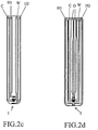
- Figs. 2a-2d schematically show layouts of the electrode system according to some embodiments of the present invention.
- an electrode system comprised a plurality sets of electrodes is disposed on a single electrochemical test strip.
- the electrode system includes but is not limited to a concentration electrode set and an HCT electrode set.
- the concentration-electrode set includes at least one working electrode W and a reference electrode C.
- HCT measurement does not contain redox reaction. Since a signal waveform is provided by the measurement apparatus in the blood, the HCT response signal can be measured therefrom.
- the HCT electrode set for measuring HCT is composed of a first HCT electrode H1 and a second HCT electrode H2.
- arrangement of each electrode set is not particularly limited.
- the blood sample infuses into entrance I of the reaction zone, it comes into contact with the HCT electrode set and the concentration electrode set of the electrode system sequentially.
- the entrance sequence of the blood samples contacting electrodes of the reaction zone is not limited, and the electrode sets can be adjusted according to actual required measurement position, if only one electric loop can be formed between the electrode set and the blood sample, thus sufficient implementing measurement embodiments of the invention.
- configuration of the electrode set of the electrochemical test strip is shown in Fig. 2a .
- Working electrode W and reference electrode C of the concentration electrode set are set up closer to the entrance I of the blood sample than the HCT electrode set.
- alternative configuration of the electrode set of the electrochemical test strip is shown in Fig. 2b .
- the first HCT electrode H1 and the second HCT electrode H2 of the HCT electrode set are set up closer to the entrance I of the blood sample than the concentration electrode set.
- alternative configuration of the electrode set of the electrochemical test strip is shown in Fig. 2c .
- Working electrode W and reference electrode C of the concentration electrode set are set up between the first HCT electrode H1 and the second HCT electrode H2 of the HCT electrode set.
- configuration of the electrode set of the electrochemical test strip of the present invention can also be shown in Fig. 2d .
- the present invention does not intent to limit layouts and measuring the relationship between each of the electrode sets.
- the electrical connection relationship can be adjusted according to actual measurement needs.
- a single measurement implementation can be individually performed between the electrode sets. More than one measurement implementations can also be performed on the same electrode set. For example, HCT and concentration measurements can be implemented on the same electrode set.
- Another embodiment of the electrode system may include a shape electrode, which is electrically insulated from each measurement electrode. The shape electrode is configured to electrically connect with the measurement apparatus. When the electrochemical test strip is inserted into the measurement apparatus, an electrical loop is formed between the shape electrode and the measurement apparatus, thereby starting the measurement operation.
- the HCT value of the blood sample can be acquired through the HCT measurement method of the present invention, thereby using the HCT value to calculate the biochemical concentration values, which are not limited to glucose, cholesterol, uric acid, lactic acid, and hemoglobin.
- a waveform signal is applied to the reactive layer by the measurement apparatus. After the waveform signal is reacted with the blood sample, an electrical signal will be released, generating a corresponding response signal. By measuring the response signal, the HCT condition of the user can be revealed at the measurement moment.
- the waveform signal is defined as signals that are stabilized over time and are undulated with circulated current or voltage.
- the signals can be 100% of AC signals, or the AC and DC superimposed signals, preferably DC signal waveforms.
- the aforementioned DC waveform signal means when the measurement apparatus provides a signal to the reaction zone of the electrochemical strip, a single signal waveform sufficiently presents characteristics of the waveform, and the waveform characteristic signal does not contain a negative circulated signal.
- the DC waveform signal can be, but is not limited to a pulse wave, a square wave, a triangle wave or a saw-tooth wave.
- the preferable waveform signal is a square wave signal with frequency approximately in a range of 1 KHz-22 KHz. Voltage is in a range of 50 mV-5 V, preferably in a range of 300 mV-800 mV.
- Fig. 3 is a block diagram schematically illustrating a system of the measurement apparatus according to an embodiment of the present invention.
- the system of the present invention includes an electrochemical test strip320 and a measurement apparatus 310.
- the electrochemical test strip 320 comprises a concentration electrode set with a reference electrode C and a working electrode W for concentration measurement, and an HCT electrode set with a first HCT electrode H1 and a second HCT electrode H2 for HCT measurement.
- the measurement apparatus 310 includes a connector 311 for external connection, a calculator 312 for transforming a concentration and/or HCT value, an analog to digital converter 313, a processor 314 and a display 315.
- the blood sample After the blood sample flows into the reaction zone of the electrochemical test strip, the blood sample distributes over the concentration electrode set and the HCT electrode set.
- a waveform signal is applied by the power unit 316 to the HCT electrode set, the red blood cells in the blood reacts with an electrical signal to generate a corresponding response signal which is transmitted through the connector 311 to the calculation unit 310 of the measurement apparatus 312.
- the reaction signal is transformed and transmitted to the analog to digital converter (ADC), to get a digital response signal.
- ADC analog to digital converter
- the digital response signal is further processed by a processor 314, and/or the measurement results are presented on a display 315.
- Fig. 4 is an equivalent circuitry of a calculation unit 312a according to an embodiment of the present invention. Unlike traditional circuit direct using signal gaining measurement, the calculation unit 312a of the present embodiment adopts voltage division principles to get the blood HCT value. Technical effects such as prevention of measured signal curve distortion caused by signal cut off and/or saturation generated by signal voltage waveform can thus be achieved.
- the calculation unit 312a is comprised with a divider resistor 410 and signal processor 412. When a waveform signal is provided by the power supply unit 316 through the connector to the blood sample 322, the waveform signal will pass through the divider resistor 410, and the divider resistor 410 and the blood sample 322 are in series relationship.
- the measurement signal is then processed by a signal processor 412.
- the signal processor 412 can comprise but are not limited to an operational amplifier, an adder, a single integrator or a circuit composed thereof. More preferably, the signal processor is a subtractor.
- a lipid bilayer of the red blood cell constitutes an insulating layer.
- the insulating layer can divide the inner fluid and the outer fluid of the cells, thereby forming a capacitor-like structure.
- the red blood cells thus have physical characteristics similar to a capacitor.
- the amount of blood samples needed for the measurement system is approximately 15 ⁇ L-0.1 ⁇ L even lower.
- empirical experiment shows that 0.5 ⁇ L blood sample contains capacitance of 150 pF-1.5 nF.
- other components in blood can significantly interfere with the measuring signals, resulting in variation on the measurement results.
- the red blood cell membrane comprises Na+/K+-ATPase.
- sodium or potassium ions with electrical signals can be released from the Na+/K+-ATPase due to the potential difference between inside and outside the cell, so as to achieve a potential balance inside and outside the cell.
- a signal waveform is provided by the measurement apparatus. Potential in the blood changes as alternately applying the positive and zero potential. Repetitive potential difference between inside and outside the cell causes continuous import and export of sodium or potassium ions from the Na+/K+-ATPase to achieve a potential balance inside and outside the cell.
- the potential difference of the signal is the main course of the noise interference during HCT measurement, further affecting measurement accuracy.
- Fig. 5 is an equivalent circuitry of another computing unit 312b according to another embodiment of the present invention.
- a blood capacitance characteristic adjustment device 420 is particularly added in the junction of the electrochemical test strip and the measurement apparatus according to an embodiment of the invention.
- the capacitance characteristic adjustment device 420 is used to present an electrical connection relationship, thereby improving the capacitance accuracy measured by the measurement apparatus.
- the capacitance characteristic adjustment device 420 can amplify the HCT blood concentration value, the amount of blood sample required for the measurement is apparently reduced.
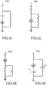
- Figs. 6a-6p show equivalent circuit diagrams of capacitance characteristic adjustment device according to embodiments of the present invention.
- the capacitance characteristic adjustment device may include, but is not limited to a load resistor and an adjustment capacitance.
- a junction "a" is created at the electrical connection between a voltage divider resistor and a signal processor.
- the adjusted capacitance component is composed of a single capacitor or a plurality of capacitive elements.
- the loading resistors of Figs. 6a , 6g and 6l can be substituted by the impedance of the electrochemical test strip.
- variation of electrode impedance values for each production batch may exist due to inevitable differences among each batch of material during the manufacturing process of the electrochemical test strip.
- the loading resistance of the capacitance characteristic adjustment device and the blood sample of the present invention are presented an electrical connection relationship.
- the impedance of the electrode can thus directly affect the electrical signals detected by the measurement apparatus.
- the impedance difference of each batch electrode may result in the difference variation of the electrochemical test strip batch by batch.
- Identification unit of the electrochemical test strip can thus be used to record the corrected impedance difference of the electrode of each batch.
- the measurement apparatus read the corrected impedance difference of the electrode of each batch through the identification unit.
- the measurement results are corrected by the correction value to avoid measurement errors created by batch-to-batch variation of the electrode impedance difference.
- the object of arranging the blood sample in parallel with the adjusted capacitor is to increase stored energy of the capacitance characteristics in the overall circuit, to increase the capacitance value of the overall circuit, and to improve sensitivity to the HCT characteristic signal. Further, by arranging the adjustment capacitor in parallel can stabilize voltage and filter the Na+/K+-ATPase and measurement noises caused by other components in the blood. Measure accuracy can also be improved such that calculation circuit can precisely calculate the capacitance characteristics of blood. In addition, reaction signal can be amplified by arranging the adjustment capacitance in parallel, thereby reducing the amount of blood samples needed to achieve the purpose of minimized detection.
- Fig. 7 schematically shows comparison results between the measured adjusted capacitor in parallel arrangement and the measurement apparatus without characteristic capacitance adjustor, illustrating the output signal-time relationship with respect to 10%, 30% and 50% of HCT concentration respectively.
- reaction begins occurring in the blood sample. Signals gradually rise to a steady state within at least 0.8 seconds.
- the adjustment capacitor is in parallel with the blood sample of the present invention.
- an electrochemical test strip is inserted into the measurement apparatus and starts measuring process, energy storage has been proceeding with the adjustment capacitor.
- the adjustment capacitor starts to release energy until the blood sample begins to release the response signal which is superimposed on the energy of released by the capacitor.
- the rise time of the response signal by the blood sample can thus be reduced within 0.4 seconds to a steady state, thereby with the effect of reducing the measurement time.
- the capacitors in series are equivalent to expanding the distance of capacitor electrode, thus reducing the overall capacitance.
- electrical signal detected by the measurement apparatus is also reduced.
- Detected noises caused by the Na+/K+-ATPase and other components in the blood may also be reduced such that the HCT concentration may be easily analyzed by a calculation unit, thereby effectively reducing influence by other components in the blood.
- the capacitor When the capacitor is both in series and in parallel with the blood sample, the blood sample is in series with Cci so as to reduce noise caused by the Na+/K+-ATPase and other components in the blood.
- the capacitance value of overall circuit is then increase by C C2 , to facilitate capture of the signal by the calculation unit.
- the adjusted capacitance value of capacitance characteristics adjustor there is no limitation to the adjusted capacitance value of capacitance characteristics adjustor.
- the capacitance value is limited to not affecting the capacitance properties of the blood sample.
- the capacitance value is preferable in a range of 1pF-150 ⁇ F, more preferable in a range of 50pF-20 ⁇ F.
- the response signal curve of the HCT with each measurement apparatuses can be acquired.
- the response curve can be converted to a current signal by means of a backend operation circuit.
- the HCT measurement signal containing interfering signals may present in the results in each measurement apparatus due to reaction caused by other components in the blood.
- Fig. 8 shows the comparing results of the coefficient of variation (CV) of the output signals by each measurement apparatus.
- CV coefficient of variation
- a mean error of comparative example 1 in which biological complex impedance measurement circuit is conjunction with a carbon electrode electrochemical test strip is 2.6%.
- the biological complex impedance measurement circuit is in conjunction with a metal electrode electrochemical test strip. Due to excellent conductivity of the metal electrode, influence on impedance of the electrode can thus be prevented.
- the coefficient of variation of the metal electrode is smaller than that of the carbon electrode. For example, the coefficient of variation of the metal electrode is 0.6%.
- the average measuring error is only 0.12% in conjunction with a carbon electrode electrochemical test strip, and can be maintained at 0.1% level for 10% to 60% concentration of measurement, the error is even close to 0.
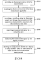
- Fig. 9 is a flow chart illustrating a method for HCT measurement using the HCT measurement system of the present invention.
- an electrochemical test strip for measurement is provided (step S810).
- the electrochemical test strip may include, but is not limited to four electrodes insulated from each other: a working electrode, a reference electrode, a first electrode HCT measurement electrode and a second HCT measurement electrode, wherein the first and second HCT measurement electrodes are electrically connected to the measurement apparatus and the capacitance characteristic adjustor.
- the adjusted capacitance of the capacitor characteristic adjustor and the blood sample are in series and/or in parallel relationship.
- the electrochemical test strip is inserted into a measurement apparatus (step S820).
- the measurement apparatus can be started by the insert action or be started manually.
- a waveform signal is provided by the power supply unit through the connector and the capacitance characteristics adjustor to the electrochemical test strip (step S830).
- a measurement signal is acquired by a computing unit (step S840).
- the signal of divided voltage can be measured by the measurement apparatus, and the signal processor of computing unit retrieves the signal on impedance of the voltage divider.
- the measurement signal is analyzed by the signal processor (step S850).
- the signal is digitized by an analog-digital converter and transmitted to the processor.
- the measurement results by the processor are shown on a display or the HCT value can be used for calculation of other biochemical concentration measurement (step S860).
- the digitized signal of the measurement results received by the processor can be directly displayed on a monitor, or other biochemical concentration can be calculated by means of the HCT value.
Landscapes
- Health & Medical Sciences (AREA)
- Chemical & Material Sciences (AREA)
- Life Sciences & Earth Sciences (AREA)
- Hematology (AREA)
- Analytical Chemistry (AREA)
- Chemical Kinetics & Catalysis (AREA)
- Electrochemistry (AREA)
- Physics & Mathematics (AREA)
- Molecular Biology (AREA)
- Biochemistry (AREA)
- General Health & Medical Sciences (AREA)
- General Physics & Mathematics (AREA)
- Immunology (AREA)
- Pathology (AREA)
- Investigating Or Analyzing Materials By The Use Of Electric Means (AREA)
- Investigating Or Analysing Biological Materials (AREA)
Claims (13)
- Système de mesure d'hématocrite (HCT), comprenant un appareil de mesure (310) et une bande d'essai électrochimique (320) insérable dans l'appareil de mesure (310),
dans lequel la bande d'essai électrochimique (320) inclut au moins une paire d'électrodes ou une pluralité d'électrodes (104), les électrodes étant isolées les unes des autres et formant un circuit électrique avec l'appareil de mesure lors de l'insertion de la bande d'essai (320) dans l'appareil de mesure (310) et lors de l'application de l'échantillon de sang sur les électrodes (104) ; et
dans lequel l'appareil de mesure (310) comprend :- un générateur de puissance (316) adapté à fournir un signal de fonction d'onde à la bande d'essai électrochimique ;- un connecteur (311) pour la connexion externe de la bande d'essai (320) ;- une unité de calcul (312, 312a, 312b) pour acquérir un signal de mesure, l'unité de calcul incluant une résistance de diviseur (410) et un processeur de signal (412), et l'unité de calcul incluant en outre un ajusteur de réactance capacitive (420), dans lequel ledit ajusteur de réactance capacitive (420) est disposé entre la bande d'essai (320) et la résistance de diviseur (410) de l'unité de calcul, l'ajusteur de réactance capacitive (420) comprenant un circuit constitué d'une résistance de charge et d'au moins un condensateur d'ajustement ;- un convertisseur A/N (313) pour transformer le signal de mesure en signal numérique ; et- un processeur de signal numérique (314) pour traiter le signal numérique et montrer les résultats mesurés sur un affichage (315) ;dans lequel durant la mesure, le signal de fonction d'onde fourni par le générateur de puissance (316) est transmis à la bande d'essai électrochimique (320), où l'échantillon de sang appliqué sur la bande d'essai réagit avec le signal de fonction d'onde afin d'engendrer un signal de réponse correspondant qui est ensuite transmis par l'intermédiaire du connecteur (311) à l'unité de calcul (312, 312a, 312b), lequel signal de réponse est numérisé par le convertisseur analogique-numérique (313) et transmis au processeur numérique (314). - Système de mesure de HCT tel que revendiqué dans la revendication 1, dans lequel l'impédance de la résistance de diviseur (410) est comprise dans une gamme de 200 Ω à 2 MΩ.
- Système de mesure de HCT tel que revendiqué dans la revendication 1, dans lequel une forme d'onde du signal de fonction d'onde est un signal d'onde carrée CC avec une fréquence comprise dans une gamme de 1 KHz à 22 KHz et une tension comprise dans une gamme de 50 mV à 5 V.
- Système de mesure de HCT tel que revendiqué dans la revendication 1, dans lequel le processeur de signal (412) comprend un amplificateur opérationnel, un additionneur, un soustracteur, un intégrateur, ou un circuit constitué d'une combinaison quelconque de ceux-ci.
- Système de mesure de HCT tel que revendiqué dans la revendication 1, dans lequel la valeur de capacité du condensateur d'ajustement est comprise dans une gamme de 1 pF à 150 µF.
- Système de mesure de HCT tel que revendiqué dans la revendication 5, dans lequel le condensateur d'ajustement de l'ajusteur de réactance capacitive (420) et une capacité de l'échantillon de sang présentent une relation en parallèle.
- Système de mesure de HCT tel que revendiqué dans la revendication 6, dans lequel une capacité de circuit globale Ceq du processeur de signal (412) satisfait à l'équation suivante :

- Système de mesure de HCT tel que revendiqué dans la revendication 5, dans lequel le condensateur d'ajustement de l'ajusteur de réactance capacitive (420) et une capacité de l'échantillon de sang présentent une relation en série.
- Système de mesure de HCT tel que revendiqué dans la revendication 8, dans lequel une capacité de circuit globale Ceq du processeur de signal (412) satisfait à l'équation suivante :

- Système de mesure de HCT tel que revendiqué dans la revendication 5, dans lequel le condensateur d'ajustement du processeur de signal (412) et une capacité de l'échantillon de sang présentent une relation coexistant en série et en parallèle.
- Système de mesure de HCT tel que revendiqué dans la revendication 10, dans lequel une capacité de circuit globale Ceq du processeur de signal (412) satisfait à l'équation suivante :

- Système de mesure de HCT tel que revendiqué dans la revendication 1, dans lequel la bande d'essai électrochimique (320) est équipée d'une unité d'identification (114).
- Procédé pour mesurer l'hématocrite (HCT) utilisant un système de mesure de HCT selon l'une quelconque des revendications 1 à 12, comprenant :- le fait de fournir la bande d'essai électrochimique (320) ;- le fait de placer la bande d'essai électrochimique (320) dans le système de mesure de HCT (310) tel que revendiqué dans la revendication 1 ;- le fait de fournir un signal de fonction d'onde qui est transmis depuis un générateur de puissance (316) par l'intermédiaire du connecteur (311) et de l'ajusteur de réactance capacitive (420) à la bande d'essai électrochimique (320) ;- le fait d'acquérir un signal de mesure par l'intermédiaire de l'unité de calcul (312a) ;- le fait de numériser le signal de mesure par un convertisseur analogique-numérique (313) et de transmettre le signal numérique au processeur de signal numérique (314) ;- le fait d'analyser le signal de mesure par l'intermédiaire du processeur de signal numérique (314) ; et- le fait de montrer une valeur de HCT mesurée reçue en provenance du processeur de signal numérique (314) sur un affichage (315), ou d'utiliser la valeur de HCT afin de calculer des valeurs de concentrations biochimiques, lesquelles valeurs de concentrations biochimiques sont de préférence sélectionnées parmi des valeurs de concentrations en glucose, en cholestérol, en acide urique, en acide lactique, et en hémoglobine.
Applications Claiming Priority (1)
| Application Number | Priority Date | Filing Date | Title |
|---|---|---|---|
| TW102142018A TWI504889B (zh) | 2013-11-19 | 2013-11-19 | 血容比量測系統及利用其量測的方法 |
Publications (2)
| Publication Number | Publication Date |
|---|---|
| EP2873969A1 EP2873969A1 (fr) | 2015-05-20 |
| EP2873969B1 true EP2873969B1 (fr) | 2021-06-30 |
Family
ID=51661828
Family Applications (1)
| Application Number | Title | Priority Date | Filing Date |
|---|---|---|---|
| EP14003223.6A Active EP2873969B1 (fr) | 2013-11-19 | 2014-09-17 | Système de mesure d'hématocrite et procédé de mesure l'utilisant |
Country Status (5)
| Country | Link |
|---|---|
| US (1) | US9719955B2 (fr) |
| EP (1) | EP2873969B1 (fr) |
| CN (1) | CN104655694B (fr) |
| ES (1) | ES2879914T3 (fr) |
| TW (1) | TWI504889B (fr) |
Families Citing this family (11)
| Publication number | Priority date | Publication date | Assignee | Title |
|---|---|---|---|---|
| TWI531790B (zh) | 2014-11-10 | 2016-05-01 | 五鼎生物技術股份有限公司 | 電化學試片、測量系統及判斷電化學試片反應區的樣品容量的方法 |
| TWM515105U (zh) * | 2015-05-21 | 2016-01-01 | 五鼎生物技術股份有限公司 | 電化學試片及含此試片之檢測裝置 |
| US9891209B2 (en) * | 2015-05-29 | 2018-02-13 | C A Casyso Gmbh | Electrode assembly for measurement of platelet function in whole blood |
| US10386324B2 (en) * | 2016-02-22 | 2019-08-20 | Analog Devices Global | Susceptance measurement for identifying biochemical sensors |
| US11237125B2 (en) | 2017-07-17 | 2022-02-01 | Hewlett-Packard Development Company, L.P. | Determining hematocrit level of a blood sample |
| CN109142488A (zh) * | 2018-09-26 | 2019-01-04 | 贵州拉雅科技有限公司 | 一种带阻抗识别的电化学试纸及其使用方法 |
| CN109142489A (zh) * | 2018-09-26 | 2019-01-04 | 贵州拉雅科技有限公司 | 一种带标识阻抗的电化学试纸及使用方法 |
| CN111707589A (zh) * | 2020-07-10 | 2020-09-25 | 基蛋生物科技股份有限公司 | 一种hct测量装置及方法以及装有该装置的化学发光仪器 |
| CN112485301B (zh) * | 2020-11-25 | 2023-07-14 | 三诺生物传感股份有限公司 | 一种电化学测试装置的测试方法、系统、设备及介质 |
| CN113063833B (zh) * | 2021-03-12 | 2023-09-08 | 三诺生物传感股份有限公司 | 一种血细胞压积的测量方法 |
| CN113588935A (zh) * | 2021-07-12 | 2021-11-02 | 成都云芯医联科技有限公司 | 一种电化学免条码血糖试纸及其制备方法 |
Family Cites Families (23)
| Publication number | Priority date | Publication date | Assignee | Title |
|---|---|---|---|---|
| JP2665806B2 (ja) | 1989-09-13 | 1997-10-22 | 株式会社豊田中央研究所 | ヘマトクリット測定装置 |
| US5628890A (en) | 1995-09-27 | 1997-05-13 | Medisense, Inc. | Electrochemical sensor |
| US7407811B2 (en) | 1997-12-22 | 2008-08-05 | Roche Diagnostics Operations, Inc. | System and method for analyte measurement using AC excitation |
| US6774643B2 (en) | 2001-03-21 | 2004-08-10 | Signature Control Systems | Non-bridged single electrode impedance measurement system for determining a condition of a dielectric according to impedance related changes over a range of frequencies |
| US8088271B2 (en) | 2003-12-04 | 2012-01-03 | Panasonic Corporation | Method of measuring hematocrit (Hct), sensor used in the method, and measuring device |
| GB0427659D0 (en) | 2004-12-17 | 2005-01-19 | Delta T Devices Ltd | Moisture content sensor and related methods |
| US8409424B2 (en) * | 2006-12-19 | 2013-04-02 | Apex Biotechnology Corp. | Electrochemical test strip, electrochemical test system, and measurement method using the same |
| CN101631954B (zh) * | 2007-01-24 | 2012-10-03 | 维斯塔斯风力系统有限公司 | 将风轮机部件如风轮机轮毂从运输位置移动到在机舱、主轴或轮毂之中或之上的装配位置的方法,处理装置,风轮机轮毂及其使用 |
| TWM346003U (en) | 2008-05-12 | 2008-12-01 | Apex Biotechnology Corp | Biochemical test system, measurement device, and biochemical test strip |
| TW200925594A (en) | 2007-12-07 | 2009-06-16 | Apex Biotechnology Corp | Biochemical test system, measurement device, biochemical test strip and method of making the same |
| TWM343160U (en) | 2008-02-01 | 2008-10-21 | Apex Biotechnology Corp | Biochemical test system, measurement device, and biochemical test strip |
| JP4944083B2 (ja) | 2007-12-12 | 2012-05-30 | パナソニック株式会社 | 生体試料測定用試験片および生体試料測定装置 |
| TWM362992U (en) | 2008-05-02 | 2009-08-11 | Apex Biotechnology Corp | Biochemical test system |
| TWI412740B (zh) | 2008-08-29 | 2013-10-21 | Apex Biotechnology Corp | 檢測試片、生化感測系統、及量測裝置 |
| TWM359696U (en) | 2009-02-13 | 2009-06-21 | Apex Biotechnology Corp | Biochemical test system, measurement device, and biochemical test strip |
| TWM375871U (en) | 2009-08-21 | 2010-03-11 | Apex Biotechnology Corp | Biochemical test strip, measurement device, and biochemical test system |
| TWI425209B (zh) | 2009-09-15 | 2014-02-01 | Apex Biotechnology Corp | 生化感測系統、量測裝置、生化感測試片及其製造方法 |
| TW201116821A (en) * | 2009-11-03 | 2011-05-16 | Hmd Biomedical Inc | Detecting test-piece with double-faced structure and its detecting apparatus |
| CA2791120A1 (fr) * | 2010-02-25 | 2011-09-01 | Lifescan Scotland Limited | Detection de capacitance en analyse electrochimique |
| US8742773B2 (en) * | 2010-02-25 | 2014-06-03 | Lifescan Scotland Limited | Capacitance detection in electrochemical assay with improved response |
| US8828322B2 (en) * | 2010-06-09 | 2014-09-09 | Apex Biotechnology Corp. | Device and method for measuring prothrombin time and hematocrit by analyzing change in reactance in a sample |
| CN102818822B (zh) * | 2011-06-09 | 2015-08-12 | 五鼎生物技术股份有限公司 | 利用分析样本中电抗变化以测量凝血酶原时间及血球容积比(hct%)的诊断装置及方法 |
| US8623660B2 (en) * | 2011-09-30 | 2014-01-07 | Lifescan Scotland Limited | Hand-held test meter with phase-shift-based hematocrit measurement circuit |
-
2013
- 2013-11-19 TW TW102142018A patent/TWI504889B/zh active
-
2014
- 2014-09-12 CN CN201410465097.3A patent/CN104655694B/zh active Active
- 2014-09-15 US US14/486,869 patent/US9719955B2/en active Active
- 2014-09-17 ES ES14003223T patent/ES2879914T3/es active Active
- 2014-09-17 EP EP14003223.6A patent/EP2873969B1/fr active Active
Non-Patent Citations (1)
| Title |
|---|
| None * |
Also Published As
| Publication number | Publication date |
|---|---|
| CN104655694B (zh) | 2017-07-28 |
| ES2879914T3 (es) | 2021-11-23 |
| TW201520545A (zh) | 2015-06-01 |
| TWI504889B (zh) | 2015-10-21 |
| EP2873969A1 (fr) | 2015-05-20 |
| US20150136617A1 (en) | 2015-05-21 |
| US9719955B2 (en) | 2017-08-01 |
| CN104655694A (zh) | 2015-05-27 |
Similar Documents
| Publication | Publication Date | Title |
|---|---|---|
| EP2873969B1 (fr) | Système de mesure d'hématocrite et procédé de mesure l'utilisant | |
| US8038859B2 (en) | Electrochemical sensor and method for analyzing liquid sample | |
| JP6297026B2 (ja) | センサアセンブリ及びその製造方法 | |
| TWI531790B (zh) | 電化學試片、測量系統及判斷電化學試片反應區的樣品容量的方法 | |
| CA2931166C (fr) | Bandelette de test analytique double chambre | |
| WO2012164271A1 (fr) | Correction du décalage de pic d'une bandelette réactive pour analyte | |
| KR20160003208A (ko) | 분석 검사 측정기 | |
| AU2014372603A1 (en) | Determining usability of analytical test strip | |
| RU2670215C1 (ru) | Точные измерения аналита с помощью электрохимической тест-полоски для определения времени измерения аналита на основании измеренной температуры, физической характеристики и оценочной концентрации аналита и их температурно-компенсированных величин | |
| WO2018204840A1 (fr) | Procédés et systèmes de mesure d'hématocrite | |
| US20190380631A1 (en) | Methods and Systems for Low Power/Low Cost Hematocrit Measurement for Blood Glucose Meter | |
| RU2656267C2 (ru) | Ловушка ошибок заполнения для измерения аналита на основании заданного времени получения выборки из физической характеристики образца, содержащего аналит | |
| CN118696228A (zh) | 使用四线测量法测量血细胞比容阻抗的系统和方法 | |
| EP2956765B1 (fr) | Système et procédé pour mesurer un analyte dans un échantillon et calculer des concentrations de glucose indépendamment des hématocrites | |
| CN114072055A (zh) | 使用开关电容器累加器的用于血细胞比容阻抗测量的系统和方法 | |
| CN204731190U (zh) | 用于检测根茎类植物的葡萄糖传感器 | |
| EP3039414B1 (fr) | Procédé et système pour déterminer des signaux de mesure erronés pendant une séquence de mesure d'essai | |
| HK1217537B (en) | System and method for measuring an analyte in a sample and calculating hematocrit-insensitive glucose concentrations | |
| HK1227943B (en) | Dual-chamber analytical test strip |
Legal Events
| Date | Code | Title | Description |
|---|---|---|---|
| PUAI | Public reference made under article 153(3) epc to a published international application that has entered the european phase |
Free format text: ORIGINAL CODE: 0009012 |
|
| 17P | Request for examination filed |
Effective date: 20140917 |
|
| AK | Designated contracting states |
Kind code of ref document: A1 Designated state(s): AL AT BE BG CH CY CZ DE DK EE ES FI FR GB GR HR HU IE IS IT LI LT LU LV MC MK MT NL NO PL PT RO RS SE SI SK SM TR |
|
| AX | Request for extension of the european patent |
Extension state: BA ME |
|
| R17P | Request for examination filed (corrected) |
Effective date: 20151116 |
|
| RBV | Designated contracting states (corrected) |
Designated state(s): AL AT BE BG CH CY CZ DE DK EE ES FI FR GB GR HR HU IE IS IT LI LT LU LV MC MK MT NL NO PL PT RO RS SE SI SK SM TR |
|
| STAA | Information on the status of an ep patent application or granted ep patent |
Free format text: STATUS: EXAMINATION IS IN PROGRESS |
|
| 17Q | First examination report despatched |
Effective date: 20171110 |
|
| GRAP | Despatch of communication of intention to grant a patent |
Free format text: ORIGINAL CODE: EPIDOSNIGR1 |
|
| STAA | Information on the status of an ep patent application or granted ep patent |
Free format text: STATUS: GRANT OF PATENT IS INTENDED |
|
| INTG | Intention to grant announced |
Effective date: 20210305 |
|
| GRAS | Grant fee paid |
Free format text: ORIGINAL CODE: EPIDOSNIGR3 |
|
| GRAA | (expected) grant |
Free format text: ORIGINAL CODE: 0009210 |
|
| STAA | Information on the status of an ep patent application or granted ep patent |
Free format text: STATUS: THE PATENT HAS BEEN GRANTED |
|
| AK | Designated contracting states |
Kind code of ref document: B1 Designated state(s): AL AT BE BG CH CY CZ DE DK EE ES FI FR GB GR HR HU IE IS IT LI LT LU LV MC MK MT NL NO PL PT RO RS SE SI SK SM TR |
|
| REG | Reference to a national code |
Ref country code: GB Ref legal event code: FG4D Ref country code: CH Ref legal event code: EP |
|
| REG | Reference to a national code |
Ref country code: DE Ref legal event code: R096 Ref document number: 602014078396 Country of ref document: DE Ref country code: AT Ref legal event code: REF Ref document number: 1406791 Country of ref document: AT Kind code of ref document: T Effective date: 20210715 |
|
| REG | Reference to a national code |
Ref country code: IE Ref legal event code: FG4D |
|
| REG | Reference to a national code |
Ref country code: SE Ref legal event code: TRGR |
|
| REG | Reference to a national code |
Ref country code: LT Ref legal event code: MG9D |
|
| PG25 | Lapsed in a contracting state [announced via postgrant information from national office to epo] |
Ref country code: HR Free format text: LAPSE BECAUSE OF FAILURE TO SUBMIT A TRANSLATION OF THE DESCRIPTION OR TO PAY THE FEE WITHIN THE PRESCRIBED TIME-LIMIT Effective date: 20210630 Ref country code: FI Free format text: LAPSE BECAUSE OF FAILURE TO SUBMIT A TRANSLATION OF THE DESCRIPTION OR TO PAY THE FEE WITHIN THE PRESCRIBED TIME-LIMIT Effective date: 20210630 Ref country code: BG Free format text: LAPSE BECAUSE OF FAILURE TO SUBMIT A TRANSLATION OF THE DESCRIPTION OR TO PAY THE FEE WITHIN THE PRESCRIBED TIME-LIMIT Effective date: 20210930 |
|
| REG | Reference to a national code |
Ref country code: NL Ref legal event code: MP Effective date: 20210630 |
|
| REG | Reference to a national code |
Ref country code: ES Ref legal event code: FG2A Ref document number: 2879914 Country of ref document: ES Kind code of ref document: T3 Effective date: 20211123 |
|
| PG25 | Lapsed in a contracting state [announced via postgrant information from national office to epo] |
Ref country code: LV Free format text: LAPSE BECAUSE OF FAILURE TO SUBMIT A TRANSLATION OF THE DESCRIPTION OR TO PAY THE FEE WITHIN THE PRESCRIBED TIME-LIMIT Effective date: 20210630 Ref country code: GR Free format text: LAPSE BECAUSE OF FAILURE TO SUBMIT A TRANSLATION OF THE DESCRIPTION OR TO PAY THE FEE WITHIN THE PRESCRIBED TIME-LIMIT Effective date: 20211001 Ref country code: NO Free format text: LAPSE BECAUSE OF FAILURE TO SUBMIT A TRANSLATION OF THE DESCRIPTION OR TO PAY THE FEE WITHIN THE PRESCRIBED TIME-LIMIT Effective date: 20210930 Ref country code: RS Free format text: LAPSE BECAUSE OF FAILURE TO SUBMIT A TRANSLATION OF THE DESCRIPTION OR TO PAY THE FEE WITHIN THE PRESCRIBED TIME-LIMIT Effective date: 20210630 |
|
| PG25 | Lapsed in a contracting state [announced via postgrant information from national office to epo] |
Ref country code: SK Free format text: LAPSE BECAUSE OF FAILURE TO SUBMIT A TRANSLATION OF THE DESCRIPTION OR TO PAY THE FEE WITHIN THE PRESCRIBED TIME-LIMIT Effective date: 20210630 Ref country code: SM Free format text: LAPSE BECAUSE OF FAILURE TO SUBMIT A TRANSLATION OF THE DESCRIPTION OR TO PAY THE FEE WITHIN THE PRESCRIBED TIME-LIMIT Effective date: 20210630 Ref country code: EE Free format text: LAPSE BECAUSE OF FAILURE TO SUBMIT A TRANSLATION OF THE DESCRIPTION OR TO PAY THE FEE WITHIN THE PRESCRIBED TIME-LIMIT Effective date: 20210630 Ref country code: PT Free format text: LAPSE BECAUSE OF FAILURE TO SUBMIT A TRANSLATION OF THE DESCRIPTION OR TO PAY THE FEE WITHIN THE PRESCRIBED TIME-LIMIT Effective date: 20211102 Ref country code: RO Free format text: LAPSE BECAUSE OF FAILURE TO SUBMIT A TRANSLATION OF THE DESCRIPTION OR TO PAY THE FEE WITHIN THE PRESCRIBED TIME-LIMIT Effective date: 20210630 Ref country code: NL Free format text: LAPSE BECAUSE OF FAILURE TO SUBMIT A TRANSLATION OF THE DESCRIPTION OR TO PAY THE FEE WITHIN THE PRESCRIBED TIME-LIMIT Effective date: 20210630 |
|
| PG25 | Lapsed in a contracting state [announced via postgrant information from national office to epo] |
Ref country code: PL Free format text: LAPSE BECAUSE OF FAILURE TO SUBMIT A TRANSLATION OF THE DESCRIPTION OR TO PAY THE FEE WITHIN THE PRESCRIBED TIME-LIMIT Effective date: 20210630 |
|
| REG | Reference to a national code |
Ref country code: DE Ref legal event code: R097 Ref document number: 602014078396 Country of ref document: DE |
|
| PG25 | Lapsed in a contracting state [announced via postgrant information from national office to epo] |
Ref country code: DK Free format text: LAPSE BECAUSE OF FAILURE TO SUBMIT A TRANSLATION OF THE DESCRIPTION OR TO PAY THE FEE WITHIN THE PRESCRIBED TIME-LIMIT Effective date: 20210630 |
|
| PLBE | No opposition filed within time limit |
Free format text: ORIGINAL CODE: 0009261 |
|
| STAA | Information on the status of an ep patent application or granted ep patent |
Free format text: STATUS: NO OPPOSITION FILED WITHIN TIME LIMIT |
|
| REG | Reference to a national code |
Ref country code: CH Ref legal event code: PL |
|
| REG | Reference to a national code |
Ref country code: BE Ref legal event code: MM Effective date: 20210930 |
|
| PG25 | Lapsed in a contracting state [announced via postgrant information from national office to epo] |
Ref country code: MC Free format text: LAPSE BECAUSE OF FAILURE TO SUBMIT A TRANSLATION OF THE DESCRIPTION OR TO PAY THE FEE WITHIN THE PRESCRIBED TIME-LIMIT Effective date: 20210630 Ref country code: AL Free format text: LAPSE BECAUSE OF FAILURE TO SUBMIT A TRANSLATION OF THE DESCRIPTION OR TO PAY THE FEE WITHIN THE PRESCRIBED TIME-LIMIT Effective date: 20210630 |
|
| 26N | No opposition filed |
Effective date: 20220331 |
|
| PG25 | Lapsed in a contracting state [announced via postgrant information from national office to epo] |
Ref country code: LU Free format text: LAPSE BECAUSE OF NON-PAYMENT OF DUE FEES Effective date: 20210917 Ref country code: IE Free format text: LAPSE BECAUSE OF NON-PAYMENT OF DUE FEES Effective date: 20210917 Ref country code: BE Free format text: LAPSE BECAUSE OF NON-PAYMENT OF DUE FEES Effective date: 20210930 |
|
| PG25 | Lapsed in a contracting state [announced via postgrant information from national office to epo] |
Ref country code: LI Free format text: LAPSE BECAUSE OF NON-PAYMENT OF DUE FEES Effective date: 20210930 Ref country code: CH Free format text: LAPSE BECAUSE OF NON-PAYMENT OF DUE FEES Effective date: 20210930 |
|
| PG25 | Lapsed in a contracting state [announced via postgrant information from national office to epo] |
Ref country code: LT Free format text: LAPSE BECAUSE OF FAILURE TO SUBMIT A TRANSLATION OF THE DESCRIPTION OR TO PAY THE FEE WITHIN THE PRESCRIBED TIME-LIMIT Effective date: 20210630 |
|
| PG25 | Lapsed in a contracting state [announced via postgrant information from national office to epo] |
Ref country code: HU Free format text: LAPSE BECAUSE OF FAILURE TO SUBMIT A TRANSLATION OF THE DESCRIPTION OR TO PAY THE FEE WITHIN THE PRESCRIBED TIME-LIMIT; INVALID AB INITIO Effective date: 20140917 |
|
| PG25 | Lapsed in a contracting state [announced via postgrant information from national office to epo] |
Ref country code: CY Free format text: LAPSE BECAUSE OF FAILURE TO SUBMIT A TRANSLATION OF THE DESCRIPTION OR TO PAY THE FEE WITHIN THE PRESCRIBED TIME-LIMIT Effective date: 20210630 |
|
| REG | Reference to a national code |
Ref country code: AT Ref legal event code: UEP Ref document number: 1406791 Country of ref document: AT Kind code of ref document: T Effective date: 20210630 |
|
| PG25 | Lapsed in a contracting state [announced via postgrant information from national office to epo] |
Ref country code: MK Free format text: LAPSE BECAUSE OF FAILURE TO SUBMIT A TRANSLATION OF THE DESCRIPTION OR TO PAY THE FEE WITHIN THE PRESCRIBED TIME-LIMIT Effective date: 20210630 |
|
| PG25 | Lapsed in a contracting state [announced via postgrant information from national office to epo] |
Ref country code: MT Free format text: LAPSE BECAUSE OF FAILURE TO SUBMIT A TRANSLATION OF THE DESCRIPTION OR TO PAY THE FEE WITHIN THE PRESCRIBED TIME-LIMIT Effective date: 20210630 |
|
| PGFP | Annual fee paid to national office [announced via postgrant information from national office to epo] |
Ref country code: IT Payment date: 20250923 Year of fee payment: 12 |
|
| PGFP | Annual fee paid to national office [announced via postgrant information from national office to epo] |
Ref country code: GB Payment date: 20250918 Year of fee payment: 12 |
|
| PGFP | Annual fee paid to national office [announced via postgrant information from national office to epo] |
Ref country code: FR Payment date: 20250922 Year of fee payment: 12 Ref country code: AT Payment date: 20250919 Year of fee payment: 12 |
|
| PGFP | Annual fee paid to national office [announced via postgrant information from national office to epo] |
Ref country code: SE Payment date: 20250918 Year of fee payment: 12 |
|
| PGFP | Annual fee paid to national office [announced via postgrant information from national office to epo] |
Ref country code: CZ Payment date: 20250908 Year of fee payment: 12 |
|
| PG25 | Lapsed in a contracting state [announced via postgrant information from national office to epo] |
Ref country code: TR Free format text: LAPSE BECAUSE OF FAILURE TO SUBMIT A TRANSLATION OF THE DESCRIPTION OR TO PAY THE FEE WITHIN THE PRESCRIBED TIME-LIMIT Effective date: 20210630 |
|
| PGFP | Annual fee paid to national office [announced via postgrant information from national office to epo] |
Ref country code: DE Payment date: 20251030 Year of fee payment: 12 |
|
| PGFP | Annual fee paid to national office [announced via postgrant information from national office to epo] |
Ref country code: ES Payment date: 20251028 Year of fee payment: 12 |