EP2873978A1 - Ultraschallluftgeschwindigkeits- und -richtungssensor - Google Patents
Ultraschallluftgeschwindigkeits- und -richtungssensor Download PDFInfo
- Publication number
- EP2873978A1 EP2873978A1 EP20140181304 EP14181304A EP2873978A1 EP 2873978 A1 EP2873978 A1 EP 2873978A1 EP 20140181304 EP20140181304 EP 20140181304 EP 14181304 A EP14181304 A EP 14181304A EP 2873978 A1 EP2873978 A1 EP 2873978A1
- Authority
- EP
- European Patent Office
- Prior art keywords
- ultrasonic
- paths
- base member
- sensor system
- transducers
- Prior art date
- Legal status (The legal status is an assumption and is not a legal conclusion. Google has not performed a legal analysis and makes no representation as to the accuracy of the status listed.)
- Withdrawn
Links
Images


Classifications
-
- G—PHYSICS
- G01—MEASURING; TESTING
- G01P—MEASURING LINEAR OR ANGULAR SPEED, ACCELERATION, DECELERATION, OR SHOCK; INDICATING PRESENCE, ABSENCE, OR DIRECTION, OF MOVEMENT
- G01P5/00—Measuring speed of fluids, e.g. of air stream; Measuring speed of bodies relative to fluids, e.g. of ship, of aircraft
- G01P5/24—Measuring speed of fluids, e.g. of air stream; Measuring speed of bodies relative to fluids, e.g. of ship, of aircraft by measuring the direct influence of the streaming fluid on the properties of a detecting acoustical wave
-
- G—PHYSICS
- G01—MEASURING; TESTING
- G01S—RADIO DIRECTION-FINDING; RADIO NAVIGATION; DETERMINING DISTANCE OR VELOCITY BY USE OF RADIO WAVES; LOCATING OR PRESENCE-DETECTING BY USE OF THE REFLECTION OR RERADIATION OF RADIO WAVES; ANALOGOUS ARRANGEMENTS USING OTHER WAVES
- G01S11/00—Systems for determining distance or velocity not using reflection or reradiation
- G01S11/14—Systems for determining distance or velocity not using reflection or reradiation using ultrasonic, sonic or infrasonic waves
-
- G—PHYSICS
- G01—MEASURING; TESTING
- G01P—MEASURING LINEAR OR ANGULAR SPEED, ACCELERATION, DECELERATION, OR SHOCK; INDICATING PRESENCE, ABSENCE, OR DIRECTION, OF MOVEMENT
- G01P5/00—Measuring speed of fluids, e.g. of air stream; Measuring speed of bodies relative to fluids, e.g. of ship, of aircraft
- G01P5/24—Measuring speed of fluids, e.g. of air stream; Measuring speed of bodies relative to fluids, e.g. of ship, of aircraft by measuring the direct influence of the streaming fluid on the properties of a detecting acoustical wave
- G01P5/245—Measuring speed of fluids, e.g. of air stream; Measuring speed of bodies relative to fluids, e.g. of ship, of aircraft by measuring the direct influence of the streaming fluid on the properties of a detecting acoustical wave by measuring transit time of acoustical waves
-
- G—PHYSICS
- G01—MEASURING; TESTING
- G01P—MEASURING LINEAR OR ANGULAR SPEED, ACCELERATION, DECELERATION, OR SHOCK; INDICATING PRESENCE, ABSENCE, OR DIRECTION, OF MOVEMENT
- G01P13/00—Indicating or recording presence, absence, or direction, of movement
- G01P13/02—Indicating direction only, e.g. by weather vane
-
- G—PHYSICS
- G01—MEASURING; TESTING
- G01P—MEASURING LINEAR OR ANGULAR SPEED, ACCELERATION, DECELERATION, OR SHOCK; INDICATING PRESENCE, ABSENCE, OR DIRECTION, OF MOVEMENT
- G01P13/00—Indicating or recording presence, absence, or direction, of movement
- G01P13/02—Indicating direction only, e.g. by weather vane
- G01P13/04—Indicating positive or negative direction of a linear movement or clockwise or anti-clockwise direction of a rotational movement
- G01P13/045—Indicating positive or negative direction of a linear movement or clockwise or anti-clockwise direction of a rotational movement with speed indication
Definitions
- the invention relates to an ultrasonic airspeed and direction sensor system and in preferred embodiments relates to such a system for mounting to a vehicle such as an aircraft. Provision of airspeed and direction improves pilot situational awareness and enhances aircraft fatigue monitoring.
- a base supporting element is mounted to the front of the aircraft such as a helicopter and includes a central arm on which are mounted three transmitting transducers and surrounding the transmitter support are provided three receiver transducer housings incorporating receiving transducers, one of those housings including a further receiver transducer. Ultrasonic signals are transmitted from the transmitting transducers to the receiving transducers along respective paths and the speed and direction of air flow can be determined.
- an ultrasonic airspeed and direction sensor system comprises an ultrasonic sensor array including an elongate base member for mounting to a vehicle in use so as to extend outwardly from the vehicle, a number of radially extending support members connected to the base member, the support members carrying ultrasonic transducers arranged to define at least four bidirectional ultrasonic paths between respective pairs of the transducers, the ultrasonic paths being arranged into at least three non-coplanar sets; and a processing system for monitoring the passage of ultrasonic signals along the paths to generate corresponding time of flight data, making a weighted selection containing at least one path from each of at least three sets, and processing the time of flight data for the selected paths, proportionate to the determined weighting, to generate airspeed and direction information.
- the processing system is adapted to apply weights in accordance with a Least Squares fit algorithm where the weighting for each measurement is one of: a function of the measurement variance; a function of an initial estimate of air flow direction, based on a Least Squares fit of all valid data; and a function of previously determined air flow direction.
- any parallel ultrasonic paths within each set are offset circumferentially about the base member.
- at least one of the parallel ultrasonic paths within a set can be given a significant weighting and contribute to the overall measurement. Where two ultrasonic paths reside within a set, this is improved if these ultrasonic paths are located on opposite sides of the base member.
- the radially extending support members are arranged in two groups, the members of one group extending from a first position along the base member and the members of the other group extending from another, different position along the base member.
- the members of each group may be equiangularly spaced around the base member although this is not essential.
- each member of one group extends between respective members of the other group when viewed in plan.
- the invention is particularly applicable for use with vehicles such as aircraft and in particular helicopters.
- FIGS 1A-1C illustrate a three-dimensional ultrasonic airspeed and direction sensor, embodied as a single sensor assembly, intended for use on helicopter platforms.
- the supporting structure comprises a hub or elongate base member 1, which is typically attached to the helicopter via a boom, and a set of spokes or radially extending support members 2.
- the spokes 2 are arranged in two groups of three spokes 2A1-2A3 and 2B1-2B3, the spokes of each group being equiangularly spaced about the axis of the hub 1.
- the group of spokes 2A1-2A3 extend from a point 5 along the axis of the hub 1 while the spokes of the second group 2B extend from a point 6 spaced from the point 5 along the axis of the hub 1. It will be noted From Figure 1A that the spokes of one group extend between the spokes of the other group when viewed in plan and so the ultrasonic paths define a regular weave pattern around the hub 1.
- Each spoke 2 supports a pair of bidirectional transducers 3.
- Each transducer 3 on one spoke 2 is directed towards a corresponding transducer 3 on the nearest spoke of the other group to define a bidirectional ultrasonic path between them.
- One such path is shown in Figure 1 by a line 20.
- Each ultrasonic path extends between pairs of transducers 3 which are equally radially spaced from the axis of the hub 1. However, since each spoke carries a pair of transducers 3 at different radial distances, adjacent ultrasonic paths will be offset radially with respect to one another. Thus, the twelve transducers form two redundant sets of three non-coplanar propagation paths between transducer pairs. The redundancy allows accuracy to be maintained when structurally generated vortices adversely affect up to one of each redundant parallel propagation path.
- An example of the parallel redundant paths is shown in Figure 1 by lines 20 and 21.
- Figure 2 is an alternative embodiment of a three-dimensional ultrasonic airspeed and direction sensor, intended for use on helicopter platforms.
- the supporting structure comprises a hub 1, which is typically attached to the helicopter via a boom, and a set of four spokes 2, each of which supports two ultrasonic transducers 3.
- the spokes 2 are arranged in two axially spaced groups as in Figure 1 .
- the eight transducers form a skewed set of four propagation paths between transducer pairs. Any three of the four propagation paths form a non-coplanar set. This redundancy allows accuracy to be maintained when structurally generated vortices adversely affect one of the propagation paths.
- Figure 4 shows a helicopter 30 fitted with a single ultrasonic airspeed and direction sensor 4 of Figure 1 . More than one sensor may be fitted.
- a suitably programmed processor 32 is coupled to the transducers 3 to process the resulting signals. Flight test data is used to determine and calibrate the relationship between the set of measured local flow angles and the freestream angles of attack and sideslip.
- Figure 3 shows a single measurement channel comprising of two ultrasonic transducers 3, which form a single, bidirectional ultrasonic beam path.
- Air velocity in two dimensions can be determined using at least two non-parallel measurement paths, whilst air velocity in three dimensions can be determined using at least three non-coplanar measurement paths.
- Measurement data is combined, for example, using a Weighted Least Squares fit, where the weighting for each measurement may be: a function of the measurement variance; a function of an initial estimate of air flow direction, based on a Least Squares fit of all valid data; or a function of previously determined air flow direction.
- Weightings are chosen so as to equalise the magnitude of the measurement variances and are therefore inversely proportional to said variances. They are either calculated in real time directly from the measurements, or alternatively looked up in a table indexed by the estimated air flow direction. The values in the table are based on experimental wind tunnel data or computational fluid dynamics simulation data.
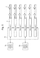
- FIG. 5 is an embodiment of a six channel, multiple redundant, fail-operative system architecture embodied in the processor 32.
- the system comprises a number of channels 5, each measuring transit time bi-directionally over the propagation path between a respective pair of transducers 3.
- Multiple redundant communication paths 16 ensure that in the event of a failure, all available measurement data can be routed over multiple redundant interfaces to external systems 7A and 7B.
- Each channel may also calculate derived air data parameters from the available measurement data and redundantly provide it to the external systems.
- transducers which can both receive and transmit
- pairs of transmitting and receiving transducers in place of a single bidirectional transducer although this is much less preferred as the paths between opposed receiving and transmitting transducers will not be exactly the same.
- the transducer pairs are sequentially activated at a frequency of about 300 Hz while the preferred ultrasonic frequency is about 235 kHz.
Landscapes
- Physics & Mathematics (AREA)
- Engineering & Computer Science (AREA)
- General Physics & Mathematics (AREA)
- Acoustics & Sound (AREA)
- Multimedia (AREA)
- Aviation & Aerospace Engineering (AREA)
- Radar, Positioning & Navigation (AREA)
- Remote Sensing (AREA)
- Measuring Volume Flow (AREA)
- Indicating Or Recording The Presence, Absence, Or Direction Of Movement (AREA)
Applications Claiming Priority (1)
| Application Number | Priority Date | Filing Date | Title |
|---|---|---|---|
| GB1320317.9A GB2520330B (en) | 2013-11-18 | 2013-11-18 | Ultrasonic airspeed and direction sensor system |
Publications (1)
| Publication Number | Publication Date |
|---|---|
| EP2873978A1 true EP2873978A1 (de) | 2015-05-20 |
Family
ID=49883775
Family Applications (1)
| Application Number | Title | Priority Date | Filing Date |
|---|---|---|---|
| EP20140181304 Withdrawn EP2873978A1 (de) | 2013-11-18 | 2014-08-18 | Ultraschallluftgeschwindigkeits- und -richtungssensor |
Country Status (3)
| Country | Link |
|---|---|
| US (1) | US9612252B2 (de) |
| EP (1) | EP2873978A1 (de) |
| GB (1) | GB2520330B (de) |
Families Citing this family (19)
| Publication number | Priority date | Publication date | Assignee | Title |
|---|---|---|---|---|
| CN104897925B (zh) * | 2015-06-24 | 2017-11-24 | 吉林大学 | 超声波风速风向测量装置及测量方法 |
| RU169800U1 (ru) * | 2016-08-23 | 2017-04-03 | Акционерное общество "ЛОМО" | Акустический анемометр |
| US10747217B1 (en) * | 2017-03-10 | 2020-08-18 | Rockwell Collins, Inc. | Distributed directional antenna |
| CN108226567A (zh) * | 2017-12-13 | 2018-06-29 | 太原航空仪表有限公司 | 一种利用流量传感器阵列实现小空速测量的方法 |
| CN111527411B (zh) * | 2018-01-19 | 2022-08-09 | 莱特拉姆有限责任公司 | 测量通过盘旋式输送机的气流的设备和方法 |
| US10884017B2 (en) * | 2018-03-23 | 2021-01-05 | Rosemount Aerospace Inc. | Acoustic angle-of-attack sensor |
| US11015955B2 (en) | 2018-06-15 | 2021-05-25 | Rosemount Aerospace Inc. | Dual channel air data system with inertially compensated backup channel |
| US10852316B2 (en) | 2018-06-15 | 2020-12-01 | Rosemount Aerospace Inc. | Advanced air data system architecture with air data computer incorporating enhanced compensation functionality |
| US10913545B2 (en) | 2018-06-15 | 2021-02-09 | Rosemount Aerospace Inc. | Architecture for providing enhanced altitude functionality to aircraft air data system |
| US10884016B2 (en) | 2018-07-13 | 2021-01-05 | Rosemount Aerospace Inc. | Low profile air data system architecture |
| US10739371B2 (en) | 2018-08-16 | 2020-08-11 | Rosemount Aerospace Inc. | Acoustic airspeed sensors |
| US10928413B2 (en) * | 2018-10-05 | 2021-02-23 | Rosemount Aerospace Inc. | Aircraft freestream data systems |
| US11154904B2 (en) * | 2018-10-12 | 2021-10-26 | Rosemount Aerospace Inc. | Acoustic sources for air data systems |
| CN109116363B (zh) * | 2018-10-30 | 2022-09-02 | 电子科技大学 | 一种换能器组距离可调的三维非正交超声波阵列测风装置 |
| US10900990B2 (en) * | 2019-03-21 | 2021-01-26 | Rosemount Aerospace Inc. | Acoustic air data sensing systems with skin friction sensors |
| US10837771B1 (en) | 2019-11-18 | 2020-11-17 | Rosemount Aerospace Inc. | Determining altitude of an aircraft during flight based on vortex shedding |
| US11016114B1 (en) * | 2020-02-11 | 2021-05-25 | Rosemount Aerospace Inc. | Determining aircraft flying conditions based on acoustic signals caused by airflow |
| US11467177B2 (en) | 2020-03-20 | 2022-10-11 | Rosemount Aerospace Inc. | Acoustic air data system with radially paired receivers |
| CN121410288A (zh) * | 2025-12-29 | 2026-01-27 | 浙江省应急管理科学研究院(浙江省安全生产技术检测检验中心、浙江省危险化学品登记中心) | 一种风速风向测量方法 |
Citations (4)
| Publication number | Priority date | Publication date | Assignee | Title |
|---|---|---|---|---|
| US4038870A (en) * | 1976-04-08 | 1977-08-02 | Honeywell Inc. | Air movement measuring apparatus |
| US4890488A (en) * | 1988-03-03 | 1990-01-02 | Simecsol | Ultrasonic anemometer |
| US5343744A (en) * | 1992-03-06 | 1994-09-06 | Tsi Incorporated | Ultrasonic anemometer |
| US20110043786A1 (en) * | 2009-06-23 | 2011-02-24 | Thales | Method of measuring the velocity of an aircraft by laser doppler anemometry |
Family Cites Families (12)
| Publication number | Priority date | Publication date | Assignee | Title |
|---|---|---|---|---|
| GB666413A (en) * | 1949-01-18 | 1952-02-13 | Ferranti Ltd | Improvements relating to apparatus for the measurement of the velocity of a moving body with respect to its surrounding fluid medium |
| US3222926A (en) * | 1961-07-10 | 1965-12-14 | Boeing Co | Air mass relative motion meter |
| US3246514A (en) * | 1964-02-28 | 1966-04-19 | Walter J Gremlitz | Single element electronic wind speed and direction sensor |
| US3633415A (en) * | 1969-03-28 | 1972-01-11 | Westinghouse Electric Corp | Flowmeter |
| US4031756A (en) * | 1976-08-02 | 1977-06-28 | Honeywell Inc. | Ultrasonic air movement and temperature measuring apparatus |
| US4262545A (en) * | 1979-03-21 | 1981-04-21 | The Bendix Corporation | Acoustic fluid velocity measuring system |
| US4391136A (en) * | 1981-06-18 | 1983-07-05 | The United States Of America As Represented By The Secretary Of The Navy | Three-axis current meter |
| FR2613078B1 (fr) * | 1987-03-26 | 1990-12-28 | Crouzet Sa | Dispositif de mesure de la vitesse air d'un helicoptere |
| US6601447B1 (en) * | 2002-05-16 | 2003-08-05 | The United States Of America As Represented By The Secretary Of The Army | Acoustic anemometer for simultaneous measurement of three fluid flow vector components |
| US8866322B2 (en) * | 2009-07-29 | 2014-10-21 | Michigan Aerospace Corporation | Atmospheric measurement system |
| CN201984080U (zh) * | 2011-01-26 | 2011-09-21 | 南京信息工程大学 | 移动式超声波风速风向仪 |
| CN102269769A (zh) * | 2011-05-13 | 2011-12-07 | 西南交通大学 | 超声波三维测风方法和三维超声波风速风向仪 |
-
2013
- 2013-11-18 GB GB1320317.9A patent/GB2520330B/en active Active
-
2014
- 2014-08-18 EP EP20140181304 patent/EP2873978A1/de not_active Withdrawn
- 2014-11-05 US US14/533,794 patent/US9612252B2/en active Active
Patent Citations (4)
| Publication number | Priority date | Publication date | Assignee | Title |
|---|---|---|---|---|
| US4038870A (en) * | 1976-04-08 | 1977-08-02 | Honeywell Inc. | Air movement measuring apparatus |
| US4890488A (en) * | 1988-03-03 | 1990-01-02 | Simecsol | Ultrasonic anemometer |
| US5343744A (en) * | 1992-03-06 | 1994-09-06 | Tsi Incorporated | Ultrasonic anemometer |
| US20110043786A1 (en) * | 2009-06-23 | 2011-02-24 | Thales | Method of measuring the velocity of an aircraft by laser doppler anemometry |
Also Published As
| Publication number | Publication date |
|---|---|
| US9612252B2 (en) | 2017-04-04 |
| GB201320317D0 (en) | 2014-01-01 |
| GB2520330B (en) | 2017-04-19 |
| US20150135822A1 (en) | 2015-05-21 |
| GB2520330A (en) | 2015-05-20 |
Similar Documents
| Publication | Publication Date | Title |
|---|---|---|
| US9612252B2 (en) | Ultrasonic airspeed and direction sensor system | |
| EP0824669B1 (de) | System zur ermittlung der eigenschaften einer gas- oder flüssigkeitströmung | |
| US6590520B1 (en) | Method and system for determining air turbulence using bi-static measurements | |
| EP3739343B1 (de) | Luftdatensystemarchitekturen mit laserluftdaten- und akustischen luftdatensensoren | |
| CN101793594A (zh) | 空气动力学测量探测器及装配有所述探测器的直升机 | |
| EP3693746B1 (de) | Akustisches luftdatensystem | |
| EP3611517B1 (de) | Akustische luftgeschwindigkeitssensoren | |
| EP3594696B1 (de) | Luftdatensystemarchitektur mit niedrigem profil | |
| WO2016103464A1 (ja) | 障害物検知装置及び障害物検知方法 | |
| WO2018195385A1 (en) | Acoustic structural reflection interference mitigation systems, methods, and devices | |
| JP2021063741A (ja) | 飛行体用対気速度及び風向計測装置及びその計測方法 | |
| EP3543711A1 (de) | Akustischer anstellwinkelsensor | |
| EP3712620B1 (de) | System zur erfassung akustischer luftdaten mit oberflächenreibungssensor | |
| EP3995835B1 (de) | Akustische luftgeschwindigkeitssensoren und verarbeitungstechniken | |
| EP3133402B1 (de) | Sensorsystem zur bestimmung von luftgeschwindigkeiten | |
| EP3882639B1 (de) | Akustisches luftdatensystem mit radial gepaarten empfängern | |
| RU2592705C2 (ru) | Бортовая система измерения параметров вектора скорости ветра на стоянке, стартовых и взлетно-посадочных режимах вертолета | |
| US11614460B2 (en) | Ultrasound air-speed indicator | |
| JP7452275B2 (ja) | 水流発電システム及び航走体 | |
| JP2022065535A (ja) | 飛行体用対気速度及び風向計測装置、計測方法並びに計測プログラム | |
| RU2548299C2 (ru) | Система измерения параметров динамики атмосферы в приземном слое | |
| JP6755407B2 (ja) | 複数の超音波変換器を校正するための方法およびこの方法を実行するための装置 | |
| HK1002969B (en) | System for determination of fluid flow parameters | |
| WO2025244726A1 (en) | Method for determining watercraft bearing and speed from wave wake observation | |
| RU131505U1 (ru) | Система измерения параметров динамики атмосферы в приземном слое |
Legal Events
| Date | Code | Title | Description |
|---|---|---|---|
| PUAI | Public reference made under article 153(3) epc to a published international application that has entered the european phase |
Free format text: ORIGINAL CODE: 0009012 |
|
| 17P | Request for examination filed |
Effective date: 20140818 |
|
| AK | Designated contracting states |
Kind code of ref document: A1 Designated state(s): AL AT BE BG CH CY CZ DE DK EE ES FI FR GB GR HR HU IE IS IT LI LT LU LV MC MK MT NL NO PL PT RO RS SE SI SK SM TR |
|
| AX | Request for extension of the european patent |
Extension state: BA ME |
|
| STAA | Information on the status of an ep patent application or granted ep patent |
Free format text: STATUS: THE APPLICATION IS DEEMED TO BE WITHDRAWN |
|
| 18D | Application deemed to be withdrawn |
Effective date: 20151121 |