EP2873987B1 - Radarsystem und datenverarbeitungsvorrichtung - Google Patents
Radarsystem und datenverarbeitungsvorrichtung Download PDFInfo
- Publication number
- EP2873987B1 EP2873987B1 EP12881094.2A EP12881094A EP2873987B1 EP 2873987 B1 EP2873987 B1 EP 2873987B1 EP 12881094 A EP12881094 A EP 12881094A EP 2873987 B1 EP2873987 B1 EP 2873987B1
- Authority
- EP
- European Patent Office
- Prior art keywords
- data
- image
- temporary
- moving object
- temporary image
- Prior art date
- Legal status (The legal status is an assumption and is not a legal conclusion. Google has not performed a legal analysis and makes no representation as to the accuracy of the status listed.)
- Active
Links
Images
Classifications
-
- G—PHYSICS
- G01—MEASURING; TESTING
- G01S—RADIO DIRECTION-FINDING; RADIO NAVIGATION; DETERMINING DISTANCE OR VELOCITY BY USE OF RADIO WAVES; LOCATING OR PRESENCE-DETECTING BY USE OF THE REFLECTION OR RERADIATION OF RADIO WAVES; ANALOGOUS ARRANGEMENTS USING OTHER WAVES
- G01S7/00—Details of systems according to groups G01S13/00, G01S15/00, G01S17/00
- G01S7/02—Details of systems according to groups G01S13/00, G01S15/00, G01S17/00 of systems according to group G01S13/00
- G01S7/28—Details of pulse systems
- G01S7/285—Receivers
- G01S7/295—Means for transforming co-ordinates or for evaluating data, e.g. using computers
-
- G—PHYSICS
- G01—MEASURING; TESTING
- G01S—RADIO DIRECTION-FINDING; RADIO NAVIGATION; DETERMINING DISTANCE OR VELOCITY BY USE OF RADIO WAVES; LOCATING OR PRESENCE-DETECTING BY USE OF THE REFLECTION OR RERADIATION OF RADIO WAVES; ANALOGOUS ARRANGEMENTS USING OTHER WAVES
- G01S13/00—Systems using the reflection or reradiation of radio waves, e.g. radar systems; Analogous systems using reflection or reradiation of waves whose nature or wavelength is irrelevant or unspecified
- G01S13/88—Radar or analogous systems specially adapted for specific applications
- G01S13/89—Radar or analogous systems specially adapted for specific applications for mapping or imaging
- G01S13/90—Radar or analogous systems specially adapted for specific applications for mapping or imaging using synthetic aperture techniques, e.g. synthetic aperture radar [SAR] techniques
- G01S13/9004—SAR image acquisition techniques
- G01S13/9011—SAR image acquisition techniques with frequency domain processing of the SAR signals in azimuth
-
- G—PHYSICS
- G01—MEASURING; TESTING
- G01S—RADIO DIRECTION-FINDING; RADIO NAVIGATION; DETERMINING DISTANCE OR VELOCITY BY USE OF RADIO WAVES; LOCATING OR PRESENCE-DETECTING BY USE OF THE REFLECTION OR RERADIATION OF RADIO WAVES; ANALOGOUS ARRANGEMENTS USING OTHER WAVES
- G01S7/00—Details of systems according to groups G01S13/00, G01S15/00, G01S17/00
- G01S7/02—Details of systems according to groups G01S13/00, G01S15/00, G01S17/00 of systems according to group G01S13/00
- G01S7/40—Means for monitoring or calibrating
-
- G—PHYSICS
- G06—COMPUTING OR CALCULATING; COUNTING
- G06T—IMAGE DATA PROCESSING OR GENERATION, IN GENERAL
- G06T3/00—Geometric image transformations in the plane of the image
- G06T3/40—Scaling of whole images or parts thereof, e.g. expanding or contracting
- G06T3/4053—Scaling of whole images or parts thereof, e.g. expanding or contracting based on super-resolution, i.e. the output image resolution being higher than the sensor resolution
-
- G—PHYSICS
- G06—COMPUTING OR CALCULATING; COUNTING
- G06T—IMAGE DATA PROCESSING OR GENERATION, IN GENERAL
- G06T2207/00—Indexing scheme for image analysis or image enhancement
- G06T2207/10—Image acquisition modality
- G06T2207/10032—Satellite or aerial image; Remote sensing
- G06T2207/10044—Radar image
-
- G—PHYSICS
- G06—COMPUTING OR CALCULATING; COUNTING
- G06T—IMAGE DATA PROCESSING OR GENERATION, IN GENERAL
- G06T2207/00—Indexing scheme for image analysis or image enhancement
- G06T2207/30—Subject of image; Context of image processing
- G06T2207/30181—Earth observation
-
- G—PHYSICS
- G06—COMPUTING OR CALCULATING; COUNTING
- G06T—IMAGE DATA PROCESSING OR GENERATION, IN GENERAL
- G06T2210/00—Indexing scheme for image generation or computer graphics
- G06T2210/36—Level of detail
Definitions
- the present invention relates to a radar system mounted on a moving object, such as a satellite, and that observe an object such as the Earth surface and to a data processing device.
- a synthetic aperture radar (SAR: Synthetic Aperture Radar) is a device that is mounted on a moving object, such as a satellite or an airplane, and that observes an object, such as the Earth surface, with a high resolution.
- This radar usually emits a radio wave in a direction nearly perpendicular to the direction of movement of the moving object.
- the radar carries out the observation on a region on the ground to which the radio wave is applied thereby acquiring an image with a resolution in a direction parallel to the direction of movement of the moving object through a synthetic aperture process, and also acquiring an image with a resolution in a direction of emitting the radio wave (range direction) through a pulse compression process.
- the synthetic aperture process is the one of improving the angular resolution.
- the angular resolution of the radar is determined by the size of the antenna which is used when emitting the radio wave to space, and the larger aperture the antenna has, the higher angular resolution is acquired.
- a SAR provides an angular resolution equivalent to that of an antenna having an aperture of the same size as the length of a moving path by carrying out observation while moving, and combining received signals which are acquired during a fixed time period by performing signal processing.
- patent reference 1 an example of the signal processing method is shown in patent reference 1. In this patent reference 1, in order to acquire a high resolution image, high-accuracy signal processing in consideration of the satellite's orbit being a curved line is carried out.
- Patent reference 1 Japanese Unexamined Patent Application Publication No. 2011-169869
- a Doppler frequency analysis is performed on a received signal to acquire an angular resolution. More specifically, when observing an identical target point for a long time, the relative velocity between the radar and the target point varies during the observation time period. As a result, the received signal of the target point has a Doppler frequency bandwidth corresponding to the amount of change of the relative velocity. Because the amount of information about an angle at which the target exists increases with increase in this Doppler frequency width, the angular resolution is improved with increase in this Doppler frequency width.
- a SAR carries out a pulse compression process in order to acquire a range resolution. Therefore, the radio wave is emitted in a pulse form. More specifically, a SAR is a pulsed Doppler radar that emits a pulse wave. Therefore, a Doppler frequency analysis for acquiring an angular resolution is carried on received signals discrete with a pulse repetition frequency (PRF).
- PRF pulse repetition frequency
- a SAR mounted in, for example, a satellite carries out data transmission of the received signal from the satellite to a ground station, and the ground station carries out an image reconstruction process.
- the image reconstruction process performed by a SAR requires a huge amount of computation, and, conventionally, it is difficult for a computer which can be mounted in the satellite to carry out the image reconstruction.
- the performance of computers has been improving generally, and computers having computing power which enables even a satellite-mounted SAR to carry out image reconstruction on the satellite have been provided.
- the received signal may be transmitted to a ground station after a data compression process is performed on the received signal. Because the signal on which no image reconstruction process has been performed yet has a high random nature, a constraint is placed on an improvement in the efficiency of data compression. In contrast, because the random nature of the image data is reduced when image reconstruction is carried out on the satellite, the efficiency of data compression can be improved.
- JP 2010 236970 A refers to a generation device, reproduction device, generation program, reproduction program, generation method, and reproduction method of SAR superimposed data.
- an SAR/optical observation satellite (1) the same area on the ground is observed by the SAR and the optical sensor, and (2) superimposed data acquired by superimposing observation data by the SAR on observation data by the optical sensor are generated by an SAR/optical transmission device, and (3) the superimposed data are downlinked.
- the SAR image and the optical image are reproduced from the superimposed data by a SAR/optical reproduction device.
- the SAR/optical transmission device per-forms reverse processing of SAR reproduction processing to the optical image imaged by the optical sensor 112, encodes the reversely-processed optical image, and generates observation data of the optical sensor.
- US 4,989,008 refers to a spotlight mapping radar system.
- the receiving apparatus of a spotlight mapping radar system is provided with a digital beamforming antenna capable of converting the echo signals received by a plurality of antenna elements into corresponding digital signals and processing them by DFT and forming a plurality of reception beams oriented in different directions at the same time to enhance the cross-range resolution without reducing the distance measurement capability and the measurable range.
- Pulse compressors, azimuth compressors, display buffers and reference signal generators are provided respectively for each of the outputs of the digital beamforming antenna for outputting the plurality of reception beams.
- An output picture synthesizing apparatus synthesizes signals representing the picture information from the respective display buffers and outputs the synthesized signals to a display to display thereon the synthesized picture of an object to be observed.
- JP 2008 177768 A refers to an image transmitting device.
- the image transmitting device is provided with: a detection range determination means for specifying the detection object range of an image from a target existing range obtained from the position assessment result or direction measurement result of a radio wave tracing device; a template extraction means for specifying an image target from target identification candidates obtained from the radio wave tracing device; a detail target position calculation means for calculating a detail target position from the specification result and pickup image of the detection range determination means and the template extraction means; an adaptive compression parameter calculation means for calculating the optimal image compression parameter from an image output rate and an applied radio transmission speed; and an adaptive image compression means for performing image compression from the calculation result of the detail target position calculation means and the optimal image compression parameter of the adaptive compression parameter calculation means.
- a method of compressing phase history (PH) data includes (a) dividing PH data into multiple sub-apertures; (b) transforming the sub-apertures into multiple coarse resolution images; and (c) compressing each of the coarse resolution images. Compressing each of the coarse resolution images may include (i) selecting at least one image from the coarse resolution images to form a base image, (ii) differencing each of the coarse resolution images from the base image to form residual images, and (iii) quantizing the residual images.
- the present invention is made in order to solve the above-mentioned problems, and it is therefore an object of the present invention to provide a radar system and a data processing device that can acquire an image without degradation of a resolution while reducing the amount of data transmission.
- a radar system including an observation device (1) that is mounted on a moving object, such as a satellite, and observes a target, and a data processing device (2), installed in a data receiving facility such as a ground station, a ship or a plane, that processes data from the observation device, wherein said observation device (1) comprises:
- the radar system in accordance with the present invention is constructed as above, the radar system can acquire the image without degradation in the resolution while reducing the amount of data transmission.
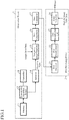
- Fig. 1 is a block diagram showing the structure of a radar system in accordance with Embodiment 1 of the present invention.
- the radar system is comprised of an observation device 1 and a data processing device 2, as shown in Fig. 1 .
- the observation device 1 is mounted in a moving object, and observes an object.
- This observation device 1 is comprised of a transmitter 11, a transmission/reception switch 12, an antenna 13, a receiver 14, a temporary image generator 15, a data compressor 16, and a data transmitter 17.
- the transmitter 11 generates a predetermined pulse-shaped radar wave.
- the radar wave generated by this transmitter 11 is outputted to the transmission/reception switch 12.
- the transmission/reception switch 12 selectively changes the output destination of an input wave.
- This transmission/reception switch 12 outputs the radar wave from the transmitter 11 to space from the antenna 13, and outputs a radar wave from the antenna 13 to the receiver 14.
- the observation device emits the radar wave from the antenna 13 and the transmission/reception switch 12 to outside the radar system (space), and also receives a part of the radar wave (scattered wave) scattered by an object (observation target) outside the radar system.
- the radar wave received by this antenna 13 is outputted to the transmission/reception switch 12.
- the receiver 14 receives the radar wave from the transmission/reception switch 12.
- the receiver 14 then amplifies the radar wave and converts this radar wave into a received signal having a low frequency through frequency conversion.
- the received signal converted by this receiver 14 is outputted to the temporary image generator 15.
- the transmitter 11, the transmission/reception switch 12, the antenna 13, and the receiver 14 construct a transmitter and receiver in accordance with the present invention.
- the temporary image generator 15 generates a temporary image (low resolution image) on the basis of the received signal from the receiver 14.
- the temporary image generated by this temporary image generator 15 is outputted to the data compressor 16.
- the data compressor 16 performs a data compression process on the temporary image from the temporary image generator 15, and generates compressed image data.
- the compressed image data generated by this data compressor 16 is outputted to the data transmitter 17.
- the data transmitter 17 transmits the compressed image data from the data compressor 16 to the data processing device 2 at a remote location.
- the data processing device 2 is mounted in a data reception facility, and processes the data from the observation device 1.
- the data reception facility is typically a ground station.
- the data reception facility is not limited to a ground station.
- the data reception facility can be held by a ship, an airplane, or the like.
- This data processing device 2 is comprised of a data receiver 21, a data decompressor 22, a data reconstruction unit 23, and an image generator 24.
- the data receiver 21 receives the compressed image data from the data transmitter 17 of the observation device 1.
- the compressed image data received by this data receiver 21 is outputted to the data decompressor 22.
- the data decompressor 22 decompresses the compressed image data from the data receiver 21 to acquire the original temporary image.
- the temporary image acquired by this data decompressor 22 is outputted to the data reconstruction unit 23.
- the data reconstruction unit 23 carries out a process inverse to an azimuth compression process in an image reconstruction process by the temporary image generator 15 on the temporary image from the data decompressor 22 to temporarily return the temporary image to a signal on which no azimuth compression has been performed yet.
- the image which is returned to the signal, on which no azimuth compression has been performed yet, by this data reconstruction unit 23 is outputted to the image generator 24.
- the image generator 24 generates an image having a higher resolution than that generated by the temporary image generator 15 on the basis of the image from the data reconstruction unit 23 by using high-accuracy orbit data about the moving object in which the observation device 1 is mounted.
- the image generated by this image generator 24 is outputted to outside the radar system.
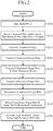
- the transmitter 11 In the operation of the radar system, the transmitter 11 generates a predetermined pulse-shaped radar wave first, and emits this radar wave to outside the radar system from the antenna 13 by way of the transmission/reception switch 12, as shown in Fig. 2 (step ST1).
- the antenna 13 receives a part of the radar wave (scattered wave) scattered by an object existing outside the radar system, and outputs the part to the receiver 14 by way of the transmission/reception switch 12.
- the receiver 14 then amplifies this radar wave, and also converts the radar wave into a received signal having a low frequency through frequency conversion (step ST2).
- the received signal received and converted by this receiver 14 is outputted to the temporary image generator 15.
- the temporary image generator 15 then generates a temporary image on the basis of the received signal from the receiver 14 (step ST3).
- a received signal is acquired on two-dimensional space which is defined by two axes including a range axis and an azimuth axis.
- an image which is blurred both in a direction of the range axis and in a direction of the azimuth axis is provided. Therefore, the temporary image generator 15 improves the range resolution by performing a pulse compression process, and improves the azimuth resolution by performing an azimuth compression process.
- the pulse compression process and the azimuth compression process typically consist of a data compensation process and a coherent integration process in a direction of the azimuth axis.
- the data compensation process is carried out on the azimuth axis and a case in which data is converted into data on an azimuth frequency axis by using a Fourier transform, and the data compensation process is carried out on the data.
- a Fourier transform is typically used for an improvement in the efficiency of computation.
- the data compressor 16 then performs the data compression process on the temporary image from the temporary image generator 15 to generate compressed image data (step ST4).
- the data size of the compressed image data becomes smaller than the data size of the original image.
- the type of the data compression method is not limited particularly, and a method known typically can be used as the data compression method. For example, compression according to JPEG can be carried out.
- the compressed image data generated by this data compressor 16 is outputted to the data transmitter 17.
- the data transmitter 17 then transmits the compressed image data from the data compressor 16 to the data processing device 2 at a remote location (step ST5). More specifically, the compressed image data is transmitted from the observation device 1 mounted in the moving object to the data processing device 2 installed in a data reception facility placed at a remote location by the data transmitter 17. This transmission can be carried out by using a data transmission method which is the same as that for use in typical SAR satellites.
- the data receiver 21 of the data processing device 2 then receives the compressed image data from the data transmitter 17 of the observation device 1 (step ST6) .
- the compressed image data received by this data receiver 21 is outputted to the data decompressor 22.
- the data decompressor 22 then decompresses the compressed image data from the data receiver 21 to acquire the original temporary image (step ST7).
- the data compression method used by the data compressor 16 is lossless compression
- the temporary image acquired by the data decompressor 22 is completely the same as the temporary image generated by the temporary image generator 15.
- noise occurring due to the compression is added to the temporary image acquired by the data decompressor 22.
- the temporary image acquired by this data decompressor 22 is outputted to the data reconstruction unit 23.
- the data reconstruction unit 23 then carries out a process inverse to the azimuth compression process in the image reconstruction process by the temporary image generator 15 on the temporary image from the data decompressor 22 to temporarily return the temporary image to a signal on which no azimuth compression has been performed yet (step ST8).
- a method called a chirp scaling method is used by the temporary image generator 15.
- image reconstruction is carried out by using a multiplication of a Fourier transform by a phase compensation coefficient. Therefore, the data reconstruction unit 23 carries out an inverse Fourier transform and also acquires a signal on which no azimuth compression has been performed yet by dividing the phase value by which a Fourier transform is multiplied by the temporary image generator 15.
- the temporary image generator 15 enters a state in which the temporary image generator is called when low-accuracy orbit data is used. The image reconstructed by this data reconstruction unit 23 is outputted to the image generator 24.
- the image generator 24 then carries out the azimuth compression process on the temporary image from the data reconstruction unit 23 by using high-accuracy orbit data about the moving object to generate a high resolution image (step ST9) . More specifically, the image generator carries out a high-accuracy image reconstruction process on the acquired signal on which no azimuth compression has been performed yet (carries out an azimuth compression process with a higher azimuth resolution than that of the azimuth compression process performed by the temporary image generator 15) to generate a high resolution image. In this high-accuracy image reconstruction process, orbit data having a higher degree of accuracy than that of the simple orbit data for use in the temporary image generator 15 is used.
- the radar system in accordance with this Embodiment 1 is constructed in such a way as to generate an image on a moving object, the data compression efficiency at the time of carrying out data transmission from the moving object to the data reception facility can be increased and the amount of data transmission can be reduced. As a result, the radar system can carry out the data transmission in a short time. Further, the radar system can carry out the data transmission even when using the data transmitter 17 and the data receiver 21 having a low data transmission ability. For example, because the antenna gains of the data transmitter 17 and the data receiver 21 can be made small, the antenna size can be downsized. Further, because the radar system carries out the image reconstruction process by using the high-accuracy orbit data also after data transmission, the radar system can acquire an image having a high resolution.
- the radar system in accordance with Embodiment 1 is constructed in such a way that after carrying out data compression on the image, the data compressor 16 of the observation device 1 transmits the image to the data processing device 2, and the data decompressor 22 of the data processing device 2 decompresses the compressed data to extract the original image, the data compressor 16 and the data decompressor 22 can be omitted and the temporary image generated by the temporary image generator 15 can be transmitted to the data processing device 2 just as it is.
- the image reconstruction process including the azimuth compression process, the pulse compression process, or both of these processes, the data size after the process becomes smaller than the data size before the process even when no data compression is carried out. Therefore, by causing the observation device to carry out these processes, the radar system can reduce the amount of data transmission even when carrying out no data compression.
- Embodiment 1 the structure of, after the data processing device 2 receives the image generated by the observation device 1, temporarily returning the image to a signal on which no azimuth compression has been performed yet by using the data reconstruction unit 23 is shown.
- Embodiment 2 a case in which an observation device 1 carries out azimuth compression part way through, and a data processing device 2 carries out the remaining part of the azimuth compression process is shown.
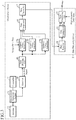
- Fig. 3 is a block diagram showing the structure of a radar system in accordance with Embodiment 2 of the present invention. In the radar system in accordance with Embodiment 2 shown in this Fig. 3 , the temporary image generator 15 of the radar system in accordance with Embodiment 1 shown in Fig.
- Embodiment 1 is replaced by a data dividing unit 18 and a plurality of temporary image generators 15b, and the data reconstruction unit 23 and the image generator 24 of the radar system in accordance with Embodiment 1 are replaced by a data combining unit (image generator) 25.
- the other structural components are the same as those of the radar system in accordance with Embodiment 1 and are designated by the same reference numerals, and the explanation of the other structural components will be omitted hereafter.
- the data dividing unit 18 divides a received signal from a receiver 14 into a plurality of sections in a temporal direction, and outputs these sections to the plurality of temporary image generators 15b respectively.
- the plurality of temporary image generators 15b generate a plurality of temporary images (low resolution images) on the basis of the received signals about the plurality of sections from the data dividing unit 18 respectively.
- Each of the temporary images generated by these temporary image generators 15b is outputted to a data compressor 16.
- the data combining unit 25 generates a single high resolution image by combining a plurality of temporary images from a data decompressor 22.
- the image generated by this data combining unit 25 is outputted to outside the radar system.
- the radar system in accordance with this embodiment is constructed in such a way that the execution of an image reconstruction method, which is known as a subaperture method, is shared between the observation device 1 and the data processing device 2.
- the subaperture method is disclosed in, for example, patent reference 1.
- a received signal acquired during a synthetic aperture is divided into sections in a temporal direction first.
- reconstruction of a low resolution temporary image is carried out on a signal in each small section after division by each temporary image generator 15b. Because the process carried out at this time is azimuth compression in a short synthetic aperture time, the azimuth resolution is low. Because each temporary image has a low resolution, the accuracy of orbit data used at this time (temporary orbit data acquired on an orbit) can be lower than that of orbit data for use in the data processing device 2 which will be mentioned below.
- the data compressor 16 collectively carries out data compression on the plurality of temporary images generated by the plurality of temporary image generators 15b.
- data compression can be carried out on this single data, or data compression can be carried out on each of the temporary images and the plurality of data compressed can be combined into single data.
- the data volume after the imaging becomes smaller than that before the imaging. Further, because the imaging is carried out, the efficiency of the data compression becomes high. As a result, it is expected that the data size becomes smaller than that in a case of transmitting a yet-to-be-processed received signal.
- the compressed data is returned to data when outputted from the temporary image generators 15b, i.e., the plurality of temporary images by way of a data transmitter 17, a data receiver 21, and the data decompressor 22.
- the data combining unit 25 combines the plurality of temporary images to generate a single high resolution image. Because a concrete processing procedure is the same as that disclosed by patent reference 1, the concrete processing procedure will be not described in detail. In order to make the image generated in this embodiment have a high resolution, orbit data having a higher degree of accuracy than that required in the above-mentioned process carried out in the observation device 1 is required.
- the amount of data transmission from the observation device 1 to the data processing device 2 can be reduced because the observation device 1 in accordance with this Embodiment 2 carries out up to the temporary imaging process, and a high resolution image can be acquired because the data processing device 2 in accordance with this Embodiment 2 carries out the signal processing.
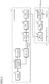
- Fig. 4 is a block diagram showing the structure of a radar system in accordance with the present example.
- the temporary image generator 15 of the radar system in accordance with Embodiment 1 shown in Fig. 1 is replaced by a pulse compression unit (temporary image generator) 19 and the image generator 24 of the radar system in accordance with Embodiment 1 is replaced by an azimuth compressing unit (image generator) 26, and the data reconstruction unit 23 is removed.
- the other structural components are the same as those of the radar system in accordance with Embodiment 1 and are designated by the same reference numerals, and the explanation of the other structural components will be omitted hereafter.
- the pulse compression unit 19 generates a temporary image having a high range resolution by carrying out only the pulse compression process on the basis of a received signal from a receiver 14.
- the temporary image generated by this pulse compression unit 19 is outputted to a data compressor 16.
- the data compressor 16 performs a data compression process on the temporary image from the pulse compression unit 19 to generate compressed image data.
- a high resolution image is acquired in a direction of a range axis by this pulse compression unit 19.
- the data volume is reduced by a pulse width also before the data compression is carried out.
- the improvement in the range resolution causes an increase in the efficiency of the data compression by the data compressor 16.
- the observation device 1 mounted in the moving object does not need any orbit data.
- the azimuth compressing unit 26 carries out an azimuth compression process for improving the azimuth resolution on the basis of the temporary image from the data decompressor 22 by using the orbit data about the moving object to generate a high resolution image.
- the image generated by this azimuth compressing unit 26 is outputted to outside the radar system.
- the radar system in accordance with this example is constructed in such a way as to, when generating a temporary image on the moving object, carry out only the pulse compression process. Even in this example there can be provided the same advantages as those provided by Embodiment 1.
- 1 observation device 2 data processing device, 11 transmitter, 12 transmission/reception switch, 13 antenna, 14 receiver, 15 and 15b temporary image generator, 16 data compressor, 17 data transmitter, 18 data dividing unit, 19 pulse compression unit, 21 data receiver, 22 data decompressor, 23 data reconstruction unit, 24 image generator, 25 data combining unit, 26 azimuth compressing unit.
Landscapes
- Engineering & Computer Science (AREA)
- Remote Sensing (AREA)
- Radar, Positioning & Navigation (AREA)
- Physics & Mathematics (AREA)
- General Physics & Mathematics (AREA)
- Computer Networks & Wireless Communication (AREA)
- Electromagnetism (AREA)
- Signal Processing (AREA)
- Theoretical Computer Science (AREA)
- Radar Systems Or Details Thereof (AREA)
- Compression, Expansion, Code Conversion, And Decoders (AREA)
Claims (4)
- Radarsystem mit einer Beobachtungseinrichtung (1), die an einem sich bewegenden Objekt, wie einem Satelliten, angebracht ist, und ein Ziel beobachtet, und einer Datenverarbeitungseinrichtung (2), die in einer Datenempfangsanlage, wie einer Bodenstation, einem Schiff oder einem Flugzeug installiert ist, die Daten von der Beobachtungseinrichtung verarbeitet, wobei die Beobachtungseinrichtung (1) umfasst:einen Sender und Empfänger (11, 14), der eine vorherbestimmte Radarwelle nach außerhalb des Radarsystems aussendet, und der die durch das Ziel gestreute Radarwelle empfängt und ein empfangenes Signal erwirbt;einen Erzeuger temporärer Bilder (15; 15b), der einen Azimutkomprimierungsprozess auf das durch den Sender und Empfänger erworbene empfangene Signal temporär durchführt unter Verwendung von temporären Orbitdaten über das sich bewegende Objekt, um ein temporäres Bild, das ein Bild mit geringer Auflösung ist, zu erzeugen;einen Datenkomprimierer (16), der einen Datenkomprimierungsprozess auf das temporäre Bild vom Erzeuger temporärer Bilder (15, 15b) durchführt und komprimierte Bilddaten erzeugt; undeinen Datenübertrager (17), der die komprimierten Bilddaten vom Datenkomprimierer (16) an die entfernte Datenverarbeitungseinrichtung (2) überträgt, und wobeidie Datenverarbeitungseinrichtung (2) umfasst:einen Datenempfänger (21), der die durch den Datenübertrager (17) übertragenen komprimierten Bilddaten empfängt;einen Datenkomprimierer (22), der die komprimierten Bilddaten vom Datenempfänger (21) dekomprimiert, um das ursprüngliche temporäre Bild zu erwerben;eine Datenrekonstruktionseinheit (23), die einen zum Azimutkomprimierungsprozess inversen Prozess auf das empfangene temporäre Bild durchführt, um das temporäre Bild zu einem Signal, auf das keine Azimutkomprimierung durchgeführt wird, temporär zurückzuführen, und das Signal ausgibt; undeinen Bilderzeuger (24), der einen Azimutkomprimierungsprozess auf das von der Datenrekonstruktionseinheit (23) empfangene Signal durchführt, um ein Bild zu erzeugen unter Verwendung von Orbitdaten über das sich bewegende Objekt mit einem höheren Genauigkeitsgrad als die temporären Orbitdaten über das sich bewegende Objekt.
- Radarsystem nach Anspruch 1, wobei der Erzeuger temporärer Bilder (15b) das empfangene Signal in eine Vielzahl von Abschnitten in einer zeitlichen Richtung unterteilt und eine Vielzahl von temporären Bildern erzeugt unter Verwendung empfangener Signalteile, die jeweils den Abschnitten entsprechen, und der Bilderzeuger (25) ein Bild erzeugt durch Kombinieren der Vielzahl von temporären Bildern.
- Beobachtungseinrichtung (1), die an einem sich bewegenden Objekt, wie einem Satelliten, angebracht ist, und ein Ziel beobachtet, wobei die Beobachtungseinrichtung (1), umfasst:einen Sender und Empfänger (11, 14), der eine vorherbestimmte Radarwelle nach außerhalb der Beobachtungseinrichtung (1) aussendet und der die durch das Ziel gestreute Radarwelle empfängt und ein empfangenes Signal erwirbt;einen Erzeuger temporärer Bilder (15; 15b), der einen Azimutkomprimierungsprozess auf das durch den Sender und Empfänger (11, 14) erworbene empfangene Signal temporär durchführt unter Verwendung temporärer Orbitdaten über das sich bewegende Objekt, um ein temporäres Bild, das ein Bild mit geringer Auflösung ist, zu erzeugen;einen Datenkomprimierer (16), der einen Datenkomprimierungsprozess auf das temporäre Bild vom Erzeuger temporärer Bilder (15, 15b) durchführt und komprimierte Bilddaten erzeugt; undeinen Datenübertrager (17), der das komprimierte temporäre Bild an eine Datenverarbeitungseinrichtung (2) an einem entfernten Standort überträgt; wobei die Datenverarbeitungseinrichtung (2) die komprimierten Bilddaten empfängt und dekomprimiert und einen zum Azimutkomprimierungsprozess inversen Prozess auf das ursprüngliche temporäre Bild durchführt, um das temporäre Bild zu einem Signal, auf das keine Azimutkomprimierung durchgeführt wird, temporär zurückzuführen, das Signal ausgibt, und dann einen Azimutkomprimierungsprozess auf das Signal durchführt, um ein Bild zu erzeugen unter Verwendung von Orbitdaten über das sich bewegende Objekt mit einem höheren Genauigkeitsgrad als die temporären Orbitdaten über das sich bewegende Objekt.
- Datenverarbeitungseinrichtung (2), die in einer Datenempfangsanlage, wie einer Bodenstation, einem Schiff oder einem Flugzeug, installiert ist, die Daten von einer Beobachtungseinrichtung (1), die an einem sich bewegenden Objekt, wie einem Satelliten, angebracht ist, verarbeitet und ein Ziel beobachtet, wobei die Datenverarbeitungseinrichtung (2), umfasst:einen Datenempfänger (21), der komprimierte Bilddaten eines temporären Bildes empfängt,einen Datendekomprimierer (22), der die komprimierten Bilddaten dekomprimiert, um das ursprüngliche temporäre Bild zu erwerben, wobei das temporäre Bild ein Bild mit geringer Auflösung ist, das die Beobachtungseinrichtung (1) erzeugt durch Empfangen einer vorherbestimmten Radarwelle, die die Beobachtungseinrichtung (1) zur Außenseite emittiert und die nach Streuung durch das Ziel zurückempfangen wird, wobei die Beobachtungseinrichtung (1) ferner einen temporären Azimutkomprimierungsprozess auf das empfangene Signal durchführt unter Verwendung temporärer Orbitdaten über das sich bewegende Objekt;eine Datenrekonstruktionseinheit (23), die einen zum Azimutkomprimierungsprozess inversen Prozess auf das empfangene temporäre Bild durchführt, um das temporäre Bild zu einem Signal, auf das keine Azimutkomprimierung durchgeführt wird, temporär zurückzuführen, und das Signal ausgibt; undeinen Bilderzeuger (24), der einen Azimutkomprimierungsprozess auf das von der Datenrekonstruktionseinheit (23) empfangene Bild durchführt, um ein Bild zu erzeugen unter Verwendung von Orbitdaten über die das sich bewegende Objekt mit einem höheren Genauigkeitsgrad als die temporären Orbitdaten über das sich bewegende Objekt.
Applications Claiming Priority (1)
| Application Number | Priority Date | Filing Date | Title |
|---|---|---|---|
| PCT/JP2012/004511 WO2014010000A1 (ja) | 2012-07-12 | 2012-07-12 | レーダシステムおよびデータ処理装置 |
Publications (3)
| Publication Number | Publication Date |
|---|---|
| EP2873987A1 EP2873987A1 (de) | 2015-05-20 |
| EP2873987A4 EP2873987A4 (de) | 2016-03-09 |
| EP2873987B1 true EP2873987B1 (de) | 2019-07-03 |
Family
ID=49915504
Family Applications (1)
| Application Number | Title | Priority Date | Filing Date |
|---|---|---|---|
| EP12881094.2A Active EP2873987B1 (de) | 2012-07-12 | 2012-07-12 | Radarsystem und datenverarbeitungsvorrichtung |
Country Status (4)
| Country | Link |
|---|---|
| US (1) | US9442193B2 (de) |
| EP (1) | EP2873987B1 (de) |
| JP (1) | JP5901767B2 (de) |
| WO (1) | WO2014010000A1 (de) |
Families Citing this family (17)
| Publication number | Priority date | Publication date | Assignee | Title |
|---|---|---|---|---|
| CA2980920C (en) | 2015-03-25 | 2023-09-26 | King Abdulaziz City Of Science And Technology | Apparatus and methods for synthetic aperture radar with digital beamforming |
| JP7521768B2 (ja) * | 2017-02-24 | 2024-07-24 | 国立研究開発法人宇宙航空研究開発機構 | 飛翔体 |
| WO2018217902A1 (en) | 2017-05-23 | 2018-11-29 | King Abdullah City Of Science And Technology | Synthetic aperture radar imaging apparatus and methods for moving targets |
| EP3631506A4 (de) * | 2017-05-23 | 2020-11-04 | King Abdullah City of Science and Technology | Vorrichtung und verfahren für einen radar mit synthetischer apertur mit mehrfachaperturantenne |
| US12199644B1 (en) | 2023-12-12 | 2025-01-14 | Atombeam Technologies Inc | System and method for homomorphic compression using latent space preprocessing and neural upsampling |
| US12231151B1 (en) | 2017-10-30 | 2025-02-18 | Atombeam Technologies Inc | Federated large codeword model deep learning architecture with homomorphic compression and encryption |
| US12058333B1 (en) * | 2023-12-12 | 2024-08-06 | AtomBeam Technologies Inc. | System and methods for upsampling of decompressed data after lossy compression using a neural network |
| US12261631B2 (en) | 2017-10-30 | 2025-03-25 | Atombeam Technologies Inc | Deep learning using large codeword model with homomorphically compressed data |
| WO2020234923A1 (ja) * | 2019-05-17 | 2020-11-26 | 三菱電機株式会社 | アンテナ装置及びレーダ装置 |
| US12294640B1 (en) | 2023-12-12 | 2025-05-06 | Atombeam Technologies Inc | System and method for distributed edge-cloud homomorphic compression using adaptive neural networks |
| US12493569B2 (en) | 2023-12-12 | 2025-12-09 | AtomBeam Technologies Inc. | System and method for energy-aware distributed edge-cloud homomorphic compression using adaptive neural networks |
| US12602586B2 (en) | 2024-05-23 | 2026-04-14 | Atombeam Technolgies Inc. | Supervisory neuron for continuously adaptive neural network |
| US12469179B2 (en) | 2023-12-12 | 2025-11-11 | AtomBeam Technologies Inc. | System and methods for upsampling of decompressed data after lossy compression using a neural network |
| US12579437B2 (en) | 2024-05-23 | 2026-03-17 | AtomBeam Technologies Inc. | Mobile-optimized multi-stage LLM with federated persistent cognitive architecture |
| US12572830B1 (en) | 2024-05-23 | 2026-03-10 | AtomBeam Technologies Inc. | System and method for enterprise hierarchical persistent cognitive machines with organizational hierarchy awareness and compliance integration |
| US12506496B2 (en) | 2024-05-23 | 2025-12-23 | AtomBeam Technologies Inc. | Hierarchical smart caching for machine learning codeword responses |
| CN121069314B (zh) * | 2025-11-10 | 2025-12-30 | 珠海正和微芯科技有限公司 | 雷达数据传输方法及雷达系统 |
Citations (1)
| Publication number | Priority date | Publication date | Assignee | Title |
|---|---|---|---|---|
| US7411540B1 (en) * | 2005-03-10 | 2008-08-12 | Itt Manufacturing Enterprises Inc. | Synthetic aperture radar (SAR) data compression |
Family Cites Families (9)
| Publication number | Priority date | Publication date | Assignee | Title |
|---|---|---|---|---|
| JPH02210285A (ja) * | 1989-02-10 | 1990-08-21 | Mitsubishi Electric Corp | スポットライトマッピングレーダ装置 |
| US5608404A (en) * | 1993-06-23 | 1997-03-04 | The United States Of America As Represented By The United States Department Of Energy | Imaging synthetic aperture radar |
| JP2751901B2 (ja) * | 1995-12-27 | 1998-05-18 | 日本電気株式会社 | 衛星搭載合成開口レーダ |
| JP3649565B2 (ja) * | 1997-12-25 | 2005-05-18 | 三菱電機株式会社 | 合成開口レーダ装置 |
| JP2005024395A (ja) * | 2003-07-02 | 2005-01-27 | Toshiba Corp | レーダ装置およびレーダシステム |
| JP4698617B2 (ja) * | 2007-01-17 | 2011-06-08 | 三菱電機株式会社 | 画像伝送装置及び画像伝送方法 |
| JP5312150B2 (ja) * | 2009-03-31 | 2013-10-09 | 三菱スペース・ソフトウエア株式会社 | SAR(SyntheticApertureRadar)重畳データ生成装置、SAR重畳データ再生装置、SAR重畳データ生成プログラム、SAR重畳データ再生プログラム、SAR重畳データ生成方法およびSAR重畳データ再生方法 |
| JP2011169869A (ja) | 2010-02-22 | 2011-09-01 | Mitsubishi Electric Corp | レーダ信号処理装置 |
| CA2828923A1 (en) * | 2011-03-10 | 2012-09-13 | Astrium Limited | Sar data processing |
-
2012
- 2012-07-12 WO PCT/JP2012/004511 patent/WO2014010000A1/ja not_active Ceased
- 2012-07-12 US US14/371,398 patent/US9442193B2/en active Active
- 2012-07-12 EP EP12881094.2A patent/EP2873987B1/de active Active
- 2012-07-12 JP JP2014524498A patent/JP5901767B2/ja active Active
Patent Citations (1)
| Publication number | Priority date | Publication date | Assignee | Title |
|---|---|---|---|---|
| US7411540B1 (en) * | 2005-03-10 | 2008-08-12 | Itt Manufacturing Enterprises Inc. | Synthetic aperture radar (SAR) data compression |
Also Published As
| Publication number | Publication date |
|---|---|
| US20150054678A1 (en) | 2015-02-26 |
| US9442193B2 (en) | 2016-09-13 |
| EP2873987A4 (de) | 2016-03-09 |
| JPWO2014010000A1 (ja) | 2016-06-20 |
| JP5901767B2 (ja) | 2016-04-13 |
| WO2014010000A1 (ja) | 2014-01-16 |
| EP2873987A1 (de) | 2015-05-20 |
Similar Documents
| Publication | Publication Date | Title |
|---|---|---|
| EP2873987B1 (de) | Radarsystem und datenverarbeitungsvorrichtung | |
| EP2998763B1 (de) | Phasenkalibrierung eines stepped-chirp-signals für radar mit synthetischer apertur | |
| Fornaro | Trajectory deviations in airborne SAR: Analysis and compensation | |
| US5394151A (en) | Apparatus and method for producing three-dimensional images | |
| US9291711B2 (en) | Compressive radar imaging technology | |
| KR102090318B1 (ko) | 항공기기반 영상복원장치 및 이를 이용한 영상복원방법 | |
| JP5634238B2 (ja) | レーダ装置 | |
| KR101839041B1 (ko) | 연속 이동 효과 보정 기법을 이용하는 fmcw-sar 시스템 및 이 시스템의 sar 영상 복원 방법 | |
| JP5489813B2 (ja) | レーダ画像処理装置 | |
| CN116400353B (zh) | 一种用于多通道雷达前视成像的实合成孔径成像方法 | |
| KR102151362B1 (ko) | 극좌표변환을 이용한 항공기기반 영상복원장치 및 이를 이용한 영상복원방법 | |
| JP2004198275A (ja) | 合成開口レーダ装置および画像再生方法 | |
| Berizzi et al. | Performance analysis of a contrast-based ISAR autofocusing algorithm | |
| Samczynski et al. | SARENKA-C-band SAR radar for UAV application | |
| RU2429990C1 (ru) | Многофункциональная радиолокационная станция высокого разрешения с активной фазированной решеткой для пилотируемых и беспилотных летательных аппаратов | |
| CN115436939B (zh) | 一种用于多通道高分宽幅sar的多级分辨快速成像方法 | |
| Li et al. | An improved ultrahigh-resolution stepped-frequency spaceborne SAR imaging algorithm | |
| Yang et al. | Range ambiguity suppression by azimuth phase coding in multichannel SAR systems | |
| Hongxing | Stepped frequency chirp signal SAR imaging | |
| Zhao et al. | A novel method of ship detection by combining space-borne SAR and GNSS-R | |
| Miranda et al. | The Sentinel-1 data processor and operational products | |
| Cristofani et al. | A multibeam opportunistic SAR system | |
| KR101839042B1 (ko) | Fmcw-sar 시스템의 연속 이동 효과 보정 장치 및 방법 | |
| JP2016161386A (ja) | 画像レーダ装置 | |
| Pafundi et al. | CONAE Argentine Airborne L-Band SAR System |
Legal Events
| Date | Code | Title | Description |
|---|---|---|---|
| PUAI | Public reference made under article 153(3) epc to a published international application that has entered the european phase |
Free format text: ORIGINAL CODE: 0009012 |
|
| 17P | Request for examination filed |
Effective date: 20141127 |
|
| AK | Designated contracting states |
Kind code of ref document: A1 Designated state(s): AL AT BE BG CH CY CZ DE DK EE ES FI FR GB GR HR HU IE IS IT LI LT LU LV MC MK MT NL NO PL PT RO RS SE SI SK SM TR |
|
| AX | Request for extension of the european patent |
Extension state: BA ME |
|
| DAX | Request for extension of the european patent (deleted) | ||
| RA4 | Supplementary search report drawn up and despatched (corrected) |
Effective date: 20160209 |
|
| RIC1 | Information provided on ipc code assigned before grant |
Ipc: G01S 13/90 20060101AFI20160203BHEP Ipc: G01S 7/295 20060101ALI20160203BHEP |
|
| STAA | Information on the status of an ep patent application or granted ep patent |
Free format text: STATUS: EXAMINATION IS IN PROGRESS |
|
| 17Q | First examination report despatched |
Effective date: 20170602 |
|
| GRAP | Despatch of communication of intention to grant a patent |
Free format text: ORIGINAL CODE: EPIDOSNIGR1 |
|
| STAA | Information on the status of an ep patent application or granted ep patent |
Free format text: STATUS: GRANT OF PATENT IS INTENDED |
|
| INTG | Intention to grant announced |
Effective date: 20190116 |
|
| GRAS | Grant fee paid |
Free format text: ORIGINAL CODE: EPIDOSNIGR3 |
|
| GRAA | (expected) grant |
Free format text: ORIGINAL CODE: 0009210 |
|
| STAA | Information on the status of an ep patent application or granted ep patent |
Free format text: STATUS: THE PATENT HAS BEEN GRANTED |
|
| AK | Designated contracting states |
Kind code of ref document: B1 Designated state(s): AL AT BE BG CH CY CZ DE DK EE ES FI FR GB GR HR HU IE IS IT LI LT LU LV MC MK MT NL NO PL PT RO RS SE SI SK SM TR |
|
| REG | Reference to a national code |
Ref country code: GB Ref legal event code: FG4D |
|
| REG | Reference to a national code |
Ref country code: CH Ref legal event code: EP Ref country code: AT Ref legal event code: REF Ref document number: 1151668 Country of ref document: AT Kind code of ref document: T Effective date: 20190715 |
|
| REG | Reference to a national code |
Ref country code: IE Ref legal event code: FG4D |
|
| REG | Reference to a national code |
Ref country code: DE Ref legal event code: R096 Ref document number: 602012061796 Country of ref document: DE |
|
| REG | Reference to a national code |
Ref country code: NL Ref legal event code: MP Effective date: 20190703 |
|
| REG | Reference to a national code |
Ref country code: LT Ref legal event code: MG4D |
|
| REG | Reference to a national code |
Ref country code: AT Ref legal event code: MK05 Ref document number: 1151668 Country of ref document: AT Kind code of ref document: T Effective date: 20190703 |
|
| PG25 | Lapsed in a contracting state [announced via postgrant information from national office to epo] |
Ref country code: LT Free format text: LAPSE BECAUSE OF FAILURE TO SUBMIT A TRANSLATION OF THE DESCRIPTION OR TO PAY THE FEE WITHIN THE PRESCRIBED TIME-LIMIT Effective date: 20190703 Ref country code: CZ Free format text: LAPSE BECAUSE OF FAILURE TO SUBMIT A TRANSLATION OF THE DESCRIPTION OR TO PAY THE FEE WITHIN THE PRESCRIBED TIME-LIMIT Effective date: 20190703 Ref country code: PT Free format text: LAPSE BECAUSE OF FAILURE TO SUBMIT A TRANSLATION OF THE DESCRIPTION OR TO PAY THE FEE WITHIN THE PRESCRIBED TIME-LIMIT Effective date: 20191104 Ref country code: SE Free format text: LAPSE BECAUSE OF FAILURE TO SUBMIT A TRANSLATION OF THE DESCRIPTION OR TO PAY THE FEE WITHIN THE PRESCRIBED TIME-LIMIT Effective date: 20190703 Ref country code: NL Free format text: LAPSE BECAUSE OF FAILURE TO SUBMIT A TRANSLATION OF THE DESCRIPTION OR TO PAY THE FEE WITHIN THE PRESCRIBED TIME-LIMIT Effective date: 20190703 Ref country code: BG Free format text: LAPSE BECAUSE OF FAILURE TO SUBMIT A TRANSLATION OF THE DESCRIPTION OR TO PAY THE FEE WITHIN THE PRESCRIBED TIME-LIMIT Effective date: 20191003 Ref country code: NO Free format text: LAPSE BECAUSE OF FAILURE TO SUBMIT A TRANSLATION OF THE DESCRIPTION OR TO PAY THE FEE WITHIN THE PRESCRIBED TIME-LIMIT Effective date: 20191003 Ref country code: AT Free format text: LAPSE BECAUSE OF FAILURE TO SUBMIT A TRANSLATION OF THE DESCRIPTION OR TO PAY THE FEE WITHIN THE PRESCRIBED TIME-LIMIT Effective date: 20190703 Ref country code: HR Free format text: LAPSE BECAUSE OF FAILURE TO SUBMIT A TRANSLATION OF THE DESCRIPTION OR TO PAY THE FEE WITHIN THE PRESCRIBED TIME-LIMIT Effective date: 20190703 Ref country code: FI Free format text: LAPSE BECAUSE OF FAILURE TO SUBMIT A TRANSLATION OF THE DESCRIPTION OR TO PAY THE FEE WITHIN THE PRESCRIBED TIME-LIMIT Effective date: 20190703 |
|
| PG25 | Lapsed in a contracting state [announced via postgrant information from national office to epo] |
Ref country code: IS Free format text: LAPSE BECAUSE OF FAILURE TO SUBMIT A TRANSLATION OF THE DESCRIPTION OR TO PAY THE FEE WITHIN THE PRESCRIBED TIME-LIMIT Effective date: 20191103 Ref country code: LV Free format text: LAPSE BECAUSE OF FAILURE TO SUBMIT A TRANSLATION OF THE DESCRIPTION OR TO PAY THE FEE WITHIN THE PRESCRIBED TIME-LIMIT Effective date: 20190703 Ref country code: RS Free format text: LAPSE BECAUSE OF FAILURE TO SUBMIT A TRANSLATION OF THE DESCRIPTION OR TO PAY THE FEE WITHIN THE PRESCRIBED TIME-LIMIT Effective date: 20190703 Ref country code: ES Free format text: LAPSE BECAUSE OF FAILURE TO SUBMIT A TRANSLATION OF THE DESCRIPTION OR TO PAY THE FEE WITHIN THE PRESCRIBED TIME-LIMIT Effective date: 20190703 Ref country code: GR Free format text: LAPSE BECAUSE OF FAILURE TO SUBMIT A TRANSLATION OF THE DESCRIPTION OR TO PAY THE FEE WITHIN THE PRESCRIBED TIME-LIMIT Effective date: 20191004 Ref country code: AL Free format text: LAPSE BECAUSE OF FAILURE TO SUBMIT A TRANSLATION OF THE DESCRIPTION OR TO PAY THE FEE WITHIN THE PRESCRIBED TIME-LIMIT Effective date: 20190703 |
|
| REG | Reference to a national code |
Ref country code: CH Ref legal event code: PL |
|
| PG25 | Lapsed in a contracting state [announced via postgrant information from national office to epo] |
Ref country code: TR Free format text: LAPSE BECAUSE OF FAILURE TO SUBMIT A TRANSLATION OF THE DESCRIPTION OR TO PAY THE FEE WITHIN THE PRESCRIBED TIME-LIMIT Effective date: 20190703 |
|
| REG | Reference to a national code |
Ref country code: BE Ref legal event code: MM Effective date: 20190731 |
|
| PG25 | Lapsed in a contracting state [announced via postgrant information from national office to epo] |
Ref country code: RO Free format text: LAPSE BECAUSE OF FAILURE TO SUBMIT A TRANSLATION OF THE DESCRIPTION OR TO PAY THE FEE WITHIN THE PRESCRIBED TIME-LIMIT Effective date: 20190703 Ref country code: DK Free format text: LAPSE BECAUSE OF FAILURE TO SUBMIT A TRANSLATION OF THE DESCRIPTION OR TO PAY THE FEE WITHIN THE PRESCRIBED TIME-LIMIT Effective date: 20190703 Ref country code: IT Free format text: LAPSE BECAUSE OF FAILURE TO SUBMIT A TRANSLATION OF THE DESCRIPTION OR TO PAY THE FEE WITHIN THE PRESCRIBED TIME-LIMIT Effective date: 20190703 Ref country code: EE Free format text: LAPSE BECAUSE OF FAILURE TO SUBMIT A TRANSLATION OF THE DESCRIPTION OR TO PAY THE FEE WITHIN THE PRESCRIBED TIME-LIMIT Effective date: 20190703 Ref country code: PL Free format text: LAPSE BECAUSE OF FAILURE TO SUBMIT A TRANSLATION OF THE DESCRIPTION OR TO PAY THE FEE WITHIN THE PRESCRIBED TIME-LIMIT Effective date: 20190703 |
|
| PG25 | Lapsed in a contracting state [announced via postgrant information from national office to epo] |
Ref country code: LI Free format text: LAPSE BECAUSE OF NON-PAYMENT OF DUE FEES Effective date: 20190731 Ref country code: CH Free format text: LAPSE BECAUSE OF NON-PAYMENT OF DUE FEES Effective date: 20190731 Ref country code: SK Free format text: LAPSE BECAUSE OF FAILURE TO SUBMIT A TRANSLATION OF THE DESCRIPTION OR TO PAY THE FEE WITHIN THE PRESCRIBED TIME-LIMIT Effective date: 20190703 Ref country code: MC Free format text: LAPSE BECAUSE OF FAILURE TO SUBMIT A TRANSLATION OF THE DESCRIPTION OR TO PAY THE FEE WITHIN THE PRESCRIBED TIME-LIMIT Effective date: 20190703 Ref country code: SM Free format text: LAPSE BECAUSE OF FAILURE TO SUBMIT A TRANSLATION OF THE DESCRIPTION OR TO PAY THE FEE WITHIN THE PRESCRIBED TIME-LIMIT Effective date: 20190703 Ref country code: BE Free format text: LAPSE BECAUSE OF NON-PAYMENT OF DUE FEES Effective date: 20190731 Ref country code: IS Free format text: LAPSE BECAUSE OF FAILURE TO SUBMIT A TRANSLATION OF THE DESCRIPTION OR TO PAY THE FEE WITHIN THE PRESCRIBED TIME-LIMIT Effective date: 20200224 Ref country code: LU Free format text: LAPSE BECAUSE OF NON-PAYMENT OF DUE FEES Effective date: 20190712 |
|
| REG | Reference to a national code |
Ref country code: DE Ref legal event code: R097 Ref document number: 602012061796 Country of ref document: DE |
|
| PLBE | No opposition filed within time limit |
Free format text: ORIGINAL CODE: 0009261 |
|
| STAA | Information on the status of an ep patent application or granted ep patent |
Free format text: STATUS: NO OPPOSITION FILED WITHIN TIME LIMIT |
|
| PG2D | Information on lapse in contracting state deleted |
Ref country code: IS |
|
| PG25 | Lapsed in a contracting state [announced via postgrant information from national office to epo] |
Ref country code: FR Free format text: LAPSE BECAUSE OF NON-PAYMENT OF DUE FEES Effective date: 20190903 Ref country code: IE Free format text: LAPSE BECAUSE OF NON-PAYMENT OF DUE FEES Effective date: 20190712 |
|
| 26N | No opposition filed |
Effective date: 20200603 |
|
| PG25 | Lapsed in a contracting state [announced via postgrant information from national office to epo] |
Ref country code: SI Free format text: LAPSE BECAUSE OF FAILURE TO SUBMIT A TRANSLATION OF THE DESCRIPTION OR TO PAY THE FEE WITHIN THE PRESCRIBED TIME-LIMIT Effective date: 20190703 |
|
| GBPC | Gb: european patent ceased through non-payment of renewal fee |
Effective date: 20191003 |
|
| PG25 | Lapsed in a contracting state [announced via postgrant information from national office to epo] |
Ref country code: GB Free format text: LAPSE BECAUSE OF NON-PAYMENT OF DUE FEES Effective date: 20191003 |
|
| PG25 | Lapsed in a contracting state [announced via postgrant information from national office to epo] |
Ref country code: CY Free format text: LAPSE BECAUSE OF FAILURE TO SUBMIT A TRANSLATION OF THE DESCRIPTION OR TO PAY THE FEE WITHIN THE PRESCRIBED TIME-LIMIT Effective date: 20190703 |
|
| PG25 | Lapsed in a contracting state [announced via postgrant information from national office to epo] |
Ref country code: MT Free format text: LAPSE BECAUSE OF FAILURE TO SUBMIT A TRANSLATION OF THE DESCRIPTION OR TO PAY THE FEE WITHIN THE PRESCRIBED TIME-LIMIT Effective date: 20190703 Ref country code: HU Free format text: LAPSE BECAUSE OF FAILURE TO SUBMIT A TRANSLATION OF THE DESCRIPTION OR TO PAY THE FEE WITHIN THE PRESCRIBED TIME-LIMIT; INVALID AB INITIO Effective date: 20120712 |
|
| PG25 | Lapsed in a contracting state [announced via postgrant information from national office to epo] |
Ref country code: MK Free format text: LAPSE BECAUSE OF FAILURE TO SUBMIT A TRANSLATION OF THE DESCRIPTION OR TO PAY THE FEE WITHIN THE PRESCRIBED TIME-LIMIT Effective date: 20190703 |
|
| REG | Reference to a national code |
Ref country code: DE Ref legal event code: R084 Ref document number: 602012061796 Country of ref document: DE |
|
| P01 | Opt-out of the competence of the unified patent court (upc) registered |
Effective date: 20230512 |
|
| PGFP | Annual fee paid to national office [announced via postgrant information from national office to epo] |
Ref country code: DE Payment date: 20250528 Year of fee payment: 14 |