EP2874053A2 - Mobiles Endgerät und Verfahren zur Steuerung davon - Google Patents
Mobiles Endgerät und Verfahren zur Steuerung davon Download PDFInfo
- Publication number
- EP2874053A2 EP2874053A2 EP20140192840 EP14192840A EP2874053A2 EP 2874053 A2 EP2874053 A2 EP 2874053A2 EP 20140192840 EP20140192840 EP 20140192840 EP 14192840 A EP14192840 A EP 14192840A EP 2874053 A2 EP2874053 A2 EP 2874053A2
- Authority
- EP
- European Patent Office
- Prior art keywords
- display
- screen information
- information
- touch
- region
- Prior art date
- Legal status (The legal status is an assumption and is not a legal conclusion. Google has not performed a legal analysis and makes no representation as to the accuracy of the status listed.)
- Withdrawn
Links
Images













Classifications
-
- G—PHYSICS
- G06—COMPUTING OR CALCULATING; COUNTING
- G06F—ELECTRIC DIGITAL DATA PROCESSING
- G06F3/00—Input arrangements for transferring data to be processed into a form capable of being handled by the computer; Output arrangements for transferring data from processing unit to output unit, e.g. interface arrangements
- G06F3/01—Input arrangements or combined input and output arrangements for interaction between user and computer
- G06F3/048—Interaction techniques based on graphical user interfaces [GUI]
- G06F3/0487—Interaction techniques based on graphical user interfaces [GUI] using specific features provided by the input device, e.g. functions controlled by the rotation of a mouse with dual sensing arrangements, or of the nature of the input device, e.g. tap gestures based on pressure sensed by a digitiser
- G06F3/0488—Interaction techniques based on graphical user interfaces [GUI] using specific features provided by the input device, e.g. functions controlled by the rotation of a mouse with dual sensing arrangements, or of the nature of the input device, e.g. tap gestures based on pressure sensed by a digitiser using a touch-screen or digitiser, e.g. input of commands through traced gestures
-
- G—PHYSICS
- G06—COMPUTING OR CALCULATING; COUNTING
- G06F—ELECTRIC DIGITAL DATA PROCESSING
- G06F3/00—Input arrangements for transferring data to be processed into a form capable of being handled by the computer; Output arrangements for transferring data from processing unit to output unit, e.g. interface arrangements
- G06F3/01—Input arrangements or combined input and output arrangements for interaction between user and computer
- G06F3/03—Arrangements for converting the position or the displacement of a member into a coded form
- G06F3/033—Pointing devices displaced or positioned by the user, e.g. mice, trackballs, pens or joysticks; Accessories therefor
- G06F3/0354—Pointing devices displaced or positioned by the user, e.g. mice, trackballs, pens or joysticks; Accessories therefor with detection of two-dimensional [2D] relative movements between the device, or an operating part thereof, and a plane or surface, e.g. 2D mice, trackballs, pens or pucks
- G06F3/03547—Touch pads, in which fingers can move on a surface
-
- G—PHYSICS
- G06—COMPUTING OR CALCULATING; COUNTING
- G06F—ELECTRIC DIGITAL DATA PROCESSING
- G06F3/00—Input arrangements for transferring data to be processed into a form capable of being handled by the computer; Output arrangements for transferring data from processing unit to output unit, e.g. interface arrangements
- G06F3/01—Input arrangements or combined input and output arrangements for interaction between user and computer
- G06F3/048—Interaction techniques based on graphical user interfaces [GUI]
- G06F3/0481—Interaction techniques based on graphical user interfaces [GUI] based on specific properties of the displayed interaction object or a metaphor-based environment, e.g. interaction with desktop elements like windows or icons, or assisted by a cursor's changing behaviour or appearance
-
- G—PHYSICS
- G06—COMPUTING OR CALCULATING; COUNTING
- G06F—ELECTRIC DIGITAL DATA PROCESSING
- G06F3/00—Input arrangements for transferring data to be processed into a form capable of being handled by the computer; Output arrangements for transferring data from processing unit to output unit, e.g. interface arrangements
- G06F3/01—Input arrangements or combined input and output arrangements for interaction between user and computer
- G06F3/048—Interaction techniques based on graphical user interfaces [GUI]
- G06F3/0481—Interaction techniques based on graphical user interfaces [GUI] based on specific properties of the displayed interaction object or a metaphor-based environment, e.g. interaction with desktop elements like windows or icons, or assisted by a cursor's changing behaviour or appearance
- G06F3/04817—Interaction techniques based on graphical user interfaces [GUI] based on specific properties of the displayed interaction object or a metaphor-based environment, e.g. interaction with desktop elements like windows or icons, or assisted by a cursor's changing behaviour or appearance using icons
-
- G—PHYSICS
- G06—COMPUTING OR CALCULATING; COUNTING
- G06F—ELECTRIC DIGITAL DATA PROCESSING
- G06F3/00—Input arrangements for transferring data to be processed into a form capable of being handled by the computer; Output arrangements for transferring data from processing unit to output unit, e.g. interface arrangements
- G06F3/01—Input arrangements or combined input and output arrangements for interaction between user and computer
- G06F3/048—Interaction techniques based on graphical user interfaces [GUI]
- G06F3/0481—Interaction techniques based on graphical user interfaces [GUI] based on specific properties of the displayed interaction object or a metaphor-based environment, e.g. interaction with desktop elements like windows or icons, or assisted by a cursor's changing behaviour or appearance
- G06F3/0482—Interaction with lists of selectable items, e.g. menus
-
- G—PHYSICS
- G06—COMPUTING OR CALCULATING; COUNTING
- G06F—ELECTRIC DIGITAL DATA PROCESSING
- G06F3/00—Input arrangements for transferring data to be processed into a form capable of being handled by the computer; Output arrangements for transferring data from processing unit to output unit, e.g. interface arrangements
- G06F3/01—Input arrangements or combined input and output arrangements for interaction between user and computer
- G06F3/048—Interaction techniques based on graphical user interfaces [GUI]
- G06F3/0484—Interaction techniques based on graphical user interfaces [GUI] for the control of specific functions or operations, e.g. selecting or manipulating an object, an image or a displayed text element, setting a parameter value or selecting a range
- G06F3/04847—Interaction techniques to control parameter settings, e.g. interaction with sliders or dials
-
- G—PHYSICS
- G06—COMPUTING OR CALCULATING; COUNTING
- G06F—ELECTRIC DIGITAL DATA PROCESSING
- G06F3/00—Input arrangements for transferring data to be processed into a form capable of being handled by the computer; Output arrangements for transferring data from processing unit to output unit, e.g. interface arrangements
- G06F3/01—Input arrangements or combined input and output arrangements for interaction between user and computer
- G06F3/048—Interaction techniques based on graphical user interfaces [GUI]
- G06F3/0487—Interaction techniques based on graphical user interfaces [GUI] using specific features provided by the input device, e.g. functions controlled by the rotation of a mouse with dual sensing arrangements, or of the nature of the input device, e.g. tap gestures based on pressure sensed by a digitiser
- G06F3/0488—Interaction techniques based on graphical user interfaces [GUI] using specific features provided by the input device, e.g. functions controlled by the rotation of a mouse with dual sensing arrangements, or of the nature of the input device, e.g. tap gestures based on pressure sensed by a digitiser using a touch-screen or digitiser, e.g. input of commands through traced gestures
- G06F3/04883—Interaction techniques based on graphical user interfaces [GUI] using specific features provided by the input device, e.g. functions controlled by the rotation of a mouse with dual sensing arrangements, or of the nature of the input device, e.g. tap gestures based on pressure sensed by a digitiser using a touch-screen or digitiser, e.g. input of commands through traced gestures for inputting data by handwriting, e.g. gesture or text
-
- G—PHYSICS
- G06—COMPUTING OR CALCULATING; COUNTING
- G06F—ELECTRIC DIGITAL DATA PROCESSING
- G06F9/00—Arrangements for program control, e.g. control units
- G06F9/06—Arrangements for program control, e.g. control units using stored programs, i.e. using an internal store of processing equipment to receive or retain programs
- G06F9/44—Arrangements for executing specific programs
- G06F9/451—Execution arrangements for user interfaces
- G06F9/453—Help systems
-
- G—PHYSICS
- G06—COMPUTING OR CALCULATING; COUNTING
- G06F—ELECTRIC DIGITAL DATA PROCESSING
- G06F2203/00—Indexing scheme relating to G06F3/00 - G06F3/048
- G06F2203/033—Indexing scheme relating to G06F3/033
- G06F2203/0339—Touch strips, e.g. orthogonal touch strips to control cursor movement or scrolling; single touch strip to adjust parameter or to implement a row of soft keys
-
- G—PHYSICS
- G06—COMPUTING OR CALCULATING; COUNTING
- G06F—ELECTRIC DIGITAL DATA PROCESSING
- G06F2203/00—Indexing scheme relating to G06F3/00 - G06F3/048
- G06F2203/048—Indexing scheme relating to G06F3/048
- G06F2203/04803—Split screen, i.e. subdividing the display area or the window area into separate subareas
-
- G—PHYSICS
- G06—COMPUTING OR CALCULATING; COUNTING
- G06F—ELECTRIC DIGITAL DATA PROCESSING
- G06F3/00—Input arrangements for transferring data to be processed into a form capable of being handled by the computer; Output arrangements for transferring data from processing unit to output unit, e.g. interface arrangements
- G06F3/01—Input arrangements or combined input and output arrangements for interaction between user and computer
- G06F3/048—Interaction techniques based on graphical user interfaces [GUI]
- G06F3/0487—Interaction techniques based on graphical user interfaces [GUI] using specific features provided by the input device, e.g. functions controlled by the rotation of a mouse with dual sensing arrangements, or of the nature of the input device, e.g. tap gestures based on pressure sensed by a digitiser
- G06F3/0488—Interaction techniques based on graphical user interfaces [GUI] using specific features provided by the input device, e.g. functions controlled by the rotation of a mouse with dual sensing arrangements, or of the nature of the input device, e.g. tap gestures based on pressure sensed by a digitiser using a touch-screen or digitiser, e.g. input of commands through traced gestures
- G06F3/04886—Interaction techniques based on graphical user interfaces [GUI] using specific features provided by the input device, e.g. functions controlled by the rotation of a mouse with dual sensing arrangements, or of the nature of the input device, e.g. tap gestures based on pressure sensed by a digitiser using a touch-screen or digitiser, e.g. input of commands through traced gestures by partitioning the display area of the touch-screen or the surface of the digitising tablet into independently controllable areas, e.g. virtual keyboards or menus
Definitions
- the present disclosure relates to a mobile terminal including a lateral touch sensing unit configured to receive a touch input for displaying visual information thereof.
- the present disclosure relates to a mobile terminal including a display unit configured to receive a touch input for displaying visual information thereof.
- Mobile terminal is a portable electronic device having at least one of a voice and video communication function, an information input and output function, a data storage function, and the like.
- the mobile terminal can be allowed to capture still images or moving images, play music or video files, play games, receive broadcast and the like, so as to be implemented as an integrated multimedia player.
- the technical task of the present disclosure is to propose a control method for applying a control command to a touch sensing unit formed on a lateral surface of a mobile terminal to control the mobile terminal.
- a mobile terminal including a body having a front surface, a rear surface and a lateral surface thereof, a display unit disposed on the front surface to display first screen information, a lateral touch sensing unit formed on the lateral surface adjacent to both edges of the display unit to receive a user's consecutive touch inputs, and a controller configured to control the display unit to display second screen information in one region on the display unit corresponding to a touch range of the consecutive touch input.
- the first and the second screen information may correspond to the execution screens of a first and a second application which are distinguished from each other.
- the first and the second application may be being executed, and have been sequentially activated.
- the display unit may display the first and the second screen information in separate regions on the display unit, and the controller may control the first application or the second application based on a touch input applied to the first screen information or second screen information.
- the controller may control the display unit to display an icon of a recommended application associated with the first screen information when a first application is initially or finally activated among the applications being executed.
- the controller may electively displays screen information displayed in a larger region between the first and the second screen information on the display unit when a touch input applied to the lateral touch sensing unit is released.
- the first screen information may include at least one content
- the second screen information may be formed with visual information associated with content selected from the contents.
- the controller may select content displayed in one region on the display unit corresponding to the touch range among a plurality of contents contained in the first screen information.
- the visual information may correspond to a menu image for receiving a touch input to edit the content.
- the visual information may correspond to a menu image for receiving a touch input to execute an application associated with the content.
- the visual information may correspond to lower information associated with the content
- the controller may control the display unit to display some of the plurality of lower information in correspondence to the touch range.
- the first screen information may correspond to a home screen page containing at least one icon corresponding to an application
- the controller may control the display unit to select at least one icon based on the touch range, and display lower information associated with the application of the selected icon.
- the touch sensing unit may include a display unit configured to display an image, and the controller may display a notification image in one region of the touch sensing unit for receiving a touch input to display the second screen information.
- the notification image may be displayed in one region on the lateral touch sensing unit adjacent to the content.
- a method of controlling a mobile terminal may include displaying first screen information on the display unit, sensing a consecutive touch input applied to a touch sensing unit connected to both lateral surfaces of the display unit, and displaying second screen information in one region on the display unit corresponding to a touch range due to the consecutive touch input.
- the method may further include storing a sequence in which a plurality of applications being executed are activated, wherein the second screen information corresponds to one of the execution screens of the applications selected based on the sequence.
- Still another technical task of the present disclosure is to propose a control method of applying a control command to a display unit formed on a lateral surface of a terminal to control a mobile terminal.
- Yet still another technical task of the present disclosure is to display screen information having at least two or more display directions at the same time on the display unit.
- a mobile terminal including a body having a front surface and a lateral surface thereof, a display unit comprising a first region disposed on the front surface of the body and a second region connected to the first region and disposed on the lateral surface, and a controller configured to display information associated with the screen information as screen information having a direction different from the displayed direction of the screen information in at least part of the first region when a preset type of touch is sensed on the second region in a state that screen information associated with a function being executed by the terminal is displayed in the first region, wherein the screen information having the different direction is displayed in at least part of the first region corresponding to the preset type of touch on the second region.
- the screen information having the different direction may be screen information to be displayed in the first region when the screen information is displayed in a second display direction different from the first display direction.
- the controller may display a region containing the same information as the screen information having the first display direction in a visually distinguished manner among the screen information having the second display direction.
- the controller may control the display unit to display the screen information having the first display direction along with the screen information having the second display direction.
- the controller may scroll the screen information having the first display direction such that screen information corresponding to the any one position of the screen information having the first display direction moves to the center of the first region.
- the second region may include a first sub-region disposed on either one of both lateral surfaces of the body and a second sub-region disposed on the other lateral surface, and when touches applied to the first and the second sub-region at the same time are sensed, the controller may display information associated with the screen information to have a different direction from the display direction of the screen information in a region corresponding to a region of the first region to which the drag is applied.
- the controller may display information having the different direction in a region corresponding to a region in which the touch is sensed.
- the controller may determine a direction in which information associated with the screen information is displayed according to a direction to which the preset type of touch is applied.
- the second region may include a first sub-region disposed on either one of both lateral surfaces of the body and a second sub-region disposed on the other lateral surface, and the controller may determine a location at which information associated with the screen information is displayed based on drag inputs being sensed in different directions with respect to the first and the second sub-region, respectively.
- screen information displayed in the first region may maintain its display location independently from information associated with the screen information being displayed in at least part of the first region.
- the mobile terminal may further include at least two camera units having different capture directions, wherein when a preset type of touch is sensed in the second region in a state that an image received from either one of the at least one camera units is displayed on the display unit, the controller activates a camera unit having a different capture direction from that of the other one, and displays an image received from the camera unit having the different capture direction on at least part of the display unit.
- At least two images received from the camera units having different capture directions from each other may be displayed at the same time on the display unit, and the controller may capture either one of the at least two images having different capture directions based on a user's request.
- the controller may analyze screen information displayed in the first region, and determine at least part of the screen information displayed in a different direction from a current display direction when a preset type of touch is sensed in the second region.
- the controller may no longer display information associated with the screen information in response to a touch being applied in an opposite direction to that of the preset type of touch in a state that the screen information having different display directions and information associated with the screen information are displayed at the same time in the first region.
- a method of controlling a mobile terminal having a display unit on a front surface and a lateral surface thereof may include sensing a preset type of touch with respect to a second region disposed on the lateral surface in a state that screen information associated with a function being executed in a terminal is displayed in a first region disposed on the front surface, and displaying information associated with screen information displayed in the first region to have a different direction from the displayed direction of the screen information in at least part of the first region in response to the preset type of touch, wherein the display location of the information having the different direction is determined according to a direction to which a preset type of touch with respect to the second region is applied.
- the information to be displayed in a different direction may be displayed in a region corresponding to a region of the first region to which the preset type of touch is applied.
- the information having the different direction may be information to be displayed in the first region when the screen information is displayed in a second display direction different from the first display direction.
- a region containing the same information as the screen information having the first display direction among the information having the second display direction may be displayed in a visually distinguished manner from other information.
- the screen information having the first display direction and the information having the second display direction may be displayed at the same time.
- the information having the second display direction may be displayed to be overlapped with at least part of the screen information displayed in the first display direction.
- Mobile terminals presented herein may be implemented using a variety of different types of terminals. Examples of such terminals include cellular phones, smart phones, user equipment, laptop computers, digital broadcast terminals, personal digital assistants (PDAs), portable multimedia players (PMPs), navigators, portable computers (PCs), slate PCs, tablet PCs, ultra books, wearable devices (for example, smart watches, smart glasses, head mounted displays (HMDs)), and the like.
- PDAs personal digital assistants
- PMPs portable multimedia players
- PCs portable computers
- slate PCs slate PCs
- tablet PCs tablet PCs
- ultra books ultra books
- wearable devices for example, smart watches, smart glasses, head mounted displays (HMDs)
- FIG. 1A is a block diagram of a mobile terminal in accordance with the present disclosure
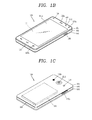
- FIGS. 1B and 1C are conceptual views of one example of the mobile terminal, viewed from different directions.
- the mobile terminal 100 is shown having components such as a wireless communication unit 110, an input unit 120, a sensing unit 140, an output unit 150, an interface unit 160, a memory 170, a controller 180, and a power supply unit 190. It is understood that implementing all of the illustrated components is not a requirement, and that greater or fewer components may alternatively be implemented.
- the mobile terminal 100 is shown having wireless communication unit 110 configured with several commonly implemented components.
- the wireless communication unit 110 typically includes one or more components which permit wireless communication between the mobile terminal 100 and a wireless communication system or network within which the mobile terminal is located.
- the wireless communication unit 110 typically includes one or more modules which permit communications such as wireless communications between the mobile terminal 100 and a wireless communication system, communications between the mobile terminal 100 and another mobile terminal, communications between the mobile terminal 100 and an external server. Further, the wireless communication unit 110 typically includes one or more modules which connect the mobile terminal 100 to one or more networks. To facilitate such communications, the wireless communication unit 110 includes one or more of a broadcast receiving module 111, a mobile communication module 112, a wireless Internet module 113, a short-range communication module 114, and a location information module 115.
- the input unit 120 includes a camera 121 for obtaining images or video, a microphone 122, which is one type of audio input device for inputting an audio signal, and a user input unit 123 (for example, a touch key, a push key, a mechanical key, a soft key, and the like) for allowing a user to input information.
- Data for example, audio, video, image, and the like
- controller 180 may analyze and process data (for example, audio, video, image, and the like) according to device parameters, user commands, and combinations thereof.
- the sensing unit 140 is typically implemented using one or more sensors configured to sense internal information of the mobile terminal, the surrounding environment of the mobile terminal, user information, and the like.
- the sensing unit 140 is shown having a proximity sensor 141 and an illumination sensor 142.
- the sensing unit 140 may alternatively or additionally include other types of sensors or devices, such as a touch sensor, an acceleration sensor, a magnetic sensor, a G-sensor, a gyroscope sensor, a motion sensor, an RGB sensor, an infrared (IR) sensor, a finger scan sensor, a ultrasonic sensor, an optical sensor (for example, camera 121), a microphone 122, a battery gauge, an environment sensor (for example, a barometer, a hygrometer, a thermometer, a radiation detection sensor, a thermal sensor, and a gas sensor, among others), and a chemical sensor (for example, an electronic nose, a health care sensor, a biometric sensor, and the like), to name a few.
- the mobile terminal 100 may be configured to utilize information obtained from sensing unit 140, and in particular, information obtained from one or more sensors of the sensing unit 140, and combinations thereof.
- the output unit 150 is typically configured to output various types of information, such as audio, video, tactile output, and the like.
- the output unit 150 is shown having a display unit 151, an audio output module 152, a haptic module 153, and an optical output module 154.
- the display unit 151 may have an inter-layered structure or an integrated structure with a touch sensor in order to facilitate a touch screen.
- the touch screen may provide an output interface between the mobile terminal 100 and a user, as well as function as the user input unit 123 which provides an input interface between the mobile terminal 100 and the user.
- the interface unit 160 serves as an interface with various types of external devices that can be coupled to the mobile terminal 100.
- the interface unit 160 may include any of wired or wireless ports, external power supply ports, wired or wireless data ports, memory card ports, ports for connecting a device having an identification module, audio input/output (I/O) ports, video I/O ports, earphone ports, and the like.
- the mobile terminal 100 may perform assorted control functions associated with a connected external device, in response to the external device being connected to the interface unit 160.
- the memory 170 is typically implemented to store data to support various functions or features of the mobile terminal 100.
- the memory 170 may be configured to store application programs executed in the mobile terminal 100, data or instructions for operations of the mobile terminal 100, and the like. Some of these application programs may be downloaded from an external server via wireless communication. Other application programs may be installed within the mobile terminal 100 at time of manufacturing or shipping, which is typically the case for basic functions of the mobile terminal 100 (for example, receiving a call, placing a call, receiving a message, sending a message, and the like). It is common for application programs to be stored in the memory 170, installed in the mobile terminal 100, and executed by the controller 180 to perform an operation (or function) for the mobile terminal 100.
- the controller 180 typically functions to control overall operation of the mobile terminal 100, in addition to the operations associated with the application programs.
- the controller 180 may provide or process information or functions appropriate for a user by processing signals, data, information and the like, which are input or output by the various components depicted in Fig. 1A , or activating application programs stored in the memory 170.
- the controller 180 controls some or all of the components illustrated in FIGS. 1A-1C according to the execution of an application program that have been stored in the memory 170.
- the power supply unit 190 can be configured to receive external power or provide internal power in order to supply appropriate power required for operating elements and components included in the mobile terminal 100.
- the power supply unit 190 may include a battery, and the battery may be configured to be embedded in the terminal body, or configured to be detachable from the terminal body.
- CDMA Code Division Multiple Access
- present invention may be also applicable to all communication systems including a CDMA wireless communication system.
- a CDMA wireless communication system may include a plurality of terminals 100, a plurality of base stations (BSs) 270, a plurality of base station controllers (BSCs) 275, and a mobile switching center (MSC) 280.
- the MSC 280 may interface with a Public Switched Telephone Network (PSTN) 290, and the MSC 280 may also interface with the BSCs 275.
- PSTN Public Switched Telephone Network
- the BSCs 275 may be connected to the BSs 270 via backhaul lines.
- the backhaul lines may be configured in accordance with at least any one of E1/T1, ATM, IP, PPP, Frame Relay, HDSL, ADSL, or xDSL, for example.
- the system illustrated in FIG. 2A may include a plurality of BSCs 275.
- Each of the plurality of BSs 270 may include at least one sector, each sector having an omni-directional antenna or an antenna indicating a particular radial direction from the base station 270. Alternatively, each sector may include two or more antennas with various forms. Each of the BSs 270 may be configured to support a plurality of frequency assignments, each frequency assignment having a particular spectrum (for example, 1.25 MHz, 5 MHz, etc.).
- the intersection of a sector and frequency assignment may be referred to as a CDMA channel.
- the BSs 270 may also be referred to as Base Station Transceiver Subsystems (BTSs).
- BTSs Base Station Transceiver Subsystems
- the term "base station” may collectively refer to a BSC 275, and at least one BS 270.
- the base stations may also indicate "cell sites". Alternatively, individual sectors for a specific BS 270 may also be referred to as a plurality of cell sites.
- the Broadcasting Transmitter (BT) 295 may transmit broadcasting signals to the mobile terminals 100 being operated within the system.
- the broadcast receiving module 111 as illustrated in FIG. 1 may be provided in the mobile terminal 100 to receive broadcast signals transmitted by the BT 295.
- FIG. 2A illustrates several global positioning system (GPS) satellites 300.
- GPS global positioning system
- Such satellites 300 facilitate locating at least one of a plurality of mobile terminals 100. Though two satellites are illustrated in FIG. 2A , location information may be obtained with a greater or fewer number of satellites.
- the location information module 115 as illustrated in FIG. 1 may cooperate with the satellites 300 as illustrated in FIG. 2A to obtain desired location information.
- other types of position detection technology all types of technologies capable of tracing the location may be used in addition to a GPS location technology.
- at least one of the GPS satellites 300 may alternatively or additionally provide satellite DMB transmissions.
- the BS 270 may receive reverse-link signals from various mobile terminals 100. At this time, he mobile terminals 100 may perform calls, message transmissions and receptions, and other communication operations. Each reverse-link signal received by a specific base station 270 may be processed within that specific base station 270. The processed resultant data may be transmitted to an associated BSC 275.
- the BSC 275 may provide call resource allocation and mobility management functions including the systemization of soft handoffs between the base stations 270.
- the BSCs 275 may also transmit the received data to the MSC 280, which provides additional transmission services for interfacing with the PSTN 290.
- the PSTN 290 may interface with the MSC 280
- the MSC 280 may interface with the BSCs 275.
- the BSCs 275 may also control the BSs 270 to transmit forward-link signals to the mobile terminals 100.
- WiFi Wireless Fidelity positioning system
- the WiFi positioning system (WPS) 300 refers to a location determination technology based on a wireless local area network (WLAN) using WiFi as a technology for tracking the location of the mobile terminal 100 using a WiFi module provided in the mobile terminal 100 and a wireless access point 520 for transmitting and receiving to and from the WiFi module.
- WLAN wireless local area network
- the WiFi positioning system 300 may include a WiFi location determination server 510, a mobile terminal 100, a wireless access point (AP) 520 connected to the mobile terminal 100, and a database 530 stored with any wireless AP information.
- the WiFi location determination server 510 extracts the information of the wireless AP 520 connected to the mobile terminal 100 based on a location information request message (or signal) of the mobile terminal 100.
- the information of the wireless AP 520 may be transmitted to the WiFi location determination server 510 through the mobile terminal 100 or transmitted to the WiFi location determination server 510 from the wireless AP 520.
- the information of the wireless AP extracted based on the location information request message of the mobile terminal 100 may be at least one of MAC address, SSID, RSSI, channel information, privacy, network type, signal strength and noise strength.
- the WiFi location determination server 510 receives the information of the wireless AP 520 connected to the mobile terminal 100 as described above, and compares the received wireless AP 520 information with information contained in the pre-established database 530 to extract (or analyze) the location information of the mobile terminal 100.
- the wireless AP connected to the mobile terminal 100 is illustrated as a first, a second, and a third wireless AP 520.
- the number of wireless APs connected to the mobile terminal 100 may be changed in various ways according to a wireless communication environment in which the mobile terminal 100 is located.
- the WiFi positioning system 300 can track the location of the mobile terminal 100.
- the information of any wireless APs stored in the database 530 may be information such as MAC address, SSID, RSSI, channel information, privacy, network type, latitude and longitude coordinate, building at which the wireless AP is located, floor number, detailed indoor location information (GPS coordinate available), AP owner's address, phone number, and the like.
- any wireless AP information and location information corresponding to the any wireless AP are stored together in the database 530, and thus the WiFi location determination server 510 may retrieve wireless AP information corresponding to the information of the wireless AP 520 connected to the mobile terminal 100 from the database 530 to extract the location information matched to the searched wireless AP, thereby extracting the location information of the mobile terminal 100.
- FIGS. 2a and 2b are conceptual views of a communication system operable with a mobile terminal in accordance with the present disclosure.
- such communication systems utilize different air interfaces and/or physical layers.
- air interfaces utilized by the communication systems include Frequency Division Multiple Access (FDMA), Time Division Multiple Access (TDMA), Code Division Multiple Access (CDMA), and Universal Mobile Telecommunications System (UMTS), the Long Term Evolution (LTE) of the UMTS, the Global System for Mobile Communications (GSM), and the like.
- FDMA Frequency Division Multiple Access
- TDMA Time Division Multiple Access
- CDMA Code Division Multiple Access
- UMTS Universal Mobile Telecommunications System
- LTE Long Term Evolution
- GSM Global System for Mobile Communications
- a CDMA wireless communication system having a plurality of mobile terminals 100, a plurality of base stations (BSs) 270, base station controllers (BSCs) 275, and a mobile switching center (MSC) 280.
- the MSC 280 is configured to interface with a conventional Public Switch Telephone Network (PSTN) 290.
- PSTN Public Switch Telephone Network
- the MSC 280 is also configured to interface with the BSCs 275.
- the BSCs 275 are coupled to the base stations 270 via backhaul lines.
- the backhaul lines may be configured in accordance with any of several known interfaces including, for example, E1/T1, ATM, IP, PPP, Frame Relay, HDSL, ADSL, or xDSL.
- the plurality of BSCs 275 can be included in the system as shown in FIG. 2A .
- Each base station 270 may include one or more sectors, each sector having an omni-directional antenna or an antenna pointed in a particular direction radially away from the base station 270. Alternatively, each sector may include two or more different antennas. Each base station 270 may be configured to support a plurality of frequency assignments, with each frequency assignment having a particular spectrum (e.g., 1.25 MHz, 5 MHz, etc.).
- the intersection of sector and frequency assignment may be referred to as a CDMA channel.
- the base stations 270 may also be referred to as Base Station Transceiver Subsystems (BTSs).
- BTSs Base Station Transceiver Subsystems
- the term "base station” may be used to refer collectively to a BSC 275, and one or more base stations 270.
- the base stations may also be denoted as "cell sites.” Alternatively, individual sectors of a given base station 270 may be referred to as cell sites.
- a broadcasting transmitter (BT) 295 transmits a broadcast signal to the mobile terminals 100 operating within the system.
- the broadcast receiving module 111 ( FIG. 1 ) is typically configured inside the mobile terminal 100 to receive broadcast signals transmitted by the BT 295.
- FIG. 2a further depicts several Global Positioning System (GPS) satellites 300.
- GPS Global Positioning System
- Such satellites 300 facilitate locating the position of at least one of plural mobile terminals 100.
- Two satellites are depicted in FIG. 2a , but it is understood that useful position information may be obtained with greater or fewer satellites than two satellites.
- the GPS module 115 FIG. 1 ) is typically configured to cooperate with the satellites 300 to obtain desired position information. It is to be appreciated that other types of position detection technology, (i.e., location technology that may be used in addition to or instead of GPS location technology) may alternatively be implemented. If desired, at least one of the GPS satellites 300 may alternatively or additionally be configured to provide satellite DMB transmissions.
- the base stations 270 receive sets of reverse-link signals from various mobile terminals 100.
- the mobile terminals 100 are engaging in calls, messaging, and executing other communications.
- Each reverse-link signal received by a given base station 270 is processed within that base station 270.
- the resulting data is forwarded to an associated BSC 275.
- the BSC 275 provides call resource allocation and mobility management functionality including the orchestration of soft handoffs between base stations 270.
- the BSCs 275 also route the received data to the MSC 280, which then provides additional routing services for interfacing with the PSTN 290.
- the PSTN 290 interfaces with the MSC 280
- the MSC 280 interfaces with the BSCs 275, which in turn control the base stations 270 to transmit sets of forward-link signals to the mobile terminals 100.
- the WiFi positioning system (WPS) 300 refers to a location determination technology based on a wireless local area network (WLAN) using WiFi as a technology for tracking the location of the mobile terminal 100 using a WiFi module provided in the mobile terminal 100 and a wireless access point 320 for transmitting and receiving to and from the WiFi module.
- WLAN wireless local area network
- the WiFi positioning system 300 may include a WiFi location determination server 310, a mobile terminal 100, a wireless access point (AP) 320 connected to the mobile terminal 100, and a database 330 stored with any wireless AP information.
- the WiFi location determination server 310 extracts the information of the wireless AP 320 connected to the mobile terminal 100 based on a location information request message (or signal) of the mobile terminal 100.
- the information of the wireless AP 320 may be transmitted to the WiFi location determination server 310 through the mobile terminal 100 or transmitted to the WiFi location determination server 310 from the wireless AP 320.
- the information of the wireless AP extracted based on the location information request message of the mobile terminal 100 may be at least one of MAC address, SSID, RSSI, channel information, privacy, network type, signal strength and noise strength.
- the WiFi location determination server 310 receives the information of the wireless AP 320 connected to the mobile terminal 100 as described above, and compares the received wireless AP 320 information with information contained in the pre-established database 330 to extract (or analyze) the location information of the mobile terminal 100.
- the wireless AP connected to the mobile terminal 100 is illustrated as a first, a second, and a third wireless AP 320.
- the number of wireless APs connected to the mobile terminal 100 may be changed in various ways according to a wireless communication environment in which the mobile terminal 100 is located.
- the WiFi positioning system 300 can track the location of the mobile terminal 100.
- the information of any wireless APs stored in the database 330 may be information such as MAC address, SSID, RSSI, channel information, privacy, network type, latitude and longitude coordinate, building at which the wireless AP is located, floor number, detailed indoor location information (GPS coordinate available), AP owner's address, phone number, and the like.
- any wireless AP information and location information corresponding to the any wireless AP are stored together in the database 330, and thus the WiFi location determination server 310 may retrieve wireless AP information corresponding to the information of the wireless AP 320 connected to the mobile terminal 100 from the database 330 to extract the location information matched to the searched wireless AP, thereby extracting the location information of the mobile terminal 100.
- the extracted location information of the mobile terminal 100 may be transmitted to the mobile terminal 100 through the WiFi location determination server 310, thereby acquiring the location information of the mobile terminal 100.
- FIG. 3A is a front perspective view illustrating another example of a mobile terminal associated with the present disclosure
- FIG. 3B is a rear perspective view of a mobile terminal illustrated in FIG. 3A .
- a mobile terminal 200 disclosed herein has a portable phone body in a bar shape.
- the present disclosure may not be necessarily limited to this, and may be also applicable to various structures of terminals such as a slide type, a folder type, a swing type, a swivel type, and the like, in which two and more bodies are combined with each other in a relatively movable manner.
- the body includes a case (casing, housing, cover, etc.) forming an appearance of the terminal.
- the case may be divided into a front case 201 and a rear case 202.
- Various electronic components may be incorporated in a space formed between the front case 201 and the rear case 202.
- At least one middle case may be additionally disposed between the front case 201 and the rear case 202.
- the cases may be formed by injection-molding a synthetic resin or may be also formed of a metal material such as stainless steel (STS), titanium (Ti), or the like.
- STS stainless steel
- Ti titanium
- a display unit 251, an audio output module 252, a camera module 221, and the like may be disposed on the terminal body, mainly on the front case 201.
- the display unit 251 occupies most of a main surface of the front case 101.
- the display unit is disposed on a front surface of the terminal, and formed to display visual information.
- the display unit 251 according to the present disclosure may be formed on a front surface of the terminal as well as in a form extended to another surface of the terminal. More specifically, the display unit 251 may include a first region 261 disposed on the front surface, and a second region 262, 263 extended from the first region 261 and disposed on a lateral surface of the body.
- the lateral surface may be a surface which is seen by the user when a mobile terminal is seen from the lateral surface (or side).
- the second region 262, 263 may be disposed on a front surface thereof.
- the second region 262, 263 may be formed over a lateral surface and a front surface of the terminal.
- whether or not the second region 262, 263 is seen from the front surface is determined according to a structure in which the first and the second region 261, 262, 263 are formed on the display unit 251.
- a window disposed on an upper surface of the display unit 251 is formed in a shape in which both lateral surfaces are bent down, and through this, the appearance of a front surface and a lateral surface of the body is formed by the window.
- the first region 261 and second region 262, 263 may be connected to each other in a shape having no physical interface.
- the display unit 251 is formed in a bent shape, and may include display elements integrated to correspond to the window.
- the display unit 251 may be a flexible display unit.
- the flexible display may include a flexible, bendable, twistable, foldable and rollable display.
- the flexible display unit may include both typical flexible displays and electronic paper.
- typical flexible display may be a light and non-fragile rigid display fabricated on a thin and flexible substrate that can be warped, bent, folded or rolled like a paper sheet while maintaining the display characteristics of a flat display in the related art.
- electronic paper as a display technology to which a typical characteristic of ink is applied may be different from that of a typical flat panel display in which reflective light is used.
- Electronic paper may change a drawing or text using twist balls or electrophoresis using capsules.
- a form in which a flexible display unit is extended to a front surface and both lateral surfaces thereof has been described in the above, but the present disclosure may be also configured with a form in which three independent display units are disposed on a front surface and both lateral surfaces thereof.
- a front display unit 261 and a lateral display unit 262, 263 are independent display units, respectively, and may be configured with a form in which they are disposed in an adjacent manner.
- the audio output unit 252 and a camera module 221 may be disposed in a region adjacent to one of both end portions of the display unit 251, and a front input unit (not shown) and a microphone 222 may be disposed in a region adjacent to the other end portion.
- the front input unit as an example of the user input unit 230 may include a plurality of manipulating units.
- the manipulating units may be commonly referred to as a manipulating portion, and any method may be employed if it is a tactile manner allowing the user to perform manipulation with a tactile feeling.
- the display unit 251 may form a touch screen along with a touch sensor, and in this case, the touch screen may be a user input unit.
- the touch screen may be a user input unit.
- a mobile terminal may be configured to enable input manipulation to the terminal body only through the display unit 251 and a rear input unit 232 which will be described later.
- a camera module 221' may be additionally mounted on a rear surface of the terminal body, namely, the rear case 202.
- the camera module 221' has an image capturing direction, which is substantially opposite to the direction of the camera 221 (refer to FIG. 3A ), and may have a different number of pixels from that of the camera module.
- the camera module 221 has a relatively small number of pixels enough not to cause a difficulty when the user captures his or her own face and immediately sends it to the other party during a video call or the like, and the camera module 221' has a relatively large number of pixels since the user often captures a general object but does not sends it immediately.
- the camera modules 221, 221' may be provided in the terminal body in a rotatable and popupable manner.
- a flash and a mirror may be additionally disposed adjacent to the camera module 221'.
- the flash illuminates light toward an subject when capturing the subject with the camera module 221'.
- the mirror allows the user to look at his or her own face, or the like, in a reflected way when capturing himself or herself (in a self-portrait mode) by using the camera module 221'.
- An audio output unit may be additionally disposed on a rear surface of the terminal body.
- the audio output unit on a rear surface thereof together with the audio output unit 252 (refer to FIG. 3A ) on a front surface thereof can implement a stereo function, and may be also used to implement a speaker phone mode during a phone call.
- a second audio output unit configured with a speaker on a rear surface of the terminal may be formed along with the audio output unit 252 (first audio output unit) configured with a receiver on a front surface thereof.
- a power supply unit 290 for supplying power to the portable terminal 200 may be mounted on the terminal body.
- the power supply unit 290 may be configured to be incorporated in the terminal body, or directly detachable from the outside of the terminal body.
- a rear input unit 232 may be disposed on a rear surface of the terminal body.
- the rear input unit 232 may be located at a lower portion of the camera module 221', for example.
- the rear input unit 232 may be manipulated to receive a command for controlling the operation of the mobile terminal 200, and the received content may be set in various ways. For example, it may be possible to receive a command such as power on/off, start, end, scroll or the like, or a command such as volume adjustment output from the audio output unit 252, switching to a touch recognition mode of the display unit 251, or the like. However, the present disclosure may not be necessarily limited to this, and the terminal may include only either one or both of the front input unit and rear input unit 232.
- the controller 180 may control the function of the terminal using a display unit disposed on a lateral surface of the terminal.
- the second region 262 denotes a display region disposed at a left side of both lateral surfaces based on the front surface
- the third region 263 denotes a display region disposed at a right side of both lateral surfaces based on the front surface
- the first region 261 denotes a display (front display) disposed on the front surface.
- the display unit 251 may further include a lateral display unit only at either one of the left and the right sides thereof based on the first region 261.
- the display unit 251 including display regions (or display units) at a front surface, a left and a right sides thereof, respectively, will be described as an example.
- a front display unit (or first region) will be described using reference numeral “261 or 151a”, and a lateral display unit (or second region) will be described using reference numeral “151b", “262” or “263”. And, the lateral display unit is also called “touch sensing unit”. Moreover, the content that can be applicable to both the front and lateral display unit will be described as a “display unit 251 or 151” instead of reference numerals indicating the front and lateral display units, regardless of distinguishing the front and lateral display unit.
- FIG. 4 is a flow chart for explaining a control method according to an embodiment of the present disclosure
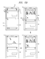
- FIG. 5A is a conceptual view for explaining the control method of FIG. 4 .
- the display unit 151a displays first screen information 510.
- the first screen information 510 may correspond to an execution screen of an activated application.
- the first screen information 510 may correspond to an execution screen of a message application.
- the mobile terminal 100 may execute a plurality of applications, and activate one of the plurality of applications.
- the controller may control the display unit to display visual information on the application being executed by a preset control command.
- the controller may control the display unit to sequentially display visual information in the activated sequence of the corresponding applications based on the control command.
- the touch sensing unit 151b is formed adjacent to both lateral surfaces of the display unit 151 along a length direction of the display unit 151.
- the user may apply a touch input to the touch sensing unit 151b formed by interposing the display unit 151 therebetween with his or her two fingers.
- the touch sensing unit 151b may be configured with a display device for displaying visual data, and may be formed to be incorporated with the display unit 151 as described above. Accordingly, preset visual information may be displayed on the touch sensing unit 151b configured with the display device. For example, the controller may control the touch sensing unit 151b to illuminate one region of the touch sensing unit 151b to which the user's touch is applied.
- a consecutive touch input is applied to the touch sensing unit 151b (S502).
- the touch inputs may be preferably applied to the both touch sensing units 151b at the same time, but may not be necessarily limited to this.
- the consecutive touch input is an input scheme due to a finger moving along a length direction of the display unit.
- the touch range of the consecutive touch inputs is defined according to a length to which the touch input is applied as well as a location to which an initial touch is applied.
- the controller controls the display unit 151 to display second screen information in one region of the display unit corresponding to the touch range of consecutive touch inputs (S503).
- the second screen information may correspond to an execution screen of another application.
- the controller controls the display unit 151 to switch part of first screen information which is the execution screen of the first application to second screen information which is an execution screen of a second application.
- the second application may correspond to an execution screen of a gallery application for displaying a plurality of images.
- the display unit displays the second screen information 520 in a partial region of the display unit corresponding to a touch distance based on a touch range corresponding to the touch distance applied to the touch sensing unit 151b.
- the partial region corresponds to a region corresponding to a distance from an initial touch applied to the touch sensing unit 151b to a final movement position.
- Touch inputs applied to the both touch sensing units 151b may preferably move in substantially parallel to each other, but may not be necessarily limited to this.
- the display unit displays the second screen information 520 in a region corresponding to the touch range, and displays part of the first screen information 510 in the remaining region.
- the second screen information 520 corresponds to part of an execution screen of the second application.
- the controller activates the first and the second application at the same time, and controls the display unit to display part of the execution screen of the first and the second application in each divided region of the display unit.
- the second application corresponds to an application being executed along with the first application but in an inactive state. Furthermore, the second application corresponds to an application activated immediately prior to or subsequent to activating the first application.
- the touch sensing unit 151b senses a touch input applied in both directions, namely, applied along a length direction or an opposite direction thereof of the display unit. For example, when a touch input consecutively applied from the top to the bottom, the controller may control the display unit to activate an application immediately prior to activating a currently activated application, and display an execution screen thereof.
- the controller controls the display unit to display one region of each screen information along a direction in which the touch input is applied. For example, when the touch input moves in a downward direction based on the display unit, the display unit display an upper region of the first screen information 510 at a lower end portion of the display unit, and a lower region of the second screen information 520 at an upper end portion of the display unit.
- the controller controls the display unit to limit the output of part of the first screen information and display second screen information in a larger region in real time as increasing the touch range from a moment at which an initial touch is applied to the touch sensing unit 151b.
- the controller controls the display unit to display the second screen information 520 as a whole on the display unit. For example, when the touch input is consecutively applied from the uppermost end to the lowermost end of a lateral surface of the display unit, the controller controls the display unit to switch from the first screen information 510 to the second screen information 520. Furthermore, the controller may control the display unit to increase a region displayed with the second screen information 520 as decreasing a region displayed with the first screen information 510.
- the controller may switch the first application to an inactive state.
- the touch sensing unit 151b senses a touch input applied in an opposite direction. In other words, when a touch input moving from the lowermost end of the touch sensing unit 151b to the uppermost end thereof by the touch sensing unit 151b, the controller controls the display unit to switch the second screen information 520 to the first screen information 510 again.
- the controller controls the display unit to display the execution screen of a previous application again based on the touch input applied in an opposite direction.
- the controller may sequentially record applications activated by the user, and sequentially display the execution screens of the applications based on the direction of a consecutive touch input applied to the touch sensing unit 151b. It is assumed that a first through a third application care being executed, and a first application through a third application have been sequentially activated, and an execution screen of the second application is currently being displayed on the display unit.
- the controller may control the display unit to display an execution screen of the first application based on a touch input applied to the touch sensing unit 151b in a downward direction, and display an execution screen of the third application based on a touch input applied to the touch sensing unit 151b in an upward direction.
- the user may immediately execute an application that has been previously executed regardless of entering an additional control command to check information on an application currently being executed again.
- a control method of each application in a state that first and second screen information are displayed will be described with reference to 5B.
- the controller displays the first screen information 510 in one region of the display unit based on a consecutive touch input applied to the touch sensing unit 151b, and displays the second screen information 520 in the remaining region.
- the controller may apply a touch input to the second screen information 520 to control the second application.
- the second application corresponds to a gallery application for displaying images stored in the memory 160
- the second screen information 520 includes a plurality of images in a reduced size.
- the controller controls the display unit to display only the image in an enlarged size.
- the controller controls the display unit to display at least part 520' of the image in the remaining region of the display unit.
- the display unit controls the second application based on a touch input applied to the second screen information 520, and displays a changed execution screen of the second application in the remaining region.
- the first application may be controlled by a touch input applied to the first screen information 510.
- the controller may activate the first and the second application at the same time while the first and the second screen information 510, 520 are displayed at the same time.
- the user may activate the first and the second application at the same time, and receive the resultant execution screens at the same time.
- a control method of providing an icon of a recommended application based on a touch input applied to the touch sensing unit 151b will be described with reference to FIG. 5C .
- the controller controls the display unit to display an execution screen of an application that has been just previously activated based on a touch input applied to the touch sensing unit 151b in a downward direction, and display an execution screen of an application that has been just subsequently (more recently) activated based on a touch input applied to the touch sensing unit 151b in an upward direction.
- the controller when a touch input is applied to the touch sensing unit 151b in an upward direction, the controller display an execution screen of an application that has been recently activated rather than the current application. However, when the first application of the first screen information 510 is a most recently activated application, the controller provides information on a recommended application.
- the controller controls the display unit to display recommended icons corresponding to at least one application at a lower end portion of the display unit.
- the recommended application may be previously set by the user, or recommended as a result of analyzing the first screen information 510.
- the recommended icon may include a first icon 531 previously set by the user.
- the first icon 531 may correspond to a graphic image for receiving a touch input to switch the screen to a home screen page.
- the recommended icon may include a second icon 532 for an application expected to be used through the analysis of the first screen information 510 and a third icon 533 for an application associated with information contained in the first screen information 510.
- the first screen information 510 may include text such as "Show me a photo" in the message.
- the controller may expect that the user executes a gallery application to share images, and display a second icon 532 of the gallery application.
- the controller may control the display unit to display a third icon 533 of the phone application.
- the controller analyzes the execution trend of each application using the recorded execution history of a user. For example, the controller may recommend an application having a high frequency of being executed along the message application. For example, when a user frequently executes an Internet connection application while activating the message application, the display unit may display a fourth icon 534 of the Internet connection application.
- the recommended icons are displayed to occupy a preset region of the display unit. Referring to FIG. 5C(b) , the recommended icons are displayed to cover part of the first screen information 510.
- the display unit may display the recommended icons to limit the display of an upper end portion of the first screen information 510 and connect to a lower end portion of the first screen information 510 by moving the first screen information 510.
- the display unit may move the first screen information 510 in an upward direction and display the icons in the remaining region thereof.
- the location of displaying the icons may not be necessarily limited to this.
- the controller may control the display unit to display the recommended icons at an upper portion of the display unit.
- the user may execute his or her desired application in a more convenient manner using the recommended application.
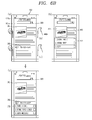
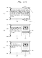
- FIG. 5D(a) when the consecutive touch input is suspended in one region of the touch sensing unit 151 b, the controller displays part of the first and the second screen information 510, 520 at the same time on the display unit.
- a boundary between the first and the second screen information 510, 520 corresponds to the location of the touch sensing unit 151b to which the user's touch input is applied.
- the controller controls the display unit to display only one of the first and the second screen information 510, 520.
- the controller selects screen information displayed in the largest region of the display unit. Accordingly, the controller controls such that the display of the first screen information 510 is limited, and the second screen information 520 is displayed as a whole on the display unit.
- the controller may control the display unit to display the first and the second screen information 510, 520 at the same time.
- the controller may control the display unit to display the first and the second screen information 510, 520 at the same time.
- the display region and boundary of the first and the second screen information 510, 520 may correspond to one region of a touch sensing unit to which the long touch input is applied.
- the user may receive at least one desired screen information in a more convenient manner.
- FIGS. 6A and 6B are conceptual views for explaining a control method of displaying additional information on one content selected from a plurality of contents contained in screen information.
- FIG. 6A(a) illustrates a display unit for displaying a first execution screen 540 of a gallery application in which a plurality of images acquired through different views of angle or schemes are displayed at the same time.
- the controller senses one region of the touch sensing unit 151b to which the touch input is applied.
- the first execution screen 540 contains a plurality of contents, and the contents correspond to a plurality of images.
- the controller selects at least one content displayed in one region of the display unit corresponding to one region of the touch sensing unit 151b on which the touch input is sensed.
- one region of the display unit corresponding to one region of the touch sensing unit 151b is determined by two touch input positions applied in parallel to both touch sensing units 151b formed at the both lateral surface thereof. Defining a virtual line connecting two touch input positions applied to the both touch sensing units 151b, the virtual line passes one region of the display unit based on a touch input consecutively applied along one direction.
- the controller selects content displayed in one region of the display unit through which the virtual line passes. In other words, the controller controls the display unit to display content displayed in a row on the display unit corresponding to the touch range.
- the controller controls the display unit to display first additional information 550 associated with the selected content.
- the first additional information 550 may be preferably displayed in a region adjacent to the selected content.
- the controller may control the display unit to display in such a manner that the first additional information 550 covers one region of the first execution screen 540.
- a region of the display unit displayed with the first additional information 550 may not be necessarily limited to this.
- the controller may control the display unit to move part of the first execution screen 540 to another region to secure a region in which the first additional information 550 is to be displayed.
- the first additional information 550 may correspond to a menu for controlling (or editing) the selected content.
- the first additional information 550 may correspond to a menu image for receiving a touch input to hide, edit or arrange the contents.
- the controller may select a plurality of contents displayed in one row since the plurality of contents are selected by a touch input in a row unit.
- the controller may select only one content from the plurality of contents using a touch input applied to the display unit. For example, as illustrated in the drawing, three images are selected based on a touch input applied to the touch sensing unit 151b, and the display unit displays a menu image for the three images. Consequently, the controller selects one image based on a touch input applied to the display unit, and controls the selected one image based on an additional touch input applied to the menu image.
- the controller controls the display unit to cover or (limit the display of) the selected one content 541 based on a user's plurality of touch inputs.
- the controller may control the display unit to limit the display of the first additional information 550 based on a touch input applied along a direction opposite to the touch sensing unit 151b.
- the controller controls the display unit to select content using a touch input applied along the one direction and display the first additional information 550 according to the selected content, and controls the display unit to allow the displayed first additional information 550 to disappear by a touch input applied along an opposite direction.
- a consecutive touch input applied along the opposite direction may be defined as a touch input applied in such a manner that the virtual line passes through the first additional information 550.
- the controller may control the display unit limit the display of the first additional information 550 and the selected one content 541 based on a touch input applied to the touch sensing unit 151 b.
- all contents contained in a row through which the virtual line passes may be selected based on the touch input.
- the controller may select the plurality of rows, and perform editing on the text.
- the user may select at least one content displayed on the display unit using a touch input to one region of the touch sensing unit, and more easily receive additional information thereon.
- a control method of providing distinguished additional information on selected content will be described with reference to FIG. 6B .
- FIG. 6B(a) is a view illustrating a display unit displaying the execution screen 560 corresponding to a web browser screen.
- the execution screen 560 includes different forms of contents.
- the execution screen 560 may include an image, an input window, text, video, an image connected to a hyperlink, an icon and the like.
- the execution screen 560 may include first content 561 containing an image and text and second content 562 with a numeric form.
- the controller selects the first content 561 based on a touch input applied to the touch sensing unit 151 b.
- a method of selecting the content is substantially the same as the method of f6A, and thus the redundant description thereof will be omitted.
- the controller may control the display unit to select the first content 561 based on the touch input, and display the second additional information 571 in a region adjacent to the execution screen 560.
- the second additional information 571 corresponds to information associated with the first content 561.
- the second additional information 571 may correspond to a menu image configured to receive a touch input for storing the image, storing the text or copying the image and text.
- the controller selects the second content 562 based on the touch input.
- the controller controls the display unit to display third additional information 572 associated with the second content 562 in a region adjacent to the 562 the second content 562.
- the third additional information 572 may include a menu image for placing a call using the number, storing a numeral as a phone number or receiving a touch input to transmit text.
- the controller activates an application based on a touch input applied to one region of the menu image and performs a selected function using information contained in the content.
- the user may select one of a plurality of contents, and receive additional information associated with the selected content.
- FIGS. 7A through 7C are conceptual views for explaining a control method of displaying lower information of the selected content.
- FIG. 7A(a) is a view illustrating a display unit for displaying the first execution screen 540 containing a plurality of image groups. Though not shown in the drawing, the controller may display at least one lower image contained in the image group on the display unit based on a touch input applied to the image group.
- the controller selects at least one image group displayed in a row of the image group contained in the first execution screen 540 based on a touch input applied to the touch sensing unit 151b.
- the controller may control the display unit to display at least one image contained in the selected image group based on the touch input consecutively applied to the touch sensing unit 151b.
- the controller may preferably control the display unit to display first lower information 551 of the selected image group, and display the first lower information 551 in a region adjacent to the selected image group 541.
- the controller may control the display unit to display the first lower information 551 in one region of the display unit through which a line defined by a consecutive touch input applied to the touch sensing unit 151b passes. Furthermore, the display unit may display a larger number of the first lower information 551 as increasing a region of the applied touch input.
- the controller controls the display unit to display the larger amount of images as increasing the touch range.
- the user may check a plurality of images contained in the image group without applying a touch input to an image group displayed on the display unit. Furthermore, when a plurality of image groups are selected, the user may receive distinguished images contained in each image group at the same time.
- the controller controls the display unit to display the second lower information 552 of the selected image group.
- the second lower information 552 may correspond to the generation information, setting information, size or the like of the image group.
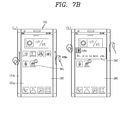
- a control method of providing third lower information contained in an application without activating the application in a home screen page will be described with reference to FIG. 7B .
- FIG. 7B(a) is a view illustrating a display unit for displaying third screen information 580 corresponding to a home screen page.
- the third screen information 580 may include at least one icon for receiving a touch input to execute at least one application.
- the display unit may further display a notification badge on the icon when an event occurs or is received at the application. For example, when a message is received at the mobile terminal, the display unit may further display a notification badge on the icon 581 of the message application.
- the controller may select at least one of the plurality of icons based on a touch input applied to the touch sensing unit 151b when the home screen page is displayed.
- the controller may control the display unit to display additional information on an application corresponding to the selected icon. For example, the controller selects at least one icon displayed in one region of the display unit corresponding to a touch range of the touch sensing unit 151 b.
- the controller may display third lower information 590 on the application of an icon formed with the notification badge among the selected icons.
- the controller may control the display unit to display the received message.
- the controller may control the display unit to display the additional information of an application corresponding to the selected icon when there is no event or notification corresponding to the selected icon.
- the additional information may correspond to the description of the application, information associated with setting, used memory or the like.
- the display unit may display the third lower information 590 in one region of the display unit corresponding to the touch range based on the touch range.
- the user may receive information on an event on a home screen page without activating an application containing the received event.
- the controller may control the display unit to limit the display of the third lower information 590 when a touch input in an opposite direction is applied to the touch sensing unit 151b or a touch input is applied to one region of the display unit (a region in which the third lower information 590 is not displayed).
- the controller may control the display unit to activate the application, and display an execution screen of the application.
- the touch sensing unit 151b may be implemented as a display device for displaying visual information. Accordingly, if necessary, the controller may control the touch sensing unit 151b to display an image.
- the present embodiment may not be necessarily limited to the control method illustrated in the drawing, and may be applicable to all the foregoing embodiments.
- the controller controls such that the notification image 600 is displayed in one region of the touch sensing unit 151b.
- the notification image 600 may be formed with a preset image or form of emitting light.
- the notification image 600 may be preferably formed in a region adjacent to content containing additional information or lower information.
- the controller controls the touch sensing unit 151b to display a notification image 600 in a row displayed with the image 542.
- the controller controls the display unit to display the image 542 in an enlarged manner and display the lower information 553 at the same time by a touch input applied to the image 542.
- the controller controls the display unit to display the lower information 553.
- the controller may control the touch sensing unit 151b to move the display location of the notification image 600 based on a consecutive touch input applied to the touch sensing unit 151b.
- the present disclosure may not be necessarily limited to this, and the touch sensing unit 151b may modify the shape of the notification image 600 or fix the location of the notification image 600 based on the touch input.
- the notification image 600 may be displayed at an upper portion or lower portion of the touch sensing unit 151 b.
- the user may apply a touch input to the touch sensing unit 151 b to check whether or not there is receivable information or content associated with receivable information in advance.
- FIG. 8 is a conceptual view for explaining a control method according to a touch scheme of a touch input applied to touch sensing units at both sides thereof.
- FIG. 8A is a view illustrating a display unit for display the first screen information of the first application.
- the controller may control the display unit based on a consecutive touch input applied to the touch sensing unit 151b on one lateral surface thereof in a state that touch inputs are applied to the touch sensing units on both lateral surfaces thereof at the same time.
- the second screen information 520 of the second application is displayed along with the first screen information 510.
- a region of the display unit on which the second screen information 520 is displayed is based on the touch range of a touch input applied to the right touch sensing unit 151b. In other words, even in case of a consecutive touch input being applied only to one side of the touch sensing unit as well as consecutive touch inputs being applied to the left and right side thereof at the same time, it may be possible to activate another application.
- the controller controls the display unit to display the first and the second screen information 510, 520 using one region of the left touch sensing unit 151b to which the long touch input is applied as a boundary.
- the display information of the screen information cannot be controlled by the touch range of a consecutive touch input to the right touch sensing unit 151 b.
- FIG. 9 is a flow chart illustrating a method of controlling both lateral surface of the display unit according to the present disclosure
- FIGS. 10A , 10B , 10C and 10D are conceptual views illustrating the control method of FIG. 9 .
- a mobile terminal may perform the process of displaying screen information in a first region disposed on a front surface of the body (S910).
- a mobile terminal may further include a display unit 251 on which a first region 261 is disposed on a front surface of the body, and a second region 262, 263 connected to the first region and disposed on a lateral surface of the body.
- Screen information associated with a function that can be driven in the mobile terminal may be displayed on the display unit 251.
- the screen information may be the execution screen information of an application installed in the mobile terminal.
- a graphic object such as an icon, a widget or the like indicating an application installed in the mobile terminal may be displayed on the display unit 251.
- screen information associated with a function that can be driven in the mobile terminal may be displayed even in a second region as well as in the first region 261.
- a mobile terminal may sense a preset type of touch being applied to a second region disposed on a lateral surface of the body (S920).
- the controller 180 may control the first and the second region in an interlocking manner.
- the controller 180 may control screen information displayed in the first region using a touch applied to the second region.
- controlling screen information may be understood as performing a function associated with the screen information.
- the controller 180 may perform the function of scrolling the web page according to a drag input applied to the second region 262 in a state that screen information indicating a web page is displayed in the second region 262.
- a mobile terminal may further include a sensing unit 140 capable of sensing a touch applied to the first and the second region.
- the sensing unit 140 may be a touch sensor configured to sense a touch applied to the display unit 251.
- a display unit disposed on a lateral surface of the body may include a second region 262 disposed on a left lateral surface thereof and a third region 263 disposed on a right lateral surface thereof.
- the controller 180 may sense a touch applied to at least part of the second and the third region using the sensing unit 140.
- the controller 180 may determine whether or not a preset type of touch has been sensed in the second and the third region.
- the preset type of touch may use various touch input schemes such as a drag input, a multi touch or the like applied to at least part of the second and the third region.
- the controller 180 may sense a drag input applied to the second and the third region at the same time.
- the direction of the drag input may be the same direction or different directions in the second and the third region.
- a mobile terminal may perform the process of displaying information associated with screen information displayed in the first region in a direction different from the displayed direction of the screen information (S930).
- a mobile terminal may display screen information having at least two or more display directions in the first region.
- the user may view at least two screen information having different directions at the same time.
- the controller 180 may display screen information having a second display direction which is different from the first display direction in at least part of the first region.
- the display direction of the screen information may denote a direction in which the screen information is displayed on the display unit 251. More specifically, the display direction of the screen information may be determined according to the posture of the mobile terminal body. For example, when the display direction of the screen information displayed in a posture in which a front surface of the display unit 251 is placed in a horizontal direction is defined as a first display direction, the display direction of the screen information displayed in a posture in which a front surface of the display unit 251 is placed in a vertical direction may be defined as a second display direction. In other words, the second display direction may be displayed with a difference of 90 degrees from the first display direction.
- the screen information having different directions may denote screen information displayed according to the posture of the body.
- screen information 1010 having a first display direction may denote screen information displayed when the body is placed in a horizontal direction
- screen information 1020 having a second display direction may be understood as screen information displayed when the body is place in a vertical direction.
- the display direction of the screen information may be determined by a preset type of touch.
- the display direction of the screen information may be determined according to the direction of a drag input applied to the second region.
- the second display direction may be determined by a direction in which a preset touch is applied.
- the controller 180 may determine a direction corresponding to the direction of a drag input applied to the second region as a second display direction.
- screen information having the first display direction and screen information having the second display direction may be screen information associated with each other.
- screen information having the first display direction is screen information indicating the outgoing and incoming record of SMS text messages
- screen information having the second display direction may be screen information indicating a list of recipients capable of transmitting an SMS text messages.
- screen information having the second display direction may be screen information to be displayed in the first region when screen information having the first display direction is displayed in the second display direction. More specifically, screen information displayed in the first region may be displayed any one of the first display direction and second display direction. In this case, in a state that screen information having the first display direction is displayed in the first region, the controller 180 may display the same information in the second display direction at the same time.
- screen information having the first display direction and screen information having the second display direction are screen information unrelated to each other.
- screen information having the first display direction is screen information associated with the execution of a first application installed in the mobile terminal
- screen information having the second display direction may be screen information associated with the execution of a second application which is different from the first application.
- the second application may be any one of a plurality of applications being currently executed in the mobile terminal which is different from the first application.
- screen information having various display directions such as a third and a fourth display direction may be displayed at the same time.
- a case where two screen information having two directions are displayed at the same time will be described, but it may be also applicable to a case where a plurality of screen information having a plurality of display directions are displayed.
- the controller 180 may display screen information having the second display direction in at least part of the screen information having the first display direction.
- the controller 180 may display screen information having the second display direction in a region corresponding to a region in which a preset type of touch is sensed.
- screen information having the first display direction may maintain the display state as it is.
- screen information having the second display direction may be displayed to be overlapped with screen information having the first display direction.
- a region displayed with screen information having the second display direction may be determined based on a region in which the preset type of touch is sensed in the first region. For example, when the preset type of touch is a drag input applied to the second and the third region 262, 263 at the same time, screen information having the second display direction may be displayed in a region having a length corresponding to a length over which the drag input is sensed.
- the controller 180 may switch screen information having the first display direction into screen information having the second display direction.
- the user may switch the display direction of the screen information with no posture change of the display unit 251.
- the posture of the display unit 251 may be either one of a posture in which the display unit 251 is placed in a vertical direction and a posture in which the display unit 251 is placed in a horizontal direction.
- an indicator indicating the relevance may be displayed on at least one of the screen information having the first and the second display direction.
- the controller 180 may display the same portion to be visually distinguished from the remaining screen information.
- the controller 180 may process a region indicating the same information as the screen information having the first display direction in the screen information having the second display direction in highlighted manner to visually distinguish it from the remaining screen information.
- the controller 180 may control the other screen information in response to a touch manipulation with respect to either one of the screen information having the first and the second direction.
- the control of the screen information may denote performing various functions associated with screen information such as scrolling screen information, switching screen information or the like.
- a mobile terminal may include a display unit 251 having a first region 261 and a second region 262, 263.
- an execution screen associated with an application being executed in the mobile terminal may be displayed in the first region 261.
- the execution screen may be screen information 1010 associated with map information.
- the screen information 1010 as well as map information may have a first display direction.
- the controller 180 may sense a touch applied to the second region 262, 263. More specifically, when the second region is divided into a first sub-region 262 and a second sub-region 263, the controller may sense a touch applied to at least one of the first and the second sub-region 262, 263. For example, as illustrated in FIG. 10A(b) , the controller 180 may sense a drag input applied to the first and the second sub-region 262, 263 at the same time.
- the controller 180 may display information having a second display direction which is different from the first display direction in at least part of the first region. For example, as illustrated in FIG. 10A(c) , the controller 180 may display screen information in the form of being displayed when information displayed in the first display direction has a second display direction which is different from the first display direction in at least part of the first region. More specifically, when screen information having the first display direction is screen information on which map information is displayed in a horizontal direction based on the front surface of the display unit 251, screen information having the second display direction may be screen information 1020 on which the map information is displayed in a vertical direction based on the front surface of the display unit 251.
- the user may receive screen information having various display directions with no posture change or additional manipulation of the mobile terminal body.
- the controller 180 may determine a region displayed with screen information having the second display direction based on a region in which a preset touch is sensed. For example, as illustrated in FIG. 10B(b) , the controller 180 may sense a drag input in the second region 262, 263. Here, the controller 180 may determine a region in which screen information having the second display direction is displayed based on a length over which the drag input is sensed in the second region 262, 263 within the first region 261.
- the controller 180 may display screen information having the second display direction in a region having a length corresponding to a length over which the drag input is sensed in the second region 262, 263 within the first region 261.
- the user may adjust the length of a drag input applied to the second region to determine the size of a region in which screen information having a different display direction is to be displayed.
- the controller 180 may display screen information 1020 having the second display direction in a region corresponding to a region to which a drag input is applied. More specifically, the controller 180 may detect the start position and end position of a drag input applied to the second region 262, 263. For example, as illustrated in FIG. 10C(b) , the controller 180 may detect a region from a position corresponding to the start position of the drag input to a position corresponding to the end position thereof within the first region.
- the controller 180 may display screen information 1020 having the second display direction in the detected region.
- the user may determine a region in which screen information having the second display direction is to be displayed.
- controller 180 may no longer display screen information having the second display direction in response to a preset touch being sensed in a state that screen information having the first and the second display direction are displayed at the same time in the first region 261.
- the controller 180 may allow screen information 1020 having the second display direction to disappear from the first region.
- the screen information 1010 having the first display direction may be displayed in the first region 261.
- FIGS. 11A and 11B are conceptual views for explaining a relationship between screen information associated with each other.
- a mobile terminal may display screen information having a first and a second display direction at the same time.
- the screen information having the first and the second display direction may be screen information associated with each other.
- the first screen information is a screen information indicating part of a document
- the second screen information may be screen information indicating another part of the document containing the document content of the first screen information.
- the screen information having the first and the second display direction may be screen information on which part of the same document has a different display direction.
- the controller 180 may visually display a relationship with the relevant screen information. More specifically, the controller 180 may display screen information having the first and the second display direction in such a manner that a region displayed with the same information is distinguished from another region.
- the controller 180 may display screen information 1120 having a second display direction which is different from the first display direction in at least part of the first region.
- the controller 180 may detect a region in which the same information is displayed in the screen information having the first display direction and screen information having the second display direction. For example, when screen information having the first display direction is information indicating part of a document, the controller 180 may detect a region displayed with the same information as information indicating the screen information having the first display direction in the screen information having the second display direction.
- the controller 180 may display a region displayed with the same information to be visually distinguished from another region in at least one of the screen information having the first and the second display direction.
- the controller 180 may process either one of the screen information having the first and the second display direction in a visually distinguished manner, and process both the screen information having the first and the second display direction in a visually distinguished manner.
- the controller 180 may select the screen information in a visually distinguished manner based on a preset condition.
- the preset condition may be a condition containing a larger amount of screen information between the screen information having the first and the second display direction.
- containing a larger amount of screen information may denote that either one thereof contains all the screen information displayed in the other one thereof.
- the controller 180 may process a region 1130 displayed with the same information as the screen information 1110 having the first display direction within the screen information 1120 having the second display direction in a highlighted manner.
- the highlight processing may be expressed using the contrast, color, graphic object or the like of the region.
- the controller 180 may process a region displayed with the same information as the screen information having the second display direction within the screen information having the first display direction in a highlighted manner. For example, as illustrated in FIG. 11 B(b), when screen information having a first display direction is displayed on screen information having a second display direction, the controller 180 may process a region 430 displayed with the same information within the screen information 1120 having the second display direction in a highlighted manner.
- the controller 180 may detect screen information having a larger amount of screen information while containing a region displayed with the same information within screen information having a first and a second display direction, and process the region displayed with the same information within the detected screen information in a highlighted manner.
- the controller 180 may control another one using a touch to either one of the screen information having the first and the second display region. For example, as illustrated in FIG. 11 C(b), a region 1130 currently corresponding to the first display region may be processed in a highlighted manner in the second display region.
- the controller 180 may sense a touch being applied to any one region within a region displayed with screen information 1120 having a second display direction.
- the controller 180 may scroll screen information having the first display direction such that information displayed in a region displayed with a position at which the touch is sensed is displayed on screen information having the first display direction.
- the region 1130 corresponding to a region in which the touch is sensed may be processed in a highlighted manner.
- FIGS. 12A and 12B are conceptual views for explaining an embodiment of displaying screen information having a second display direction.
- the controller 180 may display screen information having a display direction which is different from the display direction of the screen information displayed in the first region in at least part of screen information displayed in the first region based on a preset touch being applied thereto.
- the preset type of touch as a touch applied to the display unit 251 may be determined by at least one of a region in which the touch is applied, a time for which the touch is applied, a method with which the touch is applied, an area in which the touch is applied, and a length over which the touch is applied.
- the preset type of touch may be a drag input applied to the second region 262, 263 at the same time. Furthermore, the preset type of touch may be also determined by the direction of the drag input.
- the preset type of touch may be a touch sensed in a region having an area larger than a preset area applied to either one of the first and the second sub-region 262, 263.
- the preset type of touch may be touches applied to the first and the second sub-region at the same time.
- the directions of the touches applied to the first and the second sub-region may have the same or different directions.
- touches applied to the first and the second sub-region may be applied in different directions.
- the controller 180 may display the screen information having different directions in at least part of the first region 261.
- screen information having different display directions have been displayed by a touch applied to the second region 262, 263.
- the user may view at least two screen information according to at least two directions at once with a simple manipulation.
- the present disclosure may not be necessarily limited to this, and may display screen information having different directions by various control commands.
- various schemes may be used such as a preset type of touch applied to the first region, a button input, a voice input, and the like.
- FIGS. 13A and 13B are conceptual views illustrating a method of determining at least one of at least some of the display locations of screen information having the first and the second display direction.
- the controller 180 may change at least one of the display locations of the screen information having the first and the second display direction based on a preset type of touch applied to the second region 262, 263 in a state that the screen information having the first display direction and screen information having the second display direction are displayed in the first region at the same time.
- the controller 180 may sense touches applied to the second region 262, 263 at the same time in different directions. In this case, as illustrated in FIG. 13A(b) , the controller 180 may change a location at which the screen information 1010 having the first display direction is displayed and a location at which the screen information 1020 having the second display direction is displayed in response to the touch. In other words, the user may view the display locations of the screen information 1010 having the first display direction and screen information 1020 having the second display direction, which are displayed in a changed manner.
- the controller 180 may change the display location of the screen information 1020 having the second display direction while not changing the display location of the screen information 1010 having the first display direction.
- the controller 180 may rotate and display the screen information 1020 having the second display direction according to the extent of drag inputs applied to the second region 262, 263 in different directions.
- the screen information 1020 having the second display direction may be displayed to be overlapped with the screen information 1010 having the first display direction.
- FIGS. 14A , 14B , 14C and 14D are conceptual views illustrating a type of screen information having a second display direction.
- the controller 180 may display screen information having a second display direction to be overlapped with at least part of the first region.
- the screen information having the second display direction may have been previously set or may be set by the user. More specifically, the screen information having the second display direction may previously correspond to the screen information having the first display direction, respectively. Furthermore, the user may directly set the screen information having the second display direction for each of the screen information having the first display direction.
- the screen information having the second display direction may be screen information associated with the screen information having the first display direction.
- the screen information having the first display direction may be screen information 1400a associated with the transmission and reception of messages.
- the screen information having the second display direction may be screen information 1400b indicating an identification information list of external terminals capable of transmitting and receiving messages.
- the screen information having the first display direction may be screen information 1410a associated with schedule management.
- the screen information having the second display direction may be screen information 1410b screen information indicating a to-do list associated with the schedule.
- the screen information having the first display direction may be any one image 1420a among a plurality of images stored in the memory unit 170 of the mobile terminal.
- the screen information having the second display direction may be screen information 1420b indicating at least some of a plurality of images stored in the memory unit 170 of the mobile terminal.
- the screen information having the first display direction may be any one slide 1430a among PPT slides.
- the screen information having the second display direction may be screen information 1430b indicating the PPT list.
- the screen information having the second display direction as information associated with the screen information having the first display direction may be screen information providing the user that being displayed in a second display direction is more convenient than being displayed in a first display direction.
- FIGS. 15A and 15B are conceptual views illustrating a method of displaying images received from cameras having different capture directions.
- a mobile terminal may further include a camera unit 121.
- the camera unit 121 may be configured to change its capture direction.
- the present disclosure may include at least two camera units 121a, 121b having different capture directions.
- the term of camera unit 121 may be used as a term including all of at least two camera units 121a, 121b having different capture directions.
- the controller 180 may display an image 1510 received from the camera unit 121a.
- the controller 180 may activate the camera unit 121b in which the received image 1510 has a different capture direction from the capture direction.
- the controller 180 may display an image 1520 received from the camera unit 121b having the different capture direction to be overlapped with at least part of the received image 1510.
- the controller 180 may display images received from the camera units 121a, 121b having different capture direction at the same time.
- a preset type of touch may be a touch applied to the second region 262, 263.
- the camera units 121a, 121b having different capture directions can be used, the present disclosure may be configured to receive images captured by the rotation of the camera unit 121.
- the controller 180 may display an image 810 received through either one camera unit 121a between the camera units 121a, 121b having opposite capture directions to each other. At this time, when a preset type of touch is sensed, the controller 180 may display images received from the any one camera unit 121a and the other camera unit 121b in at least part 1530 of the displayed image 1510.
- an image received from the camera unit 121b having the different capture direction may be applicable to all the foregoing embodiments of screen information having a second display direction.
- FIG. 16 is a conceptual view illustrating that a specific region of the screen information having a first display direction is set to screen information having a second display direction.
- the controller 180 may change at least some of the display directions of the screen information having the first display direction.
- the screen information changed in the display direction may be displayed to be overlapped with the screen information having the first display direction.
- the screen information changed in the display direction may be screen information determined that being displayed to have a second display direction among screen information having the first display direction is more convenient.
- the screen information having the first display direction is document information
- the screen information having the second display direction may be an image contained in the document information.
- a drag input may be sensed in the second region 262, 263 in a state that document information 1610 is displayed in the first region 261.
- the controller 180 may determine the content of the document information 1610, and detect object information to be displayed in a second display direction which is different from the first display direction.
- the object information may be an image 920.
- the controller 180 may display the detected image 1620 in at least part of the document information 1610.
- the user may view screen information on which the display direction is changed only in at least part thereof, thereby providing screen information with a higher readability.
- the direction of screen information displayed on the display unit may be implemented with only a simple manipulation, thereby providing images having various display directions to the user.
- the display direction of screen information displayed on the display unit may be changed through a manipulation to a lateral surface of the display unit, thereby providing a screen with a higher readability to the user.
- the foregoing present invention may be implemented as codes readable by a computer on a medium written by the program.
- the computer-readable media may include all kinds of recording devices in which data readable by a computer system is stored. Examples of the computer-readable media may include hard disk drive (HDD), solid state disk (SSD), ROM, RAM, CD-ROM, magnetic tape, floppy disk, and optical data storage device, and the like, and also include a device implemented in the form of a carrier wave (for example, transmission via the Internet).
- the computer may include the controller 180 of the terminal.
Landscapes
- Engineering & Computer Science (AREA)
- Theoretical Computer Science (AREA)
- General Engineering & Computer Science (AREA)
- Human Computer Interaction (AREA)
- Physics & Mathematics (AREA)
- General Physics & Mathematics (AREA)
- Software Systems (AREA)
- User Interface Of Digital Computer (AREA)
- Telephone Function (AREA)
Applications Claiming Priority (2)
| Application Number | Priority Date | Filing Date | Title |
|---|---|---|---|
| KR1020130139290A KR102106873B1 (ko) | 2013-11-15 | 2013-11-15 | 이동 단말기 및 이의 제어 방법 |
| KR1020140069547A KR102135374B1 (ko) | 2014-06-09 | 2014-06-09 | 이동 단말기 및 이의 제어 방법 |
Publications (2)
| Publication Number | Publication Date |
|---|---|
| EP2874053A2 true EP2874053A2 (de) | 2015-05-20 |
| EP2874053A3 EP2874053A3 (de) | 2015-07-22 |
Family
ID=51999221
Family Applications (1)
| Application Number | Title | Priority Date | Filing Date |
|---|---|---|---|
| EP14192840.8A Withdrawn EP2874053A3 (de) | 2013-11-15 | 2014-11-12 | Mobiles Endgerät und Verfahren zur Steuerung davon |
Country Status (3)
| Country | Link |
|---|---|
| US (1) | US9990125B2 (de) |
| EP (1) | EP2874053A3 (de) |
| CN (1) | CN104657051A (de) |
Cited By (4)
| Publication number | Priority date | Publication date | Assignee | Title |
|---|---|---|---|---|
| CN106293444A (zh) * | 2015-06-25 | 2017-01-04 | 小米科技有限责任公司 | 移动终端、显示控制方法及装置 |
| EP3133484A1 (de) * | 2015-08-17 | 2017-02-22 | Lg Electronics Inc. | Mobiles endgerät und steuerungsverfahren dafür |
| EP3343341A4 (de) * | 2015-11-17 | 2018-09-12 | Samsung Electronics Co., Ltd. | Berührungseingabeverfahren durch edge-screen und elektronische vorrichtung |
| WO2020147665A1 (zh) * | 2019-01-15 | 2020-07-23 | Oppo广东移动通信有限公司 | 文件处理方法、装置、终端及存储介质 |
Families Citing this family (36)
| Publication number | Priority date | Publication date | Assignee | Title |
|---|---|---|---|---|
| KR101515623B1 (ko) * | 2012-05-14 | 2015-04-28 | 삼성전자주식회사 | 벤디드 디스플레이를 갖는 휴대단말의 기능 운용 방법 및 장치 |
| USD753667S1 (en) * | 2012-12-14 | 2016-04-12 | Lg Electronics Inc. | Television receiver with graphical user interface |
| AU349920S (en) * | 2013-01-05 | 2013-07-29 | Samsung Electronics Co Ltd | Display screen for an electronic device |
| AU350078S (en) * | 2013-01-09 | 2013-08-02 | Samsung Electronics Co Ltd | Display screen for an electronic device |
| USD742894S1 (en) * | 2013-06-10 | 2015-11-10 | Apple Inc. | Display screen or portion thereof with graphical user interface |
| USD739873S1 (en) * | 2013-06-10 | 2015-09-29 | Huawei Technologies Co., Ltd. | Display screen with icon |
| USD763280S1 (en) * | 2013-07-10 | 2016-08-09 | Samsung Electronics Co., Ltd. | Display screen or portion thereof with graphical user interface |
| WO2015050345A1 (en) * | 2013-10-01 | 2015-04-09 | Lg Electronics Inc. | Control apparatus for mobile terminal and control method thereof |
| USD752078S1 (en) * | 2013-10-03 | 2016-03-22 | Thales Avionics, Inc. | Display screen or portion thereof with graphical user interface |
| USD740844S1 (en) * | 2013-11-15 | 2015-10-13 | Tencent Technology (Shenzhen) Company Limited | Display screen or portion thereof with graphical user interface |
| USD751117S1 (en) | 2014-02-07 | 2016-03-08 | Apple Inc. | Display screen or portion thereof with animated graphical user interface |
| KR102295844B1 (ko) * | 2014-11-18 | 2021-08-31 | 삼성전자 주식회사 | 전자장치에서 화면의 표시를 제어하는 장치 및 방법 |
| KR20160098752A (ko) * | 2015-02-11 | 2016-08-19 | 삼성전자주식회사 | 디스플레이 장치 및 디스플레이 방법 및 컴퓨터 판독가능 기록매체 |
| KR102378570B1 (ko) | 2015-06-08 | 2022-03-25 | 삼성전자주식회사 | 휴대 장치 및 휴대 장치의 화면 변경방법 |
| KR101719208B1 (ko) * | 2015-06-17 | 2017-03-23 | 주식회사 하이딥 | 디스플레이 모듈을 포함하는 압력 검출 가능한 터치 입력 장치 |
| CN109901765B (zh) * | 2015-10-06 | 2022-06-21 | 佳能株式会社 | 电子设备及其控制方法 |
| JP7041409B2 (ja) * | 2015-10-27 | 2022-03-24 | ディセントラライズド モバイル アプリケーションズ エルティーディー | 安全なトランザクションインターフェース |
| CN105278752B (zh) * | 2015-10-30 | 2018-08-14 | 努比亚技术有限公司 | 一种触摸操作装置及方法 |
| KR102427833B1 (ko) * | 2015-11-30 | 2022-08-02 | 삼성전자주식회사 | 사용자 단말장치 및 디스플레이 방법 |
| KR20170077670A (ko) * | 2015-12-28 | 2017-07-06 | 삼성전자주식회사 | 컨텐츠를 제어하기 위한 방법 및 그 전자 장치 |
| US20170317960A1 (en) * | 2016-04-28 | 2017-11-02 | Jamdeo Canada Ltd. | Device and methods for messaging application control and presentation |
| CN113687758B (zh) * | 2016-06-07 | 2024-04-12 | 北京三星通信技术研究有限公司 | 基于辅助显示区域的操作方法及终端设备 |
| USD803238S1 (en) | 2016-06-12 | 2017-11-21 | Apple Inc. | Display screen or portion thereof with graphical user interface |
| KR102760797B1 (ko) | 2017-01-04 | 2025-02-03 | 삼성전자주식회사 | 전자 장치 및 전자 장치의 어플리케이션 실행 히스토리 표시 방법 |
| US11574715B2 (en) | 2017-05-17 | 2023-02-07 | Blue Storm Media Inc | System and method for a health status display |
| KR102421518B1 (ko) * | 2017-06-27 | 2022-07-15 | 엘지전자 주식회사 | 전자장치 및 이의 제어방법 |
| USD859444S1 (en) * | 2017-12-22 | 2019-09-10 | Facebook, Inc. | Display panel of a programmed computer system with a graphical user interface |
| USD865785S1 (en) * | 2017-12-28 | 2019-11-05 | Facebook, Inc. | Display panel of a programmed computer system with a graphical user interface |
| US10955956B2 (en) * | 2018-05-07 | 2021-03-23 | Apple Inc. | Devices, methods, and graphical user interfaces for interaction with an intensity-sensitive input region |
| USD901525S1 (en) | 2018-09-11 | 2020-11-10 | Apple Inc. | Electronic device with animated graphical user interface |
| US11797113B2 (en) | 2019-06-01 | 2023-10-24 | Apple Inc. | Devices, methods, and graphical user interfaces for interaction with a control |
| USD1036452S1 (en) * | 2020-07-31 | 2024-07-23 | Canva Pty Ltd | Display screen or portion thereof with graphical user interface |
| USD996461S1 (en) * | 2021-05-18 | 2023-08-22 | Eoflow Co., Ltd. | Display screen or portion thereof with transitional graphical user interface |
| CN115407952A (zh) * | 2021-05-28 | 2022-11-29 | 上海擎感智能科技有限公司 | 一种应用图标的显示方法及装置 |
| US11907516B2 (en) * | 2022-04-16 | 2024-02-20 | Samsung Electronics Co., Ltd. | Electronic device, method, and non-transitory computer readable storage medium for identifying set of information according to change in size of display area of flexible display |
| US12327014B2 (en) | 2023-03-03 | 2025-06-10 | Apple Inc. | Devices, methods, and user interfaces for edge and corner interactions |
Citations (1)
| Publication number | Priority date | Publication date | Assignee | Title |
|---|---|---|---|---|
| US20130002524A1 (en) * | 2010-10-01 | 2013-01-03 | Z124 | Smart pad operation with differing aspect ratios |
Family Cites Families (18)
| Publication number | Priority date | Publication date | Assignee | Title |
|---|---|---|---|---|
| US7800592B2 (en) | 2005-03-04 | 2010-09-21 | Apple Inc. | Hand held electronic device with multiple touch sensing devices |
| US7782363B2 (en) * | 2000-06-27 | 2010-08-24 | Front Row Technologies, Llc | Providing multiple video perspectives of activities through a data network to a remote multimedia server for selective display by remote viewing audiences |
| US20090113296A1 (en) * | 2007-10-26 | 2009-04-30 | Microsoft Corporation | Displaying a map and associated symbolic context information |
| EP2351362A1 (de) * | 2008-09-22 | 2011-08-03 | International Business Machines Corporation | Verfahren und system zum wiedergeben von video auf einem mobilgerät |
| EP3907593B1 (de) * | 2010-01-19 | 2025-03-26 | LG Electronics, Inc. | Mobiles endgerät und steuerungsverfahren dafür |
| US8842080B2 (en) * | 2010-10-01 | 2014-09-23 | Z124 | User interface with screen spanning icon morphing |
| WO2012068551A1 (en) * | 2010-11-18 | 2012-05-24 | Google Inc. | Surfacing off-screen visible objects |
| JP5714935B2 (ja) | 2011-02-24 | 2015-05-07 | 京セラ株式会社 | 携帯電子機器、接触操作制御方法および接触操作制御プログラム |
| JP5806822B2 (ja) | 2011-02-24 | 2015-11-10 | 京セラ株式会社 | 携帯電子機器、接触操作制御方法および接触操作制御プログラム |
| JP2012174247A (ja) | 2011-02-24 | 2012-09-10 | Kyocera Corp | 携帯電子機器、接触操作制御方法および接触操作制御プログラム |
| BR112014002039B1 (pt) * | 2011-08-05 | 2022-02-01 | Interdigital Ce Patent Holdings | Interface de usuário para um exibidor de vídeo, e método para controlar um exibidor de vídeo que tem uma tela ativável por toque |
| JP5766083B2 (ja) | 2011-09-28 | 2015-08-19 | 京セラ株式会社 | 携帯電子機器 |
| KR20130054071A (ko) | 2011-11-16 | 2013-05-24 | 삼성전자주식회사 | 다중 어플리케이션을 실행하는 모바일 장치 및 그 방법 |
| US9032292B2 (en) * | 2012-01-19 | 2015-05-12 | Blackberry Limited | Simultaneous display of multiple maximized applications on touch screen electronic devices |
| US10078420B2 (en) * | 2012-03-16 | 2018-09-18 | Nokia Technologies Oy | Electronic devices, associated apparatus and methods |
| CN102915176A (zh) * | 2012-09-19 | 2013-02-06 | 东莞宇龙通信科技有限公司 | 一种分屏显示的方法和装置 |
| US9658740B2 (en) * | 2013-03-15 | 2017-05-23 | Apple Inc. | Device, method, and graphical user interface for managing concurrently open software applications |
| KR101584590B1 (ko) * | 2013-07-11 | 2016-01-13 | 삼성전자주식회사 | 어플리케이션을 표시하는 사용자 단말 장치 및 그 방법 |
-
2014
- 2014-11-04 US US14/532,825 patent/US9990125B2/en active Active
- 2014-11-12 EP EP14192840.8A patent/EP2874053A3/de not_active Withdrawn
- 2014-11-13 CN CN201410640323.7A patent/CN104657051A/zh active Pending
Patent Citations (1)
| Publication number | Priority date | Publication date | Assignee | Title |
|---|---|---|---|---|
| US20130002524A1 (en) * | 2010-10-01 | 2013-01-03 | Z124 | Smart pad operation with differing aspect ratios |
Cited By (12)
| Publication number | Priority date | Publication date | Assignee | Title |
|---|---|---|---|---|
| CN106293444A (zh) * | 2015-06-25 | 2017-01-04 | 小米科技有限责任公司 | 移动终端、显示控制方法及装置 |
| EP3109727A3 (de) * | 2015-06-25 | 2017-03-22 | Xiaomi Inc. | Verfahren und vorrichtung zur steuerung einer anzeige und mobiles endgerät |
| JP2017522841A (ja) * | 2015-06-25 | 2017-08-10 | シャオミ・インコーポレイテッド | 移動端末、表示制御方法及び装置、プログラム及び記録媒体 |
| RU2643564C2 (ru) * | 2015-06-25 | 2018-02-02 | Сяоми Инк. | Способ и устройство для управления отображением, а также мобильный терминал |
| US10620825B2 (en) | 2015-06-25 | 2020-04-14 | Xiaomi Inc. | Method and apparatus for controlling display and mobile terminal |
| US11226736B2 (en) | 2015-06-25 | 2022-01-18 | Xiaomi Inc. | Method and apparatus for controlling display and mobile terminal |
| EP3133484A1 (de) * | 2015-08-17 | 2017-02-22 | Lg Electronics Inc. | Mobiles endgerät und steuerungsverfahren dafür |
| US9983722B2 (en) | 2015-08-17 | 2018-05-29 | Lg Electronics Inc. | Mobile terminal and control method thereof |
| EP3343341A4 (de) * | 2015-11-17 | 2018-09-12 | Samsung Electronics Co., Ltd. | Berührungseingabeverfahren durch edge-screen und elektronische vorrichtung |
| US11003328B2 (en) | 2015-11-17 | 2021-05-11 | Samsung Electronics Co., Ltd. | Touch input method through edge screen, and electronic device |
| WO2020147665A1 (zh) * | 2019-01-15 | 2020-07-23 | Oppo广东移动通信有限公司 | 文件处理方法、装置、终端及存储介质 |
| US11347389B2 (en) | 2019-01-15 | 2022-05-31 | Guangdong Oppo Mobile Telecommunications Corp., Ltd. | File processing method, terminal, and storage medium |
Also Published As
| Publication number | Publication date |
|---|---|
| US20150143238A1 (en) | 2015-05-21 |
| EP2874053A3 (de) | 2015-07-22 |
| CN104657051A (zh) | 2015-05-27 |
| US9990125B2 (en) | 2018-06-05 |
Similar Documents
| Publication | Publication Date | Title |
|---|---|---|
| EP2874053A2 (de) | Mobiles Endgerät und Verfahren zur Steuerung davon | |
| US11150742B2 (en) | Deformable display device and operating method thereof | |
| US10203863B2 (en) | Flexible display device and operating method thereof | |
| US10379720B2 (en) | Flexible display device and operating method thereof | |
| US9953617B2 (en) | Flexible display device and operating method thereof | |
| EP3098802B1 (de) | Flexible anzeigevorrichtung und betriebsverfahren dafür | |
| US10007475B2 (en) | Flexible display device | |
| US9609225B2 (en) | Deformable display device and operating method thereof | |
| US20170091340A1 (en) | Display device and operating method thereof | |
| US20200076940A1 (en) | Mobile terminal and flexible display device | |
| US10509561B2 (en) | Transformable display and method for operating same | |
| US12425510B2 (en) | Mobile terminal | |
| EP3547100A2 (de) | Mobiles endgerät und verfahren zum betrieb davon | |
| CN105577913B (zh) | 移动终端及其控制方法 | |
| US10491742B2 (en) | Mobile terminal and control method thereof | |
| KR20160074329A (ko) | 이동 단말기 및 그의 동작 방법 |
Legal Events
| Date | Code | Title | Description |
|---|---|---|---|
| PUAI | Public reference made under article 153(3) epc to a published international application that has entered the european phase |
Free format text: ORIGINAL CODE: 0009012 |
|
| 17P | Request for examination filed |
Effective date: 20141112 |
|
| AK | Designated contracting states |
Kind code of ref document: A2 Designated state(s): AL AT BE BG CH CY CZ DE DK EE ES FI FR GB GR HR HU IE IS IT LI LT LU LV MC MK MT NL NO PL PT RO RS SE SI SK SM TR |
|
| AX | Request for extension of the european patent |
Extension state: BA ME |
|
| PUAL | Search report despatched |
Free format text: ORIGINAL CODE: 0009013 |
|
| AK | Designated contracting states |
Kind code of ref document: A3 Designated state(s): AL AT BE BG CH CY CZ DE DK EE ES FI FR GB GR HR HU IE IS IT LI LT LU LV MC MK MT NL NO PL PT RO RS SE SI SK SM TR |
|
| AX | Request for extension of the european patent |
Extension state: BA ME |
|
| RIC1 | Information provided on ipc code assigned before grant |
Ipc: G06F 3/0354 20130101ALI20150616BHEP Ipc: G06F 3/0481 20130101AFI20150616BHEP Ipc: G06F 3/0488 20130101ALI20150616BHEP |
|
| R17P | Request for examination filed (corrected) |
Effective date: 20160118 |
|
| RBV | Designated contracting states (corrected) |
Designated state(s): AL AT BE BG CH CY CZ DE DK EE ES FI FR GB GR HR HU IE IS IT LI LT LU LV MC MK MT NL NO PL PT RO RS SE SI SK SM TR |
|
| 17Q | First examination report despatched |
Effective date: 20160601 |
|
| STAA | Information on the status of an ep patent application or granted ep patent |
Free format text: STATUS: EXAMINATION IS IN PROGRESS |
|
| STAA | Information on the status of an ep patent application or granted ep patent |
Free format text: STATUS: THE APPLICATION IS DEEMED TO BE WITHDRAWN |
|
| 18D | Application deemed to be withdrawn |
Effective date: 20180308 |