EP2874065A2 - Procédé et appareil pour commander des systèmes de commande d'aéronef - Google Patents
Procédé et appareil pour commander des systèmes de commande d'aéronef Download PDFInfo
- Publication number
- EP2874065A2 EP2874065A2 EP14193335.8A EP14193335A EP2874065A2 EP 2874065 A2 EP2874065 A2 EP 2874065A2 EP 14193335 A EP14193335 A EP 14193335A EP 2874065 A2 EP2874065 A2 EP 2874065A2
- Authority
- EP
- European Patent Office
- Prior art keywords
- inputs
- output
- input
- truth table
- control system
- Prior art date
- Legal status (The legal status is an assumption and is not a legal conclusion. Google has not performed a legal analysis and makes no representation as to the accuracy of the status listed.)
- Granted
Links
Images


Classifications
-
- G—PHYSICS
- G06—COMPUTING OR CALCULATING; COUNTING
- G06F—ELECTRIC DIGITAL DATA PROCESSING
- G06F11/00—Error detection; Error correction; Monitoring
- G06F11/36—Prevention of errors by analysis, debugging or testing of software
- G06F11/3668—Testing of software
- G06F11/3672—Test management
- G06F11/3676—Test management for coverage analysis
-
- G—PHYSICS
- G05—CONTROLLING; REGULATING
- G05B—CONTROL OR REGULATING SYSTEMS IN GENERAL; FUNCTIONAL ELEMENTS OF SUCH SYSTEMS; MONITORING OR TESTING ARRANGEMENTS FOR SUCH SYSTEMS OR ELEMENTS
- G05B19/00—Program-control systems
- G05B19/02—Program-control systems electric
- G05B19/04—Program control other than numerical control, i.e. in sequence controllers or logic controllers
- G05B19/042—Program control other than numerical control, i.e. in sequence controllers or logic controllers using digital processors
- G05B19/0428—Safety, monitoring
-
- G—PHYSICS
- G05—CONTROLLING; REGULATING
- G05B—CONTROL OR REGULATING SYSTEMS IN GENERAL; FUNCTIONAL ELEMENTS OF SUCH SYSTEMS; MONITORING OR TESTING ARRANGEMENTS FOR SUCH SYSTEMS OR ELEMENTS
- G05B23/00—Testing or monitoring of control systems or parts thereof
- G05B23/02—Electric testing or monitoring
- G05B23/0205—Electric testing or monitoring by means of a monitoring system capable of detecting and responding to faults
- G05B23/0218—Electric testing or monitoring by means of a monitoring system capable of detecting and responding to faults characterised by the fault detection method dealing with either existing or incipient faults
- G05B23/0256—Electric testing or monitoring by means of a monitoring system capable of detecting and responding to faults characterised by the fault detection method dealing with either existing or incipient faults injecting test signals and analyzing monitored process response, e.g. injecting the test signal while interrupting the normal operation of the monitored system; superimposing the test signal onto a control signal during normal operation of the monitored system
-
- G—PHYSICS
- G05—CONTROLLING; REGULATING
- G05D—SYSTEMS FOR CONTROLLING OR REGULATING NON-ELECTRIC VARIABLES
- G05D1/00—Control of position, course, altitude or attitude of land, water, air or space vehicles, e.g. using automatic pilots
- G05D1/0055—Control of position, course, altitude or attitude of land, water, air or space vehicles, e.g. using automatic pilots with safety arrangements
- G05D1/0077—Control of position, course, altitude or attitude of land, water, air or space vehicles, e.g. using automatic pilots with safety arrangements using redundant signals or controls
-
- G—PHYSICS
- G06—COMPUTING OR CALCULATING; COUNTING
- G06F—ELECTRIC DIGITAL DATA PROCESSING
- G06F11/00—Error detection; Error correction; Monitoring
- G06F11/22—Detection or location of defective computer hardware by testing during standby operation or during idle time, e.g. start-up testing
- G06F11/26—Functional testing
- G06F11/263—Generation of test inputs, e.g. test vectors, patterns or sequences ; with adaptation of the tested hardware for testability with external testers
-
- G—PHYSICS
- G06—COMPUTING OR CALCULATING; COUNTING
- G06F—ELECTRIC DIGITAL DATA PROCESSING
- G06F11/00—Error detection; Error correction; Monitoring
- G06F11/36—Prevention of errors by analysis, debugging or testing of software
- G06F11/3698—Environments for analysis, debugging or testing of software
Definitions
- This invention relates to a method and apparatus for controlling aircraft control systems having multiple inputs and outputs, particularly those in safety critical systems such as landing gear controllers, steering controllers, hydraulic systems, doors and slides.
- Landing gear controllers generate actuation commands and discrete outputs dependent on the state of the system's inputs.
- Inputs are typically logical values which may be presented as discrete inputs (e.g. from a GPIO - general purpose input/output), signals from proximity sensors (proximity) or received over communications interfaces such as ARINC 429 (an aerospace serial bus standard and protocol) or CAN (Controller area network).
- the inputs are received by a controller which generates the outputs to the GPIO or the communications interfaces.
- the state of the outputs can be expressed as a set of Boolean equations
- a requirements document which defines the requirements of the system in terms of these inputs and outputs is created.
- the requirements document may be termed an SES (Systems Equipment Specification).
- SES Systems Equipment Specification
- the requirements document is then used to generate the high level requirements for the software which controls the system.
- the high level requirements are in turn used to generate the low level requirements for the software which are then used to generate the software code itself.
- a separate level of testing is carried out at each stage of the process.
- the code is subject to a detailed review which includes a manual review.
- the low level requirements of the software are subject to a module testing in which every path through the code is tested.
- the high level requirements are subject to a hardware and software integration test.
- the requirements document is subject to a system acceptance test which is often combined with the hardware and software integration test.
- the applicant has recognised the need for the aircraft control system to provide a mechanism for evaluating logical equations in an efficient manner both during the design process described above and in real-time operation.
- This component may be referred to as the "core logic engine”.
- an aircraft control system comprising:
- a truth table typically comprises one column for each input, a plurality of rows each specifying a different combination of each inputs and one final column for the output each combination of inputs.
- the number of rows is preferably sufficient so that every possible combination of inputs is specified.
- An incomplete truth table will have gaps in a row or may even be missing whole rows. However, this will be easy to spot and thus the use of truth tables ensures that the outputs are completely and unambiguously defined for all combinations of inputs. If there are any incomplete rows or missing rows, the truth table can be returned to the party which created it and they will then fill in the gaps.
- the use of truth tables is a simple but effective way to expose the behaviour of the system, even complex systems, to a user. For the logical operations, the configuration database may be said to consist only of truth tables.
- the exhausting testing may include tests which are destructive. Accordingly, exhausting testing is typically only undertaken during an initial design process. However, such exhausting testing is essential during the design process to obtain certification of the system.
- the truth table ensures that all outputs are defined for all inputs and because all the relationships are defined, exhaustive testing is possible.
- the number of inputs (N) needs to be controlled because the size (i.e. number of rows) of a truth table is 2 N . Accordingly, if there are too many inputs (and hence too many rows), it will not be possible to exhaustively test all the relationships in any useful or practical time frame.
- each truth table there are preferably thirteen inputs or fewer, more preferably eight or fewer, more six or fewer in each truth table and thus the size of the truth table is tractable. In this way, the exhausting testing may be completed in hours rather than days. Thus, a practical time frame for the complete system is a few hours, preferably no more than an overnight or twelve hour run. Each truth table should take much less than an hour each to check.
- Each truth table is preferably stored as a csv format file because this is a simple non-proprietary format.
- the truth table may also comprise an empty column to separate inputs and outputs.
- the truth table preferably comprises a row which includes a data dictionary name for each input and output; this row preferably appears first in the table. These names are preferably simple enough for a user to navigate easily through the files and be able to understand their purpose.
- the truth table may also comprise a column entitled comments to allow a text description of the output or action which is controlled by the output.
- the plurality of inputs may be collated in a single data structure, e.g. an input vector of bits.
- the plurality of outputs may be collated in a single data structure, e.g. an output vector of bits.
- the input and output data structures may be combined, e.g. to form an input/output vector.
- the inputs and outputs may be stored in a separate storage, e.g. memory, and an input/output vector map may be used to locate the input and outputs within the storage.
- the map may be configured as a constant translation table (or look-up table) from a name or handle for an input or output to the storage.
- configuration data may be in the form of a set of records which define the set of inputs, the logic function for calculating the state of the output and where to store the computed output.
- the logic function may be stored as an array of bits where, the state of the inputs may be used to define an address of the value of the output in the array. A weighted sum of the inputs may be used. The state of the output is then simply taken from the appropriate address in the array.
- the configuration database may comprise an input/output vector map which defines where each input can be found in the storage and where each output is found in the storage.
- the output can be obtained in a consistent and reliable manner which takes a predictable length of time.
- the advantage of this scheme is determinism: the computation time both in real-time and during testing is independent of the value of the inputs and the logic function being evaluated and the memory usage is only dependent on the number of inputs.
- this provides a consistent interface for the inputs to the output drivers and to outputs of all software components associated with input processing. It effectively decouples the logic (the control function) from the various heterogeneous inputs and outputs (GPIO, proximity sensors, CAN, ARINC etc.).
- the map may be stored as a csv file.
- the input/output vector may be double buffered and may thus comprise a raw input/output vector and a core input/output vector. Double-buffering of the inputs and outputs provides a time-consistent set of inputs and outputs. However, this may not be enough to ensure that the truth tables are correctly processed.
- each truth table relates to a particular output which may have multiple inputs and may have more inputs than the limit imposed for the truth table. Accordingly, in this case, a series of truth tables may be required for one overall output. This may mean that at least one of the truth tables in the series will require an input which is an output from one or more of the other truth tables.
- the first and second truth tables (and the underlying functional operations which they defined) may be termed cascaded logic operations. For such cascaded logic operations, the values of the inputs from the external components may be one cycle older than the outputs from the first set of functional operations, particularly where double buffering is used. Accordingly, the truth tables may not be implemented correctly.
- One solution which addresses problems in keeping inputs consistent once logic blocks are cascaded is to partition the input/output vector into a public section for genuine inputs and outputs (e.g. inputs from external components and outputs to external components) and a private section for holding intermediate logic variables. This solution also facilitates exhaustive testing of individual logic blocks.
- the partitioning of the input/output vector is preferably used to improve the performance of the aircraft control system in the context of defining all the logical operations as truth tables. However, it is also possible to use such a vector when only some and not all of the logical operations are defined as truth tables. As set out above, an advantage of this definition of the vector is determinism: the computation time is independent of the value of the inputs and the logic function being evaluated.
- apparatus for controlling a complex system such as an aircraft control system comprising:
- each truth table may have a precedence rank which indicates the order in which each truth table is to be implemented. For example, a truth table which requires only genuine inputs could have a precedence rank of one indicating that it needs to be done first whereas a truth table requiring genuine inputs together with at least one input from a truth table having a precedence rank of one will have a rank of two indicating that it needs to be done after the other truth table and so on.
- the processor may be configured to assign the precedence rank when building the configuration database by running a first cycle through the functional operations, assigning a first precedence rank to any functional operations which have completed during the first cycle, running a subsequent cycle through the functional operations, assigning a subsequent precedence rank to any functional operations which have completed during that cycle and repeating the running and assigning steps until a precedence rank is assigned to each functional operations.
- the processor may be configured to detect a cycle by determining that no precedence rank assignments are made during a cycle and simultaneously determining that there are still unassigned functional operations. Alternatively, the precedence rank may be assigned directly by just reviewing the inputs which are required for each functional operation.
- a precedence rank of one may be assigned to a truth table only if all inputs to that truth table are system inputs and a higher precedence rank to truth tables having inputs which are outputs from other truth tables.
- the assigning of the precedence rank typically only takes place during a configuration phase. Once the precedence rank is assigned, this will be followed during real-time operation. Thus, the assigning of the precedence ranks does not take place during real-time operation.
- the approach of the present invention is very different from a typical implementation of arithmetic logic in software.
- the software is not deterministic because it will take a different amount of time to process depending on whether or not any inputs are zero.
- processing the truth tables in a defined order ensures that the system is deterministic, i.e. will always take the same length of time to process.
- the public section of the input/output data structure may be populated with first values for each input, e.g. by taking a snapshot of the values at a first moment in time. Each value in the public section may then be held constant, e.g. frozen, while the processor determines each intermediate value which is required to provide all the outputs. As set out above, intermediate values may be required to generate further intermediate values. Accordingly, the private section may be populated with the first intermediate values calculated using the first values for each input. The values in the public section may remain frozen while the first intermediate values are used to determine second intermediate values. The first and second intermediate values are frozen and used to determine the third intermediate values and so on. This process continues until the final outputs are prepared which may then be sent to the input/output vector and stored in the publication section.
- the outputs may then be determined as a final stage when all intermediate values have been determined and are thus determined from a synchronous set of inputs.
- the outputs may be determined using a look-up table with the inputs being used as an index to the output value.
- the public section may then updated to populate it with these outputs or the outputs may be used to control the complex system. If the outputs are sent to the public section, these outputs may then be frozen and second values for each input may also be input into the public section, e.g.
- the input/output vector may comprise two structures, a first structure comprising a plurality of fields each defining a value for an input and a second structure comprising a plurality of fields each defining attributes.
- Each value may be defined as a Boolean value (0 or 1).
- said attribute data may comprise data defining a threshold operation to apply to one or more of said plurality of inputs, and said processor may be configured to apply said threshold operation defining if a value of input data on said plurality of inputs has been exceeded, and wherein said processing means is further configured to generate an output signal indicative of said value of said input data meeting or exceeding said threshold.
- said attribute data may comprise data defining a mask to apply to one or more of said plurality of inputs, and said processor may be configured to apply said mask to data received on said one or more of said plurality of inputs.
- the aircraft control system may be selected from a steering controller, a landing gear controller, a door controller and a slide controller.
- Other examples of such control systems include hydraulic controllers, break temperature monitoring controllers, ramp controllers, ice protection monitors, de-icing controllers and active noise controllers.
- the plurality of inputs may include outputs from other truth tables.
- the plurality of inputs may include inputs from one or more sensors within the system.
- the types of sensors may include rotary variable differential transformers (RVDT), linear variable differential transformers (LVDT), resolvers and/or potentiometers. Such sensors may provide an input on the steering demand angle or the steering position angle for a steering subsystem.
- Proximity switches, microswitches or linear variable differential transformers may be used to provide input on whether the landing gear is up or down or whether there is any weight on the wheels. Such inputs may be used in a truth table defining a logical operation for the landing gear controller.
- any suitable sensor may be used depending on the system being monitored.
- Other examples include proximity switches for the thrust reverser, slant skew or position of a slide which may be used for slide controllers.
- the ramp angle may be measured by a proximity sensor, RVDT, LVDT, resolver or more usually by a potentiometer.
- a pressure sensor may be used as an input in the hydraulic control system.
- the position of a spool valve in the same system may be monitored by an LVDT.
- the position of a hydraulic valve and/or the oil level in the hydraulic control system may be monitored by an LVDT or an RVDT.
- temperature sensors may include thermistors or thermocouples.
- the at least one output actuates a component in the aircraft control system.
- the at least one output may actuate a warning light or other alerting component on a crew alerting system.
- the at least one output may control a component in the aircraft control system, e.g. a steering component, a door (to prevent opening or closing) or a slide, the control may also shut down or otherwise override the entire aircraft control system.
- the complex system may comprise a proximity sensing component which provides input data.
- the first structure may comprise a field for each of the different fault types, e.g. sensor range, short circuit, open circuit etc. which are being detected by the proximity sensing component.
- Each attribute field may comprise a fault flag each of which are independently set.
- Said attribute data may comprise at least one of input width and input position of said input data on said plurality of inputs.
- Said attribute data may comprise identifying indexes of two or more of said plurality of inputs defining an input bus.
- Said attribute data may comprise identifying indexes of two or more of said plurality of outputs defining an output bus.
- Said attribute data may comprise data defining a shift operation to apply to one or more of said plurality of inputs, and wherein said processing means is configured to apply said shift operation to data received on said one or more of said plurality of inputs.
- the configuration database may also comprise a set of arithmetic operation functions and/or a set of confirmation logic functions. These functions may be written as CSV files for the reasons described above. Similarly, as above, the I/O Vector Map entries may be used to specify the output and both of the inputs for each function.
- the functional (logical) operations may be arithmetic functions or arbitrary logic functions and the processor may comprise an operation module for determining the outputs to each logical operation based on the inputs (and intermediate values).
- the processor may further comprise an arithmetic (ALU) module for evaluating the arithmetic and logical operations and determining any outputs based on inputs (including intermediate values).
- ALU arithmetic
- the arithmetic and logical operations may include some or all of addition (which may be weighted), subtraction and multiplication of two inputs, together with Bit-wise AND, OR and XOR of two inputs, complement and shift.
- the aircraft control system may be a steering controller and the steering controller comprises one or more steering subsystems such as a steer by wire system, a rudder steering system and a tiller steering system.
- One truth table in the set of truth tables may define a logical operation which is a determination of whether or not the steering subsystem has failed.
- one truth table in the set of truth tables may define a logical operation which is a determination of whether or not tiller steering has failed.
- one truth table in the set of truth tables may define a logical operation which is a determination of whether or not maintenance of the steering controller is required, For each of these logical operations, when it is determined to be true, e.g.
- the at least one output may activate an alerting component, e.g. a warning light on the crew alerting system (CAS).
- an alerting component e.g. a warning light on the crew alerting system (CAS).
- Determining whether or not a steering system has failed may require input information from one or more sensors monitoring the steering subsystem. For example, there may be a plurality of fault monitors (e.g. RVDT) which monitor the status of the tiller steering subsystem.
- the steering subsystems may be ranked to prevent too many alerting components being actuated when multiple steering subsystems have failed.
- the logical operation to be performed on the more important subsystem may thus be a cascaded logical operation based on the lesser important subsystem(s).
- determination of whether or not maintenance is required may be a cascaded logical operation for which the second logical operation may be a determination of whether or not a steering subsystem has failed.
- the processor may further comprise a confirmer-counter module.
- testing of the apparatus is critical when the complex system is a safety critical system.
- safety critical systems include an aircraft landing gear controller, a cargo door controller, an emergency door controller or a nose-wheel steering controller.
- a method of testing an aircraft control system having a plurality of inputs and a plurality of outputs which actuate one or more components within the aircraft control system comprising:
- the method may further comprise defining at least one logical operation as a cascaded logical operation comprising first and second logical operations and expressing the cascaded logical operation as a set of truth tables which comprises a first truth table for the first logical operation and a second truth table for the second logical operation, wherein the first truth table requires at least one input which is an output from the second truth table.
- each truth table can be restricted to the required thirteen or fewer inputs but complex logical operations can still be included.
- the method may further comprise storing each truth table as an array of bits where the state of the inputs is used to define an address of the value of the output in the array.
- Testing each truth table may include providing a set of test inputs, retrieving the output by looking up of the value of the output in the array based on the test inputs and comparing the retrieved output with an expected output for the test input.
- the use of a look-up table and storage array ensures that the output can be obtained in a consistent and reliable manner in the same length of time regardless of the input. The testing is thus deterministic.
- test system means for exhaustively testing all the logical operations of the aircraft control system.
- the test system may comprise:
- test system for a machine controller, the test system comprising:
- Both the machine controller and the core logic engine which form part of the test system may be standalone components. Moreover, the test system may be used to test a said machine controller.
- the machine controller may be equated with the apparatus for controlling a complex system described above.
- the core logic engine may be equated with the processor in the apparatus for controlling a complex system described above. Accordingly, the preferred and optional features described above apply equally to these embodiments.
- the test system may further comprise means to disable said update, and a test interface to enable external manipulation of one or both of a said intermediate logical value and a value of said fed back output.
- Said logic engine may consist essentially of combinatorial logic blocks.
- Said machine controller may further comprise means to inhibit inadvertent activation of said test interface which may comprises means for inputting and evaluating an engineering key to access said test interface.
- a programmable logic platform for performing logical operations, the platform comprising a configuration data store configured to store configuration data defining a plurality of functional operations to be performed; processing means coupled to said configuration data store to retrieve and process said stored configuration data; a plurality of inputs for receiving input data for processing using said processing means; and a plurality of outputs for outputting data derived from said processing means processing said received input data, wherein said configuration data comprises a set of truth tables defining said plurality of functional operations, with each truth table defining all the output data for a set of input data, a vector map encoding all the input data and output data defined in said truth tables, and attribute data for said plurality of input data and output data defining an arrangement of said plurality of input data and output data within said vector; and wherein said processing means is configured to locate said output data defined in said vector map responsive to receiving said input data at said input and output said located output data via one of said plurality of outputs.
- Said vector map may comprise a plurality of records arranged into public data records and private data records.
- Said public data records may comprise data defining said input data receivable at said plurality of inputs, said attribute data, and said output data derivable from said input data using said processing means.
- Said private data records may comprise data defining intermediate data dependent on said input data.
- Said processing means may be configured to generate said intermediate data defined in said vector map responsive to said input data; and further configured to feedback said intermediate data to use as further inputs to generate said output data.
- Said attribute data may comprise at least one of input width and input position of said input data on said plurality of inputs.
- Said attribute data may comprise identifying indexes of two or more of said plurality of inputs defining an input bus.
- Said attribute data may comprise identifying indexes of two or more of said plurality of outputs defining an output bus.
- Said attribute data may comprise data defining a mask to apply to one or more of said plurality of inputs, and wherein said processing means is configured to apply said mask to data received on said one or more of said plurality of inputs.
- Said attribute data may comprise data defining a shift operation to apply to one or more of said plurality of inputs, and wherein said processing means is configured to apply said shift operation to data received on said one or more of said plurality of inputs.
- Said attribute data may comprise data defining a threshold operation to apply to one or more of said plurality of inputs, and wherein said processing means is configured to apply said threshold operation defining if a value of input data on said plurality of inputs has been exceeded, and wherein said processing means is further configured to generate an output signal indicative of said value of said input data meeting or exceeding said threshold.
- Said output data may comprise an arithmetic function of said input data, wherein said processing means further comprises arithmetic processing means, and wherein said vector map comprises records defining an arithmetic operation to be performed on one or more bits of said input data to generate said output data.
- Said functional operations may be arithmetic operations and may comprise one or more of add, subtract and multiply.
- Said output data may comprise a logical function of one or more bits of said input data, wherein said processing means further comprises logical operation processing means; and wherein said vector map comprises records defining a logical operation to be performed on said one or more bits of said input data to generate said output data.
- Said logical operations may comprise at least one of AND, OR, XOR, complement and shift operations.
- the programmable logic platform may further comprise a confirmer-counter module, wherein said confirmer-counter is coupled to said vector map to receive configuration data from said vector map.
- Said confirmer-counter module may be configured to monitor one or more of said plurality of inputs and generate an output indicative of an unexpected status of said one or more of said plurality of inputs.
- Said vector map may be configured to store data defining: said one or more inputs to be monitored by said confirmer-counter, a count value output from said confirmer-counter, at least one threshold value for use in said confirmer-counter, one or more of said one or more inputs to use as a reset signal, one or more conditions for incrementing and decrementing said count value, and a confirmer-counter output indicative of said at least one threshold being met or exceeded.
- the programmable logic platform may further comprise one or more buffers configured to buffer said one or more inputs.
- Said one or more buffers may comprise registers.
- Said vector map may be configured to define a sequential arithmetic operation by defining an intermediate data value, and wherein said intermediate data value is buffered using said one or more buffers to provide a further input to generate said output data.
- said configuration data store may comprise non-volatile memory.
- a method of implementing a programmable logic platform comprising generating functional requirement data defining a required operation of said digital logic platform; generating system definition data from said functional requirement data, wherein said system definition data comprises a vector map arranged to represent said functional requirement data in terms of input data receivable at one or more inputs of the programmable logic platform, output data derivable from said input data using said programmable logic platform, and attribute data for said plurality of inputs and outputs defining an arrangement of said plurality of inputs and outputs; providing a programmable logic platform as described above and loading said system definition data into the configuration data store of said programmable logic platform;
- the method may further comprise operating said programmable logic platform.
- the invention further provides processor control code to implement the above-described systems and methods, for example on a general purpose computer system or on a digital signal processor (DSP).
- the code is provided on a non-transitory physical data carrier such as a disk, CD- or DVD-ROM, programmed memory such as non-volatile memory (e.g. Flash) or read-only memory (Firmware).
- Code (and/or data) to implement embodiments of the invention may comprise source, object or executable code in a conventional programming language (interpreted or compiled) such as C, or assembly code, or code for a hardware description language. As the skilled person will appreciate such code and/or data may be distributed between a plurality of coupled components in communication with one another.
- the processor may operate under the control of stored program code, or may comprise dedicated hardware implemented in electronic circuitry, or may comprise a combination of some dedicated hardware modules and some systems under program control.
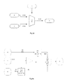
- FIG. 3a shows a simplified diagram of a core logic engine which may be connected in an aircraft control system which may be termed a complex system.
- the core logic engine comprises a processor 10 which obtains input data from a core input/output vector 12 which may itself receive input data from a plurality of inputs, including modules such as proximity sensors (proximity), over communications interfaces (ARINC, CAN) or other modules such as GPIO.
- the core logic engine also comprises a configuration database which comprises a set of truth tables 16 containing instructions for processing the input(s).
- the processor places the outputs into the raw input/output vector 14.
- the outputs may be transferred back to some or all of the modules from which the input data was received, for example to control the complex system.
- Each truth table is processed in the same way regardless of what the state of the inputs and outputs are. For example, it is the task of the core logic input processing to take inputs from the I/O Vector and convert them into a single bit Boolean value: 1 or 0.
- the core logic engine needs a data structure for every logical input and output in order to tell the core logic engine where to obtain its data and where to put its results.
- the data structure may be termed the I/O Vector Map source file 18 and may form part of the configuration database.
- the file may contain a set of collated records (one for each input and each output) and may be held in a CSV file.
- the input and output identifiers e.g. p1_near and WOW1
- each I/O vector does not contain simple Boolean values, e.g.
- the value field might be an integer representing a temperature sensor reading or the value might be a Boolean variable but may still have attribute fields that contain status and validity indications in addition to the data itself.
- one I/O vector format is a vector comprising two structures, each containing two 16 bit integer fields: value and attributes. Attribute Value Bits 31-16 Bits 15 - 0
- the core logic engine of Figure 3a may be incorporated into a landing gear controller and in such a system as shown in Figure 1 , one of the inputs to the system is a proximity sensing component and one example of the I/O vector format for such a component is shown below:
- the value field contains a simple Boolean (perhaps implemented with more than one bit set when TRUE to increase the hamming distance) but the attribute field contains a number of independently set fault flags.
- the identifier p1_near corresponds to the Boolean contained in the value field associated with the first proximity sensing channel. Assuming that the p1_inval is determined by the instantaneous validity (rather than the absence of confirmed faults) it is TRUE if any of the fault flags in the attribute field is set. Other logical inputs might involve detecting when the value field is above or below a fixed threshold (e.g. overcurrent or excessive temperature detectors).
- each record in the I/O Vector Map source file (e.g. p1_near and WOW1) is used to extract a bit-field from an I/O vector entry and convert it into a logical value.
- each record may comprise a name, an index to select the I/O vector element, an instruction (e.g. right shift) to select the least significant bit of the bit-field, an instruction (e.g. bit-mask) to isolate the bit field and a threshold to convert the unsigned integer input into a Boolean value.
- the initial value (init) of each logical variable should also be defined so that the initial state of the system reflects the requirements in the data dictionary.
- the entry for p1_inval indicates that to obtain this logical input the logic engine must fetch from the I/O Vector using index 3 (i.e. the 4 th element).
- the logic engine then converts the fetched value to a Boolean value, for example by performing a right-shift by 16 followed by a mask using bit-wise AND with 0xFFFE.
- the control system accepts data of many types: examples might be a 16-bit field representing angular position in a steering control system or an 8-bit temperature indication.
- a threshold is used in a comparison to convert wider-ranged data into Boolean logical values that can then be used and inputs to combinatorial logic. Examples might be "is steering angle commanded out-of-range", "is temperature above set-point”.
- the threshold value is set at 2.
- the value TRUE is obtained if any attribute bits are set except the LSB (least significant bit).
- the entry for WOW2 indicates that the logic engine should write this output bit to the I/O Vector using index 9, at bit position 1.
- the mask and threshold are superfluous for writing logical outputs but WOW2 is also used as an input to other logic functions so the logic engine needs to know how to fetch it back again.
- the I/O Vector Map and the truth tables together form part of the configuration database for the core logic engine.
- Each truth table may thus be encoded as follows: field Meaning output I/O Vector Map entry used to write output logical value length Number of inputs Input[0] I/O Vector Map entry used to fetch first input value Input[1] I/O Vector Map entry used to fetch second input value ... ... lookup[0] Bit-packed lookup table of the logic function (2 length-3 bytes) lookup[1] Bits 16-31 ... ...
- the set of possible outputs are stored as a vector of bits.
- the advantage of this scheme is determinism: the computation time is independent of the value of the inputs and the logic function being evaluated and the memory usage is only dependent on the number of inputs. It doesn't have to be implemented this way: alternate implementations include storing the list of minterms & searching to see if the current set of inputs matches one on the list. Though compact for sparse functions (output is mostly zero) the size of the list depends on the logic function and the time taken to do the search depends on how many minterms have to be stored. Another alternative is to convert from Boolean equation into a set of instructions for a simple interpreter. Converting the equation into a reverse-polish form would make the implementation simpler but even still exhaustively testing an interpreter is not normally feasible.
- the core logic engine configuration data is an aggregate data structure containing the I/O Vector Map and a binary encoding of all the required truth tables.
- a software tool will be required to build the binary configuration data for the logic engine. If we assume that the output, length and inputs are also encoded as 16 bit integers and that the smallest addressable unit is 8 bits that gives us the possible structure for WOW1 as: field value output 6 length 2 inputs 0 1 lookup 0x4
- the output is in the 7 th row of the I/O Vector Map table so its index would be 6 (assuming C-style indexing from zero).
- the number of inputs is two and that defines the length of the two variable-length parameters: the list of inputs and the output lookup table.
- the inputs are in the first two rows of the I/O Vector Map so the indices are 0 and 1.
- the lookup table is only 4 bits long so can be encoded as a single 16 bit value. This very small truth table can therefore be described by 5 integers: an output index, a length, two input indices and a 4 bit lookup.
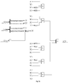
- Figure 3b illustrates the inputs to and resulting output from the processor which relate to a truth table for the tiller steering system.
- Figure 3c illustrates the inputs to and resulting output from the processor which relate to a truth table from the nose wheel steering system. More generally, the tiller steering system and nose wheel steering system could be considered to form a steering system.
- Figure 3b shows four inputs into the processor which are processed according to the relevant truth table which provides an output to the crew alerting system (CAS) via the ARINC.
- the output may be defined as "ML_CAS_TillerSteering_Fail”.
- Three of the inputs are received from three separate fault monitors which are checking for faults on the tiller handle. Examples of these fault monitors include rotational variable differential transformers (RVDT) which are sensors to measure the angular position of the tiller wheel.
- RVDT rotational variable differential transformers
- a third input may be from another sensor which compares the differences between the outputs of the RVDTs and reports if the difference between the angular rotational values from the RVDTs is beyond a threshold value.
- This input may be defined as "ML_RVDT_Reas_Fault_Latch”.
- a fourth input is an output from another truth table which is determining the status of the steerby wire system. This input may be defined as "ML_CAS_SteerByWire_Fail”.
- ML stands for monitor lane. Each component is typically separately connected to both a control lane and a monitor lane. The monitor lane checks the control lane is functioning. The monitor lane may comprise its own separate processor.
- a fault in the steerby wire system is considered to be more serious than a fault in the tiller steering system.
- a fault in the steerby wire system i.e. has a value of 1
- no fault is reported on the tiller steering system. This avoids cluttering the crew alerting system with too many alerting signals.
- a fault will be reported on the tiller steering system unless all the monitors are not returning any faults, i.e. unless all the inputs are 0. This may be expressed as:
- Figure 3c shows six different inputs into the processor which are processed according to the relevant truth table which provides an output to the crew alerting system (CAS) via the ARINC.
- the output is whether or not maintenance is advised and may be defined as "ML_CAS_NWS_Maintenance_Advisory”.
- Three of the inputs are outputs from other truth tables which determine whether or not to send an alert to the CAS if there are faults in the steerby wire system, the rudder steering system and the tiller steering system, respectively. These inputs are termed, "ML_CAS_SteerByWire_Fail”, “ML_CAS_RudderSteering_Fail” and "ML_CAS_TillerSteering_Fail”.
- the output from Figure 3b is an input to the truth table which is processed in Figure 3c .
- Another input is whether or not there is a fault in the monitor lane, "ML_ Fail3".
- a final input is an output from another truth table which determines whether or not to send an alert regarding the fixed gain to the CAS "ML_CAS_FixedGain_Active”.
- an alert is the resulting output.
- the output may also control the system, e.g. control the nose wheel steering or tiller steering.
- the truth tables for a cargo door control unit typically all relate to control of the unit rather than alerting mechanisms. There may be as many as 1500 tables to define all the logical operations for such a unit.
- Figure 3d illustrates the logic which is captured in a truth table for a nose landing gear.
- LGHCU Landing Gear and Hydraulic Control Unit
- the output is 1 to indicate that the nose landing gear door is closed when any one of the results of the AND operations outputs is 1.
- each of the inputs regarding the left hand door need to have a value of 1 and each of the inputs regarding the right hand door need to be set to 0. This is captured in the fourth line from the bottom of the truth table.
- all inputs need to be set to one except the input relating to the validity of the right hand door closing sensor. This is captured in the third line from the bottom of the truth table.
- each of the inputs regarding the right hand door need to have a value of 1 and each of the inputs regarding the left hand door need to be set to 0. This is captured in the fourth line from the top of the truth table.
- all inputs need to be set to one except the input relating to the validity of the left hand door closing sensor. This is captured in the eighth line from the top of the truth table.
- truth tables have the advantage that the output state is explicitly specified, and may therefore be reviewed, for every possible set of input states. Although only a few examples are set out above, all the truth tables should be complete and unambiguous so that they specify once and only once the required output for every permutation of input. "Don't care" entries are not permitted. Furthermore, it is preferable to name the files so that users of the data can navigate easily through the files and understand their purpose, e.g. single output truth tables may have the same name as the output.
- the files may be named to represent the project function that they support rather than the logical function that they implement which should avoid confusion if the content is later changed.
- the comment field should preferably be used in all csv files.
- N is the number of independent inputs. This obviously becomes unmanageable as N is increased.
- a six input table in a small font will fit on one sheet of A4, four pages for eight inputs but for the 13 input functions that have proposed will cover approximately 130 pages and reviewing will be costly and error-prone.
- the favoured method for implementing the logical functions is to weight the inputs in order to calculate the minterm index and then use that index to lookup the output value in a bit-string. This method is very light in computation resources and the index calculation and lookup time are independent of the input states so it is highly deterministic.
- the lookup table is 2 N bits in length, or 2 N-3 bytes. It is possible that there will be 200 logic expressions to evaluate.
- constant data may be stored in one region of memory on the device, such as the upper half of a 16-bit data memory address space. This may then be mapped onto a 32k byte region of FLASH.
- a microcontroller such as a dsPIC33F for example
- constant data may be stored in one region of memory on the device, such as the upper half of a 16-bit data memory address space. This may then be mapped onto a 32k byte region of FLASH.
- dsPIC33F for example, with only 32kbytes of constants easily accessible that suggests a limit of 10 inputs for each truth table so that the truth table is less than 128 bytes.
- the first requirement could be specified as:
- the software shall set Output1 according to the following logic: Switch X is in On position There are any Fail1 failures Output1 False False False True False True False True True True False
- the truth tables may be stored in any format but CSV format files are particularly appropriate for storing truth tables because it is a simple, non-proprietary format and may be configured in subversion.
- the logical expression may be represented in other forms, e.g. excel table or logic gate diagram but the CSV file is taken as the master. An example of a CSV file and its corresponding tabular form are shown below. It will be appreciated that the logical expression may also be represented as a NOR gate, e.g. in Logic Friday:
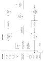
- Figure 4a illustrates one method for verifying the core logic configuration parameters and Figure 4b shows one method for testing a single functional block of the core logic engine.
- Figure 4a shows that the configuration data for the overall system includes source files for an array of truth tables (TT1, TT2, 7), an array of arithmetic operation structures (AO1, AO2, ...) and an array of confirmation logic structures (CNF1, CNF2).
- These source files are typically written as CSV files for the reasons described above and sourced from the SES.
- An I/O vector map is also part of the configuration data but this is not sourced from the SES rather this a design output from the software development as described above.
- the source files and the I/O vector map are input to a logic engine configuration data compiler 20.
- the compiler 20 creates a configuration data file for the logic engine which is sent to a dataload tool(s) 22 for loading the configuration data file onto the target.
- the dataload tool 22 creates configuration data in the flash memory of the target.
- This configuration data in the flash memory may be accessed by a detector 28 on the target to detect errors in data storage or transmission, e.g. level A CRC (cyclic redundancy check).
- the flash memory may be on-chip FLASH within the microcontroller but could alternatively be off-chip memory.
- the configuration data in the flash memory may also be dumped (i.e. stored for further examination) using for example peek/poke techniques 24.
- a memory dump of the configuration data on the target which is read as a binary image by a test script.
- the binary image is decoded by a decoder 26 back to files in the same format as the original source files (e.g. CSV) by another test script.
- the resultant decoded files can then be compared to the source files by reviewers.
- the decoded files include the truth-table, arithmetic operation and confirmer configuration files which were originally determined by Systems Engineers as part of the SES.
- the verification that those source files have been correctly converted and loaded should be agreed by Systems Engineering.
- the decoded files also include the I/O Vector Map which is a software design output. These files should be verified within Software Engineering.
- the verification process is closed loop. No qualified tools are used in the process but there must be independence in the implementation of the configuration compiler and decoder tools otherwise code that is common to both tools might mask a fault in the data.
- the integrity of the configuration data is checked at run-time by the target application.
- Figure 4b shows the procedure for testing any functional block (e.g. a truth-table, a confirmer or an arithmetic function) of the core logic engine.
- the confirmer unlike the truth-tables and arithmetic functions, stores state information in the value stored in an integrator.
- the output of the confirmer therefore depends on the sequence of inputs given to it in contrast to the arithmetic and logic functions where the output only depends on the current input vector.
- Verifying the truth tables preferably involves exhaustively testing every possible input state of every truth table in the configuration data.
- exhaustive testing of all possible inputs values is not proposed.
- a simple weighted sum with a vector of two elements there are 2 16 possible values for each of the inputs, that means there are 2 32 possible input combinations. It is not feasible to test such a large set of input vectors in a reasonable timescale. Instead a small subset of test cases will have to be pre-programmed into the verification script, perhaps some normal, some extreme cases, some corner cases and some repeatable but randomly generated test cases.
- it is not necessary to exhaustively test all possible input sequences for the confirmation function verification even if that were possible. However, it is necessary to demonstrate the correct threshold and saturation behaviour in response to sequences that can be derived from the configuration data.
- the sequence for the test procedure shown in Figure 4b is to read the CSV source file using a read parameter test file 34.
- a model test script 36 which models the core logic function is then configured; the model generating an output for a given set of inputs.
- the I/O vector 12/14 is frozen, i.e. put in a state where the output side is not updated so that inputs to the core logic are fully under the control of the test script.
- the I/O vector map 18 is then read by a read I/O vector map test script 30 in order to obtain the information about where inputs and outputs reside in the I/O vector and how they should be extracted and processed.
- a peek/poke test script 32 is then used to route each input test vector to the correct location on the target.
- the model test script 36 is used to generate the expected output for the input test vector.
- a verify truth table script 38 is used to trigger the logic block on the target (i.e. the core logic engine 10) or we simply wait for the outputs to appear.
- the peek/poke test script 32 is used to capture the outputs in the I/O vector 12/14.
- the verify truth table script 38 compares the target outputs from the peek/poke test script 32 with those from the model test script 36.
- the verify truth table script must be able to single-step the core-logic engine so that the confirmer block is only executed once before its outputs are checked. This is because of the state information in the confirmation function.
- the confirmer-counter can be considered an integrator since it integrates the state of its input.
- the set of behaviours which may be tested should include the following:
- Hardware and software interlocks may be used to ensure that the test-modes are not inadvertently activated during normal operation.
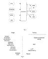
- Figure 5 shows the impact of specifying requirements in truth tables on the overall testing and in particular the impact of revising one of the truth tables.
- the truth table for object Z is revised and is given a new tag "svn rev 101".
- svn stands for subversion, e.g. Apache subversion, which is a software tool for maintaining current and historical versions of files.
- the set of truth tables containing the revised table for object Z is also given a new tag "svn tag: Lane_Function_v02". In other words, the version number has been incremented by one.
- any requirements that specify the modified truth table are updated to refer to the updated revision.
- S3 only SES-88 refers to truth table Z and thus this is updated to state "the software shall compute Z in accordance with Z.csv at svn revision 101 ".
- step S4 any requirements that specified the use of the tag for the set of truth tables containing truth table Z are updated. For example, SES-99 is updated to show that the new tag is being used.
- the issue number for the SES is updated by incrementing the version number by one at step S5.
- the aim is to ensure that the SES is strongly structured and specifies all functional requirements on the software, with allocation at processor lane level. It must specify the state of each software output in terms of all the inputs on which it is dependent, and specify what the output state is for every permutation of those inputs. Furthermore, the aim is to ensure that SES must specify requirements in such a way that they can be flowed straight down to the SRS.
- step S6 The impact of the changes to the SES on the project SRS are shown in steps S6 to S8.
- step S6 the change to the SES issue number implemented at step S5 is reflected in step S6 by changing the SES issue number which is called up by the SRS.
- step S4 any requirements that specified the use of the tag for the set of truth tables containing truth table Z are updated. For example, SRS-44 is updated to show that the new tag is being used.
- the issue number for the SRS is updated by incrementing the version number by one at step S8.
- Step S9 shows that there is a change to the configuration data based on the requirement at SRS-44 to use the tag which refers to the truth table. It is also possible as shown at Step S10 that the low level requirements for the project (Project LLRs) and the software for the Project may need to be changed to reflect the changes to the high level requirements in the SRS. Any low level requirement changes need to be flowed in the low level requirement testing.
- the impact on the testing regime required to generate the necessary traceability is shown in steps S11 to S14.
- the tests which need to be changed are the high level and systems integration tests (HSIT).
- HSIT high level and systems integration tests
- the final verification test e.g. test 99 in the present example
- the issue number of the HSIT test cases is updated at step S14.
- the set of HSIT test cases verify the functional requirements in the Project SRS.
- the tests are typically run on target hardware loaded with the appropriate version of the software. Verification of the project software provides evidence that every functional block in the software, e.g. every core logic truth table, confirm function and custom logic function is correctly implemented against its SRS requirement.
- the first requirement is a derived requirement which is used to justify the use of the SSC and is also the single source requirement to which all the mandatory requirements in the SSC SRS are traced.
- the Project SRS specifies that "the software shall (SRS-55) implement a data-configurable truth table processing function". As shown by the arrows, all the requirements in the Core logic SRS trace back to this derived requirement in the Project SRS.
- the second requirement contains the configuration data associated with the SSC, i.e. the data that will be used by the Project to program the behaviour of the SSC. In Figure 5 , this is shown as "the software shall (SRS044) use svn tag lane_function_v02 as its source”. This requirement in the SRS traces back to the corresponding requirement in the SES. There may also be traces from the Project's software configuration data to this requirement. However, there are no traces to this requirement from the SSC.
- a set of "draft" HSIT test cases will be prepared, to verify the SSC meets its HLRs. These tests are considered “draft” because until an SSC is used in earnest in a Project application, and is running on target hardware, formal HSIT is not meaningful.
- the SSC test cases will be written such that they are configurable, i.e. to be data driven. Then, when the SSC is used by a particular project, the SSC test cases will be configured in a way which is meaningful in the context of the project-specific implementation while still providing verification coverage of the SSC HLRs against which the test case was originally written. Each project must plan and demonstrate how it will achieve verification coverage of the SSC HLRs for the components it uses. Preparation for achieving this must be made by creating an appropriate set of configurable "draft" HSIT test cases for each SSC.
- step S15 is to possibly change the system and equipment tests. It is noted that the HSIT test which tests the impact of the software excludes end-to-end equipment level testing. Such a test remains in the scope of the systems team.
- the validation and testing for a complex system can be simplified by using a shareable software component such as the core logic engine.
- a shareable software component such as the core logic engine.
- Shareable components still require low level requirement tests and results to be achieved on the target processor but where this target processor (e.g. core logic engine) remains constant across projects, the results remain applicable. Therefore the test cases and the test results can be reused.
- the requirements, design and code have all remained unchanged (such as when using a shareable component), the associated reviews (e.g. requirements/design, design/code etc.) all remain valid.
- double-buffering to handle process rate differences and confirmation logic for fault detection and clearing can be dealt with in one place rather than scattered throughout the application code.
- double-buffering of the outputs provides a time-consistent set of outputs for the drives to send.
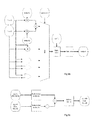
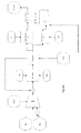
- Figure 6 shows one adaptation of the system of Figure 3a which is suitable in circumstances in which some of the control system outputs are used as inputs to other logical or control functions, perhaps for output limiting, fault detection, or consistency checks, or to prevent duplication within logic implementation.
- the adaptation is also suitable when data items collected from inputs are transmitted, for instance over ARINC, to provide context information to other systems.
- Figure 6 shows that the input and output vectors are replaced with a pair of combined input and output aggregate data structures termed the I/O Vector.
- the I/O vector is double buffered and hence there is a raw I/O vector 120 and a core I/O vector 122.
- the double-buffering of the I/O Vector ensures that a time-consistent snapshot of the inputs and outputs is taken as the input to the core logic component and also supplied to the output drivers.
- a typical timeframe for the double buffering is to take a snapshot of all inputs every 20ms (the proximity sensing software update period) and execute the logic functions on those newly available inputs.
- one of the inputs is whether or not there is a fault in the steerby wire system. This fault is evaluated by considering another truth table.
- the example in Figure 3c there are several inputs which are the results of the evaluations of other truth tables.
- the logic functions which are processed in Figures 3b and 3c are thus examples of cascaded logic.
- all inputs to the core logic are captured in a snapshot of the I/O Vector and all of its outputs are written back to the I/O Vector. In order to avoid the possibility of race conditions the outputs are written back to the Raw I/O Vector and are therefore only available in the next snapshot, made for the next evaluation of the core logic function.
- the value of O1 used as an input to P2 is from the previous cycle therefore the value of the A2 input used to compute O1 is one cycle older than the value of A2 which is also an input to P2.
- the values of A1 and A2 used to compute O1 as an input to P2 are one cycle older than the A4 input.
- test environment allows every possible set of input states to be set up and the output state to be captured.
- test scripts In order to reliably set up the inputs states the test scripts must be able to either disable changes to the I/O Vector either by preventing the copy from the Raw I/O Vector to the (core logic) I/O Vector or by preventing writes to the Raw I/O Vector.
- the implementation should also provide the capability to test the correct function of the cascaded logic blocks to ensure that the coupling between blocks has been correctly implemented in the configuration parameters. This requirement implies that some data propagates from the Raw I/O Vector to the I/O Vector when the core logic function is being tested. This requirement appears to conflict with the requirement to reliably control the input state from the test script.
- Figure 7 shows a variation of the arrangement in Figure 6 which addresses problems in keeping inputs consistent once logic blocks are cascaded.
- the double buffered I/O Vector is partitioned into a public section 124,126 for genuine inputs and outputs (in the above example A1, A2, A4 and 02) and a private section 134,136 for holding intermediate logic variables, namely logic block outputs that can be fed back as inputs (e.g. O1).
- These intermediate variables should only be written and read by the core logic function and are not safe for other components. Ideally they will be hidden or at least obscured from the other components, in contrast to the rest of the I/O Vector which is publically visible throughout the application.
- An extra function is required to only update the intermediate logical variables. This function is termed cascaded core logic 110. Confirmation is unlikely to be required for intermediate values, they are simply temporary variables.
- the public section of the I/O Vector contains a snapshot which is taken before a first pass through the logic table evaluation. This snapshot is then held constant as the core logic iterates through the cascaded logic blocks 110 as many times as necessary to propagate the results through the last cascaded block. In other words, the inputs are effectively temporarily frozen for a fixed number of iterations of the core logic engine. The logic blocks are evaluated and the outputs fed back into the I/O Vector.
- a suitable solution would be to add a variable (e.g. isIOVectorFrozen) which has three states:
- variable can then be accessed via peek-poke to provide exclusive access to the I/O Vector required by the test scripts.
- Such a variable has the capability to disable the main function of the unit so careful consideration must be given to issues such as SEU and inadvertent activation.
- One solution proposed to this problem is to only allow the I/O Vector to be frozen if the engineering peek-poke interface is active. This issue is related to the issue of inadvertent activation of the engineering peek-poke interface itself. This may be achieved by disabling the engineering interface on the target until it receives a key from the test PC. In order to make the probability of interpreting noise as reception of a valid key it should be at least 32 and preferably 64 bits long.
- the access function that returns whether the engineering interface is enabled should check the key each time, rather than storing the result in a local Boolean variable, to improve SEU immunity.
- the key cannot be stored anywhere in the target software so it needs another mechanism for checking for correct reception e.g. by storing the bit-wise inverse (one's complement) or a digest such as a CRC.
- the I/O Vector update code will require a test along the following lines:
- pp_isEnabled() returns a Boolean indication that the engineering interface has been enabled.
- Figure 8b shows a more complex set of cascaded logic blocks having a maximum cascade depth (i.e. maximum precedence rank) of four so that the logic passes through four evaluation loops to allow the outputs to propagate all the way through to output E.
- the nodes T - Z represent logical inputs
- logical blocks A to E represent individual logical functions implementing a single output truth table.
- Nodes C and E are the logical outputs from this cascade.
- the logical variables A, B and D are outputs from one truth table and inputs to another.
- the I/O Vector Map would contain entries for all of A to E and T to Z.
- the logic engine would start by reading in the I/O Vector Map (e.g. using a configuration tool) and would then make a first pass over all of the CSV files that contain the truth tables. At the end of that pass it could establish, for all the entries used in the above logic implementation whether it is a logical input only (T to Z), logical output only (E), or both an input and output (A to D).
- each node it is then possible to recursively compute the precedence rank of each logic block e.g. the precedence rank of E cannot be calculated without first knowing the precedence rank for D.
- the precedence rank of E cannot be calculated without first knowing the precedence rank for D.
- we assign C a precedence rank one higher than its inputs so it is 1, likewise D is 2 and E is 3.
- the output is in the 5 th row of the I/O Vector Map table so its index would be 4 (assuming C-style indexing from zero).
- the precedence rank is three as explained above.
- the number of inputs is three.
- the inputs Y and Z are in the 24 th and 25 th rows of the I/O Vector Map so the indices are 24 and 25.
- This very small truth table can be described by 7 integers: an output index, the precedence rank, a length, three input indices and a C2 bit lookup.
- the "precedence rank" field may not need to be stored as it may not be needed when dependencies can be calculated to order the functional elements such that they were evaluated at the correct sequence for the cascade to function.
- the set of I/O Vector Map entries that are both inputs and outputs to truth tables is exactly the same as the set of intermediate logical variables that must be passed through the I/O Vector double-buffer on each pass through the logic evaluation.
- the logic engine can request that the I/O Vector component copies across these specific bits in order to implement the intermediate logical variables with the rest of the I/O Vector entries unchanged.
- the list can be simply serialised as a length followed by the set of I/O Vector Map indices.
- logic variable C is both an intermediate variable and an output. Its value may vary during the execution of the logic engine whereas all outputs are supposed to form a consistent set after the I/O Vector snapshot is taken for presentation to the logic engine and output drivers. For this reason we will have to enforce a rule and confirm by review that no output from the I/O Vector (to ARINC, GPIO etc.) is also an input to other logic blocks. The situation can be remedied by adding another dummy logic block F (as shown in Figure 8c ) that merely passes on the output of C unchanged. The output driver can use the output of F safely instead, as part of the consistent set, delayed by one core logic cycle.
- Figure 8d shows an example of where sequential (or cascaded) logic is required, namely in edge-detection.
- Figure 8f shows the use of an alias in I/O vector map to prevent the configuration compiler from recognising the data dependency and cascading the logic functions.
- X-_old which is the direct output from X is replaced with an alias X_save.
- the two variables X_save and X_old live in the same bit-field within the I/O Vector.
- X_save is now just an output and X_old is just an input therefore the logic functions are not cascaded.
- the double-buffering within the I/O Vector ensures that the value of X_old really is delayed by one cycle.
- Figure 8g shows a second example of where sequential (or cascaded) logic is required, namely a D-type latch.
- the required function is to gate a fault detection with a pre-condition (a simple AND) but also to latch the output when the pre-condition is removed. This is used to latch a fault result until new data is available to allow it to be set or cleared.
- a pre-condition a simple AND
- Confirmed_fault1_save an extra variable (e.g. Confirmed_fault1_save) will have to be created to store the delayed value as Confirmed_fault1_old would be overwritten as soon as Confirmed_fault1 is calculated in order to propagate the intermediate logic variable into the next logic block in the cascade.
- Confirmed_fault1_save This is essentially the same problem as was outlined in the edge detection example and is solved in the same way.
- Confirmed_fault1_save which is computed using a "delay" truth-table from Confirmed_fault1.
- Confirmed_fault1_old is now an alias for Confirmed_fault1_save and will hold the previous value of Confirmed_fault1 throughout the whole of the cascade evaluation.
- a third example of where sequential (or cascaded) logic is required is a JK latch.
- An SR latch keeps its output in the same state unless the S input is TRUE, in which case the output is TRUE (set), or the R input is TRUE in which case the output is FALSE (reset).
- the S and R inputs are not normally allowed to both be TRUE.
- the behaviour of the JK latch is similar except that the output toggles when both of the S and R inputs are TRUE.
- control function of the core logic transforms the inputs into outputs.
- a simple set of logical functions are likely to be sufficient.
- some arithmetic operations may be required especially for BITE fault detectors.
- Other control systems may require more complex control strategies, such as PID controllers.
- the structure for truth table for the arithmetic evaluation might look like the following: field Meaning output I/O Vector Map entry used to write output logical value Depth or precedence rank Position in cascade of logic and arithmetic blocks shift Right-shift applied to scalar product result threshold Shifted scalar product is compared to this to calculate output length Number of inputs Input1 I/O Vector Map entry used to fetch first input value Weight1 Scalar for first input value Input2 I/O Vector Map entry used to fetch second input value Weight2 Scalar for first second value ... ...
- bit-fields fetched as inputs may have to be sign extended or at least treated as signed values for the purposes of the scalar product calculation. Some of the weights are likely to be negative so signed multiplies, arithmetic shifts and signed comparisons are required.
- Figure 9a shows one example of the internal modules for the core logic processing engine.
- the modules comprise an operation module 52 which processes the truth tables defining the combinatorial logic and evaluates the truth-table logic equations.
- An ALU evaluator 50 which in this arrangement comprises addition, subtraction and multiplication of two inputs, together with Bit-wise AND, OR and XOR of two inputs, complement and shift (as detailed in the table below).
- the confirmer-counter may be considered an integrator since it integrates the state of its input.
- Other components include a multiplexor 54 and a saturate 56 which are explained in more detail below.
- At least one reason for the operations is set out below. It will be appreciated that there may be other reasons for the operations.
- the need for addition is to detect faults such as (Va + Vb) > limit.
- the subtraction is needed to compare two values stored in the I/O Vector against each other rather than against predetermined constants.
- the multiplication operator is needed in the implementation of the steering control algorithm.
- the logical operations are to support logical selection with data wider than a single bit e.g. a multiplexor. It is either impossible (add and subtract) or at best unwieldy (e.g. 16 sets of individual bit operations) to achieve these functions with the existing logic and confirmer operations.
- the I/O Vector is limited to storing 16-bit data. Multiplication is likely to produce a result that has greater precision than is available for storing the result so a means should be provided to select the significant portion of the result. The addition, subtraction, multiplication and shift operations may cause overflow of the signed 16-bit storage for the I/O items. Some means of preventing or mitigating this should be found.
- a and B are inputs
- Y is an output
- k 1 and k 2 are scaling factors.
- the complement operation can be implemented with an XOR with all ones (0xFFFF). An entry may be made in the I/O Vector to hold this value e.g. io_all_ones. In safety critical systems this value will have to be continuously refreshed to mitigate against corruption by SEU (single event upset). This can be done using the existing io_zero and io_unity items by subtraction: io_zero - io_unity.
- the saturation operation takes more computation than selection as does the shift of a 32-bit integer on the dsPIC. It therefore makes sense to compute the weighted add and product results, select the appropriate result and apply the shift and saturation at the end. Ordering the operations in this way means that the bit-wise logical operations also have an optional shift applied to them and, less usefully, the result is saturated to the range of the output field.
- Figure 9b is a variation on the arrangement in Figure 9a .
- the ALU evaluator comprises a weighted sum of two inputs, a product of two inputs together with bit-wise AND, OR and XOR of two inputs.
- the data structure for the implemented arithmetic operations may be specified as: field Meaning output I/O Vector Map entry used to store output value operation Enumeration representing the operation required input1 I/O Vector Map entry used to fetch first input value input2 I/O Vector Map entry used to fetch second input value weight1 Scalar applied to first input value (k 1 ) weight2 Scalar applied to second input value (k 2 ) rshift Right-shift applied to the selected result (k 3 ), 0..16
- I/O Vector Map entries are used to specify the output and both of the inputs for each function.
- the operation is an enumeration as shown in the "Encoding" column specifying the operations, e.g. the enumeration for DOT is zero.
- the first two constants, weight1 and weight2 are used in the dot-product (weighted add) operation described above. For other operations they are unused and should be set to zero.
- the third constant, rshift acts on all results regardless of the operation selected.
- Figure 9c illustrates one example of how the ALU function may be used, e.g. to calculate cabin pressure differential.
- the ALU function may be used, e.g. to calculate cabin pressure differential.
- the following table shows the units and encoding for the inputs and outputs of this function. name meaning i/o units format cp_int Internal cabin pressure input PSI Q7.8 cp_ext External cabin pressure input bar Q1.14 cp_diff Cabin pressure differential output bar Q1.14
- the multiplier for cp_ext is simply -2 12 i.e. -4096.
- An example CSV configuration table for this ALU function is shown below.
- output operation input1 input2 weight 1 weight 2 rshift comment cp_diff dot cp_int cp_ext 18074 -4096 12
- Figure 9d shows a second example; a multiplexor selecting between 16-bit inputs. This could be useful for selecting data that has multiple possible sources e.g. different ARINC busses.
- a and B are the inputs, C is the output and S is the selector.
- One option for the implementation is to have 16 single bit multiplexors, each picking a single bit from the A and B inputs and writing a single bit to the C value. Although feasible this is inefficient in terms of memory and processing and also is not easy to maintain.
- Figure 9e shows how the 16 bit multiplexor of Figure 9d can be implemented using ALU functions by implementing the equivalent formula using multiplications:
- C A & S / B & ! S
- I/O Vector Map entries for the inputs and output are shown below.
- name index position length threshold initial comment A 12 0 16 1 42 mux input B 13 0 16 1 0x42 mux input C 14 0 16 50 0 mux output S 15 0 1 1 0 mux selector nS 15 2 1 1 0 complement of S AS 18 0 16 1 0 A * S BnS 19 0 16 1 0 B * nS
- Figure 4a also shows that the system comprises a set of CSV files relating to confirmation functions, e.g. CNF1.
- a confirmation block is also illustrated in Figure 8g .
- Figures 10a and 10b give more detail of a suitable confirmer block which may be implemented in the system.
- Figure 10a shows the architecture for the confirmer block which is a configurable counter with comparators.
- the confirmer-counter provides programmable increment, decrement, saturation limits and thresholds for setting and clearing the output. When its input is TRUE the counter counts up; when the input is FALSE the counter counts down.
- the counter also has upper and lower saturation values which bound the counter value.
- the output of the confirmer is
- the pair of "on” and “off” thresholds therefore supports hysteresis in the output.
- the counter increment and decrement are not necessarily unity and are also configurable as is the upper saturation limit (the lower limit is fixed at zero). This structure is flexible enough to support behaviours like “confirm fault by three consecutive failures but clear on first good value”, “latch fault after 10 failures” etc.
- the configuration data for the confirmer may be specified using the following data structure: field Meaning output I/O Vector Map entry used to store output confirmation bit input I/O Vector Map entry used to fetch input logical value counter I/O Vector Map entry used to store counter output reset I/O Vector Map entry used to fetch input that forces counter & output to zero inc Counter increment when input is TRUE limit Upper saturation limit for counter value on Output is set to TRUE when counter value reaches or exceeds this dec Counter decrement when input is FALSE off Output is set to FALSE when counter descends down to or below this
- I/O Vector Map entries are used to specify the input and output for each confirmation block.
- a third I/O Vector Map entry is used to hold the counter value between one update cycle and the next, a fourth refers to a signal used to reset the counter and the confirmer output. If no reset signal is needed then a fixed FALSE value in the I/O Vector should be used, for example two I/O items: io_zero and io_one to contain 0 and 1 respectively. Constant values in the I/O Vector may require continuous refreshing to mitigate against corruption caused by SEU.
- the inc and dec parameters are the increment and decrement respectively. Note the decrement value is subtracted from the counter. The limit is the upper bound for the counter value. The "on" and “off” thresholds are applied as described above.
- Figure 10b shows there confirmer blocks, ARM1, ARM_C and FAULT_CONF.
- the three confirmers are identified by their outputs, which are unique to them. They may be specified in a single file (e.g. a CSV file) as shown below or in separate files.
- the arm1 confirmer counts five consecutive TRUE values in arm before setting its output to TRUE.
- the recovery time is only three consecutive FALSE inputs.
- the 100ms referred to in the comment field assumes a 20ms update rate for the core logic engine.
- the arm_c confirmer acts as an SR latch: arm_c is set by any one instance of arm1 so long as the reset signal arm_r is FALSE.
- An alternative implementation of this function can be made using a three input truth-table.
- the fault1_conf confirmer is similar in behaviour to the arm1 confirmer, but uses different inputs and outputs and has the same recovery time as the confirmation time.
- Figure 11 a summarises the method for configuring the core logic data.
- the source files for the configuration data is the following:
- This may then be loaded onto the target using a data loader, including for testing purposes as described in Figure 4a .
- the I/O Vector Map source file is a design output from the software development in contrast to the other CSV files which have come from a common source, the SES.
- the list of CSV source files in the configuration compiler script is also derived from the SES.
- Figure 11b shows how the I/O vector is used to help build the configuration data that embodies the truth tables.
- the core logic engine implements three different functions:
- All three of these functions are programmable functions driven by tables of configuration data.
- the logic function evaluation is limited to implementing combinatorial logic; sequential logic is implemented by writing outputs back into the I/O vector for further processing. Since any combinatorial logic function can be described as a truth table and the SES specifies the logical functions in truth tables this feature can be thought of as a truth-table evaluation engine. There are a number of possible implementations of a truth table and as an example, one possible implementation involves the following operations:
- the minterm indices themselves do not have to be stored when calculating the minterm index because the indices are implicit.
Landscapes
- Engineering & Computer Science (AREA)
- Physics & Mathematics (AREA)
- General Physics & Mathematics (AREA)
- Theoretical Computer Science (AREA)
- Automation & Control Theory (AREA)
- General Engineering & Computer Science (AREA)
- Quality & Reliability (AREA)
- Computer Hardware Design (AREA)
- Aviation & Aerospace Engineering (AREA)
- Radar, Positioning & Navigation (AREA)
- Remote Sensing (AREA)
- Programmable Controllers (AREA)
- Debugging And Monitoring (AREA)
- Testing And Monitoring For Control Systems (AREA)
Applications Claiming Priority (1)
| Application Number | Priority Date | Filing Date | Title |
|---|---|---|---|
| GBGB1320233.8A GB201320233D0 (en) | 2013-11-15 | 2013-11-15 | Method and apparatus for controlling complex systems |
Publications (3)
| Publication Number | Publication Date |
|---|---|
| EP2874065A2 true EP2874065A2 (fr) | 2015-05-20 |
| EP2874065A3 EP2874065A3 (fr) | 2015-10-21 |
| EP2874065B1 EP2874065B1 (fr) | 2017-04-05 |
Family
ID=49883702
Family Applications (1)
| Application Number | Title | Priority Date | Filing Date |
|---|---|---|---|
| EP14193335.8A Active EP2874065B1 (fr) | 2013-11-15 | 2014-11-14 | Procédé et appareil pour commander des systèmes de commande d'aéronef |
Country Status (2)
| Country | Link |
|---|---|
| EP (1) | EP2874065B1 (fr) |
| GB (2) | GB201320233D0 (fr) |
Cited By (6)
| Publication number | Priority date | Publication date | Assignee | Title |
|---|---|---|---|---|
| CN106020800A (zh) * | 2016-05-10 | 2016-10-12 | 中国人民解放军海军航空工程学院 | 一种基于数据库的模拟训练设备操作逻辑建模与驱动方法 |
| CN111886554A (zh) * | 2018-03-22 | 2020-11-03 | 蒂森克虏伯普利斯坦股份公司 | 用于诊断在输入或输出侧使用离散值或离散的值类的功能特征的方法 |
| CN112379977A (zh) * | 2020-07-10 | 2021-02-19 | 中国航空工业集团公司西安飞行自动控制研究所 | 一种基于时间触发的任务级故障处理方法 |
| US20230073618A1 (en) * | 2021-09-02 | 2023-03-09 | Rivian Ip Holdings, Llc | E2e synchronization |
| EP3550391B1 (fr) * | 2018-04-02 | 2023-08-23 | Hamilton Sundstrand Corporation | Tests de logique de reconfiguration autonome pour un actionneur électromécanique |
| CN118722449A (zh) * | 2024-05-22 | 2024-10-01 | 奇瑞新能源汽车股份有限公司 | 车辆的智能座舱系统及车辆 |
Families Citing this family (1)
| Publication number | Priority date | Publication date | Assignee | Title |
|---|---|---|---|---|
| CN111026053B (zh) * | 2019-12-06 | 2021-03-23 | 华北电力科学研究院有限责任公司 | 基于真值表的模块化程控控制方法及装置 |
Family Cites Families (12)
| Publication number | Priority date | Publication date | Assignee | Title |
|---|---|---|---|---|
| EP0541326A3 (en) * | 1991-11-04 | 1993-06-09 | General Electric Company | Determination of control system status |
| US5416719A (en) * | 1992-12-17 | 1995-05-16 | Vlsi Technology, Inc. | Computerized generation of truth tables for sequential and combinatorial cells |
| US6577985B2 (en) * | 2000-12-07 | 2003-06-10 | Eim Company, Inc. | Scalable code absolute logic function (SCALF) encoder |
| US6691287B2 (en) * | 2000-12-14 | 2004-02-10 | Tharas Systems Inc. | Functional verification system |
| JP4343691B2 (ja) * | 2001-11-13 | 2009-10-14 | グッドリッチ・ポンプ・アンド・エンジン・コントロール・システムズ・インコーポレーテッド | ガスタービン・エンジン用故障管理システム |
| US20060200278A1 (en) * | 2005-03-02 | 2006-09-07 | Honeywell International Inc. | Generic software fault mitigation |
| CN100500568C (zh) * | 2007-02-05 | 2009-06-17 | 金坛市西南化工研究所 | 稀土矿硫酸焙烧产物制备超细高纯铈氧化物的方法 |
| US9086459B2 (en) * | 2008-02-21 | 2015-07-21 | Mentor Graphics Corporation | Detection and diagnosis of scan cell internal defects |
| JP5412510B2 (ja) * | 2008-05-19 | 2014-02-12 | ジョンソン コントロールズ テクノロジー カンパニー | 1個のソフトウェアの少なくとも一部を検証するためにテストケースを自動的に形成する方法 |
| CN102024504B (zh) * | 2010-10-21 | 2013-04-24 | 中广核工程有限公司 | 一种适于反应堆保护系统的逻辑测试方法及装置 |
| JP6227239B2 (ja) * | 2011-11-16 | 2017-11-08 | ナブテスコ株式会社 | 航空機制御装置及び航空機制御システム |
| CN103869801A (zh) * | 2012-12-13 | 2014-06-18 | 中广核工程有限公司 | 核电站仪控逻辑功能块的测试方法和系统 |
-
2013
- 2013-11-15 GB GBGB1320233.8A patent/GB201320233D0/en not_active Ceased
-
2014
- 2014-11-14 GB GB1420290.7A patent/GB2522111B/en active Active
- 2014-11-14 EP EP14193335.8A patent/EP2874065B1/fr active Active
Non-Patent Citations (1)
| Title |
|---|
| None |
Cited By (9)
| Publication number | Priority date | Publication date | Assignee | Title |
|---|---|---|---|---|
| CN106020800A (zh) * | 2016-05-10 | 2016-10-12 | 中国人民解放军海军航空工程学院 | 一种基于数据库的模拟训练设备操作逻辑建模与驱动方法 |
| CN111886554A (zh) * | 2018-03-22 | 2020-11-03 | 蒂森克虏伯普利斯坦股份公司 | 用于诊断在输入或输出侧使用离散值或离散的值类的功能特征的方法 |
| CN111886554B (zh) * | 2018-03-22 | 2024-04-16 | 蒂森克虏伯普利斯坦股份公司 | 用于诊断在输入或输出侧使用离散值或离散的值类的功能特征的方法 |
| US12037060B2 (en) | 2018-03-22 | 2024-07-16 | Thyssenkrupp Presta Ag | Method for diagnosing a functionality using discrete values or discrete classes of values on the input or output side |
| EP3550391B1 (fr) * | 2018-04-02 | 2023-08-23 | Hamilton Sundstrand Corporation | Tests de logique de reconfiguration autonome pour un actionneur électromécanique |
| CN112379977A (zh) * | 2020-07-10 | 2021-02-19 | 中国航空工业集团公司西安飞行自动控制研究所 | 一种基于时间触发的任务级故障处理方法 |
| US20230073618A1 (en) * | 2021-09-02 | 2023-03-09 | Rivian Ip Holdings, Llc | E2e synchronization |
| US12341625B2 (en) * | 2021-09-02 | 2025-06-24 | Rivian Ip Holdings, Llc | E2E synchronization |
| CN118722449A (zh) * | 2024-05-22 | 2024-10-01 | 奇瑞新能源汽车股份有限公司 | 车辆的智能座舱系统及车辆 |
Also Published As
| Publication number | Publication date |
|---|---|
| HK1206449A1 (zh) | 2016-01-08 |
| GB2522111B (en) | 2016-01-27 |
| EP2874065A3 (fr) | 2015-10-21 |
| GB201320233D0 (en) | 2014-01-01 |
| GB201420290D0 (en) | 2014-12-31 |
| EP2874065B1 (fr) | 2017-04-05 |
| GB2522111A (en) | 2015-07-15 |
Similar Documents
| Publication | Publication Date | Title |
|---|---|---|
| EP2874065B1 (fr) | Procédé et appareil pour commander des systèmes de commande d'aéronef | |
| Armando et al. | Bounded model checking of software using SMT solvers instead of SAT solvers | |
| EP2876519B1 (fr) | Analyse de sécurité d'un système complexe à l'aide d'arbres de défaillances des composants | |
| Rushby et al. | Modular certification | |
| Ahmed et al. | Formalization of reliability block diagrams in higher-order logic | |
| CN105912413B (zh) | 分析系统、特别是安全关键系统的可用性的方法和装置 | |
| Feiler et al. | Automated fault tree analysis from aadl models | |
| KR101467243B1 (ko) | 비행제어시스템의 자가 진단 테스트 장치 및 이를 이용한 자가 진단 테스트 방법 | |
| Brunel et al. | A viewpoint-based approach for formal safety & security assessment of system architectures | |
| Radu | Reliability and fault tolerance analysis of FPGA platforms | |
| US10877471B2 (en) | Method and apparatus for generating a fault tree for a failure mode of a complex system | |
| US10796315B2 (en) | Automated recertification of a safety critical system | |
| US20110137631A1 (en) | Simulation method, system and program product | |
| Sun et al. | Integrating product-line fault tree analysis into aadl models | |
| EP3519994A1 (fr) | Procédé de modélisation de systèmes techniques | |
| KR20200052129A (ko) | 위성명령 절차서 자동 생성 장치 및 방법 | |
| CN111566625B (zh) | 测试用例生成装置、测试用例生成方法和计算机能读取的记录介质 | |
| US20210026970A1 (en) | Security evaluation server and security evaluation method | |
| EP3140742B1 (fr) | Procédé pour réaliser des calculs à sécurité intégrée | |
| Höfig et al. | MetaFMEA-A framework for reusable FMEAs | |
| Knight et al. | Design fault tolerance | |
| CN119072706A (zh) | 维护成本估计装置和维护成本估计方法 | |
| Mansky et al. | Verifying optimizations for concurrent programs | |
| Sheldon et al. | A case study: validation of guidance control software requirements for completeness, consistency and fault tolerance | |
| Madala et al. | Adsa–association-driven safety analysis to expose unknown safety issues |
Legal Events
| Date | Code | Title | Description |
|---|---|---|---|
| PUAI | Public reference made under article 153(3) epc to a published international application that has entered the european phase |
Free format text: ORIGINAL CODE: 0009012 |
|
| 17P | Request for examination filed |
Effective date: 20141114 |
|
| AK | Designated contracting states |
Kind code of ref document: A2 Designated state(s): AL AT BE BG CH CY CZ DE DK EE ES FI FR GB GR HR HU IE IS IT LI LT LU LV MC MK MT NL NO PL PT RO RS SE SI SK SM TR |
|
| AX | Request for extension of the european patent |
Extension state: BA ME |
|
| PUAL | Search report despatched |
Free format text: ORIGINAL CODE: 0009013 |
|
| AK | Designated contracting states |
Kind code of ref document: A3 Designated state(s): AL AT BE BG CH CY CZ DE DK EE ES FI FR GB GR HR HU IE IS IT LI LT LU LV MC MK MT NL NO PL PT RO RS SE SI SK SM TR |
|
| AX | Request for extension of the european patent |
Extension state: BA ME |
|
| RIC1 | Information provided on ipc code assigned before grant |
Ipc: G05D 1/00 20060101ALI20150911BHEP Ipc: G06F 11/36 20060101AFI20150911BHEP Ipc: G05B 19/418 20060101ALI20150911BHEP |
|
| R17P | Request for examination filed (corrected) |
Effective date: 20160412 |
|
| RBV | Designated contracting states (corrected) |
Designated state(s): AL AT BE BG CH CY CZ DE DK EE ES FI FR GB GR HR HU IE IS IT LI LT LU LV MC MK MT NL NO PL PT RO RS SE SI SK SM TR |
|
| REG | Reference to a national code |
Ref country code: DE Ref legal event code: R079 Ref document number: 602014008275 Country of ref document: DE Free format text: PREVIOUS MAIN CLASS: G06F0011360000 Ipc: G05D0001000000 |
|
| GRAP | Despatch of communication of intention to grant a patent |
Free format text: ORIGINAL CODE: EPIDOSNIGR1 |
|
| RIC1 | Information provided on ipc code assigned before grant |
Ipc: G05B 19/042 20060101ALI20160805BHEP Ipc: G05B 23/02 20060101ALI20160805BHEP Ipc: G06F 11/36 20060101ALI20160805BHEP Ipc: G05D 1/00 20060101AFI20160805BHEP |
|
| INTG | Intention to grant announced |
Effective date: 20160826 |
|
| GRAJ | Information related to disapproval of communication of intention to grant by the applicant or resumption of examination proceedings by the epo deleted |
Free format text: ORIGINAL CODE: EPIDOSDIGR1 |
|
| GRAP | Despatch of communication of intention to grant a patent |
Free format text: ORIGINAL CODE: EPIDOSNIGR1 |
|
| INTG | Intention to grant announced |
Effective date: 20161202 |
|
| INTG | Intention to grant announced |
Effective date: 20161222 |
|
| RBV | Designated contracting states (corrected) |
Designated state(s): AL AT BE BG CH CY CZ DE DK EE ES FI FR GR HR HU IE IS IT LI LT LU LV MC MK MT NL NO PL PT RO RS SE SI SK SM TR |
|
| GRAS | Grant fee paid |
Free format text: ORIGINAL CODE: EPIDOSNIGR3 |
|
| GRAA | (expected) grant |
Free format text: ORIGINAL CODE: 0009210 |
|
| AK | Designated contracting states |
Kind code of ref document: B1 Designated state(s): AL AT BE BG CH CY CZ DE DK EE ES FI FR GR HR HU IE IS IT LI LT LU LV MC MK MT NL NO PL PT RO RS SE SI SK SM TR |
|
| REG | Reference to a national code |
Ref country code: CH Ref legal event code: EP |
|
| REG | Reference to a national code |
Ref country code: AT Ref legal event code: REF Ref document number: 882370 Country of ref document: AT Kind code of ref document: T Effective date: 20170415 |
|
| REG | Reference to a national code |
Ref country code: IE Ref legal event code: FG4D |
|
| REG | Reference to a national code |
Ref country code: DE Ref legal event code: R096 Ref document number: 602014008275 Country of ref document: DE |
|
| REG | Reference to a national code |
Ref country code: NL Ref legal event code: MP Effective date: 20170405 |
|
| REG | Reference to a national code |
Ref country code: LT Ref legal event code: MG4D |
|
| REG | Reference to a national code |
Ref country code: AT Ref legal event code: MK05 Ref document number: 882370 Country of ref document: AT Kind code of ref document: T Effective date: 20170405 |
|
| PG25 | Lapsed in a contracting state [announced via postgrant information from national office to epo] |
Ref country code: NL Free format text: LAPSE BECAUSE OF FAILURE TO SUBMIT A TRANSLATION OF THE DESCRIPTION OR TO PAY THE FEE WITHIN THE PRESCRIBED TIME-LIMIT Effective date: 20170405 |
|
| REG | Reference to a national code |
Ref country code: FR Ref legal event code: PLFP Year of fee payment: 4 |
|
| PG25 | Lapsed in a contracting state [announced via postgrant information from national office to epo] |
Ref country code: AT Free format text: LAPSE BECAUSE OF FAILURE TO SUBMIT A TRANSLATION OF THE DESCRIPTION OR TO PAY THE FEE WITHIN THE PRESCRIBED TIME-LIMIT Effective date: 20170405 Ref country code: FI Free format text: LAPSE BECAUSE OF FAILURE TO SUBMIT A TRANSLATION OF THE DESCRIPTION OR TO PAY THE FEE WITHIN THE PRESCRIBED TIME-LIMIT Effective date: 20170405 Ref country code: ES Free format text: LAPSE BECAUSE OF FAILURE TO SUBMIT A TRANSLATION OF THE DESCRIPTION OR TO PAY THE FEE WITHIN THE PRESCRIBED TIME-LIMIT Effective date: 20170405 Ref country code: HR Free format text: LAPSE BECAUSE OF FAILURE TO SUBMIT A TRANSLATION OF THE DESCRIPTION OR TO PAY THE FEE WITHIN THE PRESCRIBED TIME-LIMIT Effective date: 20170405 Ref country code: NO Free format text: LAPSE BECAUSE OF FAILURE TO SUBMIT A TRANSLATION OF THE DESCRIPTION OR TO PAY THE FEE WITHIN THE PRESCRIBED TIME-LIMIT Effective date: 20170705 Ref country code: LT Free format text: LAPSE BECAUSE OF FAILURE TO SUBMIT A TRANSLATION OF THE DESCRIPTION OR TO PAY THE FEE WITHIN THE PRESCRIBED TIME-LIMIT Effective date: 20170405 Ref country code: GR Free format text: LAPSE BECAUSE OF FAILURE TO SUBMIT A TRANSLATION OF THE DESCRIPTION OR TO PAY THE FEE WITHIN THE PRESCRIBED TIME-LIMIT Effective date: 20170706 |
|
| PG25 | Lapsed in a contracting state [announced via postgrant information from national office to epo] |
Ref country code: BG Free format text: LAPSE BECAUSE OF FAILURE TO SUBMIT A TRANSLATION OF THE DESCRIPTION OR TO PAY THE FEE WITHIN THE PRESCRIBED TIME-LIMIT Effective date: 20170705 Ref country code: RS Free format text: LAPSE BECAUSE OF FAILURE TO SUBMIT A TRANSLATION OF THE DESCRIPTION OR TO PAY THE FEE WITHIN THE PRESCRIBED TIME-LIMIT Effective date: 20170405 Ref country code: PL Free format text: LAPSE BECAUSE OF FAILURE TO SUBMIT A TRANSLATION OF THE DESCRIPTION OR TO PAY THE FEE WITHIN THE PRESCRIBED TIME-LIMIT Effective date: 20170405 Ref country code: IS Free format text: LAPSE BECAUSE OF FAILURE TO SUBMIT A TRANSLATION OF THE DESCRIPTION OR TO PAY THE FEE WITHIN THE PRESCRIBED TIME-LIMIT Effective date: 20170805 Ref country code: LV Free format text: LAPSE BECAUSE OF FAILURE TO SUBMIT A TRANSLATION OF THE DESCRIPTION OR TO PAY THE FEE WITHIN THE PRESCRIBED TIME-LIMIT Effective date: 20170405 Ref country code: SE Free format text: LAPSE BECAUSE OF FAILURE TO SUBMIT A TRANSLATION OF THE DESCRIPTION OR TO PAY THE FEE WITHIN THE PRESCRIBED TIME-LIMIT Effective date: 20170405 |
|
| REG | Reference to a national code |
Ref country code: DE Ref legal event code: R097 Ref document number: 602014008275 Country of ref document: DE |
|
| PG25 | Lapsed in a contracting state [announced via postgrant information from national office to epo] |
Ref country code: RO Free format text: LAPSE BECAUSE OF FAILURE TO SUBMIT A TRANSLATION OF THE DESCRIPTION OR TO PAY THE FEE WITHIN THE PRESCRIBED TIME-LIMIT Effective date: 20170405 Ref country code: DK Free format text: LAPSE BECAUSE OF FAILURE TO SUBMIT A TRANSLATION OF THE DESCRIPTION OR TO PAY THE FEE WITHIN THE PRESCRIBED TIME-LIMIT Effective date: 20170405 Ref country code: SK Free format text: LAPSE BECAUSE OF FAILURE TO SUBMIT A TRANSLATION OF THE DESCRIPTION OR TO PAY THE FEE WITHIN THE PRESCRIBED TIME-LIMIT Effective date: 20170405 Ref country code: CZ Free format text: LAPSE BECAUSE OF FAILURE TO SUBMIT A TRANSLATION OF THE DESCRIPTION OR TO PAY THE FEE WITHIN THE PRESCRIBED TIME-LIMIT Effective date: 20170405 Ref country code: EE Free format text: LAPSE BECAUSE OF FAILURE TO SUBMIT A TRANSLATION OF THE DESCRIPTION OR TO PAY THE FEE WITHIN THE PRESCRIBED TIME-LIMIT Effective date: 20170405 |
|
| PLBE | No opposition filed within time limit |
Free format text: ORIGINAL CODE: 0009261 |
|
| STAA | Information on the status of an ep patent application or granted ep patent |
Free format text: STATUS: NO OPPOSITION FILED WITHIN TIME LIMIT |
|
| PG25 | Lapsed in a contracting state [announced via postgrant information from national office to epo] |
Ref country code: IT Free format text: LAPSE BECAUSE OF FAILURE TO SUBMIT A TRANSLATION OF THE DESCRIPTION OR TO PAY THE FEE WITHIN THE PRESCRIBED TIME-LIMIT Effective date: 20170405 Ref country code: SM Free format text: LAPSE BECAUSE OF FAILURE TO SUBMIT A TRANSLATION OF THE DESCRIPTION OR TO PAY THE FEE WITHIN THE PRESCRIBED TIME-LIMIT Effective date: 20170405 |
|
| 26N | No opposition filed |
Effective date: 20180108 |
|
| PG25 | Lapsed in a contracting state [announced via postgrant information from national office to epo] |
Ref country code: SI Free format text: LAPSE BECAUSE OF FAILURE TO SUBMIT A TRANSLATION OF THE DESCRIPTION OR TO PAY THE FEE WITHIN THE PRESCRIBED TIME-LIMIT Effective date: 20170405 |
|
| PG25 | Lapsed in a contracting state [announced via postgrant information from national office to epo] |
Ref country code: MC Free format text: LAPSE BECAUSE OF FAILURE TO SUBMIT A TRANSLATION OF THE DESCRIPTION OR TO PAY THE FEE WITHIN THE PRESCRIBED TIME-LIMIT Effective date: 20170405 |
|
| PG25 | Lapsed in a contracting state [announced via postgrant information from national office to epo] |
Ref country code: CH Free format text: LAPSE BECAUSE OF NON-PAYMENT OF DUE FEES Effective date: 20171130 Ref country code: LI Free format text: LAPSE BECAUSE OF NON-PAYMENT OF DUE FEES Effective date: 20171130 |
|
| PG25 | Lapsed in a contracting state [announced via postgrant information from national office to epo] |
Ref country code: LU Free format text: LAPSE BECAUSE OF NON-PAYMENT OF DUE FEES Effective date: 20171114 |
|
| REG | Reference to a national code |
Ref country code: BE Ref legal event code: MM Effective date: 20171130 |
|
| REG | Reference to a national code |
Ref country code: IE Ref legal event code: MM4A |
|
| PG25 | Lapsed in a contracting state [announced via postgrant information from national office to epo] |
Ref country code: MT Free format text: LAPSE BECAUSE OF NON-PAYMENT OF DUE FEES Effective date: 20171114 |
|
| REG | Reference to a national code |
Ref country code: FR Ref legal event code: PLFP Year of fee payment: 5 |
|
| PG25 | Lapsed in a contracting state [announced via postgrant information from national office to epo] |
Ref country code: IE Free format text: LAPSE BECAUSE OF NON-PAYMENT OF DUE FEES Effective date: 20171114 |
|
| PG25 | Lapsed in a contracting state [announced via postgrant information from national office to epo] |
Ref country code: BE Free format text: LAPSE BECAUSE OF NON-PAYMENT OF DUE FEES Effective date: 20171130 |
|
| PG25 | Lapsed in a contracting state [announced via postgrant information from national office to epo] |
Ref country code: HU Free format text: LAPSE BECAUSE OF FAILURE TO SUBMIT A TRANSLATION OF THE DESCRIPTION OR TO PAY THE FEE WITHIN THE PRESCRIBED TIME-LIMIT; INVALID AB INITIO Effective date: 20141114 |
|
| PG25 | Lapsed in a contracting state [announced via postgrant information from national office to epo] |
Ref country code: CY Free format text: LAPSE BECAUSE OF FAILURE TO SUBMIT A TRANSLATION OF THE DESCRIPTION OR TO PAY THE FEE WITHIN THE PRESCRIBED TIME-LIMIT Effective date: 20170405 |
|
| PG25 | Lapsed in a contracting state [announced via postgrant information from national office to epo] |
Ref country code: MK Free format text: LAPSE BECAUSE OF FAILURE TO SUBMIT A TRANSLATION OF THE DESCRIPTION OR TO PAY THE FEE WITHIN THE PRESCRIBED TIME-LIMIT Effective date: 20170405 |
|
| PG25 | Lapsed in a contracting state [announced via postgrant information from national office to epo] |
Ref country code: TR Free format text: LAPSE BECAUSE OF FAILURE TO SUBMIT A TRANSLATION OF THE DESCRIPTION OR TO PAY THE FEE WITHIN THE PRESCRIBED TIME-LIMIT Effective date: 20170405 |
|
| PG25 | Lapsed in a contracting state [announced via postgrant information from national office to epo] |
Ref country code: PT Free format text: LAPSE BECAUSE OF FAILURE TO SUBMIT A TRANSLATION OF THE DESCRIPTION OR TO PAY THE FEE WITHIN THE PRESCRIBED TIME-LIMIT Effective date: 20170405 |
|
| PG25 | Lapsed in a contracting state [announced via postgrant information from national office to epo] |
Ref country code: AL Free format text: LAPSE BECAUSE OF FAILURE TO SUBMIT A TRANSLATION OF THE DESCRIPTION OR TO PAY THE FEE WITHIN THE PRESCRIBED TIME-LIMIT Effective date: 20170405 |
|
| REG | Reference to a national code |
Ref country code: DE Ref legal event code: R081 Ref document number: 602014008275 Country of ref document: DE Owner name: ULTRA PCS LTD., CHELTENHAM, GB Free format text: FORMER OWNER: ULTRA ELECTRONICS LIMITED, GREENFORD, MIDDLESEX, GB |
|
| PGFP | Annual fee paid to national office [announced via postgrant information from national office to epo] |
Ref country code: FR Payment date: 20250908 Year of fee payment: 12 |
|
| PGFP | Annual fee paid to national office [announced via postgrant information from national office to epo] |
Ref country code: DE Payment date: 20250916 Year of fee payment: 12 |