EP2874191A2 - Hybridvorrichtung, die ein thermoelektrisches Modul umfasst, insbesondere zur Stromerzeugung in einem Kraftfahrzeug, und Wärmetauscher - Google Patents
Hybridvorrichtung, die ein thermoelektrisches Modul umfasst, insbesondere zur Stromerzeugung in einem Kraftfahrzeug, und Wärmetauscher Download PDFInfo
- Publication number
- EP2874191A2 EP2874191A2 EP20140193383 EP14193383A EP2874191A2 EP 2874191 A2 EP2874191 A2 EP 2874191A2 EP 20140193383 EP20140193383 EP 20140193383 EP 14193383 A EP14193383 A EP 14193383A EP 2874191 A2 EP2874191 A2 EP 2874191A2
- Authority
- EP
- European Patent Office
- Prior art keywords
- cold
- zone
- fluid
- circuit
- hybrid device
- Prior art date
- Legal status (The legal status is an assumption and is not a legal conclusion. Google has not performed a legal analysis and makes no representation as to the accuracy of the status listed.)
- Granted
Links
Images


Classifications
-
- H—ELECTRICITY
- H10—SEMICONDUCTOR DEVICES; ELECTRIC SOLID-STATE DEVICES NOT OTHERWISE PROVIDED FOR
- H10N—ELECTRIC SOLID-STATE DEVICES NOT OTHERWISE PROVIDED FOR
- H10N10/00—Thermoelectric devices comprising a junction of dissimilar materials, i.e. devices exhibiting Seebeck or Peltier effects
- H10N10/10—Thermoelectric devices comprising a junction of dissimilar materials, i.e. devices exhibiting Seebeck or Peltier effects operating with only the Peltier or Seebeck effects
- H10N10/13—Thermoelectric devices comprising a junction of dissimilar materials, i.e. devices exhibiting Seebeck or Peltier effects operating with only the Peltier or Seebeck effects characterised by the heat-exchanging means at the junction
-
- H—ELECTRICITY
- H10—SEMICONDUCTOR DEVICES; ELECTRIC SOLID-STATE DEVICES NOT OTHERWISE PROVIDED FOR
- H10N—ELECTRIC SOLID-STATE DEVICES NOT OTHERWISE PROVIDED FOR
- H10N10/00—Thermoelectric devices comprising a junction of dissimilar materials, i.e. devices exhibiting Seebeck or Peltier effects
- H10N10/10—Thermoelectric devices comprising a junction of dissimilar materials, i.e. devices exhibiting Seebeck or Peltier effects operating with only the Peltier or Seebeck effects
- H10N10/17—Thermoelectric devices comprising a junction of dissimilar materials, i.e. devices exhibiting Seebeck or Peltier effects operating with only the Peltier or Seebeck effects characterised by the structure or configuration of the cell or thermocouple forming the device
Definitions
- the present invention relates to a hybrid device comprising a thermoelectric module, in particular for generating an electric current in a motor vehicle and a heat exchanger.
- heat exchangers comprising, at a first zone, so-called electrical thermo elements, for generating an electric current in the presence of a temperature gradient between two of their opposite faces according to the known phenomenon as the Seebeck effect.
- the exchanger is configured to be located at a front face of the vehicle so as to be traversed by the flow of air flowing through a radiator grille of the vehicle.
- the exchanger then comprises a stack of fins, one of which is intended to be traversed by the ambient air, and another group is thermally bonded to tubes, intended for the circulation of a fluid of a cooling loop. of the vehicle engine.
- the electrical thermo elements are sandwiched between the fins of each group and the tubes so as to be subjected to a temperature gradient from the temperature difference between the fins.
- Such devices may comprise, at a second zone, a portion devoid of electric thermo elements so as to allow a heat exchange between the ambient air and the cooling fluid.
- the first and second zones are then located next to each other so that the ambient air passes through the two zones in parallel.
- the invention aims to improve the situation and concerns for this purpose a hybrid device comprising, at a first zone, at least one thermoelectric element for generating an electric current from a temperature gradient applied between two of its active faces, said device comprising a first circuit, called hot, able to allow the circulation of a first fluid, said hot, and a second circuit, said to be cold, capable of allowing the circulation of a second fluid, said cold, lower temperature than that of the hot fluid so as to create said gradient, said hybrid device comprising a second zone so as to allow a heat exchange between the cold fluid and the hot fluid, said hybrid device being arranged so that the hot fluid crosses it by traversing a single direction, said first direction, said first zone and said second zone being located in series according to the first direction.
- a hybrid device comprising, at a first zone, at least one thermoelectric element for generating an electric current from a temperature gradient applied between two of its active faces, said device comprising a first circuit, called hot, able to allow the circulation of a first fluid, said hot,
- the first zone in series with respect to the second zone in the direction of circulation of the hot fluid, it is possible to decorate the depth used for the first zone, that is to say the zone having Electric thermo element and the depth of the second zone, that is to say, the area dedicated to heat exchange.
- the first zone will also be present on the entire lateral surface of the device, that is to say a surface perpendicular to the first direction, which will allow to dedicate the entire flow of hot fluid.
- the unique direction given to the hot fluid further limits the loss of charge, which will facilitate the use of said device over a larger range of engine operation in the case of application to exhaust gas.
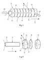
- thermoelectric module 10 here comprises an element of a first circuit 1, said to be hot, capable of allowing the circulation of a first fluid, said to be hot, in particular of the exhaust gases of an engine, and an element 15 of a second circuit 2, said cold, capable of allowing the circulation of a second fluid, said cold, including a heat transfer fluid of a cooling circuit, lower temperature than the hot fluid.
- Said cold fluid may have a higher heat exchange coefficient to said hot fluid, in particular being provided liquid.
- the electric thermo elements are, for example, ring-shaped. They are capable of generating an electric current under the action of a temperature gradient exerted between two of their faces, one 4a, said first face, being defined by an outer periphery surface, cylindrical, and the other 4b , said second face, being defined by an inner periphery surface, cylindrical.
- Said first and second faces 4a, 4b are, for example, of circular section. More generally, any section of rounded and / or polygonal shape is possible.
- the first face 4a is in heat exchange relation with the hot circuit and the second face 4b is in heat exchange relationship with the cold circuit.
- Such elements operate, according to the Seebeck effect, by making it possible to create an electric current in a load connected between said faces 4a, 4b subjected to the temperature gradient.
- such elements consist, for example, of Bismuth and Tellurium (Bi 2 Te 3 ).
- thermoelectric elements may be, for a first part, elements 3p of a first type, said P, for establishing a difference in electric potential in a direction, said positive, when they are subjected to a temperature gradient given, and, for the other part, elements 3n of a second type, said N, allowing the creation of a difference of electric potential in an opposite direction, said negative, when they are subjected to the same temperature gradient .
- thermoelectric elements 3 shown are formed of a ring in one piece. They may however be formed of several pieces each forming an angular portion of the ring.
- the first surface 4a has, for example, a radius of between 1.5 and 4 times the radius of the second surface 4b. It may be a radius equal to about 2 times that of second surface 4b.
- thermoelectric element has, for example, two opposite planar faces 6a, 6b opposite.
- the ring constituting the thermoelectric element is of rectangular annular section.
- thermoelectric elements 3 are arranged, for example, in the longitudinal extension of one another, in particular in a coaxial manner, and the P-type electrical thermoelectric elements alternate with the N-type thermoelectric elements, in a direction D , said third direction D. They are, in particular, identical in shape and size. However, they may have a thickness, that is to say a dimension between their two flat faces, different from one type to the other, especially according to their electrical conductivity.
- thermoelectric elements 3 are, for example, grouped in pairs, each pair being formed of a said P-type thermoelectric element and a said N-type thermoelectric element, and the said module is configured to allow a circulation of current between the first surfaces of the thermoelectric elements of the same pair and a flow of current between the second surfaces of each of the electric thermo elements of the same pair and the thermoelectric element adjacent to the neighboring pair. In this way, a series circulation of the electric current is ensured between the electric thermoelectric elements 3 arranged next to one another in the direction D.
- said electric thermo elements 3 are arranged relative to each other so that their first and / or second surface 4a, 4b are in the extension. one from the other. Said first and / or second surfaces 4a, 4b are thus inscribed, for example, in a surface generated by a straight line.
- Said element 15 of the cold circuit 2 cold liquid circulation is in contact with said second surface 4b of said electric thermo elements 3.
- Said element 15 of the cold circuit 2 is, for example, circular section.
- said module comprises tubes, said first tubes 12, cold liquid circulation in said element of the cold circuit.
- At least two thermoelectric elements of different type are mounted on said first tubes 12.
- the first tubes 12 are, in particular, metallic. They define at least partly a first part 7 of the cold circuit 2.
- Said module 10 may furthermore comprise electrical insulation means 20 arranged between two faces 6a, 6b opposite neighboring thermoelectric elements 3 in the third direction D corresponding to the direction of longitudinal extension of the first tube 12.
- the electric thermo elements 3, and the electrical insulation means 20 are assembled, alternately, on the first tubes 12 for cold fluid circulation.
- Said module may further comprise first electrical connection means connecting the outer periphery surfaces 4a of two of said adjacent and different types of thermoelectric elements, and second electrical connection means connecting the inner periphery surfaces 4b of two of said elements. electric thermo, provided adjacent and of different types.
- said module is configured so that the hot circuit makes it possible to establish a heat exchange between said first face 4a and the hot fluid, circulating here outside of said thermoelectric elements 3 in the hot circuit 1, according to the arrow illustrated 102 and so that the cold circuit makes it possible to establish a heat exchange between said second face 4b and the cold fluid, circulating here in the first part 7 of the cold circuit 2 according to the illustrated arrow 100.
- thermo elements electrical, thus promotes the exchange between the electric thermo elements 3, and the fluid having the lowest heat exchange coefficient, here, the exhaust gas.
- Said module is furthermore configured here so that, at said module, said hot fluid and said second fluid circulate transversely, in particular orthogonal, with respect to each other, as illustrated by the orientation of the arrows 100, 102.
- Such a configuration promotes integration of the module into its environment by decreasing the quantities of material involved.
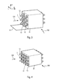
- a beam of the hybrid device of the invention comprising, at a first zone 91, a plurality of said modules 10 is illustrated in FIGS. Figures 3 and 4 .
- Such a hybrid device comprises at least two of said modules forming a row of modules and at least two of said modules forming a row of modules.
- the modules 10 belonging to the same row of modules are spaced apart from each other in a first direction L and located at the same level in a second direction H transverse to the first.
- the modules 10 belonging to the same row of modules are spaced apart from each other in the second direction H and situated at the same level in the first direction L.
- the device is arranged for the hot fluid to pass through it by traversing a only direction, that is to say here the first direction L if not to bypass said modules 10.
- the first direction L is in particular parallel to the direction of circulation of the hot fluid 102 in the hybrid device and the second direction H is perpendicular to the first direction L and the flow direction of the cold fluid 100 in the hybrid device.
- the modules 10 thus extend in the device in the third direction D and are arranged in a row along the first direction L and in a row along the second direction H.
- the first direction L, the second direction H and / or the third direction D are for example perpendicular to each other as illustrated in the drawings. Figures 3 and 4 .
- the neighboring modules 10 of two adjacent rows are offset relative to each other in the second direction H in addition to being shifted in the first direction L so as to be arranged in staggered rows.
- Neighboring modules 10 of two adjacent rows are called modules 10 which have the same position in their respective rows, that is to say the first modules of the rows starting from the bottom in the second direction H, the modules located just at the above the first modules etc.
- the first zone 91 of the device of the invention comprises four rows of three modules 10 and six rows of two modules 10. It could of course include a different number of rows and / or rows as well as modules 10 per row and / or or modules 10 per rank.
- adjacent modules 10 of two adjacent rows are located at the same level relative to each other in the second direction H so as to be arranged in a grid.
- the adjacent modules 10 of two adjacent rows are located at the same level in the first direction L so as to be arranged in a grid.
- the number of modules 10 that includes a row is equal to the number of rows and the number of modules 10 that includes a row is equal to the number of rows.
- the first zone 91 of the device comprises four rows of three modules 10 each and three rows of four modules 10 each but it could of course comprise a different number of rows and / or rows as well as modules 10 in rows and / or modules 10 by rank.
- the hybrid device 80 comprises a second zone 92 allowing a heat exchange between the cold fluid and the hot fluid as illustrated in FIGS. Figures 5 and 6 .
- the device 80 according to the invention thus has a function of generating electricity at its first zone 91 and heat exchanger at its second zone 92.
- Said first zone 91 and said second zone 92 are located in series. according to the first direction L.
- the first zone 91 is located upstream of the second zone 92 in the direction of circulation of the hot fluid, that is to say in the first direction L.
- the hot circuit and the cold circuit are arranged so that the hot fluid circulates transversely to the cold fluid in the hybrid device, in particular in said first zone 91.
- Said second zone 92 comprises a second portion 4 of the cold circuit.
- said hot circuit and the second part 4 of said cold circuit are directly in contact so as to allow a heat exchange between the cold fluid and the hot fluid.
- the second part of the cold circuit comprises, for example tubes, said second tubes 13, for circulating the cold fluid.
- the first zone 91 here comprises several rows of modules 10 and several ranks of module 10.
- the second zone 92 here comprises a single row of tubes 13, said second tubes 13 being spaced apart in the second direction H and located at the level of a face of the device through which the hot fluid exits the device.
- the tubes 13 thus form a row of tubes 13 in which at least two of said tubes 13, here three tubes 13, are spaced from each other in the second direction H, preferably at the same spacing as that of the second tubes 13 of the first zone 91.
- the second zone 92 here comprises a single row of tubes 13 but it could of course comprise a different number of tubes 13.
- the hybrid device 80 may comprise an inlet manifold 72 of the cold fluid in the device 80 and an outlet manifold 71 of the cold fluid of the device, the cold circuit comprising several sub-circuits 73 for the passage of the fluid cold through the modules 10 between the input manifold 72 and the outlet manifold 71, the sub-circuits 73 being parallel to one another.
- first part 7 of the cold circuit and the second part 4 of the cold circuit are linked.
- the sub-circuits 73 of the first part 7 of the cold circuit and the sub-circuits 73 of the second part 4 of the cold circuit communicate with each other so that it is the same fluid which enters the device through the collector box of 72, runs through the first part 7 of the cold circuit, the second part 4 of the cold circuit and leaves the device through the outlet manifold 71 as visible on the figure 5 .
- the outlet manifold 71 of the cold fluid is here located at the second zone 91 and the inlet manifold 72 of the cold fluid is here located at the level of the row of modules 10 intended to come into contact first with said hot fluid, that is to say the row of modules 10 located closest to the inlet face 81.
- the manifold inlet 72 and the outlet manifold 71 are located on the same side of the device , here a lateral side of the device with respect to the inlet face of the hot fluid in the device.
- Each of the passage sub-circuits 73 comprises the adjacent modules 10 of each of the rows. Thus there is as much independent sub-circuit as modules 10 per row.
- Each of the sub-circuits 73 here connects successively the neighboring rows in a coil.
- the cold fluid arrives in the inlet manifold 72, enters one of the modules 10 of the row located at the inlet manifold 72, that is to say, it enters the first part 7 the cold circuit, the cross in the direction of the length in the third direction D as seen above, passes into a module 10 adjacent to an adjacent row and crosses it in the same direction but in the opposite direction.
- the cold fluid continues its path until it reaches the tube near the tube row 13 of the second zone 92, that is to say until reaching the second part 4 of the cold circuit located in the second zone, before exiting the hybrid device through the outlet manifold 71. It is understood here that the first part 7 of the cold circuit is upstream of the second part 4 of the cold circuit with respect to the circulation of the cold fluid.
- the first part 7 of the cold circuit and the second part 4 of the cold circuit are thermally independent. It is understood here that the device is arranged to circulate the cold fluid in the first zone 91 and in the second zone independently.
- the subcircuits of the first part 7 of the cold circuit are then independent of the subcircuits of the second part 4 of the cold circuit.
- Each zone will include its own cold fluid inlet manifold and its own cold fluid outlet manifold similar to that previously described.
- the first part 7 of the cold circuit and the second part 4 of the cold circuit here comprise the same number of passage subcircuits.
- the passage sub-circuits 73 comprise tubings 74 interconnecting the adjacent modules 10 of two different rows at their ends. These pipes have in particular the shape of a U.
- the hybrid device according to the invention also comprises an inlet manifold 83 of the hot fluid in the device located opposite the inlet face of the hot fluid through the modules 10, and an outlet manifold 84 of the hot fluid, located opposite the inlet manifold 83 of the hot fluid in the hybrid device.
- each of the modules may advantageously comprise secondary exchange surfaces 9, in particular fins 104, with the hot fluid.
- Said fins 104 are arranged, for example, transversely, in particular radially to said electric thermo elements 3. They are here positioned parallel to each other with a spacing allowing a good heat exchange with the hot fluid while limiting the losses of charges.
- Said fins 104 may be off-center with respect to said thermoelectric elements 3, in particular elongated on the side of the arrival of the hot fluid.
- Said fins 104 are, for example, corrugated, perforated and / or louvered. The fact that the fins are corrugated and / or perforated and / or louvers improves the heat exchange, including increasing the exchange surfaces and disrupting the flow of hot fluid.
- the fins are, in particular, metal.
- Said fins 104 advantageously connect the modules together so that they are traversed by said modules. In these figures, only one of said rows is illustrated. They can also connect together the tubes 13 of the second part of the cold circuit.
- the modules may be connected together in series and / or in parallel, by connections, not shown, located at their longitudinal ends.
- the secondary exchange surfaces 9 may include a catalytic coating to provide catalytic conversion of toxic components of the hot fluid.
- said module can in this way equip a catalytic converter in addition or substitution of the components conventionally used for catalysis in such equipment.
- the secondary exchange surfaces of the first zone and that of the second zone are thermally and electrically independent.
- such a device may be configured to be positioned in a motor vehicle exhaust gas conduit so that said secondary exchange surfaces are swept by said gases.
- the gases are intended to be channeled through the fins by the exhaust pipe itself while the circulation of the second fluid can be done by the inlet / outlet manifolds positioned laterally, where a great simplicity of integration.
Landscapes
- Heat-Exchange Devices With Radiators And Conduit Assemblies (AREA)
- Air-Conditioning For Vehicles (AREA)
- Electric Propulsion And Braking For Vehicles (AREA)
Applications Claiming Priority (1)
| Application Number | Priority Date | Filing Date | Title |
|---|---|---|---|
| FR1361255A FR3013433B1 (fr) | 2013-11-18 | 2013-11-18 | Dispositif hybride comprenant un module thermo electrique, notamment destine a generer un courant electrique dans un vehicule automobile, et un echangeur de chaleur de chaleur |
Publications (3)
| Publication Number | Publication Date |
|---|---|
| EP2874191A2 true EP2874191A2 (de) | 2015-05-20 |
| EP2874191A3 EP2874191A3 (de) | 2015-06-17 |
| EP2874191B1 EP2874191B1 (de) | 2019-05-08 |
Family
ID=50137804
Family Applications (1)
| Application Number | Title | Priority Date | Filing Date |
|---|---|---|---|
| EP14193383.8A Active EP2874191B1 (de) | 2013-11-18 | 2014-11-17 | Hybridvorrichtung, die ein thermoelektrisches Modul umfasst, insbesondere zur Stromerzeugung in einem Kraftfahrzeug, und Wärmetauscher |
Country Status (4)
| Country | Link |
|---|---|
| US (1) | US9698332B2 (de) |
| EP (1) | EP2874191B1 (de) |
| KR (1) | KR20150058064A (de) |
| FR (1) | FR3013433B1 (de) |
Cited By (5)
| Publication number | Priority date | Publication date | Assignee | Title |
|---|---|---|---|---|
| FR3041159A1 (fr) * | 2015-09-15 | 2017-03-17 | Valeo Systemes Thermiques | Module et dispositif thermo electriques, notamment destines a generer un courant electrique dans un vehicule automobile |
| FR3041161A1 (fr) * | 2015-09-15 | 2017-03-17 | Valeo Systemes Thermiques | Dispositif thermo electrique, notamment destine a generer un courant electrique dans un vehicule automobile |
| EP3165735A1 (de) * | 2015-11-06 | 2017-05-10 | C.R.F. Società Consortile per Azioni | Einheit zur umwandlung von thermischer energie |
| EP3264479A1 (de) * | 2016-06-30 | 2018-01-03 | European Thermodynamics Limited | Thermoelektrische wärmerückgewinnung |
| US10519838B2 (en) | 2016-11-08 | 2019-12-31 | C.R.F. Societa Consortile Per Azioni | Unit for conversion of thermal energy |
Families Citing this family (2)
| Publication number | Priority date | Publication date | Assignee | Title |
|---|---|---|---|---|
| US10077682B2 (en) | 2016-12-21 | 2018-09-18 | General Electric Company | System and method for managing heat duty for a heat recovery system |
| EP3505859A1 (de) * | 2017-12-26 | 2019-07-03 | Borgwarner Emissions Systems Spain, S.L.U. | Rekuperatorvorrichtung zur rückgewinnung von energie aus abgaswärme |
Family Cites Families (7)
| Publication number | Priority date | Publication date | Assignee | Title |
|---|---|---|---|---|
| US3178895A (en) * | 1963-12-20 | 1965-04-20 | Westinghouse Electric Corp | Thermoelectric apparatus |
| DE102008023937A1 (de) * | 2008-05-16 | 2009-11-19 | Emitec Gesellschaft Für Emissionstechnologie Mbh | Vorrichtung zur Erzeugung elektrischer Energie aus Abgaswärme |
| DE102009058676A1 (de) * | 2009-12-16 | 2011-06-22 | Behr GmbH & Co. KG, 70469 | Wärmetauscher |
| FR2965402B1 (fr) * | 2010-09-29 | 2012-09-14 | Valeo Systemes Thermiques | Dispositif thermo électrique, notamment destine a générer un courant électrique dans un véhicule automobile. |
| FR2965401B1 (fr) * | 2010-09-29 | 2012-09-14 | Valeo Systemes Thermiques | Dispositif thermo electrique, notamment destine a générer un courant électrique dans un véhicule automobile. |
| FR2977374B1 (fr) * | 2011-06-30 | 2014-04-18 | Michel Simonin | Element, module et dispositif thermo electrique, notamment destines a generer un courant electrique dans un vehicule automobile. |
| DE102012210565A1 (de) * | 2012-06-22 | 2013-12-24 | Eberspächer Exhaust Technology GmbH & Co. KG | Wärmetauscher |
-
2013
- 2013-11-18 FR FR1361255A patent/FR3013433B1/fr not_active Expired - Fee Related
-
2014
- 2014-11-17 EP EP14193383.8A patent/EP2874191B1/de active Active
- 2014-11-17 US US14/543,335 patent/US9698332B2/en active Active
- 2014-11-18 KR KR1020140161128A patent/KR20150058064A/ko not_active Withdrawn
Non-Patent Citations (1)
| Title |
|---|
| None |
Cited By (12)
| Publication number | Priority date | Publication date | Assignee | Title |
|---|---|---|---|---|
| FR3041159A1 (fr) * | 2015-09-15 | 2017-03-17 | Valeo Systemes Thermiques | Module et dispositif thermo electriques, notamment destines a generer un courant electrique dans un vehicule automobile |
| FR3041161A1 (fr) * | 2015-09-15 | 2017-03-17 | Valeo Systemes Thermiques | Dispositif thermo electrique, notamment destine a generer un courant electrique dans un vehicule automobile |
| WO2017046483A1 (fr) * | 2015-09-15 | 2017-03-23 | Valeo Systemes Thermiques | Module et dispositif thermo électriques, notamment destinés a générer un courant électrique dans un véhicule automobile |
| WO2017046492A1 (fr) * | 2015-09-15 | 2017-03-23 | Valeo Systemes Thermiques | Dispositif thermo électrique, notamment destiné a générer un courant électrique dans un véhicule automobile |
| US10629795B2 (en) | 2015-09-15 | 2020-04-21 | Valeo Systemes Thermiques | Thermoelectric module and device, in particular for generating an electric current in a motor vehicle |
| EP3165735A1 (de) * | 2015-11-06 | 2017-05-10 | C.R.F. Società Consortile per Azioni | Einheit zur umwandlung von thermischer energie |
| US9831410B2 (en) | 2015-11-06 | 2017-11-28 | C.R.F. Societa Consortile Per Azioni | Unit for conversion of thermal energy |
| EP3264479A1 (de) * | 2016-06-30 | 2018-01-03 | European Thermodynamics Limited | Thermoelektrische wärmerückgewinnung |
| EP3264478A1 (de) * | 2016-06-30 | 2018-01-03 | European Thermodynamics Limited | Thermoelektrische wärmerückgewinnungssystem, abgasanlage und verfahren zur umwandlung von abwarme in energie |
| US10519838B2 (en) | 2016-11-08 | 2019-12-31 | C.R.F. Societa Consortile Per Azioni | Unit for conversion of thermal energy |
| EP3591199A1 (de) * | 2016-11-08 | 2020-01-08 | C.R.F. Società Consortile per Azioni | Einheit zur umwandlung von thermischer energie |
| EP3318741B1 (de) * | 2016-11-08 | 2020-04-22 | C.R.F. Società Consortile per Azioni | Einheit zur umwandlung von thermischer energie |
Also Published As
| Publication number | Publication date |
|---|---|
| KR20150058064A (ko) | 2015-05-28 |
| US9698332B2 (en) | 2017-07-04 |
| FR3013433B1 (fr) | 2019-05-17 |
| US20150136193A1 (en) | 2015-05-21 |
| FR3013433A1 (fr) | 2015-05-22 |
| EP2874191A3 (de) | 2015-06-17 |
| EP2874191B1 (de) | 2019-05-08 |
Similar Documents
| Publication | Publication Date | Title |
|---|---|---|
| EP2874191B1 (de) | Hybridvorrichtung, die ein thermoelektrisches Modul umfasst, insbesondere zur Stromerzeugung in einem Kraftfahrzeug, und Wärmetauscher | |
| FR2965401A1 (fr) | Dispositif thermo electrique, notamment destine a générer un courant électrique dans un véhicule automobile. | |
| EP2622656A1 (de) | Verfahren zur herstellung einer thermoelektrischen vorrichtung, im besonderen zur erzeugung von strom bei einem kraftfahrzeug | |
| EP2939280A1 (de) | Thermoelektrisches modul und vorrichtung damit, insbesondere zur erzeugung von elektrischem strom in einem kraftfahrzeug | |
| EP3017486B1 (de) | Thermoelektrische vorrichtung, insbesondere zur erzeugung von elektrischem strom in einem kraftfahrzeug | |
| EP2622659A1 (de) | Thermoelektrische vorrichtung, im besonderen zur stromerzeugung bei einem kraftfahrzeug | |
| WO2015036409A1 (fr) | Module et dispositif thermo électrique, notamment destinés à générer un courant électrique dans un véhicule automobile | |
| WO2014064089A1 (fr) | Module thermo electrique et echangeur de chaleur comprenant un tel module | |
| EP3127171A1 (de) | Thermoelektrische vorrichtung und thermoelektrisches modul, insbesondere zur erzeugung von elektrischem strom in einem kraftfahrzeug | |
| EP3052798B1 (de) | Thermoelectric module, thermoelectric device, heat exchanger and egr circuit | |
| FR2973577A1 (fr) | Ensemble et dispositif thermo électrique, notamment destine a générer un courant électrique dans un véhicule automobile | |
| EP3012428A1 (de) | Thermoelektrisches modul, insbesondere zur stromerzeugung in einem kraftfahrzeug | |
| FR3056715B1 (fr) | Module thermoelectrique et dispositif comprenant un tel module | |
| FR2980038A1 (fr) | Dispositif thermo electrique, notamment destine a generer un courant electrique dans un vehicule automobile | |
| FR2977375A1 (fr) | Module et dispositif thermo electriques, notamment destines a generer un courant electrique dans un vehicule automobile | |
| WO2014095988A1 (fr) | Générateur thermo électrique | |
| EP3012427A1 (de) | Element, anordnung und thermoelektrisches modul, insbesondere zur stromerzeugung in einem kraftfahrzeug | |
| WO2017032526A1 (fr) | Module thermoelectrique pour generateur thermoelectrique | |
| FR2977931A1 (fr) | Echangeur de chaleur, notamment pour vehicule automobile, faisant dispositif thermo electrique | |
| WO2017046484A1 (fr) | Module et dispositif thermo électriques, notamment destinés a générer un courant électrique dans un véhicule automobile | |
| FR3019680A1 (fr) | Dispositif thermo electriques et module thermo electrique, notamment destines a generer un courant electrique dans un vehicule automobile | |
| WO2017032527A1 (fr) | Module thermoelectrique pour dispositif et generateur thermoelectrique | |
| FR2965405A1 (fr) | Procédé de fabrication d'un dispositif thermo électrique, notamment destine a générer un courant électrique dans un véhicule automobile. | |
| WO2016116463A1 (fr) | Générateur thermoélectrique et module thermique pour un tel générateur |
Legal Events
| Date | Code | Title | Description |
|---|---|---|---|
| PUAL | Search report despatched |
Free format text: ORIGINAL CODE: 0009013 |
|
| PUAI | Public reference made under article 153(3) epc to a published international application that has entered the european phase |
Free format text: ORIGINAL CODE: 0009012 |
|
| 17P | Request for examination filed |
Effective date: 20141117 |
|
| AK | Designated contracting states |
Kind code of ref document: A2 Designated state(s): AL AT BE BG CH CY CZ DE DK EE ES FI FR GB GR HR HU IE IS IT LI LT LU LV MC MK MT NL NO PL PT RO RS SE SI SK SM TR |
|
| AX | Request for extension of the european patent |
Extension state: BA ME |
|
| AK | Designated contracting states |
Kind code of ref document: A3 Designated state(s): AL AT BE BG CH CY CZ DE DK EE ES FI FR GB GR HR HU IE IS IT LI LT LU LV MC MK MT NL NO PL PT RO RS SE SI SK SM TR |
|
| AX | Request for extension of the european patent |
Extension state: BA ME |
|
| RIC1 | Information provided on ipc code assigned before grant |
Ipc: H01L 35/32 20060101ALI20150513BHEP Ipc: H01L 35/30 20060101AFI20150513BHEP |
|
| STAA | Information on the status of an ep patent application or granted ep patent |
Free format text: STATUS: EXAMINATION IS IN PROGRESS |
|
| 17Q | First examination report despatched |
Effective date: 20171211 |
|
| GRAP | Despatch of communication of intention to grant a patent |
Free format text: ORIGINAL CODE: EPIDOSNIGR1 |
|
| STAA | Information on the status of an ep patent application or granted ep patent |
Free format text: STATUS: GRANT OF PATENT IS INTENDED |
|
| INTG | Intention to grant announced |
Effective date: 20181120 |
|
| GRAS | Grant fee paid |
Free format text: ORIGINAL CODE: EPIDOSNIGR3 |
|
| GRAA | (expected) grant |
Free format text: ORIGINAL CODE: 0009210 |
|
| STAA | Information on the status of an ep patent application or granted ep patent |
Free format text: STATUS: THE PATENT HAS BEEN GRANTED |
|
| AK | Designated contracting states |
Kind code of ref document: B1 Designated state(s): AL AT BE BG CH CY CZ DE DK EE ES FI FR GB GR HR HU IE IS IT LI LT LU LV MC MK MT NL NO PL PT RO RS SE SI SK SM TR |
|
| REG | Reference to a national code |
Ref country code: GB Ref legal event code: FG4D Free format text: NOT ENGLISH |
|
| REG | Reference to a national code |
Ref country code: CH Ref legal event code: EP Ref country code: AT Ref legal event code: REF Ref document number: 1131604 Country of ref document: AT Kind code of ref document: T Effective date: 20190515 |
|
| REG | Reference to a national code |
Ref country code: DE Ref legal event code: R096 Ref document number: 602014046181 Country of ref document: DE Ref country code: IE Ref legal event code: FG4D Free format text: LANGUAGE OF EP DOCUMENT: FRENCH |
|
| REG | Reference to a national code |
Ref country code: NL Ref legal event code: MP Effective date: 20190508 |
|
| REG | Reference to a national code |
Ref country code: LT Ref legal event code: MG4D |
|
| PG25 | Lapsed in a contracting state [announced via postgrant information from national office to epo] |
Ref country code: NL Free format text: LAPSE BECAUSE OF FAILURE TO SUBMIT A TRANSLATION OF THE DESCRIPTION OR TO PAY THE FEE WITHIN THE PRESCRIBED TIME-LIMIT Effective date: 20190508 Ref country code: HR Free format text: LAPSE BECAUSE OF FAILURE TO SUBMIT A TRANSLATION OF THE DESCRIPTION OR TO PAY THE FEE WITHIN THE PRESCRIBED TIME-LIMIT Effective date: 20190508 Ref country code: LT Free format text: LAPSE BECAUSE OF FAILURE TO SUBMIT A TRANSLATION OF THE DESCRIPTION OR TO PAY THE FEE WITHIN THE PRESCRIBED TIME-LIMIT Effective date: 20190508 Ref country code: PT Free format text: LAPSE BECAUSE OF FAILURE TO SUBMIT A TRANSLATION OF THE DESCRIPTION OR TO PAY THE FEE WITHIN THE PRESCRIBED TIME-LIMIT Effective date: 20190908 Ref country code: NO Free format text: LAPSE BECAUSE OF FAILURE TO SUBMIT A TRANSLATION OF THE DESCRIPTION OR TO PAY THE FEE WITHIN THE PRESCRIBED TIME-LIMIT Effective date: 20190808 Ref country code: FI Free format text: LAPSE BECAUSE OF FAILURE TO SUBMIT A TRANSLATION OF THE DESCRIPTION OR TO PAY THE FEE WITHIN THE PRESCRIBED TIME-LIMIT Effective date: 20190508 Ref country code: AL Free format text: LAPSE BECAUSE OF FAILURE TO SUBMIT A TRANSLATION OF THE DESCRIPTION OR TO PAY THE FEE WITHIN THE PRESCRIBED TIME-LIMIT Effective date: 20190508 Ref country code: SE Free format text: LAPSE BECAUSE OF FAILURE TO SUBMIT A TRANSLATION OF THE DESCRIPTION OR TO PAY THE FEE WITHIN THE PRESCRIBED TIME-LIMIT Effective date: 20190508 Ref country code: ES Free format text: LAPSE BECAUSE OF FAILURE TO SUBMIT A TRANSLATION OF THE DESCRIPTION OR TO PAY THE FEE WITHIN THE PRESCRIBED TIME-LIMIT Effective date: 20190508 |
|
| PG25 | Lapsed in a contracting state [announced via postgrant information from national office to epo] |
Ref country code: GR Free format text: LAPSE BECAUSE OF FAILURE TO SUBMIT A TRANSLATION OF THE DESCRIPTION OR TO PAY THE FEE WITHIN THE PRESCRIBED TIME-LIMIT Effective date: 20190809 Ref country code: BG Free format text: LAPSE BECAUSE OF FAILURE TO SUBMIT A TRANSLATION OF THE DESCRIPTION OR TO PAY THE FEE WITHIN THE PRESCRIBED TIME-LIMIT Effective date: 20190808 Ref country code: RS Free format text: LAPSE BECAUSE OF FAILURE TO SUBMIT A TRANSLATION OF THE DESCRIPTION OR TO PAY THE FEE WITHIN THE PRESCRIBED TIME-LIMIT Effective date: 20190508 Ref country code: LV Free format text: LAPSE BECAUSE OF FAILURE TO SUBMIT A TRANSLATION OF THE DESCRIPTION OR TO PAY THE FEE WITHIN THE PRESCRIBED TIME-LIMIT Effective date: 20190508 |
|
| REG | Reference to a national code |
Ref country code: AT Ref legal event code: MK05 Ref document number: 1131604 Country of ref document: AT Kind code of ref document: T Effective date: 20190508 |
|
| PG25 | Lapsed in a contracting state [announced via postgrant information from national office to epo] |
Ref country code: EE Free format text: LAPSE BECAUSE OF FAILURE TO SUBMIT A TRANSLATION OF THE DESCRIPTION OR TO PAY THE FEE WITHIN THE PRESCRIBED TIME-LIMIT Effective date: 20190508 Ref country code: AT Free format text: LAPSE BECAUSE OF FAILURE TO SUBMIT A TRANSLATION OF THE DESCRIPTION OR TO PAY THE FEE WITHIN THE PRESCRIBED TIME-LIMIT Effective date: 20190508 Ref country code: SK Free format text: LAPSE BECAUSE OF FAILURE TO SUBMIT A TRANSLATION OF THE DESCRIPTION OR TO PAY THE FEE WITHIN THE PRESCRIBED TIME-LIMIT Effective date: 20190508 Ref country code: DK Free format text: LAPSE BECAUSE OF FAILURE TO SUBMIT A TRANSLATION OF THE DESCRIPTION OR TO PAY THE FEE WITHIN THE PRESCRIBED TIME-LIMIT Effective date: 20190508 Ref country code: CZ Free format text: LAPSE BECAUSE OF FAILURE TO SUBMIT A TRANSLATION OF THE DESCRIPTION OR TO PAY THE FEE WITHIN THE PRESCRIBED TIME-LIMIT Effective date: 20190508 Ref country code: RO Free format text: LAPSE BECAUSE OF FAILURE TO SUBMIT A TRANSLATION OF THE DESCRIPTION OR TO PAY THE FEE WITHIN THE PRESCRIBED TIME-LIMIT Effective date: 20190508 |
|
| REG | Reference to a national code |
Ref country code: DE Ref legal event code: R097 Ref document number: 602014046181 Country of ref document: DE |
|
| PG25 | Lapsed in a contracting state [announced via postgrant information from national office to epo] |
Ref country code: SM Free format text: LAPSE BECAUSE OF FAILURE TO SUBMIT A TRANSLATION OF THE DESCRIPTION OR TO PAY THE FEE WITHIN THE PRESCRIBED TIME-LIMIT Effective date: 20190508 Ref country code: IT Free format text: LAPSE BECAUSE OF FAILURE TO SUBMIT A TRANSLATION OF THE DESCRIPTION OR TO PAY THE FEE WITHIN THE PRESCRIBED TIME-LIMIT Effective date: 20190508 |
|
| PLBE | No opposition filed within time limit |
Free format text: ORIGINAL CODE: 0009261 |
|
| STAA | Information on the status of an ep patent application or granted ep patent |
Free format text: STATUS: NO OPPOSITION FILED WITHIN TIME LIMIT |
|
| PG25 | Lapsed in a contracting state [announced via postgrant information from national office to epo] |
Ref country code: TR Free format text: LAPSE BECAUSE OF FAILURE TO SUBMIT A TRANSLATION OF THE DESCRIPTION OR TO PAY THE FEE WITHIN THE PRESCRIBED TIME-LIMIT Effective date: 20190508 |
|
| 26N | No opposition filed |
Effective date: 20200211 |
|
| PG25 | Lapsed in a contracting state [announced via postgrant information from national office to epo] |
Ref country code: PL Free format text: LAPSE BECAUSE OF FAILURE TO SUBMIT A TRANSLATION OF THE DESCRIPTION OR TO PAY THE FEE WITHIN THE PRESCRIBED TIME-LIMIT Effective date: 20190508 |
|
| PG25 | Lapsed in a contracting state [announced via postgrant information from national office to epo] |
Ref country code: SI Free format text: LAPSE BECAUSE OF FAILURE TO SUBMIT A TRANSLATION OF THE DESCRIPTION OR TO PAY THE FEE WITHIN THE PRESCRIBED TIME-LIMIT Effective date: 20190508 |
|
| REG | Reference to a national code |
Ref country code: CH Ref legal event code: PL |
|
| PG25 | Lapsed in a contracting state [announced via postgrant information from national office to epo] |
Ref country code: LI Free format text: LAPSE BECAUSE OF NON-PAYMENT OF DUE FEES Effective date: 20191130 Ref country code: MC Free format text: LAPSE BECAUSE OF FAILURE TO SUBMIT A TRANSLATION OF THE DESCRIPTION OR TO PAY THE FEE WITHIN THE PRESCRIBED TIME-LIMIT Effective date: 20190508 Ref country code: LU Free format text: LAPSE BECAUSE OF NON-PAYMENT OF DUE FEES Effective date: 20191117 Ref country code: CH Free format text: LAPSE BECAUSE OF NON-PAYMENT OF DUE FEES Effective date: 20191130 |
|
| REG | Reference to a national code |
Ref country code: BE Ref legal event code: MM Effective date: 20191130 |
|
| GBPC | Gb: european patent ceased through non-payment of renewal fee |
Effective date: 20191117 |
|
| PG25 | Lapsed in a contracting state [announced via postgrant information from national office to epo] |
Ref country code: GB Free format text: LAPSE BECAUSE OF NON-PAYMENT OF DUE FEES Effective date: 20191117 Ref country code: IE Free format text: LAPSE BECAUSE OF NON-PAYMENT OF DUE FEES Effective date: 20191117 |
|
| PG25 | Lapsed in a contracting state [announced via postgrant information from national office to epo] |
Ref country code: BE Free format text: LAPSE BECAUSE OF NON-PAYMENT OF DUE FEES Effective date: 20191130 |
|
| PG25 | Lapsed in a contracting state [announced via postgrant information from national office to epo] |
Ref country code: CY Free format text: LAPSE BECAUSE OF FAILURE TO SUBMIT A TRANSLATION OF THE DESCRIPTION OR TO PAY THE FEE WITHIN THE PRESCRIBED TIME-LIMIT Effective date: 20190508 |
|
| PG25 | Lapsed in a contracting state [announced via postgrant information from national office to epo] |
Ref country code: IS Free format text: LAPSE BECAUSE OF FAILURE TO SUBMIT A TRANSLATION OF THE DESCRIPTION OR TO PAY THE FEE WITHIN THE PRESCRIBED TIME-LIMIT Effective date: 20190908 |
|
| PG25 | Lapsed in a contracting state [announced via postgrant information from national office to epo] |
Ref country code: MT Free format text: LAPSE BECAUSE OF FAILURE TO SUBMIT A TRANSLATION OF THE DESCRIPTION OR TO PAY THE FEE WITHIN THE PRESCRIBED TIME-LIMIT Effective date: 20190508 Ref country code: HU Free format text: LAPSE BECAUSE OF FAILURE TO SUBMIT A TRANSLATION OF THE DESCRIPTION OR TO PAY THE FEE WITHIN THE PRESCRIBED TIME-LIMIT; INVALID AB INITIO Effective date: 20141117 |
|
| PG25 | Lapsed in a contracting state [announced via postgrant information from national office to epo] |
Ref country code: MK Free format text: LAPSE BECAUSE OF FAILURE TO SUBMIT A TRANSLATION OF THE DESCRIPTION OR TO PAY THE FEE WITHIN THE PRESCRIBED TIME-LIMIT Effective date: 20190508 |
|
| REG | Reference to a national code |
Ref country code: DE Ref legal event code: R079 Ref document number: 602014046181 Country of ref document: DE Free format text: PREVIOUS MAIN CLASS: H01L0035300000 Ipc: H10N0010130000 |
|
| P01 | Opt-out of the competence of the unified patent court (upc) registered |
Effective date: 20230528 |
|
| PGFP | Annual fee paid to national office [announced via postgrant information from national office to epo] |
Ref country code: DE Payment date: 20251117 Year of fee payment: 12 |
|
| PGFP | Annual fee paid to national office [announced via postgrant information from national office to epo] |
Ref country code: FR Payment date: 20251128 Year of fee payment: 12 |