EP2874196A1 - Pieces de connexion et d'isolement à l'interieur d'une batterie secondaire - Google Patents
Pieces de connexion et d'isolement à l'interieur d'une batterie secondaire Download PDFInfo
- Publication number
- EP2874196A1 EP2874196A1 EP20140172480 EP14172480A EP2874196A1 EP 2874196 A1 EP2874196 A1 EP 2874196A1 EP 20140172480 EP20140172480 EP 20140172480 EP 14172480 A EP14172480 A EP 14172480A EP 2874196 A1 EP2874196 A1 EP 2874196A1
- Authority
- EP
- European Patent Office
- Prior art keywords
- secondary battery
- collector
- insulation member
- terminal
- cap plate
- Prior art date
- Legal status (The legal status is an assumption and is not a legal conclusion. Google has not performed a legal analysis and makes no representation as to the accuracy of the status listed.)
- Granted
Links
Images


Classifications
-
- H—ELECTRICITY
- H01—ELECTRIC ELEMENTS
- H01M—PROCESSES OR MEANS, e.g. BATTERIES, FOR THE DIRECT CONVERSION OF CHEMICAL ENERGY INTO ELECTRICAL ENERGY
- H01M50/00—Constructional details or processes of manufacture of the non-active parts of electrochemical cells other than fuel cells, e.g. hybrid cells
- H01M50/50—Current conducting connections for cells or batteries
- H01M50/531—Electrode connections inside a battery casing
- H01M50/538—Connection of several leads or tabs of wound or folded electrode stacks
-
- H—ELECTRICITY
- H01—ELECTRIC ELEMENTS
- H01M—PROCESSES OR MEANS, e.g. BATTERIES, FOR THE DIRECT CONVERSION OF CHEMICAL ENERGY INTO ELECTRICAL ENERGY
- H01M50/00—Constructional details or processes of manufacture of the non-active parts of electrochemical cells other than fuel cells, e.g. hybrid cells
- H01M50/50—Current conducting connections for cells or batteries
- H01M50/528—Fixed electrical connections, i.e. not intended for disconnection
-
- H—ELECTRICITY
- H01—ELECTRIC ELEMENTS
- H01M—PROCESSES OR MEANS, e.g. BATTERIES, FOR THE DIRECT CONVERSION OF CHEMICAL ENERGY INTO ELECTRICAL ENERGY
- H01M50/00—Constructional details or processes of manufacture of the non-active parts of electrochemical cells other than fuel cells, e.g. hybrid cells
- H01M50/70—Arrangements for stirring or circulating the electrolyte
-
- H—ELECTRICITY
- H01—ELECTRIC ELEMENTS
- H01M—PROCESSES OR MEANS, e.g. BATTERIES, FOR THE DIRECT CONVERSION OF CHEMICAL ENERGY INTO ELECTRICAL ENERGY
- H01M10/00—Secondary cells; Manufacture thereof
- H01M10/04—Construction or manufacture in general
- H01M10/0431—Cells with wound or folded electrodes
-
- H—ELECTRICITY
- H01—ELECTRIC ELEMENTS
- H01M—PROCESSES OR MEANS, e.g. BATTERIES, FOR THE DIRECT CONVERSION OF CHEMICAL ENERGY INTO ELECTRICAL ENERGY
- H01M50/00—Constructional details or processes of manufacture of the non-active parts of electrochemical cells other than fuel cells, e.g. hybrid cells
- H01M50/10—Primary casings; Jackets or wrappings
- H01M50/172—Arrangements of electric connectors penetrating the casing
- H01M50/174—Arrangements of electric connectors penetrating the casing adapted for the shape of the cells
-
- H—ELECTRICITY
- H01—ELECTRIC ELEMENTS
- H01M—PROCESSES OR MEANS, e.g. BATTERIES, FOR THE DIRECT CONVERSION OF CHEMICAL ENERGY INTO ELECTRICAL ENERGY
- H01M50/00—Constructional details or processes of manufacture of the non-active parts of electrochemical cells other than fuel cells, e.g. hybrid cells
- H01M50/10—Primary casings; Jackets or wrappings
- H01M50/172—Arrangements of electric connectors penetrating the casing
- H01M50/174—Arrangements of electric connectors penetrating the casing adapted for the shape of the cells
- H01M50/176—Arrangements of electric connectors penetrating the casing adapted for the shape of the cells for prismatic or rectangular cells
-
- H—ELECTRICITY
- H01—ELECTRIC ELEMENTS
- H01M—PROCESSES OR MEANS, e.g. BATTERIES, FOR THE DIRECT CONVERSION OF CHEMICAL ENERGY INTO ELECTRICAL ENERGY
- H01M50/00—Constructional details or processes of manufacture of the non-active parts of electrochemical cells other than fuel cells, e.g. hybrid cells
- H01M50/50—Current conducting connections for cells or batteries
- H01M50/531—Electrode connections inside a battery casing
-
- H—ELECTRICITY
- H01—ELECTRIC ELEMENTS
- H01M—PROCESSES OR MEANS, e.g. BATTERIES, FOR THE DIRECT CONVERSION OF CHEMICAL ENERGY INTO ELECTRICAL ENERGY
- H01M50/00—Constructional details or processes of manufacture of the non-active parts of electrochemical cells other than fuel cells, e.g. hybrid cells
- H01M50/50—Current conducting connections for cells or batteries
- H01M50/531—Electrode connections inside a battery casing
- H01M50/533—Electrode connections inside a battery casing characterised by the shape of the leads or tabs
-
- H—ELECTRICITY
- H01—ELECTRIC ELEMENTS
- H01M—PROCESSES OR MEANS, e.g. BATTERIES, FOR THE DIRECT CONVERSION OF CHEMICAL ENERGY INTO ELECTRICAL ENERGY
- H01M50/00—Constructional details or processes of manufacture of the non-active parts of electrochemical cells other than fuel cells, e.g. hybrid cells
- H01M50/50—Current conducting connections for cells or batteries
- H01M50/531—Electrode connections inside a battery casing
- H01M50/536—Electrode connections inside a battery casing characterised by the method of fixing the leads to the electrodes, e.g. by welding
-
- H—ELECTRICITY
- H01—ELECTRIC ELEMENTS
- H01M—PROCESSES OR MEANS, e.g. BATTERIES, FOR THE DIRECT CONVERSION OF CHEMICAL ENERGY INTO ELECTRICAL ENERGY
- H01M10/00—Secondary cells; Manufacture thereof
- H01M10/02—Details
-
- Y—GENERAL TAGGING OF NEW TECHNOLOGICAL DEVELOPMENTS; GENERAL TAGGING OF CROSS-SECTIONAL TECHNOLOGIES SPANNING OVER SEVERAL SECTIONS OF THE IPC; TECHNICAL SUBJECTS COVERED BY FORMER USPC CROSS-REFERENCE ART COLLECTIONS [XRACs] AND DIGESTS
- Y02—TECHNOLOGIES OR APPLICATIONS FOR MITIGATION OR ADAPTATION AGAINST CLIMATE CHANGE
- Y02E—REDUCTION OF GREENHOUSE GAS [GHG] EMISSIONS, RELATED TO ENERGY GENERATION, TRANSMISSION OR DISTRIBUTION
- Y02E60/00—Enabling technologies; Technologies with a potential or indirect contribution to GHG emissions mitigation
- Y02E60/10—Energy storage using batteries
-
- Y—GENERAL TAGGING OF NEW TECHNOLOGICAL DEVELOPMENTS; GENERAL TAGGING OF CROSS-SECTIONAL TECHNOLOGIES SPANNING OVER SEVERAL SECTIONS OF THE IPC; TECHNICAL SUBJECTS COVERED BY FORMER USPC CROSS-REFERENCE ART COLLECTIONS [XRACs] AND DIGESTS
- Y02—TECHNOLOGIES OR APPLICATIONS FOR MITIGATION OR ADAPTATION AGAINST CLIMATE CHANGE
- Y02P—CLIMATE CHANGE MITIGATION TECHNOLOGIES IN THE PRODUCTION OR PROCESSING OF GOODS
- Y02P70/00—Climate change mitigation technologies in the production process for final industrial or consumer products
- Y02P70/50—Manufacturing or production processes characterised by the final manufactured product
Definitions
- aspects of the present invention relate to a secondary battery.
- secondary batteries are generally used for long periods of time through discharging and recharging, mechanical and electrical coupling of elements of the secondary batteries must be more stably maintained.
- One or more embodiments of the present invention relate to a secondary battery according to claim 1.
- Advantageous embodiments are specified in the dependent claims.
- a secondary battery includes a case, at least one electrode assembly housed in the case, a cap plate coupled to the case, a terminal protruding through the cap plate, a collector between the cap plate and the electrode assembly electrically coupling the terminal and the electrode assembly, and an insulation member between the collector and the electrode assembly, wherein the insulation member includes a flow passage between the collector and the insulation member configured to allow an electrolyte of the secondary battery to flow through.
- the flow passage of the insulation member may be sloped.
- the at least one electrode assembly may include a first electrode assembly and a second electrode assembly.
- the flow passage of the insulation member may be positioned between the first and second electrode assemblies.
- the collector may include a first portion substantially parallel to the cap plate; and a second portion bent with respect to the first portion and connected to the electrode assembly.
- the insulation member may extend over a lower surface of the first portion of the collector.
- the insulation member may include a skirt extending along a length of the second portion of the collector.
- the first portion may be between the insulation member and the terminal.
- the secondary battery may further include a sealing member between the cap plate and the terminal configured to insulate the cap plate and the terminal from each other.
- the insulation member may be coupled to the terminal.
- a secondary battery includes a case, at least one electrode assembly housed in the case, a cap plate coupled to the case, a terminal protruding through the cap plate, a collector between the cap plate and the electrode assembly, the collector having a first portion parallel to the cap plate and a second portion bent with respect to the first portion, and coupling the terminal and the electrode assembly, and an insulation member extending over a lower surface of the first portion of the collector, and including a flow passage between the insulation member and the lower surface of the first portion of the collector configured to allow liquid electrolyte of the secondary battery to flow through.
- the flow passage may include a protrusion protruding between a region of the insulation member and the lower surface of the first portion of the collector.
- the electrode assembly may include a first electrode assembly and a second electrode assembly, and the region of the insulation member may be between the first and second electrode assemblies.
- the region of the insulation member may be coupled to respective upper surfaces of the first and second electrode assemblies.
- the flow passage may have a slope.
- the insulation member may include a skirt extending along a length of the second portion of the collector.
- the insulation member may be coupled to the terminal.
- the secondary battery may further include a sealing member between the cap plate and the terminal.
- one of the collector and the terminal may include a fixing hole, and the other of the collector and the terminal may include a fixing protrusion configured to couple with the fixing hole.
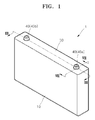
- FIG. 1 is a perspective view illustrating a secondary battery according to an embodiment of the present invention
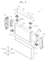
- FIG. 2 is an exploded perspective view of the secondary battery of FIG. 1
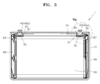
- Fig. 3 is a cross-sectional view of the secondary battery taken along line III-III of Fig. 1 .
- a secondary battery 1 may include a case 10, at least one electrode assembly 20 housed in the case 10, a cap plate 30, terminals 40, sealing members 50, collectors 60 coupling the terminals 40 and the electrode assemblies 20, insulation members 70, and retainers 80.
- the case 10, includes an opening OP configured to receive the at least one electrode assembly 20.
- the case 10 may have an approximate hexahedron shape, and the opening OP may be defined at an upper or top side of the case 10.
- the case 10, according to an embodiment may be formed of a metallic material.
- the case 10 may be an aluminum or an aluminum alloy.
- At least one electrode assembly 20 may be positioned in the case 10 through the opening OP.
- Each electrode assembly 20 may include a positive electrode plate, a negative electrode plate, and a separator therebetween.
- the negative electrode plate may include a coating portion having a foil such as copper foil coated with a negative electrode active material, and a non-coating portion of the foil not coated with the negative electrode active material.
- the positive electrode plate may include a coating portion having a foil such as aluminum foil coated with a positive electrode active material, and a non-coating portion of the foil not coated with the positive electrode active material.
- the negative electrode plate having the coating portion and the non-coating portion, the separator, and the positive electrode plate having the coating portion and the non-coating portion may be sequentially stacked and wound in the form of a jelly roll to form each of the electrode assemblies 20, according to an embodiment.
- the electrode assemblies 20 may be configured such that the non-coating portions of the negative electrode plates and the non-coating portions of the positive electrode plates are exposed in opposite directions, for example, in an x-axis direction and a negative x-axis (-x) direction, as indicated in FIG. 2 .
- the non-coating portions of the negative electrode plates exposed in the x-axis direction are the negative electrodes 21 of the electrode assembly 20
- the non-coating portions of the positive electrode plates are the positive electrodes 22 of the electrode assembly 20.
- the negative electrode plate, the separator, and the positive electrode plate are stacked and wound to form each of the electrode assemblies 20.
- the embodiments of the present invention are not limited thereto.
- a negative electrode plate, a separator, and a positive electrode plate may be sequentially stacked to form a stacking type electrode assembly, for example.
- the cap plate 30, is coupled to the case 10 at the opening OP.
- the cap plate 30, may be formed of a metallic material such as an aluminum or an aluminum alloy.
- the cap plate 30 may include an electrolyte inlet to inject electrolyte therethrough.
- electrolyte may be injected into the case 10 through the electrolyte inlet. After injecting electrolyte in these embodiments, the electrolyte inlet may be closed with a plug 31.
- the terminals 40 protrude upward through the cap plate 30.
- the terminals 40 include a first terminal 40a functioning as a negative electrode of the secondary battery 1 and a second terminal 40b functioning as a positive electrode of the secondary battery 1.
- the terminals 40 may penetrate respective holes 32 in the cap plate 30 to be exposed to an outer surface of the cap plate 30.
- the sealing members 50 may be positioned between the cap plate 30 and each of the terminals 40, and may be formed of an insulation material.
- the sealing members 50 may fill small gaps between the cap plate 30 and the terminals 40 and may insulate the cap plate 30 and the terminals 40 from each other.
- the electrolyte may leak through a small gap formed between the outside of the negative terminal 40a and the hole 32 of the cap plate 30 or the outside of the positive terminal 40b and the hole 32 of the cap plate 30.
- sealing members 50 may be positioned between the cap plate 30 and each of the terminals 40 to fill the small gaps and to seal the holes 32 from leaking.
- the sealing members 50 may electrically insulate the negative terminal 40a and/or the positive terminal 40b from the cap plate 30.
- the collectors 60 may electrically couple the terminals 40 to respective electrode assemblies 20.
- Each of the collectors 60 may include a first portion 61 substantially parallel to the cap plate 30 and a second portion 62 bent with respect to the first portion 61.
- the first portion 61 of each collector 60 may contact a lower surface of the respective terminal 40 for coupling to the terminals 40, and the second portion 62 of each collector 60 may contact the non-coating portions of the respective electrode assemblies 20 (in other words, the negative electrodes 21 and the positive electrodes 22 of each of the electrode assemblies 20) for coupling with these respective electrode assemblies 20.
- the second portion 62 of each of the collectors 60 may be electrically coupled to the negative electrode 21 and the positive electrode 22 of the electrode assemblies 20 by welding.
- the number of the electrode assemblies 20 is two.
- each of the collectors 60 may include two second portions 62 such that the second portion 62 may contact each of the negative electrode 21 and the positive electrode 22 of each of the electrode assemblies 20.
- the number of second portions 62 of the collectors 60 may vary according to the number of the electrode assemblies 20.
- the insulation members 70 are positioned between the electrode assemblies 20 and the collectors 60 to electrically insulate the electrode assemblies 20 and the collectors 60.
- the insulation members 70 may be placed under the collectors 60 to cover lower surfaces of the collectors 60.
- the insulation members 70 may cover lower surfaces of the first portion 61 of each collector 60.
- the insulation members 70 provide flow passages FP (as shown in FIG. 4 ) through which the electrolyte may flow.
- regions of the insulation members 70 may include protrusions 72 protruding downward, and gaps (flow passages FP) may form between the first portions 61 of the collectors 60 and the protrusions 72. Since the insulation members 70 include the flow passages FP, the electrolyte, which is liquid, may flow through the flow passages FP and participate in chemical reactions of the secondary battery 1, rather than stagnating in the small gaps that may form between the collectors 60 and the insulation members 70.
- the terminals 40 contacting the collectors 60 and electrically coupled to the cap plate 30 may short circuit.
- the insulation members 70 have flow passages FP for the electrolyte liquid to flow though, an external short circuit as described above may be prevented.
- the retainers 80 may electrically insulate the collectors 60 from the case 10 and may fix the positions of the collectors 60.
- the retainers 80 may be positioned between the collectors 60 and inner sides of the case 10 and may fix the positions of electrodes of the electrode assemblies 20, for example, the negative and positive electrodes 21 and 22 exposed at both sides of each of the electrode assemblies 20.
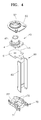
- FIG. 4 is an exploded top perspective view illustrating the the terminal 40, the collector 60, and the insulation member 70
- FIG. 5 is an exploded bottom perspective view of the terminal 40, the collector 60, and the insulation member 70 depicted in FIG. 4
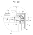
- FIG. 6A is an enlarged cross-sectional view illustrating portion Via of the secondary battery shown in FIG. 3
- FIG. 6B is a view illustrating another embodiment of the enlarged cross-sectional view of a modified portion Via illustrated in FIG. 6A .
- the first terminal 40a i.e., a negative electrode
- the second terminal 40b i.e., a positive electrode
- the structures of the sealing member 50, the terminal 40, the collector 60, and the insulation member 70 described below with reference to FIGS. 4 through 7 correspond to the structures of the sealing members 50, the first and second terminals 40a and 40b, the collectors 60, and the insulation members 70 located at each side of the secondary battery 1.
- the terminal 40 may include a flange 41 and a pillar 42 protruding up from the flange 41.
- the flange 41 extends approximately perpendicular to the pillar 42 to support the terminal 40 under the cap plate 30.
- At least one fixing protrusion 43 is positioned on a lower side of the flange 41.
- the fixing protrusion 43 may be inserted into a fixing hole 61 h (described below) of the collector 60.
- the terminal 40 and the collector 60 may be both mechanically and electrically coupled when the fixing protrusion 43 of the terminal 40 is coupled to the fixing hole 61 h of the collector 60.
- the sealing member 50 may be positioned on the pillar 42, according to an embodiment.
- the sealing member 50 may include a penetration hole 52, and the pillar 42 may be inserted through the penetration hole 52 of the sealing member 50 and the hole 32 (as shown in FIG. 2 ) of the cap plate 30, such that the pillar 42 may be exposed to an exterior of the cap plate 30.
- the collector 60 may include the first portion 61 substantially parallel to the cap plate 30 and the second portion 62 bent with respect to the first portion 61.
- the second portion 62 according to this embodiment may be bent in a direction substantially perpendicular to the first portion 61.
- the first portion 61 includes the fixing hole 61 h to which the fixing protrusion 43 of the terminal 40 may be coupled.
- the fixing protrusion 43 is through the fixing hole 61 h, bringing the first portion 61 into direct contact with the flange 41, and, thus, electrically coupling the first portion 61 to the flange 41.
- the second portion 62 may extend veritcally and may be welded to the electrode assemblies 20. According to an embodiment, the second portion 62 may be welded to the negative electrode 21 and/or the positive electrode 22 of each of the electrode assemblies 20.
- each collector 60 may electrically couple a respective terminal 40 with the electrode assemblies 20.
- the insulation member 70 in these embodiment extends over a lower surface of the collector 60.
- the insulation member 70 may extend over a lower surface of the first portion 61 of the collector 60.
- the insulation member 70 may include hook protrusions 75.
- the hook protrusions 75 may be coupled to catch jaws 45 on the terminal 40. In these embodiments, the hook protrusions 75 are coupled to the catch jaws 45 such that the insulation member 70 may fix the position of the collector 60.
- the insulation member 70 may electrically insulate the collector 60 from the electrode assemblies 20.
- the hook protrusions 75 on the insulation member 70 may be coupled to the catch jaws 45 on the terminal 40.
- the embodiments of the present invention are not limited thereto.
- the sealing member 50 may include grooves, and the hook protrusions 75 may be coupled to the grooves.
- the shapes of the hook protrusions 75 are not limited to those shown in FIG. 4 .
- the insulation member 70 may include a skirt 74 extending along a length of the second portion 62 of the collector 60.
- the skirt 74 may support a portion of the second portion 62 bent with respect to the first portion 61.
- the second portion 62 may be prevented from bending to a certain angle or greater than a second angle when an external force (for example, an external impact) is applied, or the first portion 61 may be prevented from fracturing due to the application of an excessive external force.
- a region of the insulation member 70 may protrude downward, forming a gap between the first portion 61 of the collector 60 and the insulation member 70.
- the gap formed between a region of the insulation member 70 including the protrusion 72 and the first portion 61 of the collector 60 may 72 function as a flow passage FP to allow flow of the electrolyte therethrough.
- the liquid electrolyte solution may be prevented from stagnating between the first portion 61 of the collector 60 and the insulation member 70 after being injected through the electrolyte inlet or when the secondary battery 1 is in operation, flowing, instead, through the flow passage FP, and, thus, preventing an external short circuit.
- the protrusion 72 of the insulation member 70 may be sloped in a certain direction, for example, in a direction of flow for the flow passage FP.
- the electrolyte flowing in the flow passage FP is assisted by gravity in its flow through the flow passage FP. Therefore, permeation of the electrolyte between the collector 60 and the insulation member 70 may be prevented more effectively. In other words, stagnation of the electrolyte between the collector 60 and the insulation member 70 may be prevented more effectively in an embodiment where the insulation member 70 is sloped at an oblique angle ⁇ .
- the protrusion 72 on the insulation member 70 may provide the flow passage FP described above, and may be useful to prevent movement of the electrode assemblies 20.
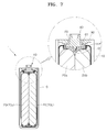
- FIG. 7 is a cross-sectional view and an enlarged view of the secondary battery taken along line VII-VII of Fig. 1 .
- the protrusion 72 may be positioned between the electrode assemblies 20 adjacent to each other, so as to prevent movement of the electrode assemblies 20.
- the protrusion 72 may be at a position corresponding to a caved region between a first electrode assembly 20a and a second electrode assembly 20b that are adjacent to each other and may contact upper surfaces of the first and second electrode assemblies 20a and 20b. In this embodiment, movement of the first and second electrode assemblies 20a and 20b in the case 10 may be prevented.
- electrical and mechanical coupling of elements of the secondary battery 1 may be stably maintained.
Landscapes
- Chemical & Material Sciences (AREA)
- Chemical Kinetics & Catalysis (AREA)
- Electrochemistry (AREA)
- General Chemical & Material Sciences (AREA)
- Engineering & Computer Science (AREA)
- Manufacturing & Machinery (AREA)
- Connection Of Batteries Or Terminals (AREA)
- Sealing Battery Cases Or Jackets (AREA)
Applications Claiming Priority (1)
| Application Number | Priority Date | Filing Date | Title |
|---|---|---|---|
| KR1020130139324A KR101720611B1 (ko) | 2013-11-15 | 2013-11-15 | 이차 전지 |
Publications (2)
| Publication Number | Publication Date |
|---|---|
| EP2874196A1 true EP2874196A1 (fr) | 2015-05-20 |
| EP2874196B1 EP2874196B1 (fr) | 2018-06-06 |
Family
ID=50933089
Family Applications (1)
| Application Number | Title | Priority Date | Filing Date |
|---|---|---|---|
| EP14172480.7A Active EP2874196B1 (fr) | 2013-11-15 | 2014-06-16 | Pieces de connexion et d'isolement à l'interieur d'une batterie secondaire |
Country Status (5)
| Country | Link |
|---|---|
| US (1) | US9666839B2 (fr) |
| EP (1) | EP2874196B1 (fr) |
| JP (1) | JP6445805B2 (fr) |
| KR (1) | KR101720611B1 (fr) |
| CN (1) | CN104659324B (fr) |
Cited By (1)
| Publication number | Priority date | Publication date | Assignee | Title |
|---|---|---|---|---|
| EP4571950A1 (fr) * | 2023-12-14 | 2025-06-18 | Samsung Sdi Co., Ltd. | Batterie secondaire |
Families Citing this family (11)
| Publication number | Priority date | Publication date | Assignee | Title |
|---|---|---|---|---|
| KR102102455B1 (ko) * | 2015-10-22 | 2020-04-20 | 주식회사 엘지화학 | 배터리 접속부와 이를 포함하는 배터리 팩 |
| JP6572736B2 (ja) * | 2015-10-30 | 2019-09-11 | 三洋電機株式会社 | 角形二次電池の製造方法 |
| KR102264700B1 (ko) * | 2016-07-25 | 2021-06-11 | 삼성에스디아이 주식회사 | 이차 전지 |
| CN106784586B (zh) * | 2016-12-14 | 2019-06-18 | 宁德时代新能源科技股份有限公司 | 二次电池 |
| KR102727851B1 (ko) | 2017-08-31 | 2024-11-11 | 삼성에스디아이 주식회사 | 이차 전지 |
| EP3451415B1 (fr) * | 2017-08-31 | 2020-03-25 | Samsung SDI Co., Ltd. | Batterie secondaire |
| JP7059548B2 (ja) * | 2017-09-27 | 2022-04-26 | 株式会社Gsユアサ | 蓄電素子 |
| CN110224099B (zh) * | 2018-03-01 | 2020-09-01 | 宁德时代新能源科技股份有限公司 | 二次电池及汽车 |
| KR102890541B1 (ko) * | 2019-05-14 | 2025-11-26 | 삼성에스디아이 주식회사 | 이차 전지 |
| KR20230100114A (ko) | 2021-12-28 | 2023-07-05 | 삼성에스디아이 주식회사 | 이차 전지 |
| JP7556904B2 (ja) * | 2022-03-09 | 2024-09-26 | プライムプラネットエナジー&ソリューションズ株式会社 | 電池 |
Citations (5)
| Publication number | Priority date | Publication date | Assignee | Title |
|---|---|---|---|---|
| EP2273587A1 (fr) * | 2009-07-09 | 2011-01-12 | SB LiMotive Co., Ltd. | Batterie rechargeable |
| EP2490282A1 (fr) * | 2011-02-18 | 2012-08-22 | SB LiMotive Co., Ltd. | Batterie secondaire |
| EP2551940A2 (fr) * | 2011-07-25 | 2013-01-30 | SB LiMotive Co., Ltd. | Batterie secondaire |
| US20130136976A1 (en) * | 2011-11-29 | 2013-05-30 | Gs Yuasa International Ltd. | Energy storage element and method for manufacturing the same |
| EP2660896A1 (fr) * | 2012-05-04 | 2013-11-06 | Samsung SDI Co., Ltd. | Batterie rechargeable |
Family Cites Families (13)
| Publication number | Priority date | Publication date | Assignee | Title |
|---|---|---|---|---|
| JP3017007B2 (ja) | 1994-01-25 | 2000-03-06 | 株式会社デンソー | スクロール型圧縮機 |
| KR100436714B1 (ko) * | 2002-10-29 | 2004-06-22 | 삼성에스디아이 주식회사 | 각형리튬이차전지 |
| KR100570625B1 (ko) * | 2004-07-28 | 2006-04-12 | 삼성에스디아이 주식회사 | 이차 전지 |
| JP5084205B2 (ja) | 2006-08-11 | 2012-11-28 | 三洋電機株式会社 | 非水電解質二次電池 |
| KR101318570B1 (ko) | 2007-04-27 | 2013-10-16 | 삼성에스디아이 주식회사 | 이차 전지 및 그 제조 방법 |
| KR100916418B1 (ko) * | 2007-12-14 | 2009-09-11 | 현대자동차주식회사 | 내구성이 향상된 자동차용 배터리 |
| WO2010141854A1 (fr) | 2009-06-05 | 2010-12-09 | K2 Energy Solutions, Inc. | Bloc de batteries au lithium-ion à refroidissement passif |
| US9178204B2 (en) * | 2009-12-07 | 2015-11-03 | Samsung Sdi Co., Ltd. | Rechargeable battery |
| KR101222309B1 (ko) * | 2010-12-29 | 2013-01-15 | 로베르트 보쉬 게엠베하 | 이차전지 |
| US9537121B2 (en) | 2011-03-18 | 2017-01-03 | Samsung Sdi Co., Ltd. | Secondary battery and secondary battery pack having a flexible collecting tab extending through a cap plate |
| US9136555B2 (en) * | 2011-05-02 | 2015-09-15 | Samsung Sdi Co., Ltd. | Rechargeable battery |
| US9236596B2 (en) * | 2011-06-30 | 2016-01-12 | Samsung Sdi Co., Ltd. | Rechargeable battery |
| US9083039B2 (en) * | 2012-03-28 | 2015-07-14 | Samsung Sdi Co., Ltd. | Rechargeable battery |
-
2013
- 2013-11-15 KR KR1020130139324A patent/KR101720611B1/ko active Active
-
2014
- 2014-05-02 US US14/269,033 patent/US9666839B2/en active Active
- 2014-06-16 EP EP14172480.7A patent/EP2874196B1/fr active Active
- 2014-08-05 JP JP2014159561A patent/JP6445805B2/ja active Active
- 2014-09-03 CN CN201410444579.0A patent/CN104659324B/zh active Active
Patent Citations (5)
| Publication number | Priority date | Publication date | Assignee | Title |
|---|---|---|---|---|
| EP2273587A1 (fr) * | 2009-07-09 | 2011-01-12 | SB LiMotive Co., Ltd. | Batterie rechargeable |
| EP2490282A1 (fr) * | 2011-02-18 | 2012-08-22 | SB LiMotive Co., Ltd. | Batterie secondaire |
| EP2551940A2 (fr) * | 2011-07-25 | 2013-01-30 | SB LiMotive Co., Ltd. | Batterie secondaire |
| US20130136976A1 (en) * | 2011-11-29 | 2013-05-30 | Gs Yuasa International Ltd. | Energy storage element and method for manufacturing the same |
| EP2660896A1 (fr) * | 2012-05-04 | 2013-11-06 | Samsung SDI Co., Ltd. | Batterie rechargeable |
Cited By (1)
| Publication number | Priority date | Publication date | Assignee | Title |
|---|---|---|---|---|
| EP4571950A1 (fr) * | 2023-12-14 | 2025-06-18 | Samsung Sdi Co., Ltd. | Batterie secondaire |
Also Published As
| Publication number | Publication date |
|---|---|
| KR101720611B1 (ko) | 2017-03-28 |
| EP2874196B1 (fr) | 2018-06-06 |
| CN104659324A (zh) | 2015-05-27 |
| KR20150056374A (ko) | 2015-05-26 |
| CN104659324B (zh) | 2019-11-12 |
| JP6445805B2 (ja) | 2018-12-26 |
| US20150140414A1 (en) | 2015-05-21 |
| JP2015097194A (ja) | 2015-05-21 |
| US9666839B2 (en) | 2017-05-30 |
Similar Documents
| Publication | Publication Date | Title |
|---|---|---|
| EP2874196B1 (fr) | Pieces de connexion et d'isolement à l'interieur d'une batterie secondaire | |
| CN109428045B (zh) | 二次电池及其组装方法 | |
| US10109838B2 (en) | Rechargeable battery and manufacturing method thereof | |
| US10673055B2 (en) | Secondary battery | |
| KR101222247B1 (ko) | 이차전지 | |
| KR101264495B1 (ko) | 이차 전지 및 이를 포함하는 전지 팩 | |
| KR101233470B1 (ko) | 이차 전지 | |
| US9136524B2 (en) | Secondary battery | |
| US8828596B2 (en) | Secondary battery including a lower terminal plate and an upper terminal plate | |
| EP2500964A2 (fr) | Batterie secondaire et bloc-batterie secondaire | |
| EP2958162A1 (fr) | Batterie secondaire | |
| KR20130004041A (ko) | 이차전지 | |
| KR102470495B1 (ko) | 이차전지 및 그 제조방법 | |
| CN107978699A (zh) | 二次电池 | |
| KR101222261B1 (ko) | 이차 전지 | |
| EP2876720B1 (fr) | Batterie secondaire | |
| US20200006742A1 (en) | Secondary battery | |
| US10211446B2 (en) | Rechargeable battery | |
| KR20250026230A (ko) | 이차 전지 | |
| CN101389185B (zh) | 保护电路板、电池组及其制造方法 | |
| KR102172843B1 (ko) | 이차 전지 | |
| KR20130005117A (ko) | 배터리 셀 및 이를 포함하는 배터리 팩 | |
| KR102211529B1 (ko) | 이차 전지 | |
| US8841021B2 (en) | Secondary battery | |
| KR20180035510A (ko) | 전극 조립체 및 이를 포함하는 이차 전지 |
Legal Events
| Date | Code | Title | Description |
|---|---|---|---|
| PUAI | Public reference made under article 153(3) epc to a published international application that has entered the european phase |
Free format text: ORIGINAL CODE: 0009012 |
|
| 17P | Request for examination filed |
Effective date: 20140616 |
|
| AK | Designated contracting states |
Kind code of ref document: A1 Designated state(s): AL AT BE BG CH CY CZ DE DK EE ES FI FR GB GR HR HU IE IS IT LI LT LU LV MC MK MT NL NO PL PT RO RS SE SI SK SM TR |
|
| AX | Request for extension of the european patent |
Extension state: BA ME |
|
| R17P | Request for examination filed (corrected) |
Effective date: 20151118 |
|
| RBV | Designated contracting states (corrected) |
Designated state(s): AL AT BE BG CH CY CZ DE DK EE ES FI FR GB GR HR HU IE IS IT LI LT LU LV MC MK MT NL NO PL PT RO RS SE SI SK SM TR |
|
| GRAP | Despatch of communication of intention to grant a patent |
Free format text: ORIGINAL CODE: EPIDOSNIGR1 |
|
| STAA | Information on the status of an ep patent application or granted ep patent |
Free format text: STATUS: GRANT OF PATENT IS INTENDED |
|
| INTG | Intention to grant announced |
Effective date: 20180123 |
|
| GRAS | Grant fee paid |
Free format text: ORIGINAL CODE: EPIDOSNIGR3 |
|
| GRAA | (expected) grant |
Free format text: ORIGINAL CODE: 0009210 |
|
| STAA | Information on the status of an ep patent application or granted ep patent |
Free format text: STATUS: THE PATENT HAS BEEN GRANTED |
|
| AK | Designated contracting states |
Kind code of ref document: B1 Designated state(s): AL AT BE BG CH CY CZ DE DK EE ES FI FR GB GR HR HU IE IS IT LI LT LU LV MC MK MT NL NO PL PT RO RS SE SI SK SM TR |
|
| REG | Reference to a national code |
Ref country code: GB Ref legal event code: FG4D |
|
| REG | Reference to a national code |
Ref country code: CH Ref legal event code: EP Ref country code: AT Ref legal event code: REF Ref document number: 1007017 Country of ref document: AT Kind code of ref document: T Effective date: 20180615 |
|
| REG | Reference to a national code |
Ref country code: IE Ref legal event code: FG4D Ref country code: FR Ref legal event code: PLFP Year of fee payment: 5 |
|
| REG | Reference to a national code |
Ref country code: DE Ref legal event code: R096 Ref document number: 602014026563 Country of ref document: DE |
|
| REG | Reference to a national code |
Ref country code: NL Ref legal event code: MP Effective date: 20180606 |
|
| REG | Reference to a national code |
Ref country code: LT Ref legal event code: MG4D |
|
| PG25 | Lapsed in a contracting state [announced via postgrant information from national office to epo] |
Ref country code: ES Free format text: LAPSE BECAUSE OF FAILURE TO SUBMIT A TRANSLATION OF THE DESCRIPTION OR TO PAY THE FEE WITHIN THE PRESCRIBED TIME-LIMIT Effective date: 20180606 Ref country code: SE Free format text: LAPSE BECAUSE OF FAILURE TO SUBMIT A TRANSLATION OF THE DESCRIPTION OR TO PAY THE FEE WITHIN THE PRESCRIBED TIME-LIMIT Effective date: 20180606 Ref country code: NO Free format text: LAPSE BECAUSE OF FAILURE TO SUBMIT A TRANSLATION OF THE DESCRIPTION OR TO PAY THE FEE WITHIN THE PRESCRIBED TIME-LIMIT Effective date: 20180906 Ref country code: BG Free format text: LAPSE BECAUSE OF FAILURE TO SUBMIT A TRANSLATION OF THE DESCRIPTION OR TO PAY THE FEE WITHIN THE PRESCRIBED TIME-LIMIT Effective date: 20180906 Ref country code: FI Free format text: LAPSE BECAUSE OF FAILURE TO SUBMIT A TRANSLATION OF THE DESCRIPTION OR TO PAY THE FEE WITHIN THE PRESCRIBED TIME-LIMIT Effective date: 20180606 Ref country code: LT Free format text: LAPSE BECAUSE OF FAILURE TO SUBMIT A TRANSLATION OF THE DESCRIPTION OR TO PAY THE FEE WITHIN THE PRESCRIBED TIME-LIMIT Effective date: 20180606 Ref country code: CY Free format text: LAPSE BECAUSE OF FAILURE TO SUBMIT A TRANSLATION OF THE DESCRIPTION OR TO PAY THE FEE WITHIN THE PRESCRIBED TIME-LIMIT Effective date: 20180606 |
|
| PG25 | Lapsed in a contracting state [announced via postgrant information from national office to epo] |
Ref country code: GR Free format text: LAPSE BECAUSE OF FAILURE TO SUBMIT A TRANSLATION OF THE DESCRIPTION OR TO PAY THE FEE WITHIN THE PRESCRIBED TIME-LIMIT Effective date: 20180907 Ref country code: RS Free format text: LAPSE BECAUSE OF FAILURE TO SUBMIT A TRANSLATION OF THE DESCRIPTION OR TO PAY THE FEE WITHIN THE PRESCRIBED TIME-LIMIT Effective date: 20180606 Ref country code: HR Free format text: LAPSE BECAUSE OF FAILURE TO SUBMIT A TRANSLATION OF THE DESCRIPTION OR TO PAY THE FEE WITHIN THE PRESCRIBED TIME-LIMIT Effective date: 20180606 Ref country code: LV Free format text: LAPSE BECAUSE OF FAILURE TO SUBMIT A TRANSLATION OF THE DESCRIPTION OR TO PAY THE FEE WITHIN THE PRESCRIBED TIME-LIMIT Effective date: 20180606 |
|
| REG | Reference to a national code |
Ref country code: AT Ref legal event code: MK05 Ref document number: 1007017 Country of ref document: AT Kind code of ref document: T Effective date: 20180606 |
|
| PG25 | Lapsed in a contracting state [announced via postgrant information from national office to epo] |
Ref country code: NL Free format text: LAPSE BECAUSE OF FAILURE TO SUBMIT A TRANSLATION OF THE DESCRIPTION OR TO PAY THE FEE WITHIN THE PRESCRIBED TIME-LIMIT Effective date: 20180606 |
|
| PG25 | Lapsed in a contracting state [announced via postgrant information from national office to epo] |
Ref country code: CZ Free format text: LAPSE BECAUSE OF FAILURE TO SUBMIT A TRANSLATION OF THE DESCRIPTION OR TO PAY THE FEE WITHIN THE PRESCRIBED TIME-LIMIT Effective date: 20180606 Ref country code: SK Free format text: LAPSE BECAUSE OF FAILURE TO SUBMIT A TRANSLATION OF THE DESCRIPTION OR TO PAY THE FEE WITHIN THE PRESCRIBED TIME-LIMIT Effective date: 20180606 Ref country code: RO Free format text: LAPSE BECAUSE OF FAILURE TO SUBMIT A TRANSLATION OF THE DESCRIPTION OR TO PAY THE FEE WITHIN THE PRESCRIBED TIME-LIMIT Effective date: 20180606 Ref country code: EE Free format text: LAPSE BECAUSE OF FAILURE TO SUBMIT A TRANSLATION OF THE DESCRIPTION OR TO PAY THE FEE WITHIN THE PRESCRIBED TIME-LIMIT Effective date: 20180606 Ref country code: IS Free format text: LAPSE BECAUSE OF FAILURE TO SUBMIT A TRANSLATION OF THE DESCRIPTION OR TO PAY THE FEE WITHIN THE PRESCRIBED TIME-LIMIT Effective date: 20181006 Ref country code: AT Free format text: LAPSE BECAUSE OF FAILURE TO SUBMIT A TRANSLATION OF THE DESCRIPTION OR TO PAY THE FEE WITHIN THE PRESCRIBED TIME-LIMIT Effective date: 20180606 Ref country code: PL Free format text: LAPSE BECAUSE OF FAILURE TO SUBMIT A TRANSLATION OF THE DESCRIPTION OR TO PAY THE FEE WITHIN THE PRESCRIBED TIME-LIMIT Effective date: 20180606 |
|
| REG | Reference to a national code |
Ref country code: CH Ref legal event code: PL |
|
| PG25 | Lapsed in a contracting state [announced via postgrant information from national office to epo] |
Ref country code: IT Free format text: LAPSE BECAUSE OF FAILURE TO SUBMIT A TRANSLATION OF THE DESCRIPTION OR TO PAY THE FEE WITHIN THE PRESCRIBED TIME-LIMIT Effective date: 20180606 Ref country code: SM Free format text: LAPSE BECAUSE OF FAILURE TO SUBMIT A TRANSLATION OF THE DESCRIPTION OR TO PAY THE FEE WITHIN THE PRESCRIBED TIME-LIMIT Effective date: 20180606 |
|
| REG | Reference to a national code |
Ref country code: BE Ref legal event code: MM Effective date: 20180630 |
|
| REG | Reference to a national code |
Ref country code: DE Ref legal event code: R097 Ref document number: 602014026563 Country of ref document: DE |
|
| REG | Reference to a national code |
Ref country code: IE Ref legal event code: MM4A |
|
| PG25 | Lapsed in a contracting state [announced via postgrant information from national office to epo] |
Ref country code: MC Free format text: LAPSE BECAUSE OF FAILURE TO SUBMIT A TRANSLATION OF THE DESCRIPTION OR TO PAY THE FEE WITHIN THE PRESCRIBED TIME-LIMIT Effective date: 20180606 Ref country code: LU Free format text: LAPSE BECAUSE OF NON-PAYMENT OF DUE FEES Effective date: 20180616 |
|
| PLBE | No opposition filed within time limit |
Free format text: ORIGINAL CODE: 0009261 |
|
| STAA | Information on the status of an ep patent application or granted ep patent |
Free format text: STATUS: NO OPPOSITION FILED WITHIN TIME LIMIT |
|
| PG25 | Lapsed in a contracting state [announced via postgrant information from national office to epo] |
Ref country code: IE Free format text: LAPSE BECAUSE OF NON-PAYMENT OF DUE FEES Effective date: 20180616 Ref country code: CH Free format text: LAPSE BECAUSE OF NON-PAYMENT OF DUE FEES Effective date: 20180630 Ref country code: LI Free format text: LAPSE BECAUSE OF NON-PAYMENT OF DUE FEES Effective date: 20180630 |
|
| 26N | No opposition filed |
Effective date: 20190307 |
|
| PG25 | Lapsed in a contracting state [announced via postgrant information from national office to epo] |
Ref country code: DK Free format text: LAPSE BECAUSE OF FAILURE TO SUBMIT A TRANSLATION OF THE DESCRIPTION OR TO PAY THE FEE WITHIN THE PRESCRIBED TIME-LIMIT Effective date: 20180606 Ref country code: SI Free format text: LAPSE BECAUSE OF FAILURE TO SUBMIT A TRANSLATION OF THE DESCRIPTION OR TO PAY THE FEE WITHIN THE PRESCRIBED TIME-LIMIT Effective date: 20180606 Ref country code: BE Free format text: LAPSE BECAUSE OF NON-PAYMENT OF DUE FEES Effective date: 20180630 |
|
| PG25 | Lapsed in a contracting state [announced via postgrant information from national office to epo] |
Ref country code: AL Free format text: LAPSE BECAUSE OF FAILURE TO SUBMIT A TRANSLATION OF THE DESCRIPTION OR TO PAY THE FEE WITHIN THE PRESCRIBED TIME-LIMIT Effective date: 20180606 |
|
| PG25 | Lapsed in a contracting state [announced via postgrant information from national office to epo] |
Ref country code: MT Free format text: LAPSE BECAUSE OF NON-PAYMENT OF DUE FEES Effective date: 20180616 |
|
| PG25 | Lapsed in a contracting state [announced via postgrant information from national office to epo] |
Ref country code: TR Free format text: LAPSE BECAUSE OF FAILURE TO SUBMIT A TRANSLATION OF THE DESCRIPTION OR TO PAY THE FEE WITHIN THE PRESCRIBED TIME-LIMIT Effective date: 20180606 |
|
| PG25 | Lapsed in a contracting state [announced via postgrant information from national office to epo] |
Ref country code: PT Free format text: LAPSE BECAUSE OF FAILURE TO SUBMIT A TRANSLATION OF THE DESCRIPTION OR TO PAY THE FEE WITHIN THE PRESCRIBED TIME-LIMIT Effective date: 20180606 |
|
| PG25 | Lapsed in a contracting state [announced via postgrant information from national office to epo] |
Ref country code: HU Free format text: LAPSE BECAUSE OF FAILURE TO SUBMIT A TRANSLATION OF THE DESCRIPTION OR TO PAY THE FEE WITHIN THE PRESCRIBED TIME-LIMIT; INVALID AB INITIO Effective date: 20140616 Ref country code: MK Free format text: LAPSE BECAUSE OF NON-PAYMENT OF DUE FEES Effective date: 20180606 |
|
| REG | Reference to a national code |
Ref country code: DE Ref legal event code: R079 Ref document number: 602014026563 Country of ref document: DE Free format text: PREVIOUS MAIN CLASS: H01M0002020000 Ipc: H01M0050100000 |
|
| P01 | Opt-out of the competence of the unified patent court (upc) registered |
Effective date: 20230528 |
|
| PGFP | Annual fee paid to national office [announced via postgrant information from national office to epo] |
Ref country code: DE Payment date: 20250604 Year of fee payment: 12 |
|
| PGFP | Annual fee paid to national office [announced via postgrant information from national office to epo] |
Ref country code: GB Payment date: 20250529 Year of fee payment: 12 |
|
| PGFP | Annual fee paid to national office [announced via postgrant information from national office to epo] |
Ref country code: FR Payment date: 20250610 Year of fee payment: 12 |