EP2874233A1 - Borne de connexion électrique de type à montage en surface, unité de module électronique et carte de circuit imprimé l'utilisant - Google Patents
Borne de connexion électrique de type à montage en surface, unité de module électronique et carte de circuit imprimé l'utilisant Download PDFInfo
- Publication number
- EP2874233A1 EP2874233A1 EP20140172367 EP14172367A EP2874233A1 EP 2874233 A1 EP2874233 A1 EP 2874233A1 EP 20140172367 EP20140172367 EP 20140172367 EP 14172367 A EP14172367 A EP 14172367A EP 2874233 A1 EP2874233 A1 EP 2874233A1
- Authority
- EP
- European Patent Office
- Prior art keywords
- fixed member
- movable member
- spring
- electric connecting
- fixed
- Prior art date
- Legal status (The legal status is an assumption and is not a legal conclusion. Google has not performed a legal analysis and makes no representation as to the accuracy of the status listed.)
- Granted
Links
Images









Classifications
-
- H—ELECTRICITY
- H01—ELECTRIC ELEMENTS
- H01R—ELECTRICALLY-CONDUCTIVE CONNECTIONS; STRUCTURAL ASSOCIATIONS OF A PLURALITY OF MUTUALLY-INSULATED ELECTRICAL CONNECTING ELEMENTS; COUPLING DEVICES; CURRENT COLLECTORS
- H01R13/00—Details of coupling devices of the kinds covered by groups H01R12/70 or H01R24/00 - H01R33/00
- H01R13/02—Contact members
- H01R13/22—Contacts for co-operating by abutting
- H01R13/24—Contacts for co-operating by abutting resilient; resiliently-mounted
- H01R13/2407—Contacts for co-operating by abutting resilient; resiliently-mounted characterized by the resilient means
- H01R13/2421—Contacts for co-operating by abutting resilient; resiliently-mounted characterized by the resilient means using coil springs
-
- H—ELECTRICITY
- H01—ELECTRIC ELEMENTS
- H01R—ELECTRICALLY-CONDUCTIVE CONNECTIONS; STRUCTURAL ASSOCIATIONS OF A PLURALITY OF MUTUALLY-INSULATED ELECTRICAL CONNECTING ELEMENTS; COUPLING DEVICES; CURRENT COLLECTORS
- H01R13/00—Details of coupling devices of the kinds covered by groups H01R12/70 or H01R24/00 - H01R33/00
- H01R13/02—Contact members
- H01R13/22—Contacts for co-operating by abutting
- H01R13/24—Contacts for co-operating by abutting resilient; resiliently-mounted
- H01R13/2407—Contacts for co-operating by abutting resilient; resiliently-mounted characterized by the resilient means
- H01R13/2428—Contacts for co-operating by abutting resilient; resiliently-mounted characterized by the resilient means using meander springs
-
- H—ELECTRICITY
- H01—ELECTRIC ELEMENTS
- H01R—ELECTRICALLY-CONDUCTIVE CONNECTIONS; STRUCTURAL ASSOCIATIONS OF A PLURALITY OF MUTUALLY-INSULATED ELECTRICAL CONNECTING ELEMENTS; COUPLING DEVICES; CURRENT COLLECTORS
- H01R4/00—Electrically-conductive connections between two or more conductive members in direct contact, i.e. touching one another; Means for effecting or maintaining such contact; Electrically-conductive connections having two or more spaced connecting locations for conductors and using contact members penetrating insulation
- H01R4/02—Soldered or welded connections
- H01R4/028—Soldered or welded connections comprising means for preventing flowing or wicking of solder or flux in parts not desired
-
- H—ELECTRICITY
- H01—ELECTRIC ELEMENTS
- H01R—ELECTRICALLY-CONDUCTIVE CONNECTIONS; STRUCTURAL ASSOCIATIONS OF A PLURALITY OF MUTUALLY-INSULATED ELECTRICAL CONNECTING ELEMENTS; COUPLING DEVICES; CURRENT COLLECTORS
- H01R12/00—Structural associations of a plurality of mutually-insulated electrical connecting elements, specially adapted for printed circuits, e.g. printed circuit boards [PCB], flat or ribbon cables, or like generally planar structures, e.g. terminal strips, terminal blocks; Coupling devices specially adapted for printed circuits, flat or ribbon cables, or like generally planar structures; Terminals specially adapted for contact with, or insertion into, printed circuits, flat or ribbon cables, or like generally planar structures
- H01R12/50—Fixed connections
- H01R12/51—Fixed connections for rigid printed circuits or like structures
- H01R12/55—Fixed connections for rigid printed circuits or like structures characterised by the terminals
- H01R12/57—Fixed connections for rigid printed circuits or like structures characterised by the terminals surface mounting terminals
-
- H—ELECTRICITY
- H01—ELECTRIC ELEMENTS
- H01R—ELECTRICALLY-CONDUCTIVE CONNECTIONS; STRUCTURAL ASSOCIATIONS OF A PLURALITY OF MUTUALLY-INSULATED ELECTRICAL CONNECTING ELEMENTS; COUPLING DEVICES; CURRENT COLLECTORS
- H01R12/00—Structural associations of a plurality of mutually-insulated electrical connecting elements, specially adapted for printed circuits, e.g. printed circuit boards [PCB], flat or ribbon cables, or like generally planar structures, e.g. terminal strips, terminal blocks; Coupling devices specially adapted for printed circuits, flat or ribbon cables, or like generally planar structures; Terminals specially adapted for contact with, or insertion into, printed circuits, flat or ribbon cables, or like generally planar structures
- H01R12/70—Coupling devices
- H01R12/71—Coupling devices for rigid printing circuits or like structures
- H01R12/712—Coupling devices for rigid printing circuits or like structures co-operating with the surface of the printed circuit or with a coupling device exclusively provided on the surface of the printed circuit
- H01R12/716—Coupling device provided on the PCB
- H01R12/718—Contact members provided on the PCB without an insulating housing
-
- H—ELECTRICITY
- H01—ELECTRIC ELEMENTS
- H01R—ELECTRICALLY-CONDUCTIVE CONNECTIONS; STRUCTURAL ASSOCIATIONS OF A PLURALITY OF MUTUALLY-INSULATED ELECTRICAL CONNECTING ELEMENTS; COUPLING DEVICES; CURRENT COLLECTORS
- H01R2201/00—Connectors or connections adapted for particular applications
- H01R2201/02—Connectors or connections adapted for particular applications for antennas
-
- H—ELECTRICITY
- H05—ELECTRIC TECHNIQUES NOT OTHERWISE PROVIDED FOR
- H05K—PRINTED CIRCUITS; CASINGS OR CONSTRUCTIONAL DETAILS OF ELECTRIC APPARATUS; MANUFACTURE OF ASSEMBLAGES OF ELECTRICAL COMPONENTS
- H05K2201/00—Indexing scheme relating to printed circuits covered by H05K1/00
- H05K2201/10—Details of components or other objects attached to or integrated in a printed circuit board
- H05K2201/10227—Other objects, e.g. metallic pieces
- H05K2201/1031—Surface mounted metallic connector elements
-
- H—ELECTRICITY
- H05—ELECTRIC TECHNIQUES NOT OTHERWISE PROVIDED FOR
- H05K—PRINTED CIRCUITS; CASINGS OR CONSTRUCTIONAL DETAILS OF ELECTRIC APPARATUS; MANUFACTURE OF ASSEMBLAGES OF ELECTRICAL COMPONENTS
- H05K3/00—Apparatus or processes for manufacturing printed circuits
- H05K3/30—Assembling printed circuits with electric components, e.g. with resistors
- H05K3/32—Assembling printed circuits with electric components, e.g. with resistors electrically connecting electric components or wires to printed circuits
- H05K3/34—Assembling printed circuits with electric components, e.g. with resistors electrically connecting electric components or wires to printed circuits by soldering
- H05K3/341—Surface mounted components
-
- Y—GENERAL TAGGING OF NEW TECHNOLOGICAL DEVELOPMENTS; GENERAL TAGGING OF CROSS-SECTIONAL TECHNOLOGIES SPANNING OVER SEVERAL SECTIONS OF THE IPC; TECHNICAL SUBJECTS COVERED BY FORMER USPC CROSS-REFERENCE ART COLLECTIONS [XRACs] AND DIGESTS
- Y02—TECHNOLOGIES OR APPLICATIONS FOR MITIGATION OR ADAPTATION AGAINST CLIMATE CHANGE
- Y02P—CLIMATE CHANGE MITIGATION TECHNOLOGIES IN THE PRODUCTION OR PROCESSING OF GOODS
- Y02P70/00—Climate change mitigation technologies in the production process for final industrial or consumer products
- Y02P70/50—Manufacturing or production processes characterised by the final manufactured product
Definitions
- Another object of the present invention is to provide a surface-mount type electric connecting terminal which has a lower height and a longer operating distance.
- the hook portion may comprise a hook protrusion formed by inwardly bending an edge of an opening of the fixed member; and a flange which extends outward in a horizontal direction along an edge of an opening of the movable member,wherein the thickness of the flange corresponds to the thickness of the movable member.
- the lower end surface of the fixed member may be slanted in an upward direction from the edge to the center for thereby having a recess.
- the non-soldering region may be formed in a circular shape in a central portion of the lower end surface of the fixed member.
- the height of the electric connecting terminal is 0.5mm to 3mm, and in case that the fixed member is a cylindrical shape, the diameter of the cross section in a horizontal direction is below 3mm.
- the fixed member and the movable member both are longer than the widths thereof and each comprise a wide width portion and a narrow width portion which is integrate at one side of the wide width portion and has smaller width than the wide width portion, and the spring is housed in each wide width portion.
- a surface-mount type electric connecting terminal comprising a box-shaped fixed member which is made from a metallic material; a box-shaped movable member which is slidably inserted in the fixed member and is made from a metallic material; and an electrical conductive flat spring which is accommodated in the fixed member and whose one end contacts with the bottom of the fixed member and the other end contacts with the bottom of the movable member for thereby allowing the movable member to elastically slide against the fixed member, wherein the movable member and the fixed member always keep electrically connected by the electrical conductive flat spring, and a hook portion is configured to prevent the movable member from being disengaged from the fixed member when elastic recovery force is transferred from the electrical conductive flat spring, and a flat surface is formed in the surface of the other end of the movable member for the sake of vacuum pickup, and the surface of the other end of the fixed member is configured to be reflow-soldered using solder cream.
- the electrical conductive flat spring comprises a pair of contact portions which contact with the bottom of the fixed member and the bottom of the movable member, and an elastic transformation portion which is disposed between the pair of the contact portions and is configured to connect the pair of the contact portions and is elastically transformed by external pressure.
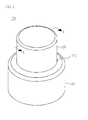
- FIG. 2 is a perspective view illustrating a surface-mount type electric connecting terminal according to an exemplary embodiment of the present invention
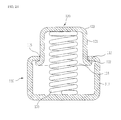
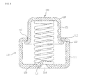
- FIG. 2A is a cross sectional view taken along line A-A in FIG. 2
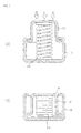
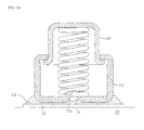
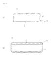
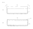
- FIGS. 3A and 3B are views illustrating a state before and after a movable member is pressed
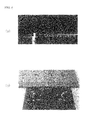
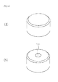
- FIGS. 4A and 4B are photos illustrating actual products of a surface-mount type electric connecting terminal.
- a surface-mount type electric connecting terminal 100 includes a fixed member 110 which is made from a metallic material, a movable member 120 which may slide against the fixed member 110 and is made from a metallic material, and a spring 130 which provides elastic force and elastic recovery force by which the movable member 120 may be inserted in the fixed member 110 and may slide elastically against the fixed member 110.
- the electric connecting terminal 100 is disposed between the opposing conductive objects and electrically connects the opposing conductive objects with elasticity.
- the opposing conductive objects may be identified as a printed circuit board, an antenna, etc.
- the fixed member 110 may be fixed to a printed circuit board by soldering.
- the antenna comes into contact with the movable member 120, the printed circuit board and the antenna may be electrically connected with elasticity.
- the size of the electric connecting terminal 100 is not limited, but a small size electric connecting terminal 100 with a height of about 0.5mm to 3 mm may be more efficiently used.
- the height of the electric connecting terminal 100 is same as or larger than the diameter of the fixed member 110, and the height of the electric connecting terminal 100 may be about 3 mm or less.
- a hook protrusion 112 is bent inward with a predetermined width and is formed along an edge of the opening 115 of the fixed member 110.
- a flange 122 of the movable member 120 contacts with and is caught by the hook protrusion 112 for thereby limiting the movement of the movable member 120.
- the total weight of the fixed member 110 is determined to be heavier than the total weight of the movable member 120 in order for the center of gravity to be positioned in the fixed member 110, thus minimizing any shaking during reflow soldering.
- the width of the flange 122 is not limited, and it will be enough if it is sized to the extent that the flange is not disengaged by the elastic recovery force of the spring 130 after it is caught by the hook protrusion 112 of the fixed member 110.
- the distance between anend surface of the flange 112 and the inner surface of the fixed member 110 is as larger as possible. Even if the movable member 120 is slanted while the object pressurizes the movable member 120, the flange 122 needs not to contact with the inner surface of the fixed member 110, thereby obtaining a smooth sliding of the movable member 120.
- the degree of the flatness of the upper surface means a degree where the vacuum pickup is possible. During the actual manufacturing process, it may be a little grooved in a downward direction or it may be bulged in an upward direction.
- the spring 130 is made from an elastic metallic material with good electrical conductivity and is housed in the fixed member, 110. One end of the spring 130 contacts with the bottom of the fixed member 110, and the other end contacts with the bottom of the movable member 120 for thereby providing elastic force and elastic recovery force to the movable member 120 which is movable in up and down directions.
- the spring 130 is manufactured in such a way to wind multiple times a metallic wire with electrical conductivity, with each turn being spaced apart to have elasticity in a vertical direction.
- the spring 130 may be coated with gold to have good electrical conductivity.
- an electrically conductive object such as an antenna, etc. presses and comes into contact with the upper surface of the surface-mounted electric connecting terminal 100. At this time, the movable member 120 moves downward by pressing force from the object. The movable member 120 moves receiving elastic force of the spring 130.
- the surface area of the lower surface of the fixed member 110 may increase by the recess 118, thus enhancing the soldering strength.
- a groove 114 in FIG. 5 may be formed at the center of the recess 118. Since the thickness and the size of the fixed member 110 is thin and small respectively, when the lower surface of the fixed member 110 is drawn in while the embossing 113 is being formed, the slanted surface 117 may be naturally formed, so the recess 118 may be provided.
- non-soldering region represents a region where is not soldered using typical solder cream.
- the springs 230 and 231 housed in the pairs of the wide width portions 211, 212 and 221, 222 are smaller than the diameters of the wide width portions 211, 212 and 221, 222, but larger than the diameters of the narrow width portions 213 and 223, so the springs 230 and 231 may not enter into the narrow width portions 213 and 223 after they disengage from the wide width portions 211, 212 and 221, 222.
- the electric connecting terminal 300 of this exemplary embodiment has a structure which is similar with the exemplary embodiment in FIG. 9 .
- the fixed member 310 and the movable member 320 include wide width portions 313 and 323 formed at the center, and pairs of narrow width portions 311, 312 and 321, 322 disposed at both sides thereof.
- one spring 330 is housed in the wide width portions 313 and 323 for thereby supplying elastic force to the movable member 320 from the center.
- the electric connecting terminal 400 comprises a fixed member 410 which is made from a metallic material, a movable member 420 which is engaged slidably against the fixed member 410 and is made from a metallic material, and a flat spring 430 which provides elastic force and elastic recovery force, so the movable member 420 may slide elastically against the fixed member 410.
- the flat spring 430 may have an important meaning for the following reasons.
- the electric resistance of the flat spring 430 having predetermined thickness and surface area electrically and mechanically connecting the fixed member 410 and the movable member 420 is smaller than the electric resistance of the coil spring on which thin metallic wire is wound, so it is possible to connect the fixed member 410 and the movable member 420 with small electric resistance.
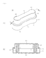
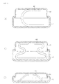
- FIGS. 17A to 17C are views illustrating a surface-mount type electric connecting terminal to which different flat springs are adapted.
- the electric connecting terminal 400 is supplied in a state where it is reel-taped on a carrier and is aligned on the conductive pattern of the printed circuit board by vacuum picking up the upper surface of the movable member 420 and is surface-mounted by reflow soldering.
- the size of the fixed member 410 is determined to be larger than the size of the movable member 420, and the width of the fixed member 410 is determined to be similar with the width of the conductive pattern, so the electric connecting terminal may be stably surface-mounted on the conductive pattern of the printed circuit board, and soldering strength is good.
- reflow soldering may be easily performed in a vacuum pickup process in such a way that top of the movable member is formed in a horizontally flat shape which enables a vacuum pickup work. Since the movable member is surely held by the fixed member, any disengagement of the movable member may be surely prevented in the middle of reflow soldering or even if there are plenty of movement in objects.
- the hardness of the material of the fixed member is lower than the hardness of the material of the movable member, so less scratch may occur on the surface of the movable member during the repeated compressions.
- the total weight of the fixed member may be greater than the total weight of the movable member in such a way to adjust the thickness of the member, so movement may be less during reflow soldering because the center of gravity leans toward the bottom of the electric connecting terminal.
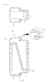
- the electronic module units 20 and 30 may be, for example, a speaker unit 20, a microphone unit 30, a motor unit, an antenna unit, a sensor unit, a display unit, or a camera unit, which is illustrated as an enlarged view of a circle of FIG. 19 .
- a pair of openings 22 is defined in a rear surface of the structure 21.
- An input pad 24 is disposed in each of the opening 22, and the elastic electric connecting terminal 100 is mounted on the conductive input pad 24 through soldering.
- the present embodiment is not limited to the number of openings22.
- the number of openings 22 may be variously changed according to the supplying of the power or signal.
- the elastic electric connecting terminal 100 constituting one portion of the electronic modules 20 and 30 may serve as a member for allowing the external object to electrically contact with the electric device of the electronic module units 20 and 30.
Landscapes
- Coupling Device And Connection With Printed Circuit (AREA)
- Structures For Mounting Electric Components On Printed Circuit Boards (AREA)
Applications Claiming Priority (3)
| Application Number | Priority Date | Filing Date | Title |
|---|---|---|---|
| KR20130138676 | 2013-11-14 | ||
| KR1020140043738A KR101437935B1 (ko) | 2013-11-14 | 2014-04-11 | 표면실장형 전기접속단자 |
| KR1020140046947A KR101517840B1 (ko) | 2013-11-14 | 2014-04-18 | 전기접속단자 |
Publications (2)
| Publication Number | Publication Date |
|---|---|
| EP2874233A1 true EP2874233A1 (fr) | 2015-05-20 |
| EP2874233B1 EP2874233B1 (fr) | 2017-01-25 |
Family
ID=50942134
Family Applications (1)
| Application Number | Title | Priority Date | Filing Date |
|---|---|---|---|
| EP14172367.6A Not-in-force EP2874233B1 (fr) | 2013-11-14 | 2014-06-13 | Borne de connexion électrique de type à montage en surface, unité de module électronique et carte de circuit imprimé l'utilisant |
Country Status (5)
| Country | Link |
|---|---|
| US (1) | US9306308B2 (fr) |
| EP (1) | EP2874233B1 (fr) |
| JP (1) | JP5869055B2 (fr) |
| CN (1) | CN104638413B (fr) |
| WO (1) | WO2015072642A1 (fr) |
Cited By (2)
| Publication number | Priority date | Publication date | Assignee | Title |
|---|---|---|---|---|
| FR3039932A1 (fr) * | 2015-08-03 | 2017-02-10 | Gilbert Ruffino | Systeme de connexion entre une batterie ou un groupe de batteries et appareil electrique destine a etre alimente par cette ou ces batteries |
| TWI718307B (zh) * | 2017-02-01 | 2021-02-11 | 日商Smk股份有限公司 | 連接件及連接器 |
Families Citing this family (34)
| Publication number | Priority date | Publication date | Assignee | Title |
|---|---|---|---|---|
| TWD174709S (zh) * | 2014-04-25 | 2016-04-01 | 卓英社有限公司 | 電氣連接接頭之部分 |
| CN104319508A (zh) * | 2014-08-29 | 2015-01-28 | 中航光电科技股份有限公司 | “8”字型弹性接触件及使用该接触件的电连接器 |
| US10437288B2 (en) | 2014-10-06 | 2019-10-08 | Fasetto, Inc. | Portable storage device with modular power and housing system |
| KR101793717B1 (ko) * | 2015-08-07 | 2017-11-03 | 조인셋 주식회사 | 전기접속단자 |
| USD781682S1 (en) * | 2015-10-06 | 2017-03-21 | Roly Llc | Magnetic two-hole pin |
| TWI604487B (zh) * | 2016-08-25 | 2017-11-01 | 緯創資通股份有限公司 | 電子裝置及其壓力感應件 |
| US11165182B2 (en) * | 2016-12-21 | 2021-11-02 | Amotech Co., Ltd. | Functional contactor |
| KR101944997B1 (ko) * | 2017-01-06 | 2019-02-01 | 조인셋 주식회사 | 금속패드 인터페이스 |
| CN110461658A (zh) | 2017-02-03 | 2019-11-15 | 法斯埃托股份有限公司 | 用于钥匙化设备中的数据存储的系统和方法 |
| CN106848795B (zh) * | 2017-02-09 | 2019-07-09 | 广东小天才科技有限公司 | 一种可穿戴设备的导电装置 |
| CN107046188B (zh) * | 2017-02-09 | 2019-03-08 | 广东小天才科技有限公司 | 一种智能穿戴设备的导电装置 |
| US10763630B2 (en) * | 2017-10-19 | 2020-09-01 | Fasetto, Inc. | Portable electronic device connection systems |
| DE102017124479A1 (de) * | 2017-10-19 | 2019-04-25 | Te Connectivity Germany Gmbh | Kontakteinrichtung und Kontaktsystem |
| DE102017218923A1 (de) * | 2017-10-24 | 2019-04-25 | Robert Bosch Gmbh | Elektrisches Überbrückungselement, elektrischer Energiespeicher und Vorrichtung |
| CN207424024U (zh) * | 2017-11-23 | 2018-05-29 | 周婷 | 电导探针的弹性体结构 |
| AU2018374384A1 (en) | 2017-12-01 | 2020-07-23 | Fasetto, Inc. | Systems and methods for improved data encryption |
| KR102183030B1 (ko) * | 2017-12-15 | 2020-11-25 | 조인셋 주식회사 | 전기접촉단자의 장착 구조 |
| CN108173012A (zh) * | 2018-02-02 | 2018-06-15 | 深圳市恒怡多精彩科技有限公司 | 能二次伸缩的pogopin |
| TWI655891B (zh) * | 2018-03-08 | 2019-04-01 | 綠點高新科技股份有限公司 | 電子模組及其製造方法及電子裝置的殼體及其製造方法 |
| MX2020010857A (es) | 2018-04-17 | 2021-01-15 | Fasetto Inc | Presentacion de dispositivo con comentarios en tiempo real. |
| EP4293816A3 (fr) * | 2018-06-12 | 2024-03-20 | KMW Inc. | Structure de connexion et filtre à cavité comprenant celle-ci |
| JP7240592B2 (ja) * | 2019-01-17 | 2023-03-16 | カシオ計算機株式会社 | 時計 |
| US11881643B2 (en) * | 2019-03-29 | 2024-01-23 | Sekisui Polymatech Co., Ltd. | Electrical connection member, and glass plate structure with terminal |
| JP2021039919A (ja) * | 2019-09-05 | 2021-03-11 | 株式会社東海理化電機製作所 | 導電ユニット |
| USD946533S1 (en) * | 2019-11-15 | 2022-03-22 | Cummins Ltd. | Pin element |
| WO2021241135A1 (fr) * | 2020-05-27 | 2021-12-02 | 日本精工株式会社 | Réducteur à vis sans fin et dispositif d'assistance électrique |
| USD951207S1 (en) * | 2020-06-19 | 2022-05-10 | DynaEnergetics Europe GmbH | Spring loaded circuit contact pin assembly |
| JP7568472B2 (ja) * | 2020-10-21 | 2024-10-16 | 株式会社ミツトヨ | パネルモジュールユニット |
| CN113015369B (zh) * | 2021-02-26 | 2022-06-03 | 川北医学院附属医院 | 一种医用手环的智能集成模块及其加工方法 |
| KR20230020308A (ko) * | 2021-08-03 | 2023-02-10 | 엘지이노텍 주식회사 | 카메라 모듈 |
| CN114284774A (zh) * | 2021-12-10 | 2022-04-05 | 苏州和林微纳科技股份有限公司 | 探针防爬锡结构 |
| CN114361839B (zh) * | 2022-01-19 | 2023-12-22 | 西北核技术研究所 | 一种自紧式镀金电接触 |
| GB2617372A (en) * | 2022-04-06 | 2023-10-11 | Asm Assembly Systems Singapore Pte Ltd | ESD tooling |
| CN117896916B (zh) * | 2024-03-15 | 2024-05-14 | 长春市高新东卓汽车电子有限公司 | 一种全自动电路板贴片设备及贴片工艺 |
Citations (8)
| Publication number | Priority date | Publication date | Assignee | Title |
|---|---|---|---|---|
| US5984697A (en) * | 1997-12-03 | 1999-11-16 | Qualcomm Incorporated | Ground clip apparatus for circuit boards |
| US6239393B1 (en) * | 1997-03-26 | 2001-05-29 | Kirk Acoustics A/S | Contact device and a tool for handling it |
| KR100332757B1 (ko) | 1998-01-15 | 2002-06-20 | 구자홍 | 냉장고용 디스펜서의 취출제어방법 |
| EP2099269A1 (fr) * | 2008-03-07 | 2009-09-09 | Joinset Co. Ltd. | Terminal de contact électrique élastique soudable |
| US20090298354A1 (en) * | 2008-05-29 | 2009-12-03 | Yokowo Co., Ltd. | Spring connector and connector |
| US20100295570A1 (en) * | 2009-05-22 | 2010-11-25 | Yin Te-Hung | Probe Connector |
| US20120217050A1 (en) * | 2009-11-16 | 2012-08-30 | Kitagawa Industries Co., Ltd. | Contact |
| US20130264098A1 (en) * | 2010-11-09 | 2013-10-10 | Kitagawa Industries Co., Ltd. | Contact and bonding structure of the contact |
Family Cites Families (15)
| Publication number | Priority date | Publication date | Assignee | Title |
|---|---|---|---|---|
| US5641315A (en) * | 1995-11-16 | 1997-06-24 | Everett Charles Technologies, Inc. | Telescoping spring probe |
| JPH10284158A (ja) * | 1997-03-31 | 1998-10-23 | Amp Japan Ltd | 基板用電気コネクタ |
| JP2002008761A (ja) * | 2000-06-23 | 2002-01-11 | Tyco Electronics Amp Kk | スプリングコンタクト |
| JP3923889B2 (ja) * | 2002-12-11 | 2007-06-06 | シチズン電子株式会社 | 表面実装型スプリングコネクタの製造方法 |
| TW563929U (en) * | 2002-12-24 | 2003-11-21 | Molex Inc | Press connection terminal |
| JP2004247170A (ja) * | 2003-02-13 | 2004-09-02 | Smk Corp | 押圧式スプリングコネクタ |
| KR200332757Y1 (ko) | 2003-08-05 | 2003-11-07 | 조인셋 주식회사 | 표면실장형 도전성 개스킷 |
| TWM251345U (en) * | 2003-09-30 | 2004-11-21 | Hon Hai Prec Ind Co Ltd | Electrical card connector |
| JP4194923B2 (ja) * | 2003-11-28 | 2008-12-10 | 小島プレス工業株式会社 | 接点装置 |
| DE102004033864A1 (de) * | 2004-07-13 | 2006-02-16 | Era-Contact Gmbh | Elektrischer Druckkontakt |
| US7955140B1 (en) * | 2010-03-08 | 2011-06-07 | Cheng Uei Precision Industry Co., Ltd. | Spring connector with a bottom cover and fabricating method thereof |
| CN201893476U (zh) * | 2010-11-30 | 2011-07-06 | 天津市柯文制模注塑有限公司 | 一种汽车线束连接器 |
| CN201889752U (zh) | 2010-11-30 | 2011-07-06 | 天津市柯文制模注塑有限公司 | 防水型接插件密封圈的装配治具 |
| JP2014096332A (ja) * | 2012-11-12 | 2014-05-22 | Kitagawa Ind Co Ltd | プローブピン |
| JP2014096325A (ja) * | 2012-11-12 | 2014-05-22 | Kitagawa Ind Co Ltd | コンタクト |
-
2014
- 2014-06-13 EP EP14172367.6A patent/EP2874233B1/fr not_active Not-in-force
- 2014-06-19 WO PCT/KR2014/005388 patent/WO2015072642A1/fr not_active Ceased
- 2014-06-25 JP JP2014130511A patent/JP5869055B2/ja not_active Expired - Fee Related
- 2014-06-26 US US14/315,673 patent/US9306308B2/en active Active
- 2014-09-16 CN CN201410471834.0A patent/CN104638413B/zh active Active
Patent Citations (8)
| Publication number | Priority date | Publication date | Assignee | Title |
|---|---|---|---|---|
| US6239393B1 (en) * | 1997-03-26 | 2001-05-29 | Kirk Acoustics A/S | Contact device and a tool for handling it |
| US5984697A (en) * | 1997-12-03 | 1999-11-16 | Qualcomm Incorporated | Ground clip apparatus for circuit boards |
| KR100332757B1 (ko) | 1998-01-15 | 2002-06-20 | 구자홍 | 냉장고용 디스펜서의 취출제어방법 |
| EP2099269A1 (fr) * | 2008-03-07 | 2009-09-09 | Joinset Co. Ltd. | Terminal de contact électrique élastique soudable |
| US20090298354A1 (en) * | 2008-05-29 | 2009-12-03 | Yokowo Co., Ltd. | Spring connector and connector |
| US20100295570A1 (en) * | 2009-05-22 | 2010-11-25 | Yin Te-Hung | Probe Connector |
| US20120217050A1 (en) * | 2009-11-16 | 2012-08-30 | Kitagawa Industries Co., Ltd. | Contact |
| US20130264098A1 (en) * | 2010-11-09 | 2013-10-10 | Kitagawa Industries Co., Ltd. | Contact and bonding structure of the contact |
Cited By (2)
| Publication number | Priority date | Publication date | Assignee | Title |
|---|---|---|---|---|
| FR3039932A1 (fr) * | 2015-08-03 | 2017-02-10 | Gilbert Ruffino | Systeme de connexion entre une batterie ou un groupe de batteries et appareil electrique destine a etre alimente par cette ou ces batteries |
| TWI718307B (zh) * | 2017-02-01 | 2021-02-11 | 日商Smk股份有限公司 | 連接件及連接器 |
Also Published As
| Publication number | Publication date |
|---|---|
| JP2015095454A (ja) | 2015-05-18 |
| CN104638413B (zh) | 2017-08-11 |
| EP2874233B1 (fr) | 2017-01-25 |
| US9306308B2 (en) | 2016-04-05 |
| JP5869055B2 (ja) | 2016-02-24 |
| CN104638413A (zh) | 2015-05-20 |
| US20150133000A1 (en) | 2015-05-14 |
| WO2015072642A1 (fr) | 2015-05-21 |
Similar Documents
| Publication | Publication Date | Title |
|---|---|---|
| US9306308B2 (en) | Surface-mount type electric connecting terminal, and electronic module unit and circuit board using the same | |
| US9350105B2 (en) | Surface-mount type electric connecting terminal, and electronic module unit and circuit board using the same | |
| EP2099269B1 (fr) | Terminal de contact électrique élastique soudable | |
| KR101517840B1 (ko) | 전기접속단자 | |
| CN106450879B (zh) | 电连接端子 | |
| US20120218727A1 (en) | Shield case for emi shielding | |
| KR100839893B1 (ko) | 솔더링 가능한 탄성 전기접촉단자 | |
| KR101129621B1 (ko) | 전자파 차폐 케이스용 금속 스트립 어셈블리, 이를 적용한 차폐 케이스 및 그 제조방법 | |
| US9240657B2 (en) | Socket connector with shielding structure | |
| KR101091884B1 (ko) | 전자파 차폐용 실드장치 | |
| KR101626030B1 (ko) | 탄성 전기접촉단자 | |
| KR101600510B1 (ko) | 리플로우 솔더링에 의한 표면실장이 가능한 포켓형 전기접촉단자 | |
| KR101591658B1 (ko) | 리플로우 솔더링에 의한 표면실장이 가능한 전기접촉단자 | |
| CN105896127B (zh) | 连接端子及包括连接端子的电路板模块 | |
| KR101688046B1 (ko) | 표면실장형 전기접속단자 | |
| KR101151689B1 (ko) | 전자파 차폐 케이스 고정용 클립 및 이를 적용한 전자파 차폐장치 | |
| US20100261359A1 (en) | Emi shield spring device | |
| KR20170041052A (ko) | 전기접촉단자 | |
| TWM473619U (zh) | 連接端子 | |
| JP2012129223A (ja) | 面実装部品の製造方法 |
Legal Events
| Date | Code | Title | Description |
|---|---|---|---|
| PUAI | Public reference made under article 153(3) epc to a published international application that has entered the european phase |
Free format text: ORIGINAL CODE: 0009012 |
|
| 17P | Request for examination filed |
Effective date: 20140613 |
|
| AK | Designated contracting states |
Kind code of ref document: A1 Designated state(s): AL AT BE BG CH CY CZ DE DK EE ES FI FR GB GR HR HU IE IS IT LI LT LU LV MC MK MT NL NO PL PT RO RS SE SI SK SM TR |
|
| AX | Request for extension of the european patent |
Extension state: BA ME |
|
| RIC1 | Information provided on ipc code assigned before grant |
Ipc: H01R 12/57 20110101ALN20160318BHEP Ipc: H01R 13/24 20060101ALI20160318BHEP Ipc: H05K 3/34 20060101ALN20160318BHEP Ipc: H01R 4/02 20060101AFI20160318BHEP Ipc: H01R 12/71 20110101ALN20160318BHEP Ipc: B23K 1/008 20060101ALI20160318BHEP |
|
| 17Q | First examination report despatched |
Effective date: 20160408 |
|
| RIC1 | Information provided on ipc code assigned before grant |
Ipc: B23K 1/008 20060101ALI20160623BHEP Ipc: H01R 4/02 20060101AFI20160623BHEP Ipc: H01R 13/24 20060101ALI20160623BHEP Ipc: H01R 12/57 20110101ALN20160623BHEP Ipc: H01R 12/71 20110101ALN20160623BHEP Ipc: H05K 3/34 20060101ALN20160623BHEP |
|
| GRAP | Despatch of communication of intention to grant a patent |
Free format text: ORIGINAL CODE: EPIDOSNIGR1 |
|
| INTG | Intention to grant announced |
Effective date: 20160816 |
|
| GRAS | Grant fee paid |
Free format text: ORIGINAL CODE: EPIDOSNIGR3 |
|
| STAA | Information on the status of an ep patent application or granted ep patent |
Free format text: STATUS: GRANT OF PATENT IS INTENDED |
|
| GRAA | (expected) grant |
Free format text: ORIGINAL CODE: 0009210 |
|
| STAA | Information on the status of an ep patent application or granted ep patent |
Free format text: STATUS: THE PATENT HAS BEEN GRANTED |
|
| AK | Designated contracting states |
Kind code of ref document: B1 Designated state(s): AL AT BE BG CH CY CZ DE DK EE ES FI FR GB GR HR HU IE IS IT LI LT LU LV MC MK MT NL NO PL PT RO RS SE SI SK SM TR |
|
| REG | Reference to a national code |
Ref country code: GB Ref legal event code: FG4D |
|
| REG | Reference to a national code |
Ref country code: CH Ref legal event code: EP |
|
| REG | Reference to a national code |
Ref country code: AT Ref legal event code: REF Ref document number: 864595 Country of ref document: AT Kind code of ref document: T Effective date: 20170215 |
|
| REG | Reference to a national code |
Ref country code: IE Ref legal event code: FG4D |
|
| REG | Reference to a national code |
Ref country code: DE Ref legal event code: R096 Ref document number: 602014006310 Country of ref document: DE |
|
| REG | Reference to a national code |
Ref country code: LT Ref legal event code: MG4D |
|
| REG | Reference to a national code |
Ref country code: NL Ref legal event code: MP Effective date: 20170125 |
|
| REG | Reference to a national code |
Ref country code: AT Ref legal event code: MK05 Ref document number: 864595 Country of ref document: AT Kind code of ref document: T Effective date: 20170125 |
|
| PG25 | Lapsed in a contracting state [announced via postgrant information from national office to epo] |
Ref country code: NL Free format text: LAPSE BECAUSE OF FAILURE TO SUBMIT A TRANSLATION OF THE DESCRIPTION OR TO PAY THE FEE WITHIN THE PRESCRIBED TIME-LIMIT Effective date: 20170125 |
|
| PG25 | Lapsed in a contracting state [announced via postgrant information from national office to epo] |
Ref country code: FI Free format text: LAPSE BECAUSE OF FAILURE TO SUBMIT A TRANSLATION OF THE DESCRIPTION OR TO PAY THE FEE WITHIN THE PRESCRIBED TIME-LIMIT Effective date: 20170125 Ref country code: GR Free format text: LAPSE BECAUSE OF FAILURE TO SUBMIT A TRANSLATION OF THE DESCRIPTION OR TO PAY THE FEE WITHIN THE PRESCRIBED TIME-LIMIT Effective date: 20170426 Ref country code: HR Free format text: LAPSE BECAUSE OF FAILURE TO SUBMIT A TRANSLATION OF THE DESCRIPTION OR TO PAY THE FEE WITHIN THE PRESCRIBED TIME-LIMIT Effective date: 20170125 Ref country code: NO Free format text: LAPSE BECAUSE OF FAILURE TO SUBMIT A TRANSLATION OF THE DESCRIPTION OR TO PAY THE FEE WITHIN THE PRESCRIBED TIME-LIMIT Effective date: 20170425 Ref country code: LT Free format text: LAPSE BECAUSE OF FAILURE TO SUBMIT A TRANSLATION OF THE DESCRIPTION OR TO PAY THE FEE WITHIN THE PRESCRIBED TIME-LIMIT Effective date: 20170125 Ref country code: IS Free format text: LAPSE BECAUSE OF FAILURE TO SUBMIT A TRANSLATION OF THE DESCRIPTION OR TO PAY THE FEE WITHIN THE PRESCRIBED TIME-LIMIT Effective date: 20170525 |
|
| PG25 | Lapsed in a contracting state [announced via postgrant information from national office to epo] |
Ref country code: RS Free format text: LAPSE BECAUSE OF FAILURE TO SUBMIT A TRANSLATION OF THE DESCRIPTION OR TO PAY THE FEE WITHIN THE PRESCRIBED TIME-LIMIT Effective date: 20170125 Ref country code: ES Free format text: LAPSE BECAUSE OF FAILURE TO SUBMIT A TRANSLATION OF THE DESCRIPTION OR TO PAY THE FEE WITHIN THE PRESCRIBED TIME-LIMIT Effective date: 20170125 Ref country code: PL Free format text: LAPSE BECAUSE OF FAILURE TO SUBMIT A TRANSLATION OF THE DESCRIPTION OR TO PAY THE FEE WITHIN THE PRESCRIBED TIME-LIMIT Effective date: 20170125 Ref country code: SE Free format text: LAPSE BECAUSE OF FAILURE TO SUBMIT A TRANSLATION OF THE DESCRIPTION OR TO PAY THE FEE WITHIN THE PRESCRIBED TIME-LIMIT Effective date: 20170125 Ref country code: AT Free format text: LAPSE BECAUSE OF FAILURE TO SUBMIT A TRANSLATION OF THE DESCRIPTION OR TO PAY THE FEE WITHIN THE PRESCRIBED TIME-LIMIT Effective date: 20170125 Ref country code: PT Free format text: LAPSE BECAUSE OF FAILURE TO SUBMIT A TRANSLATION OF THE DESCRIPTION OR TO PAY THE FEE WITHIN THE PRESCRIBED TIME-LIMIT Effective date: 20170525 Ref country code: BG Free format text: LAPSE BECAUSE OF FAILURE TO SUBMIT A TRANSLATION OF THE DESCRIPTION OR TO PAY THE FEE WITHIN THE PRESCRIBED TIME-LIMIT Effective date: 20170425 Ref country code: LV Free format text: LAPSE BECAUSE OF FAILURE TO SUBMIT A TRANSLATION OF THE DESCRIPTION OR TO PAY THE FEE WITHIN THE PRESCRIBED TIME-LIMIT Effective date: 20170125 |
|
| REG | Reference to a national code |
Ref country code: DE Ref legal event code: R097 Ref document number: 602014006310 Country of ref document: DE |
|
| PG25 | Lapsed in a contracting state [announced via postgrant information from national office to epo] |
Ref country code: IT Free format text: LAPSE BECAUSE OF FAILURE TO SUBMIT A TRANSLATION OF THE DESCRIPTION OR TO PAY THE FEE WITHIN THE PRESCRIBED TIME-LIMIT Effective date: 20170125 Ref country code: CZ Free format text: LAPSE BECAUSE OF FAILURE TO SUBMIT A TRANSLATION OF THE DESCRIPTION OR TO PAY THE FEE WITHIN THE PRESCRIBED TIME-LIMIT Effective date: 20170125 Ref country code: RO Free format text: LAPSE BECAUSE OF FAILURE TO SUBMIT A TRANSLATION OF THE DESCRIPTION OR TO PAY THE FEE WITHIN THE PRESCRIBED TIME-LIMIT Effective date: 20170125 Ref country code: SK Free format text: LAPSE BECAUSE OF FAILURE TO SUBMIT A TRANSLATION OF THE DESCRIPTION OR TO PAY THE FEE WITHIN THE PRESCRIBED TIME-LIMIT Effective date: 20170125 Ref country code: EE Free format text: LAPSE BECAUSE OF FAILURE TO SUBMIT A TRANSLATION OF THE DESCRIPTION OR TO PAY THE FEE WITHIN THE PRESCRIBED TIME-LIMIT Effective date: 20170125 |
|
| PG25 | Lapsed in a contracting state [announced via postgrant information from national office to epo] |
Ref country code: SM Free format text: LAPSE BECAUSE OF FAILURE TO SUBMIT A TRANSLATION OF THE DESCRIPTION OR TO PAY THE FEE WITHIN THE PRESCRIBED TIME-LIMIT Effective date: 20170125 Ref country code: DK Free format text: LAPSE BECAUSE OF FAILURE TO SUBMIT A TRANSLATION OF THE DESCRIPTION OR TO PAY THE FEE WITHIN THE PRESCRIBED TIME-LIMIT Effective date: 20170125 |
|
| PLBE | No opposition filed within time limit |
Free format text: ORIGINAL CODE: 0009261 |
|
| STAA | Information on the status of an ep patent application or granted ep patent |
Free format text: STATUS: NO OPPOSITION FILED WITHIN TIME LIMIT |
|
| 26N | No opposition filed |
Effective date: 20171026 |
|
| PG25 | Lapsed in a contracting state [announced via postgrant information from national office to epo] |
Ref country code: MC Free format text: LAPSE BECAUSE OF FAILURE TO SUBMIT A TRANSLATION OF THE DESCRIPTION OR TO PAY THE FEE WITHIN THE PRESCRIBED TIME-LIMIT Effective date: 20170125 |
|
| REG | Reference to a national code |
Ref country code: CH Ref legal event code: PL |
|
| PG25 | Lapsed in a contracting state [announced via postgrant information from national office to epo] |
Ref country code: SI Free format text: LAPSE BECAUSE OF FAILURE TO SUBMIT A TRANSLATION OF THE DESCRIPTION OR TO PAY THE FEE WITHIN THE PRESCRIBED TIME-LIMIT Effective date: 20170125 |
|
| REG | Reference to a national code |
Ref country code: IE Ref legal event code: MM4A |
|
| REG | Reference to a national code |
Ref country code: FR Ref legal event code: ST Effective date: 20180228 |
|
| PG25 | Lapsed in a contracting state [announced via postgrant information from national office to epo] |
Ref country code: CH Free format text: LAPSE BECAUSE OF NON-PAYMENT OF DUE FEES Effective date: 20170630 Ref country code: LU Free format text: LAPSE BECAUSE OF NON-PAYMENT OF DUE FEES Effective date: 20170613 Ref country code: LI Free format text: LAPSE BECAUSE OF NON-PAYMENT OF DUE FEES Effective date: 20170630 Ref country code: IE Free format text: LAPSE BECAUSE OF NON-PAYMENT OF DUE FEES Effective date: 20170613 |
|
| PG25 | Lapsed in a contracting state [announced via postgrant information from national office to epo] |
Ref country code: FR Free format text: LAPSE BECAUSE OF NON-PAYMENT OF DUE FEES Effective date: 20170630 |
|
| REG | Reference to a national code |
Ref country code: BE Ref legal event code: MM Effective date: 20170630 |
|
| PG25 | Lapsed in a contracting state [announced via postgrant information from national office to epo] |
Ref country code: BE Free format text: LAPSE BECAUSE OF NON-PAYMENT OF DUE FEES Effective date: 20170630 |
|
| PG25 | Lapsed in a contracting state [announced via postgrant information from national office to epo] |
Ref country code: MT Free format text: LAPSE BECAUSE OF NON-PAYMENT OF DUE FEES Effective date: 20170613 |
|
| GBPC | Gb: european patent ceased through non-payment of renewal fee |
Effective date: 20180613 |
|
| PG25 | Lapsed in a contracting state [announced via postgrant information from national office to epo] |
Ref country code: GB Free format text: LAPSE BECAUSE OF NON-PAYMENT OF DUE FEES Effective date: 20180613 |
|
| PG25 | Lapsed in a contracting state [announced via postgrant information from national office to epo] |
Ref country code: HU Free format text: LAPSE BECAUSE OF FAILURE TO SUBMIT A TRANSLATION OF THE DESCRIPTION OR TO PAY THE FEE WITHIN THE PRESCRIBED TIME-LIMIT; INVALID AB INITIO Effective date: 20140613 |
|
| PGFP | Annual fee paid to national office [announced via postgrant information from national office to epo] |
Ref country code: DE Payment date: 20190606 Year of fee payment: 6 |
|
| PG25 | Lapsed in a contracting state [announced via postgrant information from national office to epo] |
Ref country code: CY Free format text: LAPSE BECAUSE OF FAILURE TO SUBMIT A TRANSLATION OF THE DESCRIPTION OR TO PAY THE FEE WITHIN THE PRESCRIBED TIME-LIMIT Effective date: 20170125 |
|
| PG25 | Lapsed in a contracting state [announced via postgrant information from national office to epo] |
Ref country code: MK Free format text: LAPSE BECAUSE OF FAILURE TO SUBMIT A TRANSLATION OF THE DESCRIPTION OR TO PAY THE FEE WITHIN THE PRESCRIBED TIME-LIMIT Effective date: 20170125 |
|
| PG25 | Lapsed in a contracting state [announced via postgrant information from national office to epo] |
Ref country code: TR Free format text: LAPSE BECAUSE OF FAILURE TO SUBMIT A TRANSLATION OF THE DESCRIPTION OR TO PAY THE FEE WITHIN THE PRESCRIBED TIME-LIMIT Effective date: 20170125 |
|
| PG25 | Lapsed in a contracting state [announced via postgrant information from national office to epo] |
Ref country code: AL Free format text: LAPSE BECAUSE OF FAILURE TO SUBMIT A TRANSLATION OF THE DESCRIPTION OR TO PAY THE FEE WITHIN THE PRESCRIBED TIME-LIMIT Effective date: 20170125 |
|
| REG | Reference to a national code |
Ref country code: DE Ref legal event code: R119 Ref document number: 602014006310 Country of ref document: DE |
|
| PG25 | Lapsed in a contracting state [announced via postgrant information from national office to epo] |
Ref country code: DE Free format text: LAPSE BECAUSE OF NON-PAYMENT OF DUE FEES Effective date: 20210101 |