EP2874295A2 - Appareil et procédé pour détecter une carence de la phase de sortie d'un onduleur - Google Patents
Appareil et procédé pour détecter une carence de la phase de sortie d'un onduleur Download PDFInfo
- Publication number
- EP2874295A2 EP2874295A2 EP20140193371 EP14193371A EP2874295A2 EP 2874295 A2 EP2874295 A2 EP 2874295A2 EP 20140193371 EP20140193371 EP 20140193371 EP 14193371 A EP14193371 A EP 14193371A EP 2874295 A2 EP2874295 A2 EP 2874295A2
- Authority
- EP
- European Patent Office
- Prior art keywords
- phase
- phase deficiency
- output current
- deficiency
- inverter
- Prior art date
- Legal status (The legal status is an assumption and is not a legal conclusion. Google has not performed a legal analysis and makes no representation as to the accuracy of the status listed.)
- Granted
Links
Images


Classifications
-
- G—PHYSICS
- G01—MEASURING; TESTING
- G01R—MEASURING ELECTRIC VARIABLES; MEASURING MAGNETIC VARIABLES
- G01R31/00—Arrangements for testing electric properties; Arrangements for locating electric faults; Arrangements for electrical testing characterised by what is being tested not provided for elsewhere
- G01R31/40—Testing power supplies
- G01R31/42—AC power supplies
-
- G—PHYSICS
- G01—MEASURING; TESTING
- G01R—MEASURING ELECTRIC VARIABLES; MEASURING MAGNETIC VARIABLES
- G01R25/00—Arrangements for measuring phase angle between a voltage and a current or between voltages or currents
- G01R25/005—Circuits for comparing several input signals and for indicating the result of this comparison, e.g. equal, different, greater, smaller, or for passing one of the input signals as output signal
-
- H—ELECTRICITY
- H02—GENERATION; CONVERSION OR DISTRIBUTION OF ELECTRIC POWER
- H02M—APPARATUS FOR CONVERSION BETWEEN AC AND AC, BETWEEN AC AND DC, OR BETWEEN DC AND DC, AND FOR USE WITH MAINS OR SIMILAR POWER SUPPLY SYSTEMS; CONVERSION OF DC OR AC INPUT POWER INTO SURGE OUTPUT POWER; CONTROL OR REGULATION THEREOF
- H02M1/00—Details of apparatus for conversion
- H02M1/32—Means for protecting converters other than automatic disconnection
-
- G—PHYSICS
- G01—MEASURING; TESTING
- G01R—MEASURING ELECTRIC VARIABLES; MEASURING MAGNETIC VARIABLES
- G01R31/00—Arrangements for testing electric properties; Arrangements for locating electric faults; Arrangements for electrical testing characterised by what is being tested not provided for elsewhere
- G01R31/08—Locating faults in cables, transmission lines, or networks
-
- G—PHYSICS
- G01—MEASURING; TESTING
- G01R—MEASURING ELECTRIC VARIABLES; MEASURING MAGNETIC VARIABLES
- G01R31/00—Arrangements for testing electric properties; Arrangements for locating electric faults; Arrangements for electrical testing characterised by what is being tested not provided for elsewhere
- G01R31/40—Testing power supplies
-
- H—ELECTRICITY
- H02—GENERATION; CONVERSION OR DISTRIBUTION OF ELECTRIC POWER
- H02P—CONTROL OR REGULATION OF ELECTRIC MOTORS, ELECTRIC GENERATORS OR DYNAMO-ELECTRIC CONVERTERS; CONTROLLING TRANSFORMERS, REACTORS OR CHOKE COILS
- H02P29/00—Arrangements for regulating or controlling electric motors, appropriate for both AC and DC motors
- H02P29/02—Providing protection against overload without automatic interruption of supply
- H02P29/024—Detecting a fault condition, e.g. short circuit, locked rotor, open circuit or loss of load
- H02P29/0243—Detecting a fault condition, e.g. short circuit, locked rotor, open circuit or loss of load the fault being a broken phase
-
- G—PHYSICS
- G01—MEASURING; TESTING
- G01R—MEASURING ELECTRIC VARIABLES; MEASURING MAGNETIC VARIABLES
- G01R25/00—Arrangements for measuring phase angle between a voltage and a current or between voltages or currents
Definitions
- the present disclosure relates to an apparatus and a method for detecting phase deficiency in an inverter, and a method thereof.
- an inverter is a device which converts 3-phase direct current (DC) into alternating current (AC).
- FIG. 1 is a block diagram illustrating a general inverter, which drives a motor (2).
- the inverter (1) converts 3-phase AC power source into DC using a rectifying unit (10), then stores the converted DC in a DC link capacitor (20), and then converts it into AC again using a inverter unit (30) to provide the motor (2) with the converted AC. Additionally, the inverter (1) controls speed of the motor (2) by changing voltages and frequencies.
- phase deficiency which is caused by misconnection between the inverter (1) output end and the motor (2), or by malfunction of a switching device between the inverter (1) output end and the motor (2).
- phase deficiency occurs, an overcurrent exceeding rated current may be applied to the motor (2), causing a burning damage by degradation.
- Such a phase deficiency of an inverter may be determined by detecting an output current of the inverter.
- FIGs. 2a and 2b are block diagrams illustrating an inverter output current detection unit.
- FIG. 2a is illustrating a case in which a current transformer (CT) is used
- FIG. 2b is illustrating a case in which a leg-shunt resistor is used, respectively.
- CT current transformer
- the CT (41) is arranged on the output line of the inverter (1), and detects 3-phase output current of the inverter unit (30).
- the leg-shunt resistor (42) is arranged on the emitter end of the insulated gate bipolar transistor (IGBT) on each phase of the inverter unit (30), and detects output current of the inverter unit (30) when the current is flowing to the lower IGBT by switching operation status of the inverter unit (30).
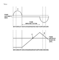
- FIG. 3 is an exemplary view illustrating output current detection restricted by switching operation status of an inverter.
- the inverter output current detection using a leg-shunt resistor takes a process which detects the active 2-phase current among the 3-phase current of the inverter, and then calculates the rest of one phase current.
- the following is a table showing calculations of current detection in the current detection using a leg-shunt resistor.
- Such a current detection using a leg-shunt resistor is commonly used for a small inverter of low-price type, because it is able to be performed at lower cost compared to the current detection using a CT.
- the technical challenge which the present disclosure intends to achieve is, to precisely detect a phase deficiency in output of an inverter when a current is detected by a leg-shunt resistor.
- a method for detecting phase deficiency of output current by receiving output current from a leg-shunt resistor in an inverter including a plurality of switching elements, the method comprising: deciding whether a sector of the output current is a sector where current detection is possible based on switching operation status of the switching element in the inverter; maintaining a phase deficiency variable when deciding the current detection in the sector of the output current to be impossible; adding a count to a phase deficiency variable to accumulate when deciding the current detection in the sector of the output current to be possible and deciding the output current to be within a phase deficiency band; and determining as phase deficiency when the phase deficiency variable is greater than a prescribed detection level.
- the method may further comprise determining a 3-phase output currents based on a 2-phase output currents received from the leg-shunt resistor.
- the method may further comprise subtracting a count from the phase deficiency variable to accumulate when deciding the current detection in the sector of the output current to be possible and deciding the output current to be outside of the phase deficiency band.
- the method may further comprise performing a predetermined protective action when determined as the phase deficiency.
- an apparatus for detecting phase deficiency comprising: an inverter including a plurality of switching elements; a leg-shunt resistor connected to a part of switching elements among the plurality of switching elements in the inverter; a first determining unit configured to determine a 3-phase output currents based on a 2-phase output currents determined by the leg-shunt resistor; and a second determining unit configured to: decide whether a sector of the output current is a sector where current detection is possible based on switching operation status of the switching element in the inverter, maintain a phase deficiency variable when deciding the current detection in the sector of the output current to be impossible, add a count to a phase deficiency variable to accumulate when deciding the current detection in the sector of the output current to be possible and deciding the output current to be within a phase deficiency band, and determine as phase deficiency when the phase deficiency variable
- the second determining unit may subtract a count from the phase deficiency variable to accumulate when deciding the current detection in the sector of the output current to be possible and deciding the output current to be outside of the phase deficiency band.
- the second determining unit may perform a predetermined protective action when determined as the phase deficiency.
- FIG. 4 is a block diagram illustrating an apparatus for detecting phase deficiency according to an exemplary embodiment of the present disclosure.
- the apparatus may receive an output current of an inverter from the leg-shunt resistor of FIG. 2b , and may determine whether there is phase deficiency in the output current.
- the apparatus for detecting phase deficiency may comprise an adjusting unit (43), an analog-digital converter (ADC) (44), an output current determining unit (45), and a phase deficiency determining unit (46).
- ADC analog-digital converter
- ADC analog-digital converter
- 45 output current determining unit
- 46 phase deficiency determining unit
- the adjusting unit (43) may perform low pass filtering (LPF) and scale adjusting for the output current from the leg-shut resistor.
- the ADC (44) may convert the output current into digital data.
- the output current determining unit (45) may calculate 1-phase current from 2-phase currents.
- the output current determining unit (45) may calculate the 1-phase current from the 2-phase currents using TABLE 1 in the above herein.
- the phase deficiency determining unit (46) may determine whether there is phase deficiency in each phase of the output current by receiving a 3-phase output current from the inverter.
- the phase deficiency determining unit (46) may determine that there is phase deficiency when each phase of the inverter output current is maintained for a predetermined period of time in a phase deficiency band.
- the output current is maintained in the predetermined phase deficiency band.
- the phase deficiency band means a section in which the current is constantly maintained when the phase deficiency occurs.
- the phase deficiency band may be predetermined.
- phase deficiency determining unit detects the phase deficiency
- FIG. 5 is a flow chart illustrating a conventional method for detecting phase deficiency.
- the phase deficiency determining unit (46) by receiving (S51) the inverter output current, determines (S52) whether an output current is outputted in the phase deficiency band in every inverter output current detection cycle.
- phase deficiency determining unit (46) adds a count to a phase deficiency variable (OPO_Cnt) to accumulate (S54). Such a process is repeated in every inverter output current detection cycle.
- phase deficiency determining unit (46) subtracts a count from a phase deficiency variable (OPO_Cnt) to prevent phase deficiency detection in normal operations of the inverter (S53).
- phase deficiency determining unit (46) determines that there is phase deficiency in the inverter, and performs a predetermined protective action (S56).
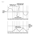
- FIG. 6 is an exemplary view illustrating a case of output current deficiency detection in a conventional phase deficiency detection method using a CT (41). In this case, there occurs phase deficiency in U-phase.
- phase deficiency variable (B) when the inverter output current (A) is within the phase deficiency band, a count is added to the phase deficiency variable (B). When the phase deficiency variable (B) is greater than the phase deficiency detection level (C), it is determined as phase deficiency.
- FIG. 7 is an exemplary view illustrating a case of output current deficiency detection in a conventional phase deficiency detection method using a leg-shunt resistor. In this case, there occurs phase deficiency in U-phase.
- the output current detection method using a leg-shunt resistor is to calculate the rest of one phase current after detecting the active 2-phase current among the 3-phase current of the inverter by switching sectors, a precise detection of the phase deficiency is not available.
- FIG. 8 is an experimental waveform diagram of conventional phase deficiency detection method using a leg-shunt resistor. It is apparent that the phase deficiency is not able to be detected even by the U-phase deficiency.
- the apparatus and the method according to an exemplary embodiment of the present disclosure may precisely detect the phase deficiency using a leg-shut resistor.
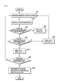
- FIG. 9 is a flow chart illustrating a method for detecting phase deficiency according to an exemplary embodiment of the present disclosure. The method may be performed by the apparatus for detecting phase deficiency as illustrated in FIG. 4 .
- the output current determining unit(45) may determine a 3-phase output current(S91), by receiving a 2-phase current among the inverter output current from the leg-shunt resistor.
- the phase deficiency determining unit (46) detects a sector based on switching operation status of the switching element in the inverter (S92). When it is decided that current detection of the relevant phase in the sector is impossible (S93), that is, when the current is of the phase calculated by the output current determining unit (45) through the current detected by the leg-shunt resistor, the phase deficiency determining unit (46) maintains the phase deficiency variable (OPP_Cnt) (S94). Only when it is decided that current detection is possible in the sector, the process may be moved to the next step.
- phase deficiency determining unit (46) ascertains whether the output current is within the phase deficiency band (S95). When it is ascertained that output current is within the phase deficiency band, the phase deficiency determining unit (46) adds a count to a phase deficiency variable (OPO_Cnt) to accumulate (S97), and repeats the same process in every output current detection cycle.
- OPO_Cnt phase deficiency variable
- phase deficiency determining unit (46) subtracts a count from a phase deficiency variable (OPO_Cnt) to prevent phase deficiency detection in normal operations of the inverter (S96).
- phase deficiency determining unit (46) determines it as an output current deficiency in the inverter, and performs a predetermined protective action (S99).
- FIG. 10 is an exemplary view illustrating a method for detecting phase deficiency according to an exemplary embodiment of the present disclosure.
- phase deficiency variable (F) the phase deficiency variable (F) in sectors 2 to 5 which the U-phase current is detected.
- the phase deficiency variable (F) is maintained without any change. Therefore, the precise detection of phase deficiency is available. That is to say, the phase deficiency is not able to be detected by the conventional detection method (E), whereas the phase deficiency is able to be detected according to an exemplary embodiment of the present disclosure (F).
- FIG. 11 is a signal waveform diagram illustrating a method for detecting phase deficiency according to an exemplary embodiment of the present disclosure.
- phase deficiency is able to be precisely detected so as to generate a trip signal initiating the protective action.
Landscapes
- Engineering & Computer Science (AREA)
- Power Engineering (AREA)
- Physics & Mathematics (AREA)
- General Physics & Mathematics (AREA)
- Inverter Devices (AREA)
Applications Claiming Priority (1)
| Application Number | Priority Date | Filing Date | Title |
|---|---|---|---|
| KR1020130139801A KR101516497B1 (ko) | 2013-11-18 | 2013-11-18 | 인버터의 출력결상 검출방법 |
Publications (3)
| Publication Number | Publication Date |
|---|---|
| EP2874295A2 true EP2874295A2 (fr) | 2015-05-20 |
| EP2874295A3 EP2874295A3 (fr) | 2015-06-10 |
| EP2874295B1 EP2874295B1 (fr) | 2019-04-10 |
Family
ID=51904775
Family Applications (1)
| Application Number | Title | Priority Date | Filing Date |
|---|---|---|---|
| EP14193371.3A Active EP2874295B1 (fr) | 2013-11-18 | 2014-11-17 | Appareil et procédé pour détecter une carence de la phase de sortie d'un onduleur |
Country Status (6)
| Country | Link |
|---|---|
| US (1) | US9448265B2 (fr) |
| EP (1) | EP2874295B1 (fr) |
| JP (1) | JP5981515B2 (fr) |
| KR (1) | KR101516497B1 (fr) |
| CN (1) | CN104655944B (fr) |
| ES (1) | ES2731218T3 (fr) |
Cited By (1)
| Publication number | Priority date | Publication date | Assignee | Title |
|---|---|---|---|---|
| EP3567710A1 (fr) * | 2018-05-09 | 2019-11-13 | LSIS Co., Ltd. | Dispositif de détection de perte de phase de sortie dans un inverseur |
Families Citing this family (6)
| Publication number | Priority date | Publication date | Assignee | Title |
|---|---|---|---|---|
| CN105467227A (zh) * | 2015-12-01 | 2016-04-06 | 长沙奥托自动化技术有限公司 | 一种变频器输出缺相的检测方法 |
| CN105606909B (zh) * | 2016-01-13 | 2018-04-17 | 厦门科灿信息技术有限公司 | 一种扇区遍历缺相检测方法 |
| CN106501717B (zh) * | 2016-09-26 | 2019-06-07 | Tcl空调器(中山)有限公司 | 电机的缺桥检测方法及装置 |
| CN110391642B (zh) * | 2018-04-23 | 2022-04-12 | 合肥美的电冰箱有限公司 | 用于压缩机缺相保护的方法和装置以及压缩机 |
| CN111030555B (zh) * | 2019-12-30 | 2022-03-29 | 上海拿森汽车电子有限公司 | 一种电机开路诊断方法和装置 |
| CN114325382B (zh) * | 2021-12-17 | 2023-08-22 | 珠海格力电器股份有限公司 | 一种三相交流电机缺相故障检测方法、系统及用电设备 |
Family Cites Families (19)
| Publication number | Priority date | Publication date | Assignee | Title |
|---|---|---|---|---|
| JPH05172443A (ja) | 1991-12-24 | 1993-07-09 | Mitsubishi Heavy Ind Ltd | 冷凍装置の電源欠相検出装置 |
| KR100397565B1 (ko) * | 2001-01-16 | 2003-09-13 | 엘지산전 주식회사 | 다기능 하이브리드 개폐기 |
| JP2003052191A (ja) | 2001-08-08 | 2003-02-21 | Sanyo Electric Co Ltd | モータの駆動装置及び駆動方法 |
| JP3674578B2 (ja) | 2001-11-29 | 2005-07-20 | 株式会社デンソー | 三相インバータの電流検出装置 |
| CN1548975A (zh) * | 2003-05-13 | 2004-11-24 | 乐金电子(天津)电器有限公司 | 电动机的相电流检测方法 |
| KR20070021573A (ko) | 2005-08-18 | 2007-02-23 | 삼성전자주식회사 | 모터 제어 장치, 그 제어방법 및 인버터부의 고장검출장치 |
| JP5230068B2 (ja) | 2006-01-13 | 2013-07-10 | オムロンオートモーティブエレクトロニクス株式会社 | インバータ装置 |
| KR100823723B1 (ko) * | 2006-10-10 | 2008-04-18 | 주식회사 포스콘 | 인버터구동 교류전동기의 고정자권선 결함 진단 장치 및방법 |
| JP5196923B2 (ja) | 2007-09-07 | 2013-05-15 | 株式会社東芝 | ランドリー機器 |
| JP5142917B2 (ja) * | 2008-09-26 | 2013-02-13 | オムロンオートモーティブエレクトロニクス株式会社 | 多相モータ駆動装置 |
| CN102004224B (zh) * | 2009-08-31 | 2012-12-12 | 比亚迪股份有限公司 | 一种三相电机缺相的检测系统及其检测方法 |
| KR101202949B1 (ko) * | 2011-06-29 | 2012-11-19 | 엘에스산전 주식회사 | 레그 션트 전류 검출 장치 |
| JP5703174B2 (ja) | 2011-09-05 | 2015-04-15 | 日立オートモティブシステムズ株式会社 | 電流検出器の故障診断方法及び、その装置 |
| CN103107689A (zh) * | 2011-11-11 | 2013-05-15 | 台达电子企业管理(上海)有限公司 | 一种级联型变频器、功率单元及其旁路模块 |
| JP2013106424A (ja) | 2011-11-14 | 2013-05-30 | Hitachi Ltd | モータ制御装置 |
| KR101321427B1 (ko) * | 2011-11-21 | 2013-10-28 | 한국전기연구원 | 결상 보호용 3상 컨버터 시스템 및 그 제어방법 |
| JP5482773B2 (ja) * | 2011-12-12 | 2014-05-07 | 京都電機器株式会社 | ターボ分子ポンプ用三相モータ駆動制御装置 |
| CN103376409B (zh) * | 2012-04-18 | 2015-05-13 | 珠海格力电器股份有限公司 | 三相电机缺相的检测方法和检测电路 |
| CN103023411A (zh) * | 2012-10-22 | 2013-04-03 | 东南大学 | 一种开绕组电机的缺相容错驱动系统 |
-
2013
- 2013-11-18 KR KR1020130139801A patent/KR101516497B1/ko active Active
-
2014
- 2014-11-12 US US14/539,658 patent/US9448265B2/en active Active
- 2014-11-17 EP EP14193371.3A patent/EP2874295B1/fr active Active
- 2014-11-17 CN CN201410819455.6A patent/CN104655944B/zh active Active
- 2014-11-17 ES ES14193371T patent/ES2731218T3/es active Active
- 2014-11-18 JP JP2014233595A patent/JP5981515B2/ja not_active Expired - Fee Related
Non-Patent Citations (1)
| Title |
|---|
| None |
Cited By (2)
| Publication number | Priority date | Publication date | Assignee | Title |
|---|---|---|---|---|
| EP3567710A1 (fr) * | 2018-05-09 | 2019-11-13 | LSIS Co., Ltd. | Dispositif de détection de perte de phase de sortie dans un inverseur |
| US10852325B2 (en) | 2018-05-09 | 2020-12-01 | Lsis Co., Ltd. | Device for detecting phase loss of output in inverter |
Also Published As
| Publication number | Publication date |
|---|---|
| JP2015100260A (ja) | 2015-05-28 |
| US20150138854A1 (en) | 2015-05-21 |
| CN104655944A (zh) | 2015-05-27 |
| US9448265B2 (en) | 2016-09-20 |
| EP2874295A3 (fr) | 2015-06-10 |
| CN104655944B (zh) | 2018-01-12 |
| EP2874295B1 (fr) | 2019-04-10 |
| ES2731218T3 (es) | 2019-11-14 |
| JP5981515B2 (ja) | 2016-08-31 |
| KR101516497B1 (ko) | 2015-05-04 |
Similar Documents
| Publication | Publication Date | Title |
|---|---|---|
| EP2874295A2 (fr) | Appareil et procédé pour détecter une carence de la phase de sortie d'un onduleur | |
| KR101993195B1 (ko) | 인버터의 지락 검출 방법 | |
| JP6402708B2 (ja) | インバータ装置 | |
| JP5689497B2 (ja) | Dcリンク部異常検出機能を備えたモータ駆動装置 | |
| JP6326083B2 (ja) | 電流センサのオフセット補正装置 | |
| JPWO2014049779A1 (ja) | 電力変換装置 | |
| EP2879289B1 (fr) | Appareil et procédé de commande d'onduleur | |
| JP2020058230A (ja) | 電流検出装置 | |
| KR102186763B1 (ko) | 과전류 보호 인버터 | |
| JP6543872B2 (ja) | 制御装置、制御方法及びプログラム | |
| KR102014185B1 (ko) | 인버터 피크전류 검출장치 | |
| EP3567710B1 (fr) | Dispositif de détection de perte de phase de sortie dans un inverseur | |
| CN104247243B (zh) | 整流装置及整流系统 | |
| US12038486B2 (en) | Inverter system capable of detecting output ground fault and output ground fault detection method using same | |
| JP2015115976A (ja) | ゲート駆動回路 | |
| EP3016258B1 (fr) | Appareil et procédé de protection d'un onduleur relié au réseau contre la survenue d'une faible tension du réseau | |
| CN113711479A (zh) | 功率转换装置 | |
| JP2011055590A (ja) | 電力変換装置及び電力変換装置の異常検出方法 | |
| JP2017121132A (ja) | 電力変換装置 |
Legal Events
| Date | Code | Title | Description |
|---|---|---|---|
| PUAL | Search report despatched |
Free format text: ORIGINAL CODE: 0009013 |
|
| PUAI | Public reference made under article 153(3) epc to a published international application that has entered the european phase |
Free format text: ORIGINAL CODE: 0009012 |
|
| 17P | Request for examination filed |
Effective date: 20141117 |
|
| AK | Designated contracting states |
Kind code of ref document: A2 Designated state(s): AL AT BE BG CH CY CZ DE DK EE ES FI FR GB GR HR HU IE IS IT LI LT LU LV MC MK MT NL NO PL PT RO RS SE SI SK SM TR |
|
| AX | Request for extension of the european patent |
Extension state: BA ME |
|
| AK | Designated contracting states |
Kind code of ref document: A3 Designated state(s): AL AT BE BG CH CY CZ DE DK EE ES FI FR GB GR HR HU IE IS IT LI LT LU LV MC MK MT NL NO PL PT RO RS SE SI SK SM TR |
|
| AX | Request for extension of the european patent |
Extension state: BA ME |
|
| RIC1 | Information provided on ipc code assigned before grant |
Ipc: H02M 1/32 20070101AFI20150507BHEP Ipc: H02P 29/02 20060101ALI20150507BHEP |
|
| R17P | Request for examination filed (corrected) |
Effective date: 20151209 |
|
| RBV | Designated contracting states (corrected) |
Designated state(s): AL AT BE BG CH CY CZ DE DK EE ES FI FR GB GR HR HU IE IS IT LI LT LU LV MC MK MT NL NO PL PT RO RS SE SI SK SM TR |
|
| GRAP | Despatch of communication of intention to grant a patent |
Free format text: ORIGINAL CODE: EPIDOSNIGR1 |
|
| STAA | Information on the status of an ep patent application or granted ep patent |
Free format text: STATUS: GRANT OF PATENT IS INTENDED |
|
| RIC1 | Information provided on ipc code assigned before grant |
Ipc: H02P 29/02 20060101ALI20180927BHEP Ipc: H02P 29/024 20160101ALI20180927BHEP Ipc: H02M 1/32 20070101AFI20180927BHEP |
|
| INTG | Intention to grant announced |
Effective date: 20181012 |
|
| RIC1 | Information provided on ipc code assigned before grant |
Ipc: H02P 29/02 20160101ALI20180927BHEP Ipc: H02M 1/32 20070101AFI20180927BHEP Ipc: H02P 29/024 20160101ALI20180927BHEP |
|
| GRAS | Grant fee paid |
Free format text: ORIGINAL CODE: EPIDOSNIGR3 |
|
| GRAA | (expected) grant |
Free format text: ORIGINAL CODE: 0009210 |
|
| STAA | Information on the status of an ep patent application or granted ep patent |
Free format text: STATUS: THE PATENT HAS BEEN GRANTED |
|
| AK | Designated contracting states |
Kind code of ref document: B1 Designated state(s): AL AT BE BG CH CY CZ DE DK EE ES FI FR GB GR HR HU IE IS IT LI LT LU LV MC MK MT NL NO PL PT RO RS SE SI SK SM TR |
|
| REG | Reference to a national code |
Ref country code: GB Ref legal event code: FG4D |
|
| REG | Reference to a national code |
Ref country code: CH Ref legal event code: EP Ref country code: AT Ref legal event code: REF Ref document number: 1120026 Country of ref document: AT Kind code of ref document: T Effective date: 20190415 |
|
| REG | Reference to a national code |
Ref country code: IE Ref legal event code: FG4D |
|
| REG | Reference to a national code |
Ref country code: DE Ref legal event code: R096 Ref document number: 602014044345 Country of ref document: DE |
|
| REG | Reference to a national code |
Ref country code: NL Ref legal event code: MP Effective date: 20190410 |
|
| REG | Reference to a national code |
Ref country code: LT Ref legal event code: MG4D |
|
| REG | Reference to a national code |
Ref country code: AT Ref legal event code: MK05 Ref document number: 1120026 Country of ref document: AT Kind code of ref document: T Effective date: 20190410 |
|
| PG25 | Lapsed in a contracting state [announced via postgrant information from national office to epo] |
Ref country code: NL Free format text: LAPSE BECAUSE OF FAILURE TO SUBMIT A TRANSLATION OF THE DESCRIPTION OR TO PAY THE FEE WITHIN THE PRESCRIBED TIME-LIMIT Effective date: 20190410 |
|
| PG25 | Lapsed in a contracting state [announced via postgrant information from national office to epo] |
Ref country code: FI Free format text: LAPSE BECAUSE OF FAILURE TO SUBMIT A TRANSLATION OF THE DESCRIPTION OR TO PAY THE FEE WITHIN THE PRESCRIBED TIME-LIMIT Effective date: 20190410 Ref country code: NO Free format text: LAPSE BECAUSE OF FAILURE TO SUBMIT A TRANSLATION OF THE DESCRIPTION OR TO PAY THE FEE WITHIN THE PRESCRIBED TIME-LIMIT Effective date: 20190710 Ref country code: SE Free format text: LAPSE BECAUSE OF FAILURE TO SUBMIT A TRANSLATION OF THE DESCRIPTION OR TO PAY THE FEE WITHIN THE PRESCRIBED TIME-LIMIT Effective date: 20190410 Ref country code: AL Free format text: LAPSE BECAUSE OF FAILURE TO SUBMIT A TRANSLATION OF THE DESCRIPTION OR TO PAY THE FEE WITHIN THE PRESCRIBED TIME-LIMIT Effective date: 20190410 Ref country code: LT Free format text: LAPSE BECAUSE OF FAILURE TO SUBMIT A TRANSLATION OF THE DESCRIPTION OR TO PAY THE FEE WITHIN THE PRESCRIBED TIME-LIMIT Effective date: 20190410 Ref country code: PT Free format text: LAPSE BECAUSE OF FAILURE TO SUBMIT A TRANSLATION OF THE DESCRIPTION OR TO PAY THE FEE WITHIN THE PRESCRIBED TIME-LIMIT Effective date: 20190910 Ref country code: HR Free format text: LAPSE BECAUSE OF FAILURE TO SUBMIT A TRANSLATION OF THE DESCRIPTION OR TO PAY THE FEE WITHIN THE PRESCRIBED TIME-LIMIT Effective date: 20190410 |
|
| PGFP | Annual fee paid to national office [announced via postgrant information from national office to epo] |
Ref country code: FR Payment date: 20190906 Year of fee payment: 6 |
|
| REG | Reference to a national code |
Ref country code: ES Ref legal event code: FG2A Ref document number: 2731218 Country of ref document: ES Kind code of ref document: T3 Effective date: 20191114 |
|
| PG25 | Lapsed in a contracting state [announced via postgrant information from national office to epo] |
Ref country code: PL Free format text: LAPSE BECAUSE OF FAILURE TO SUBMIT A TRANSLATION OF THE DESCRIPTION OR TO PAY THE FEE WITHIN THE PRESCRIBED TIME-LIMIT Effective date: 20190410 Ref country code: BG Free format text: LAPSE BECAUSE OF FAILURE TO SUBMIT A TRANSLATION OF THE DESCRIPTION OR TO PAY THE FEE WITHIN THE PRESCRIBED TIME-LIMIT Effective date: 20190710 Ref country code: GR Free format text: LAPSE BECAUSE OF FAILURE TO SUBMIT A TRANSLATION OF THE DESCRIPTION OR TO PAY THE FEE WITHIN THE PRESCRIBED TIME-LIMIT Effective date: 20190711 Ref country code: LV Free format text: LAPSE BECAUSE OF FAILURE TO SUBMIT A TRANSLATION OF THE DESCRIPTION OR TO PAY THE FEE WITHIN THE PRESCRIBED TIME-LIMIT Effective date: 20190410 Ref country code: RS Free format text: LAPSE BECAUSE OF FAILURE TO SUBMIT A TRANSLATION OF THE DESCRIPTION OR TO PAY THE FEE WITHIN THE PRESCRIBED TIME-LIMIT Effective date: 20190410 |
|
| PG25 | Lapsed in a contracting state [announced via postgrant information from national office to epo] |
Ref country code: AT Free format text: LAPSE BECAUSE OF FAILURE TO SUBMIT A TRANSLATION OF THE DESCRIPTION OR TO PAY THE FEE WITHIN THE PRESCRIBED TIME-LIMIT Effective date: 20190410 Ref country code: IS Free format text: LAPSE BECAUSE OF FAILURE TO SUBMIT A TRANSLATION OF THE DESCRIPTION OR TO PAY THE FEE WITHIN THE PRESCRIBED TIME-LIMIT Effective date: 20190810 |
|
| REG | Reference to a national code |
Ref country code: DE Ref legal event code: R097 Ref document number: 602014044345 Country of ref document: DE |
|
| PG25 | Lapsed in a contracting state [announced via postgrant information from national office to epo] |
Ref country code: CZ Free format text: LAPSE BECAUSE OF FAILURE TO SUBMIT A TRANSLATION OF THE DESCRIPTION OR TO PAY THE FEE WITHIN THE PRESCRIBED TIME-LIMIT Effective date: 20190410 Ref country code: RO Free format text: LAPSE BECAUSE OF FAILURE TO SUBMIT A TRANSLATION OF THE DESCRIPTION OR TO PAY THE FEE WITHIN THE PRESCRIBED TIME-LIMIT Effective date: 20190410 Ref country code: DK Free format text: LAPSE BECAUSE OF FAILURE TO SUBMIT A TRANSLATION OF THE DESCRIPTION OR TO PAY THE FEE WITHIN THE PRESCRIBED TIME-LIMIT Effective date: 20190410 Ref country code: EE Free format text: LAPSE BECAUSE OF FAILURE TO SUBMIT A TRANSLATION OF THE DESCRIPTION OR TO PAY THE FEE WITHIN THE PRESCRIBED TIME-LIMIT Effective date: 20190410 Ref country code: SK Free format text: LAPSE BECAUSE OF FAILURE TO SUBMIT A TRANSLATION OF THE DESCRIPTION OR TO PAY THE FEE WITHIN THE PRESCRIBED TIME-LIMIT Effective date: 20190410 |
|
| PLBE | No opposition filed within time limit |
Free format text: ORIGINAL CODE: 0009261 |
|
| STAA | Information on the status of an ep patent application or granted ep patent |
Free format text: STATUS: NO OPPOSITION FILED WITHIN TIME LIMIT |
|
| PG25 | Lapsed in a contracting state [announced via postgrant information from national office to epo] |
Ref country code: SM Free format text: LAPSE BECAUSE OF FAILURE TO SUBMIT A TRANSLATION OF THE DESCRIPTION OR TO PAY THE FEE WITHIN THE PRESCRIBED TIME-LIMIT Effective date: 20190410 |
|
| 26N | No opposition filed |
Effective date: 20200113 |
|
| PG25 | Lapsed in a contracting state [announced via postgrant information from national office to epo] |
Ref country code: TR Free format text: LAPSE BECAUSE OF FAILURE TO SUBMIT A TRANSLATION OF THE DESCRIPTION OR TO PAY THE FEE WITHIN THE PRESCRIBED TIME-LIMIT Effective date: 20190410 |
|
| PG25 | Lapsed in a contracting state [announced via postgrant information from national office to epo] |
Ref country code: SI Free format text: LAPSE BECAUSE OF FAILURE TO SUBMIT A TRANSLATION OF THE DESCRIPTION OR TO PAY THE FEE WITHIN THE PRESCRIBED TIME-LIMIT Effective date: 20190410 |
|
| REG | Reference to a national code |
Ref country code: CH Ref legal event code: PL |
|
| PG25 | Lapsed in a contracting state [announced via postgrant information from national office to epo] |
Ref country code: LI Free format text: LAPSE BECAUSE OF NON-PAYMENT OF DUE FEES Effective date: 20191130 Ref country code: LU Free format text: LAPSE BECAUSE OF NON-PAYMENT OF DUE FEES Effective date: 20191117 Ref country code: MC Free format text: LAPSE BECAUSE OF FAILURE TO SUBMIT A TRANSLATION OF THE DESCRIPTION OR TO PAY THE FEE WITHIN THE PRESCRIBED TIME-LIMIT Effective date: 20190410 Ref country code: CH Free format text: LAPSE BECAUSE OF NON-PAYMENT OF DUE FEES Effective date: 20191130 |
|
| REG | Reference to a national code |
Ref country code: BE Ref legal event code: MM Effective date: 20191130 |
|
| PG25 | Lapsed in a contracting state [announced via postgrant information from national office to epo] |
Ref country code: IE Free format text: LAPSE BECAUSE OF NON-PAYMENT OF DUE FEES Effective date: 20191117 |
|
| PG25 | Lapsed in a contracting state [announced via postgrant information from national office to epo] |
Ref country code: BE Free format text: LAPSE BECAUSE OF NON-PAYMENT OF DUE FEES Effective date: 20191130 |
|
| PG25 | Lapsed in a contracting state [announced via postgrant information from national office to epo] |
Ref country code: CY Free format text: LAPSE BECAUSE OF FAILURE TO SUBMIT A TRANSLATION OF THE DESCRIPTION OR TO PAY THE FEE WITHIN THE PRESCRIBED TIME-LIMIT Effective date: 20190410 |
|
| PG25 | Lapsed in a contracting state [announced via postgrant information from national office to epo] |
Ref country code: MT Free format text: LAPSE BECAUSE OF FAILURE TO SUBMIT A TRANSLATION OF THE DESCRIPTION OR TO PAY THE FEE WITHIN THE PRESCRIBED TIME-LIMIT Effective date: 20190410 Ref country code: HU Free format text: LAPSE BECAUSE OF FAILURE TO SUBMIT A TRANSLATION OF THE DESCRIPTION OR TO PAY THE FEE WITHIN THE PRESCRIBED TIME-LIMIT; INVALID AB INITIO Effective date: 20141117 |
|
| PG25 | Lapsed in a contracting state [announced via postgrant information from national office to epo] |
Ref country code: FR Free format text: LAPSE BECAUSE OF NON-PAYMENT OF DUE FEES Effective date: 20201130 |
|
| PG25 | Lapsed in a contracting state [announced via postgrant information from national office to epo] |
Ref country code: MK Free format text: LAPSE BECAUSE OF FAILURE TO SUBMIT A TRANSLATION OF THE DESCRIPTION OR TO PAY THE FEE WITHIN THE PRESCRIBED TIME-LIMIT Effective date: 20190410 |
|
| PGFP | Annual fee paid to national office [announced via postgrant information from national office to epo] |
Ref country code: GB Payment date: 20220905 Year of fee payment: 9 |
|
| PGFP | Annual fee paid to national office [announced via postgrant information from national office to epo] |
Ref country code: ES Payment date: 20221209 Year of fee payment: 9 |
|
| P01 | Opt-out of the competence of the unified patent court (upc) registered |
Effective date: 20230625 |
|
| GBPC | Gb: european patent ceased through non-payment of renewal fee |
Effective date: 20231117 |
|
| PG25 | Lapsed in a contracting state [announced via postgrant information from national office to epo] |
Ref country code: GB Free format text: LAPSE BECAUSE OF NON-PAYMENT OF DUE FEES Effective date: 20231117 |
|
| PG25 | Lapsed in a contracting state [announced via postgrant information from national office to epo] |
Ref country code: GB Free format text: LAPSE BECAUSE OF NON-PAYMENT OF DUE FEES Effective date: 20231117 |
|
| REG | Reference to a national code |
Ref country code: ES Ref legal event code: FD2A Effective date: 20250103 |
|
| PG25 | Lapsed in a contracting state [announced via postgrant information from national office to epo] |
Ref country code: ES Free format text: LAPSE BECAUSE OF NON-PAYMENT OF DUE FEES Effective date: 20231118 |
|
| PG25 | Lapsed in a contracting state [announced via postgrant information from national office to epo] |
Ref country code: ES Free format text: LAPSE BECAUSE OF NON-PAYMENT OF DUE FEES Effective date: 20231118 |
|
| PGFP | Annual fee paid to national office [announced via postgrant information from national office to epo] |
Ref country code: IT Payment date: 20250909 Year of fee payment: 12 |
|
| PGFP | Annual fee paid to national office [announced via postgrant information from national office to epo] |
Ref country code: DE Payment date: 20250908 Year of fee payment: 12 |