EP2874319A1 - Émetteur-récepteur et procédé d'annulation d'interférences - Google Patents
Émetteur-récepteur et procédé d'annulation d'interférences Download PDFInfo
- Publication number
- EP2874319A1 EP2874319A1 EP20130823477 EP13823477A EP2874319A1 EP 2874319 A1 EP2874319 A1 EP 2874319A1 EP 20130823477 EP20130823477 EP 20130823477 EP 13823477 A EP13823477 A EP 13823477A EP 2874319 A1 EP2874319 A1 EP 2874319A1
- Authority
- EP
- European Patent Office
- Prior art keywords
- signal
- cancellation
- path
- transceiver
- amplitude
- Prior art date
- Legal status (The legal status is an assumption and is not a legal conclusion. Google has not performed a legal analysis and makes no representation as to the accuracy of the status listed.)
- Granted
Links
Images


Classifications
-
- H—ELECTRICITY
- H04—ELECTRIC COMMUNICATION TECHNIQUE
- H04B—TRANSMISSION
- H04B1/00—Details of transmission systems, not covered by a single one of groups H04B3/00 - H04B13/00; Details of transmission systems not characterised by the medium used for transmission
- H04B1/38—Transceivers, i.e. devices in which transmitter and receiver form a structural unit and in which at least one part is used for functions of transmitting and receiving
- H04B1/40—Circuits
- H04B1/50—Circuits using different frequencies for the two directions of communication
- H04B1/52—Hybrid arrangements, i.e. arrangements for transition from single-path two-direction transmission to single-direction transmission on each of two paths or vice versa
- H04B1/525—Hybrid arrangements, i.e. arrangements for transition from single-path two-direction transmission to single-direction transmission on each of two paths or vice versa with means for reducing leakage of transmitter signal into the receiver
Definitions
- the present invention relates to the field of wireless communications technologies, and in particular, to a transceiver and an interference cancellation method.
- a base station is a basic device of a wireless network device.
- a base station device generally includes three parts: a base station control unit, a receiving device, and a transmitting device, where the receiving device and the transmitting device are collectively called a transceiver.
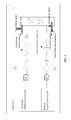
- FIG. 1 is a schematic diagram of basic composition of an existing transceiver with frequency division duplexing and different receiving and transmitting frequencies.
- a transmitting device generally includes the following units: a transmitter digital processing unit, a digital to analog converter (Digital to Analog Converter, DAC), an inverter, a filter, and a power amplifier (Power Amplifier, PA), and the like.
- a receiving device generally includes the following units: a receiver digital processing unit, an analog to digital converter (Analog to Digital Converter, ADC), an inverter, a filter, and a low noise amplifier (Low Noise Amplifier, LNA), and the like.
- a transmitting signal When a transmitting signal includes two or more frequencies, another may occur in an output signal because nonlinearity exists in a transmitting system, and if the another frequency falls right in a frequency range of a received signal, interference is directly superposed on the signal.
- interference is generally suppressed in a duplexer by using a transmitting filter and a receiving filter.
- the receiver encounters interference, as shown in FIG. 2 .
- FIG. 2 In the schematic diagram shown in FIG.
- a transmitting intermodulation signal (which is a triangle signal on either side of the transmitting signal in the schematic diagram of the figure) is generated due to a nonlinearity problem of the transmitting path.
- the transmitting intermodulation signal is transmitted to a receiving path by coupling of a duplexer, and the transmitting intermodulation signal falls on a received signal (as shown in figure, the received signal is on the left side of the transmitting signal, a rectangular signal with a lower amplitude is used to indicate the received signal, and the transmitting intermodulation signal shown as a triangle is mingled in the position of the received signal).
- the degree of suppression performed by the transmitting filter (which is shown as a TX filter above the duplexer in FIG. 2 ) of the duplexer affects a size and weight of the duplexer, thereby affecting an entire base station.
- Embodiments of the present invention provide a transceiver and an interference cancellation method, so that interference cancellation can be adaptively implemented by using a cancellation path, which is a path formed by an injection signal path and a cancellation module, thereby implementing miniaturization of a base station device under a condition of decreased interference.
- an embodiment of the present invention provides a transceiver, where the transceiver includes a transceiver digital processing unit, a transmitting path, a receiving path, an injection path, a duplexer, and a cancellation module, where the transceiver digital processing unit is configured to generate a transmitting signal, an injection signal, and a control signal, and obtain a received signal, where the control signal is used to adjust a transmission parameter of the cancellation module according to the received signal; the transmitting path is configured to output, to the duplexer, the transmitting signal generated by the transceiver digital processing unit; the receiving path is configured to input, to the transceiver digital processing unit, the received signal from the duplexer; the injection path is configured to output, to the cancellation module and the duplexer, the injection signal generated by the transceiver digital processing unit; and the cancellation module is configured to perform, according to the control signal, cancellation processing on the signal that is output to the duplexer by the transmitting path and the signal that is output by the injection path, to
- an embodiment of the present invention further provides an interference cancellation method, applied to a transceiver, where the method includes:
- a cancellation module is added to an existing transceiver, where the cancellation module is located between a transmitting path and a receiving path and performs automatic adjustment on a cancellation effect of the cancellation module according to an injection signal received through the receiving path; thereby not only implementing adaptive cancellation of transmitting intermodulation interference signal, but also avoiding increasing size of a duplexer and obviously increasing size and weight of the entire transceiver.
- interference cancellation of a transmitting intermodulation signal is implemented by using a cancellation module; and at the same time, it is taken into consideration that a duplexer constantly changes with a change of an ambient temperature in actual system application. Therefore, in the solution of the present invention, interference cancellation modeling and system cancellation effect determining are performed by using an injection signal so as to implement adaptive interference cancellation of a cancellation module.
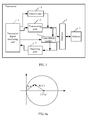
- FIG. 3 is a schematic diagram of specific composition of a transceiver according to an embodiment of the present invention.
- the transceiver includes a transceiver digital processing unit 1, a transmitting path 2, a receiving path 5, an injection path 6, a duplexer 3, and a cancellation module 7.
- the transceiver may further include an antenna 4 that is connected to the duplexer 3.
- the transceiver digital processing unit 1 is configured to generate a transmitting signal, an injection signal, and a control signal, and obtain a received signal, where the control signal is used to adjust a transmission parameter of the cancellation module 7 according to the received signal.
- a frequency band of the injection signal includes a frequency band of the received signal, and the injection signal may specifically be a multi-tone signal or a random signal.
- the transmitting path 2 is configured to output, to the duplexer 3, the transmitting signal generated by the transceiver digital processing unit 1.
- the receiving path 5 is configured to input, to the transceiver digital processing unit 1, the received signal from the duplexer 3.
- the injection path 6 is configured to output, to the cancellation module 7 and the duplexer 3, the injection signal generated by the transceiver digital processing unit 1.
- the cancellation module 7 is configured to perform, according to the control signal, cancellation processing on the signal that is output to the duplexer 3 by the transmitting path 2 and the signal that is output by the injection path 6, to obtain a cancellation signal, and input the cancellation signal to the receiving path 5.
- the signal input to the duplexer 3 and the cancellation module 7 further includes transmitting intermodulation interference, which is no longer described one by one subsequently.
- the cancellation module 7 includes a filter and an amplitude and phase modulator, where the filter is configured to perform filtering on a signal that is input to the cancellation module 7, to obtain a signal within a frequency band of the transmitting intermodulation interference; and the amplitude and phase modulator is configured to perform, according to control of the control signal, cancellation processing on a signal filtered by the filter, to obtain the cancellation signal, so that the cancellation signal and a transmitting intermodulation interference signal that is coupled to the receiving path 5 by the duplexer 3 have a same phase but opposite amplitudes.
- the transceiver may further include a switch submodule, where the switch submodule is configured to: according to control of the transceiver digital processing unit 1, connect the cancellation module 7 between the transmitting path 2 and the receiving path 5, or disconnect the cancellation module 7 from the transmitting path 2 and the receiving path 5.
- the switch submodule may be a switch at a connection side of the cancellation module 7 and the transmitting path 2 or may be a switch at a connection side of the cancellation module 7 and the receiving path 5.
- the cancellation module 7 in the embodiment of the present invention may be an analog cancellation module or may be a digital cancellation module.
- the cancellation module 6 has a filter, that is, a filter is added to the transceiver, this type of filter does not need to ensure that a transmitting signal is not attenuated while performing suppression on an interference signal, as a transmitting filter of the duplexer 3 does. Therefore, the filter in the cancellation module 7 may be obtained by combining simpler filters as long as the filter can obtain a signal of a specific frequency band by filtering; and it is not required to take into consideration an impact on whether a signal of another frequency band is reserved. To sum up, adding such a filter does not obviously increases weight and a scale of the transceiver.
- the transceiver digital processing unit 1 may further include a control signal generating module, which is configured to generate, after the cancellation module 7 is connected, the control signal according to a signal that is output by the receiving path 5, and adaptively adjust the control signal according to a value of the signal that is output by the receiving path 5.
- a control signal generating module which is configured to generate, after the cancellation module 7 is connected, the control signal according to a signal that is output by the receiving path 5, and adaptively adjust the control signal according to a value of the signal that is output by the receiving path 5.
- adaptive adjustment may be performed on the amplitude and phase modulator included in the cancellation module 7, so as to implement adaptive adjustment on the cancellation signal that is output by the cancellation module 7.
- the amplitude and phase modulator may be configured to perform, according to the control of the control signal, cancellation processing on a signal of the cancellation module 7 to obtain the cancellation signal.
- the control signal generating module is configured to generate an amplitude modulation signal and a phase modulation signal. Therefore, the control signal includes the amplitude modulation signal and the phase modulation signal, so that, during specific adjustment, adjustment may be separately performed on amplitude and a phase of the output cancellation signal.
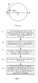
- the amplitude modulation signal is used to adjust an amplitude of the amplitude and phase modulator when phase adjustment of the amplitude and phase modulator is fixed, so that a polar coordinate vector of B/A is located on a circle that is centered at (1, 0°) and with a radius of 1.
- h dup ( t )+ h canceller ( t ) 0
- a signal that is coupled to the receiving path 5 by using the cancellation module 7 (transfer function) and the transmitting intermodulation interference signal coupled to the receiving path 5 by the duplexer 3 have a same phase but opposite amplitude.
- the transmitting intermodulation signal after being coupled to the receiving path 5 by using the duplexer 3, may be canceled by the signal coupled to the receiving path 5 by using the cancellation module 7, that is, relatively excellent interference suppression can be implemented.
- an amplitude may be adjusted first so that
- 0, that is, the polar coordinate vector of B/A is located on the circle that is centered at (1, 0°) and with a radius of 1.
- FIG. 4a and FIG. 4b show a position of B/A in the polar coordinates before the adjustment.
- FIG. 5a and FIG. 5b show a position of B/A in the polar coordinates after the amplitude adjustment.
- a switch submodule of the cancellation module may be used to assist the adjustment.
- the cancellation module is first disconnected, an injection signal is injected to obtain a signal A, and then, after the cancellation module is connected, a same multi-tone signal is injected to obtain a signal B, so that B/A is acquired.
- Amplitude adjustment is performed on an amplitude adjustment apparatus of the cancellation module according to a position of B/A in the polar coordinates; and then phase adjustment is performed on a phase adjustment apparatus of the cancellation module.
- a cancellation module may usually stay in a disabled state (that is, be disconnected from a transmitting path or a receiving path) and be enabled when required.
- the transceiver digital processing unit 1 is further configured to periodically perform, when the cancellation module 7 is connected between the transmitting path 2 and the receiving path 5, adjustment on the cancellation module 7 by using the control signal, to generate the cancellation signal.
- an effect of interference cancellation can be adaptively detected; and further, an adjustment direction of an interference cancellation module can be determined by detecting an amplitude and phase feature of a signal obtained by receiving.
- FIG.7 shows an interference cancellation method according to an embodiment of the present embodiment, where the method is applied to a transceiver and includes the following steps:
- a transceiver digital processing unit of the transceiver generates a transmitting signal, where the transmitting signal is output to a duplexer of the transceiver by a transmitting path of the transceiver.
- the transceiver digital processing unit generates an injection signal, where the injection signal is output to the duplexer by an injection path of the transceiver.
- a frequency band of the injection signal includes a frequency band of a received signal, for example, the injection signal includes a multi-tone signal.
- the transceiver digital processing unit receives a received signal from the duplexer through a receiving path of the transceiver.
- the signal includes transmitting intermodulation interference coupled by using a cancellation module and the duplexer that are parallel, also includes a normal received signal, and further includes an injection signal coupled by using the cancellation module and the duplexer that are parallel.
- both the coupled transmitting intermodulation interference and injection signal approach zero.
- the transceiver digital processing unit generates a control signal, which may specifically include: when the cancellation module is connected between the transmitting path and the receiving path, generating the control signal according to a signal that is output by the receiving path and adaptively adjusting the control signal according to a value of the signal that is output by the receiving path.
- Step 105 Perform, according to the control signal, cancellation processing on the signal that is output to the duplexer by the transmitting path and the signal that is output by the injection path, to obtain a cancellation signal, and input the cancellation signal to the receiving path; which may specifically include: performing filtering on a signal that is input to the cancellation module, to obtain a signal within a frequency band of the transmitting intermodulation interference; and performing, according to control of the control signal, cancellation processing on a signal obtained by filtering, to obtain the cancellation signal, so that the cancellation signal and a transmitting intermodulation interference signal that is coupled to the receiving path by the duplexer have a same phase but opposite amplitude.
- a control signal that includes an amplitude modulation signal and a phase modulation signal may be generated, where the amplitude modulation signal and the phase modulation signal are used to perform amplitude modulation and phase modulation on the cancellation module respectively.
- the cancellation module includes an amplitude- and phase- modulator.
- the amplitude modulation signal is used to adjust an amplitude of the amplitude and phase modulator when phase adjustment of the amplitude and phase modulator is fixed, so that a polar coordinate vector of B/A is located on a circle that is centered at (1, 0°) and with a radius of 1.
- the foregoing method may further include: continually generating the multi-tone signal, and outputting the multi-tone signal to the duplexer through the injection path of the transceiver; when signal strength of the injected multi-tone signal after accumulation is stronger than that of the received signal, generating a control signal according to a signal that is received by the transceiver digital processing unit through the receiving path; and when signal strength of the injected multi-tone signal after long-time accumulation is still smaller than that of the received signal, increasing strength of the generated multi-tone signal, and then generating a control signal according to the signal that is received by the transceiver digital processing unit through the receiving path; and performing, according to the control signal, cancellation processing on the signal that is output to the duplexer by the transmitting path and the signal that is output by the injection path, to obtain the cancellation signal.
- a multi-tone signal cannot become a large signal by accumulation due to a function of cancellation, that is, the multi-tone signal generation is continually generated and injected to an output end of the transmitting path of the transceiver.
- signal strength of the injected multi-tone signal is still smaller than that of the received signal received by the transceiver, and in this case, strength of the generated multi-tone signal may be improved, and the cancellation processing process is automatically adjusted according to a signal that passes the receiving path, so as to implement, by using the cancellation signal generated in cancellation processing, cancellation of transmitting intermodulation interference generated by the transmitting path. In this way, cancellation accuracy may also be increased, and a better cancellation effect may be obtained.
- FIG. 8 is another schematic diagram of specific composition of a transceiver according to an embodiment of the present invention.
- a cancellation module includes: a switch component, a filter, and an amplitude- and phase- modulator, where the amplitude- and phase- modulator performs amplitude and phase adjustment according to a signal from a transceiver digital processing unit; and the switch component may also be controlled according to the signal from the transceiver digital processing unit (a control circuit is not shown in the figure).
- a signal injection module may include: a DAC, an inverter, and an amplifier.
- a signal injection path transmits an injection signal and injects the signal to an input end of a power amplifier in a transmitting path, that is, to an output end of the transmitting path. That is, an output end of a power amplifier injects the injection signal.
- the injection signal may be a periodically injected signal with a frequency band that includes a frequency band of a received signal, for example, may be a multi-tone signal (which may specifically be an OFDM signal), a random signal, and the like (the following uses the multi-tone signal as an example for description).
- a multi-tone signal that passes a duplexer and the receiving path is collected at an output end of the receiving path. Amplitude and phase adjustment is performed on the cancellation module so as to ultimately ensure a minimum amplitude and power of the collected multi-tone signal.
- FIG. 9 which include the following procedures:
- a cancellation path stays in a disabled state, that is, the cancellation module is not connected between a transmitting path and a receiving path.
- B/A is located on a circle that is centered at (1, 0°) and with a radius of 1, as shown in FIG. 5a and FIG. 5b . In this way, it is ensured that an amplitude response (attenuation) of the cancellation path is consistent with an amplitude response (attenuation) of the duplexer.
- accumulation of an injected multi-tone signal may be used, that is, constantly inject a same multi-tone signal, and because of relativity of the multi-tone signal, the multi-tone signal obtains relatively large enhancement.
- signal strength of a received signal is not obviously increased along with this long-time accumulation. In this way, signal strength of a multi-tone signal after accumulation may be greater than that of a received signal. Then, perform steps 204 to 206 again to constantly adjust the cancellation module to obtain a better cancellation effect.
- step 207 Because of the existence of the cancellation module, after step 207 is performed, when a same multi-tone signal is constantly injected for a long time, the multi-tone signal may not be accumulated. Therefore, when it is found that the multi-tone signal after long-time accumulation is still smaller than a value, improve strength of the injected multi-tone signal; and then perform regulation on the cancellation module according to the foregoing procedures so as to increase accuracy of interference cancellation.
- a cancellation module may usually stay in a disabled state and be enabled when required.
- a signal injection path may be provided by a multipath correction path. When bandwidth of a transmitter is wide enough, it may also be that the transmitter directly transmits a multi-tone signal of a receiver. When a cancellation path is invalid, and it is found that injecting the multi-tone signal generates no cancellation effect, the cancellation module is disabled.
- a means of performing adaptive adjustment on a cancellation module by adding an injection signal to an existing transceiver is located between a transmitting path and a receiving path, and automatic adjustment is performed on a cancellation effect of the cancellation module according to an injection signal received by the receiving path, thereby not only implementing adaptive cancellation of transmitting intermodulation interference, but also avoiding increasing size of a duplexer and obviously increasing size and weight of the entire transceiver.
- the program may be stored in a computer readable storage medium. When the program runs, the processes of the methods in the foregoing embodiments are performed.
- the storage medium may be: a magnetic disk, an optical disc, a read-only memory (Read-Only Memory, ROM), a random access memory (Random Access Memory, RAM), or the like.
Landscapes
- Engineering & Computer Science (AREA)
- Computer Networks & Wireless Communication (AREA)
- Signal Processing (AREA)
- Transceivers (AREA)
- Noise Elimination (AREA)
Applications Claiming Priority (2)
| Application Number | Priority Date | Filing Date | Title |
|---|---|---|---|
| CN201210259674.4A CN102811069B (zh) | 2012-07-25 | 2012-07-25 | 一种收发信机和干扰对消方法 |
| PCT/CN2013/076652 WO2014015711A1 (fr) | 2012-07-25 | 2013-06-03 | Émetteur-récepteur et procédé d'annulation d'interférences |
Publications (3)
| Publication Number | Publication Date |
|---|---|
| EP2874319A1 true EP2874319A1 (fr) | 2015-05-20 |
| EP2874319A4 EP2874319A4 (fr) | 2015-07-29 |
| EP2874319B1 EP2874319B1 (fr) | 2018-05-09 |
Family
ID=47234666
Family Applications (1)
| Application Number | Title | Priority Date | Filing Date |
|---|---|---|---|
| EP13823477.8A Not-in-force EP2874319B1 (fr) | 2012-07-25 | 2013-06-03 | Émetteur-récepteur et procédé d'annulation d'interférences |
Country Status (3)
| Country | Link |
|---|---|
| EP (1) | EP2874319B1 (fr) |
| CN (1) | CN102811069B (fr) |
| WO (1) | WO2014015711A1 (fr) |
Cited By (3)
| Publication number | Priority date | Publication date | Assignee | Title |
|---|---|---|---|---|
| EP3110025A1 (fr) * | 2015-06-26 | 2016-12-28 | Fujitsu Limited | Dispositif de communication et procédé de réception |
| US10305524B2 (en) | 2013-12-17 | 2019-05-28 | Huawei Technologies Co., Ltd. | Method and device for reducing intermodulation interference |
| WO2020051798A1 (fr) * | 2018-09-12 | 2020-03-19 | 华为技术有限公司 | Dispositif et procédé d'annulation destiné à un signal d'émission de spectre radio |
Families Citing this family (9)
| Publication number | Priority date | Publication date | Assignee | Title |
|---|---|---|---|---|
| CN102811069B (zh) * | 2012-07-25 | 2014-10-08 | 华为技术有限公司 | 一种收发信机和干扰对消方法 |
| CN103458424B (zh) * | 2013-07-22 | 2016-04-27 | 北京邮电大学 | 基于功率检测及环路延迟计算的自干扰消除方法 |
| CN104956595B (zh) * | 2013-12-31 | 2017-06-06 | 华为技术有限公司 | 降低干扰的方法、基带处理单元及基站 |
| CN104811213B (zh) * | 2014-01-28 | 2018-03-09 | 华为技术有限公司 | 自干扰信号消除设备及方法 |
| CN105119629B (zh) * | 2015-07-10 | 2018-04-06 | 惠州Tcl移动通信有限公司 | 同时同频全双工终端和系统 |
| CN105099495B (zh) * | 2015-08-06 | 2018-05-08 | 惠州Tcl移动通信有限公司 | 一种收发共用天线的同时同频全双工终端及其通信方法 |
| CN109104214B (zh) * | 2018-07-25 | 2020-07-28 | 维沃移动通信有限公司 | 一种信号处理装置、电子设备及信号处理的方法 |
| CN209001952U (zh) * | 2018-09-27 | 2019-06-18 | 香港梵行科技有限公司 | 一种自适应抵消无源互调信号的装置 |
| CN117459957A (zh) * | 2022-07-18 | 2024-01-26 | 中兴通讯股份有限公司 | 基站下行干扰检测方法、电路、控制单元及存储介质 |
Family Cites Families (13)
| Publication number | Priority date | Publication date | Assignee | Title |
|---|---|---|---|---|
| US7672447B1 (en) * | 2000-06-01 | 2010-03-02 | Telefonaktiebolaget Lm Ericsson (Publ) | Frequency domain echo canceller |
| US7058368B2 (en) * | 2002-06-27 | 2006-06-06 | Nortel Networks Limited | Adaptive feedforward noise cancellation circuit |
| ATE488068T1 (de) * | 2003-11-17 | 2010-11-15 | Quellan Inc | Verfahren und system zur löschung von antennenstörungen |
| JP2008521280A (ja) * | 2004-11-15 | 2008-06-19 | クゥアルコム・インコーポレイテッド | 送信漏れ信号除去用適応フィルタ |
| CN100488306C (zh) * | 2006-03-01 | 2009-05-13 | 中兴通讯股份有限公司 | 一种抑制无线系统间干扰的装置和方法 |
| US7756480B2 (en) * | 2007-02-16 | 2010-07-13 | Samsung Electronics Co., Ltd. | System and method for transmitter leak-over cancellation |
| CN101114840A (zh) * | 2007-08-30 | 2008-01-30 | 中兴通讯股份有限公司 | 一种提高移动终端收发隔离度的方法及装置 |
| CN101420246B (zh) * | 2008-11-21 | 2013-09-11 | 华为技术有限公司 | 一种收发信机抵消发射干扰的方法、设备及收发信机 |
| JP2011082854A (ja) * | 2009-10-08 | 2011-04-21 | Sharp Corp | 無線中継装置 |
| CN101795251B (zh) * | 2010-01-20 | 2012-11-21 | 华为技术有限公司 | 一种反馈信号生成装置及方法 |
| US8320868B2 (en) * | 2010-02-11 | 2012-11-27 | Mediatek Singapore Pte. Ltd. | Integrated circuits, communication units and methods of cancellation of intermodulation distortion |
| CN102571655B (zh) * | 2012-01-21 | 2014-12-17 | 华为技术有限公司 | 一种干扰对消的方法、装置和一种滤波器 |
| CN102811069B (zh) * | 2012-07-25 | 2014-10-08 | 华为技术有限公司 | 一种收发信机和干扰对消方法 |
-
2012
- 2012-07-25 CN CN201210259674.4A patent/CN102811069B/zh not_active Expired - Fee Related
-
2013
- 2013-06-03 EP EP13823477.8A patent/EP2874319B1/fr not_active Not-in-force
- 2013-06-03 WO PCT/CN2013/076652 patent/WO2014015711A1/fr not_active Ceased
Cited By (3)
| Publication number | Priority date | Publication date | Assignee | Title |
|---|---|---|---|---|
| US10305524B2 (en) | 2013-12-17 | 2019-05-28 | Huawei Technologies Co., Ltd. | Method and device for reducing intermodulation interference |
| EP3110025A1 (fr) * | 2015-06-26 | 2016-12-28 | Fujitsu Limited | Dispositif de communication et procédé de réception |
| WO2020051798A1 (fr) * | 2018-09-12 | 2020-03-19 | 华为技术有限公司 | Dispositif et procédé d'annulation destiné à un signal d'émission de spectre radio |
Also Published As
| Publication number | Publication date |
|---|---|
| CN102811069B (zh) | 2014-10-08 |
| EP2874319A4 (fr) | 2015-07-29 |
| EP2874319B1 (fr) | 2018-05-09 |
| WO2014015711A1 (fr) | 2014-01-30 |
| CN102811069A (zh) | 2012-12-05 |
Similar Documents
| Publication | Publication Date | Title |
|---|---|---|
| EP2874319A1 (fr) | Émetteur-récepteur et procédé d'annulation d'interférences | |
| US9768826B2 (en) | Self-interference cancellation method, transceiver, and communications device for transmit/receive shared antenna | |
| EP3176951B1 (fr) | Procédé d'annulation de brouillage d'intermodulation passive (pim) pour un module radiofréquence et appareil associé | |
| US9490963B2 (en) | Signal cancellation using feedforward and feedback paths | |
| US9331737B2 (en) | Systems and methods for cancelling interference using multiple attenuation delays | |
| EP3210307B1 (fr) | Radio en duplex intégral avec annulation de la fuite | |
| KR102251970B1 (ko) | 풀 듀플렉스 방식을 지원하는 통신 시스템에서 자기 간섭 신호 제거 장치 및 방법 | |
| EP2884669A1 (fr) | Procédé, appareil et système de traitement de signal de brouillage | |
| WO2013185106A1 (fr) | Procédés et méthodes servant à l'annulation des interférences au moyen de multiples retards d'atténuation | |
| JP2007318690A (ja) | 無線通信装置及び無線通信方法 | |
| EP3723294B1 (fr) | Système duplex intégral, circuit duplex intégral, et procédé de commande | |
| EP2911308B1 (fr) | Procédé et dispositif de traitement du brouillage d'un signal | |
| US9991943B2 (en) | Interference cancellation repeater and signal attenuation method thereof | |
| CN105763221A (zh) | 一种射频电路及干扰抑制方法 | |
| US20250219667A1 (en) | Signal transmission method, apparatus, and communication device | |
| US9374115B2 (en) | Method, base station and apparatus in a base station for reducing intermodulation distortion | |
| WO2020220196A1 (fr) | Procédé et appareil de limitation d'interférence harmonique | |
| WO2024017025A1 (fr) | Procédé et dispositif de configuration de paramètre de fréquence pilote | |
| KR20170061087A (ko) | 자기간섭제거 회로 및 이를 포함하는 동일대역 전이중 송수신기 | |
| US9954629B2 (en) | Repeater and signal attenuation method thereof | |
| WO2023209438A1 (fr) | Appareils et procédés de détection de multiplexage de signal de référence par superposition | |
| CN111064482A (zh) | 一种抑制干扰的设备及方法 | |
| TWI355811B (en) | Apparatus with tunable filter and related adjustin | |
| CN111131103B (zh) | 一种多模信号干扰消除方法和系统 | |
| KR102023433B1 (ko) | 상호 변조 제거 장치 및 방법 |
Legal Events
| Date | Code | Title | Description |
|---|---|---|---|
| PUAI | Public reference made under article 153(3) epc to a published international application that has entered the european phase |
Free format text: ORIGINAL CODE: 0009012 |
|
| 17P | Request for examination filed |
Effective date: 20150211 |
|
| AK | Designated contracting states |
Kind code of ref document: A1 Designated state(s): AL AT BE BG CH CY CZ DE DK EE ES FI FR GB GR HR HU IE IS IT LI LT LU LV MC MK MT NL NO PL PT RO RS SE SI SK SM TR |
|
| AX | Request for extension of the european patent |
Extension state: BA ME |
|
| RA4 | Supplementary search report drawn up and despatched (corrected) |
Effective date: 20150625 |
|
| RIC1 | Information provided on ipc code assigned before grant |
Ipc: H04B 1/525 20150101AFI20150619BHEP |
|
| DAX | Request for extension of the european patent (deleted) | ||
| REG | Reference to a national code |
Ref country code: DE Ref legal event code: R079 Ref document number: 602013037329 Country of ref document: DE Free format text: PREVIOUS MAIN CLASS: H04B0001380000 Ipc: H04B0001525000 |
|
| GRAP | Despatch of communication of intention to grant a patent |
Free format text: ORIGINAL CODE: EPIDOSNIGR1 |
|
| STAA | Information on the status of an ep patent application or granted ep patent |
Free format text: STATUS: GRANT OF PATENT IS INTENDED |
|
| RIC1 | Information provided on ipc code assigned before grant |
Ipc: H04B 1/525 20150101AFI20171013BHEP |
|
| INTG | Intention to grant announced |
Effective date: 20171117 |
|
| GRAS | Grant fee paid |
Free format text: ORIGINAL CODE: EPIDOSNIGR3 |
|
| GRAA | (expected) grant |
Free format text: ORIGINAL CODE: 0009210 |
|
| STAA | Information on the status of an ep patent application or granted ep patent |
Free format text: STATUS: THE PATENT HAS BEEN GRANTED |
|
| AK | Designated contracting states |
Kind code of ref document: B1 Designated state(s): AL AT BE BG CH CY CZ DE DK EE ES FI FR GB GR HR HU IE IS IT LI LT LU LV MC MK MT NL NO PL PT RO RS SE SI SK SM TR |
|
| REG | Reference to a national code |
Ref country code: GB Ref legal event code: FG4D |
|
| REG | Reference to a national code |
Ref country code: CH Ref legal event code: EP Ref country code: AT Ref legal event code: REF Ref document number: 998441 Country of ref document: AT Kind code of ref document: T Effective date: 20180515 |
|
| REG | Reference to a national code |
Ref country code: IE Ref legal event code: FG4D |
|
| REG | Reference to a national code |
Ref country code: DE Ref legal event code: R096 Ref document number: 602013037329 Country of ref document: DE |
|
| REG | Reference to a national code |
Ref country code: NL Ref legal event code: MP Effective date: 20180509 |
|
| REG | Reference to a national code |
Ref country code: LT Ref legal event code: MG4D |
|
| PG25 | Lapsed in a contracting state [announced via postgrant information from national office to epo] |
Ref country code: LT Free format text: LAPSE BECAUSE OF FAILURE TO SUBMIT A TRANSLATION OF THE DESCRIPTION OR TO PAY THE FEE WITHIN THE PRESCRIBED TIME-LIMIT Effective date: 20180509 Ref country code: ES Free format text: LAPSE BECAUSE OF FAILURE TO SUBMIT A TRANSLATION OF THE DESCRIPTION OR TO PAY THE FEE WITHIN THE PRESCRIBED TIME-LIMIT Effective date: 20180509 Ref country code: NO Free format text: LAPSE BECAUSE OF FAILURE TO SUBMIT A TRANSLATION OF THE DESCRIPTION OR TO PAY THE FEE WITHIN THE PRESCRIBED TIME-LIMIT Effective date: 20180809 Ref country code: SE Free format text: LAPSE BECAUSE OF FAILURE TO SUBMIT A TRANSLATION OF THE DESCRIPTION OR TO PAY THE FEE WITHIN THE PRESCRIBED TIME-LIMIT Effective date: 20180509 Ref country code: BG Free format text: LAPSE BECAUSE OF FAILURE TO SUBMIT A TRANSLATION OF THE DESCRIPTION OR TO PAY THE FEE WITHIN THE PRESCRIBED TIME-LIMIT Effective date: 20180809 Ref country code: FI Free format text: LAPSE BECAUSE OF FAILURE TO SUBMIT A TRANSLATION OF THE DESCRIPTION OR TO PAY THE FEE WITHIN THE PRESCRIBED TIME-LIMIT Effective date: 20180509 |
|
| PG25 | Lapsed in a contracting state [announced via postgrant information from national office to epo] |
Ref country code: RS Free format text: LAPSE BECAUSE OF FAILURE TO SUBMIT A TRANSLATION OF THE DESCRIPTION OR TO PAY THE FEE WITHIN THE PRESCRIBED TIME-LIMIT Effective date: 20180509 Ref country code: GR Free format text: LAPSE BECAUSE OF FAILURE TO SUBMIT A TRANSLATION OF THE DESCRIPTION OR TO PAY THE FEE WITHIN THE PRESCRIBED TIME-LIMIT Effective date: 20180810 Ref country code: LV Free format text: LAPSE BECAUSE OF FAILURE TO SUBMIT A TRANSLATION OF THE DESCRIPTION OR TO PAY THE FEE WITHIN THE PRESCRIBED TIME-LIMIT Effective date: 20180509 Ref country code: NL Free format text: LAPSE BECAUSE OF FAILURE TO SUBMIT A TRANSLATION OF THE DESCRIPTION OR TO PAY THE FEE WITHIN THE PRESCRIBED TIME-LIMIT Effective date: 20180509 Ref country code: HR Free format text: LAPSE BECAUSE OF FAILURE TO SUBMIT A TRANSLATION OF THE DESCRIPTION OR TO PAY THE FEE WITHIN THE PRESCRIBED TIME-LIMIT Effective date: 20180509 |
|
| REG | Reference to a national code |
Ref country code: AT Ref legal event code: MK05 Ref document number: 998441 Country of ref document: AT Kind code of ref document: T Effective date: 20180509 |
|
| PG25 | Lapsed in a contracting state [announced via postgrant information from national office to epo] |
Ref country code: CZ Free format text: LAPSE BECAUSE OF FAILURE TO SUBMIT A TRANSLATION OF THE DESCRIPTION OR TO PAY THE FEE WITHIN THE PRESCRIBED TIME-LIMIT Effective date: 20180509 Ref country code: SK Free format text: LAPSE BECAUSE OF FAILURE TO SUBMIT A TRANSLATION OF THE DESCRIPTION OR TO PAY THE FEE WITHIN THE PRESCRIBED TIME-LIMIT Effective date: 20180509 Ref country code: DK Free format text: LAPSE BECAUSE OF FAILURE TO SUBMIT A TRANSLATION OF THE DESCRIPTION OR TO PAY THE FEE WITHIN THE PRESCRIBED TIME-LIMIT Effective date: 20180509 Ref country code: AT Free format text: LAPSE BECAUSE OF FAILURE TO SUBMIT A TRANSLATION OF THE DESCRIPTION OR TO PAY THE FEE WITHIN THE PRESCRIBED TIME-LIMIT Effective date: 20180509 Ref country code: EE Free format text: LAPSE BECAUSE OF FAILURE TO SUBMIT A TRANSLATION OF THE DESCRIPTION OR TO PAY THE FEE WITHIN THE PRESCRIBED TIME-LIMIT Effective date: 20180509 Ref country code: PL Free format text: LAPSE BECAUSE OF FAILURE TO SUBMIT A TRANSLATION OF THE DESCRIPTION OR TO PAY THE FEE WITHIN THE PRESCRIBED TIME-LIMIT Effective date: 20180509 Ref country code: RO Free format text: LAPSE BECAUSE OF FAILURE TO SUBMIT A TRANSLATION OF THE DESCRIPTION OR TO PAY THE FEE WITHIN THE PRESCRIBED TIME-LIMIT Effective date: 20180509 |
|
| REG | Reference to a national code |
Ref country code: CH Ref legal event code: PL |
|
| REG | Reference to a national code |
Ref country code: DE Ref legal event code: R097 Ref document number: 602013037329 Country of ref document: DE |
|
| PG25 | Lapsed in a contracting state [announced via postgrant information from national office to epo] |
Ref country code: IT Free format text: LAPSE BECAUSE OF FAILURE TO SUBMIT A TRANSLATION OF THE DESCRIPTION OR TO PAY THE FEE WITHIN THE PRESCRIBED TIME-LIMIT Effective date: 20180509 Ref country code: SM Free format text: LAPSE BECAUSE OF FAILURE TO SUBMIT A TRANSLATION OF THE DESCRIPTION OR TO PAY THE FEE WITHIN THE PRESCRIBED TIME-LIMIT Effective date: 20180509 |
|
| REG | Reference to a national code |
Ref country code: BE Ref legal event code: MM Effective date: 20180630 |
|
| PLBE | No opposition filed within time limit |
Free format text: ORIGINAL CODE: 0009261 |
|
| STAA | Information on the status of an ep patent application or granted ep patent |
Free format text: STATUS: NO OPPOSITION FILED WITHIN TIME LIMIT |
|
| REG | Reference to a national code |
Ref country code: IE Ref legal event code: MM4A |
|
| PG25 | Lapsed in a contracting state [announced via postgrant information from national office to epo] |
Ref country code: MC Free format text: LAPSE BECAUSE OF FAILURE TO SUBMIT A TRANSLATION OF THE DESCRIPTION OR TO PAY THE FEE WITHIN THE PRESCRIBED TIME-LIMIT Effective date: 20180509 Ref country code: LU Free format text: LAPSE BECAUSE OF NON-PAYMENT OF DUE FEES Effective date: 20180603 |
|
| 26N | No opposition filed |
Effective date: 20190212 |
|
| PG25 | Lapsed in a contracting state [announced via postgrant information from national office to epo] |
Ref country code: FR Free format text: LAPSE BECAUSE OF NON-PAYMENT OF DUE FEES Effective date: 20180709 Ref country code: LI Free format text: LAPSE BECAUSE OF NON-PAYMENT OF DUE FEES Effective date: 20180630 Ref country code: CH Free format text: LAPSE BECAUSE OF NON-PAYMENT OF DUE FEES Effective date: 20180630 Ref country code: IE Free format text: LAPSE BECAUSE OF NON-PAYMENT OF DUE FEES Effective date: 20180603 |
|
| PG25 | Lapsed in a contracting state [announced via postgrant information from national office to epo] |
Ref country code: SI Free format text: LAPSE BECAUSE OF FAILURE TO SUBMIT A TRANSLATION OF THE DESCRIPTION OR TO PAY THE FEE WITHIN THE PRESCRIBED TIME-LIMIT Effective date: 20180509 Ref country code: BE Free format text: LAPSE BECAUSE OF NON-PAYMENT OF DUE FEES Effective date: 20180630 |
|
| PG25 | Lapsed in a contracting state [announced via postgrant information from national office to epo] |
Ref country code: AL Free format text: LAPSE BECAUSE OF FAILURE TO SUBMIT A TRANSLATION OF THE DESCRIPTION OR TO PAY THE FEE WITHIN THE PRESCRIBED TIME-LIMIT Effective date: 20180509 |
|
| PG25 | Lapsed in a contracting state [announced via postgrant information from national office to epo] |
Ref country code: MT Free format text: LAPSE BECAUSE OF NON-PAYMENT OF DUE FEES Effective date: 20180603 |
|
| PG25 | Lapsed in a contracting state [announced via postgrant information from national office to epo] |
Ref country code: TR Free format text: LAPSE BECAUSE OF FAILURE TO SUBMIT A TRANSLATION OF THE DESCRIPTION OR TO PAY THE FEE WITHIN THE PRESCRIBED TIME-LIMIT Effective date: 20180509 |
|
| PG25 | Lapsed in a contracting state [announced via postgrant information from national office to epo] |
Ref country code: PT Free format text: LAPSE BECAUSE OF FAILURE TO SUBMIT A TRANSLATION OF THE DESCRIPTION OR TO PAY THE FEE WITHIN THE PRESCRIBED TIME-LIMIT Effective date: 20180509 |
|
| PG25 | Lapsed in a contracting state [announced via postgrant information from national office to epo] |
Ref country code: HU Free format text: LAPSE BECAUSE OF FAILURE TO SUBMIT A TRANSLATION OF THE DESCRIPTION OR TO PAY THE FEE WITHIN THE PRESCRIBED TIME-LIMIT; INVALID AB INITIO Effective date: 20130603 Ref country code: MK Free format text: LAPSE BECAUSE OF NON-PAYMENT OF DUE FEES Effective date: 20180509 Ref country code: CY Free format text: LAPSE BECAUSE OF FAILURE TO SUBMIT A TRANSLATION OF THE DESCRIPTION OR TO PAY THE FEE WITHIN THE PRESCRIBED TIME-LIMIT Effective date: 20180509 |
|
| PG25 | Lapsed in a contracting state [announced via postgrant information from national office to epo] |
Ref country code: IS Free format text: LAPSE BECAUSE OF FAILURE TO SUBMIT A TRANSLATION OF THE DESCRIPTION OR TO PAY THE FEE WITHIN THE PRESCRIBED TIME-LIMIT Effective date: 20180909 |
|
| PGFP | Annual fee paid to national office [announced via postgrant information from national office to epo] |
Ref country code: GB Payment date: 20240502 Year of fee payment: 12 |
|
| PGFP | Annual fee paid to national office [announced via postgrant information from national office to epo] |
Ref country code: DE Payment date: 20240502 Year of fee payment: 12 |
|
| REG | Reference to a national code |
Ref country code: DE Ref legal event code: R119 Ref document number: 602013037329 Country of ref document: DE |
|
| GBPC | Gb: european patent ceased through non-payment of renewal fee |
Effective date: 20250603 |
|
| PG25 | Lapsed in a contracting state [announced via postgrant information from national office to epo] |
Ref country code: GB Free format text: LAPSE BECAUSE OF NON-PAYMENT OF DUE FEES Effective date: 20250603 |
|
| PG25 | Lapsed in a contracting state [announced via postgrant information from national office to epo] |
Ref country code: DE Free format text: LAPSE BECAUSE OF NON-PAYMENT OF DUE FEES Effective date: 20260101 |