EP2874548B1 - Instrument endoscopique - Google Patents
Instrument endoscopique Download PDFInfo
- Publication number
- EP2874548B1 EP2874548B1 EP13736817.1A EP13736817A EP2874548B1 EP 2874548 B1 EP2874548 B1 EP 2874548B1 EP 13736817 A EP13736817 A EP 13736817A EP 2874548 B1 EP2874548 B1 EP 2874548B1
- Authority
- EP
- European Patent Office
- Prior art keywords
- instrument according
- shaft
- instrument
- jaw
- intermediate piece
- Prior art date
- Legal status (The legal status is an assumption and is not a legal conclusion. Google has not performed a legal analysis and makes no representation as to the accuracy of the status listed.)
- Active
Links
Images


Classifications
-
- A—HUMAN NECESSITIES
- A61—MEDICAL OR VETERINARY SCIENCE; HYGIENE
- A61B—DIAGNOSIS; SURGERY; IDENTIFICATION
- A61B17/00—Surgical instruments, devices or methods
- A61B17/28—Surgical forceps
- A61B17/29—Forceps for use in minimally invasive surgery
-
- A—HUMAN NECESSITIES
- A61—MEDICAL OR VETERINARY SCIENCE; HYGIENE
- A61B—DIAGNOSIS; SURGERY; IDENTIFICATION
- A61B34/00—Computer-aided surgery; Manipulators or robots specially adapted for use in surgery
- A61B34/30—Surgical robots
-
- A—HUMAN NECESSITIES
- A61—MEDICAL OR VETERINARY SCIENCE; HYGIENE
- A61B—DIAGNOSIS; SURGERY; IDENTIFICATION
- A61B34/00—Computer-aided surgery; Manipulators or robots specially adapted for use in surgery
- A61B34/70—Manipulators specially adapted for use in surgery
- A61B34/71—Manipulators operated by drive cable mechanisms
-
- A—HUMAN NECESSITIES
- A61—MEDICAL OR VETERINARY SCIENCE; HYGIENE
- A61B—DIAGNOSIS; SURGERY; IDENTIFICATION
- A61B17/00—Surgical instruments, devices or methods
- A61B17/28—Surgical forceps
- A61B17/29—Forceps for use in minimally invasive surgery
- A61B2017/2926—Details of heads or jaws
- A61B2017/2927—Details of heads or jaws the angular position of the head being adjustable with respect to the shaft
- A61B2017/2929—Details of heads or jaws the angular position of the head being adjustable with respect to the shaft with a head rotatable about the longitudinal axis of the shaft
-
- A—HUMAN NECESSITIES
- A61—MEDICAL OR VETERINARY SCIENCE; HYGIENE
- A61B—DIAGNOSIS; SURGERY; IDENTIFICATION
- A61B17/00—Surgical instruments, devices or methods
- A61B17/28—Surgical forceps
- A61B17/29—Forceps for use in minimally invasive surgery
- A61B2017/2926—Details of heads or jaws
- A61B2017/2932—Transmission of forces to jaw members
- A61B2017/2933—Transmission of forces to jaw members camming or guiding means
-
- A—HUMAN NECESSITIES
- A61—MEDICAL OR VETERINARY SCIENCE; HYGIENE
- A61B—DIAGNOSIS; SURGERY; IDENTIFICATION
- A61B17/00—Surgical instruments, devices or methods
- A61B17/28—Surgical forceps
- A61B17/29—Forceps for use in minimally invasive surgery
- A61B2017/2926—Details of heads or jaws
- A61B2017/2932—Transmission of forces to jaw members
- A61B2017/2938—Independently actuatable jaw members, e.g. two actuating rods
-
- A—HUMAN NECESSITIES
- A61—MEDICAL OR VETERINARY SCIENCE; HYGIENE
- A61B—DIAGNOSIS; SURGERY; IDENTIFICATION
- A61B17/00—Surgical instruments, devices or methods
- A61B17/28—Surgical forceps
- A61B17/29—Forceps for use in minimally invasive surgery
- A61B2017/2926—Details of heads or jaws
- A61B2017/2932—Transmission of forces to jaw members
- A61B2017/2939—Details of linkages or pivot points
-
- A—HUMAN NECESSITIES
- A61—MEDICAL OR VETERINARY SCIENCE; HYGIENE
- A61B—DIAGNOSIS; SURGERY; IDENTIFICATION
- A61B17/00—Surgical instruments, devices or methods
- A61B17/28—Surgical forceps
- A61B17/29—Forceps for use in minimally invasive surgery
- A61B2017/2947—Pivots
Definitions
- the invention relates to an endoscopic instrument according to the features specified in the O-term of claim 1.
- Endoscopic instruments of this type which have an instrument head with a tool with two mutually pivotable jaw parts, are now widely used, for example as scissors, forceps or the like.
- the movement of the jaw parts takes place by control of the proximal end of the instrument, either manually or robotically via a handle, d. H. by a corresponding control device.
- Such instruments are for example off US 6,312,435 B1 . US 6,371,952 B1 . US 6,206,903 B1 . US 2007/0208375 A1 . US 2011/0106145 A1 . US 2012/0158013 A1 or WO 2010/005657 A2 known.
- a disadvantage of thinner shank diameters and consequently also of thinner instrument heads is that it is structurally difficult to apply the required forces by actuation at the proximal end in the tool, all the more so if what is often required is, the instrument head is to be pivotable relative to the shaft.
- the invention has for its object to form a generic endoscopic instrument so that on the one hand the smallest possible shaft diameter can be realized, on the other hand, however, the forces to be transmitted to the tool, in particular the jaws are as high as possible. Furthermore, the instrument should be structurally simple in construction and inexpensive to manufacture.
- the endoscopic instrument has a shaft, on whose distal end an instrument head is arranged, which has a tool with preferably two mutually pivotable jaw parts.
- traction means are controllable from the proximal end of the instrument, wherein each jaw part has two cams on each of which a traction means engages.
- each jaw part is associated with two cams of different radial size, wherein in each case the radially larger cam is arranged closer to the longitudinal center axis of the tool than the radially smaller cam.
- the basic idea of the solution according to the invention is to use cams of different radial sizes and thereby to arrange the radially larger cams centrally near the tool axis and the radially smaller further outwards in order in this way to continue the generally also in the tool head round shaft cross-section to use as optimally as possible.
- the radial distance between the cam disc and the axis of rotation is decisive for the force to be applied to the respective jaw part, since with a given force it determines the moment with which the jaw part can be moved.
- the maximum closing force is determined, for example, with a pair of pliers or the shear force in the case of a pair of scissors.
- a higher force than in the other direction can be applied, namely where the radially larger cam is used.
- the direction in which this force is to be applied depends essentially on the intended use. If, for example, a cavity is to be kept open or spread with the jaw parts, then it is expedient to provide the radially larger cam disks for pivoting the jaw parts in the open position. Given with a pair of pliers or scissors, the higher force in the closing direction is expediently required, which is why it is advantageous to assign the radially larger cams to the traction means which move the jaws towards each other.
- each jaw part associated with two cams in addition to the closing and opening of the jaw parts further pivotal movement can be realized, which grants an additional degree of freedom when both jaws are pivoted simultaneously in the same direction.
- the principle according to the invention can be realized in the simplest form with a pivotable jaw part and a further fixed jaw part, then two cams are provided for the pivotable jaw part, namely a radially larger cam, which near the longitudinal central axis or in the region of the longitudinal center axis of Tool arranged and a radially smaller Cam, which is arranged next to it, where less space is available within the shaft cross-section.
- the radially larger cams are assigned to the traction means for closing and the radially smaller cams the traction means for opening the jaws.
- the opening forces can usually be many times lower than the required closing forces, which is why here small levers, d. H. small diameter of the cam sufficient to apply the required forces.
- cams on which the traction means are arranged for opening the jaw parts may have a comparatively small diameter and thus be arranged further out, while the radially larger cams, ie whose cam track has a greater radial distance from the axis of rotation are located close to the center, where the largest free space is given for the usual round or oval instrument diameter.
- the shape of the cam discs is freely selectable.
- the force in the jaw part can be selectively increased in certain positions.
- This can be useful, for example, if only one jaw part is pivotable in order to achieve the highest force immediately before or in the closed position.
- radial size means the maximum radial spacing of the cam disk from its pivot point. Ie. the larger cam is always the one that has the greater radial distance from its fulcrum, even if it is possibly narrower or has a smaller radial distance in some areas than the other cam. The maximum radial distance determines the required clearance, which is required for the arrangement of the cam.
- the larger cam in the longitudinal center axis or near the longitudinal center axis and the smaller further outward next to it.
- the traction means are not circumferentially around the cams but there fixed end and have a wrap angle of advantageously more than 90 °.
- the wrap angle of more than 90 ° ensures that the respective jaw part is also pivotable through an angle of 90 ° or more, which is an advantage.
- the two jaws are formed identically, as described by way of example in the embodiment below.
- Such a design has the advantage that the tool can be constructed with two identical components, which reduces the manufacturing costs and storage.
- an intermediate piece is provided according to an advantageous development of the invention, in which the jaw parts are mounted and which forms part of the instrument head and is pivotally mounted on the distal shaft end.
- Such an intermediate piece can either further increase the pivotability of the jaw parts if, for example, the pivot axis of the intermediate piece is parallel to the pivot axis of the jaw parts.
- the pivot axis of the intermediate piece is arranged at a distance and transversely to the pivot axis of the jaw parts, whereby a pivoting movement of the instrument head transverse to the pivot axis of the tool is possible, which increases the degrees of freedom in the movement of the tool head and thus improves the versatility of the instrument during use.
- the intermediate piece is constructed from a base body, from which two distantly spaced legs extend distally, which receive the jaw members with their pivot axis and offset from the axis in the direction of the longitudinal axis by 90 ° to extend two spaced apart legs proximally, which receive the pivot axis of the intermediate piece and the components arranged thereon.
- the base body typically has a circular outer contour, which advantageously corresponds to the shank contour, whereas the shanks following the shank contour adjoin the outer circumference of the main body respectively at two points offset by approximately 180 °.
- proximally directed legs of the intermediate piece are rotatably connected to a shaft, on which in turn rotatably Cam is arranged on which pulling means for controlling the pivotal position of the intermediate piece attack, which lead through the shaft to the proximal end of the instrument.
- One or two cams may be connected to the shaft, depending on whether for each traction means a cam is to be provided or, which is particularly advantageous, both traction means engage a cam, which can then be arranged centrally within the range of the longitudinal axis, in which is given due to the cross-sectional contour of the largest free space.
- a particularly advantageous development of the instrument according to the invention results when each deflection roller pair is arranged such that the wrap angle of the associated traction means around the deflection roller pair is independent of the pivot position of the intermediate piece. Then, a pivoting of the intermediate piece, ie, a pivoting of the instrument head with respect to the instrument shaft has no influence on the tool movement and the tool forces. This is especially true with manual operation of the instrument advantageous but also with robotic connection, since no motion compensation is required, which requires computing and engine capacity.
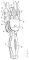
- Fig. 1 The distal shaft end 1 and the traction means guided by the shaft 2 are shown in the form of tension wires 3 - 8, which are guided through the shaft 2 to the proximal end and fastened there by levers, rollers or the like for the purpose of applying tensile forces ,
- the puller wires 3 and 4 serve to pivot the instrument head 9 relative to the distal shaft end 1 about a pivot axis 10.
- the puller wires 5 and 6 serve to pivot the in Fig. 1 shown upper jaw part 11 of a Pliers mouth, whose in Fig. 1 lower jaw part 12 is controllable by the puller wires 7 and 8 in its pivoting movement.
- the jaw parts 11 and 12 are pivotable about a common axis 13, which is arranged with respect to the instrument longitudinal axis 14 at a distance and rotated by 90 ° to the pivot axis 10.
- the instrument head 9 has an intermediate piece 15, which is constructed of a circular in the outer contour of base 16 and from the distally two 180 ° relative to the longitudinal axis 14 staggered legs 17 and 18 extend, between which the jaws 11 and 12 pivotally mounted are, as well as proximally two diametrically arranged and relative to the axis 14 by 180 ° to each other staggered legs 19 and 20 which are relative to the axis 14 offset by 90 ° to the legs 17 and 18 are arranged. Both the legs 17 and 18 and the legs 19 and 20 are arranged near the outer periphery of the base body 16 and continue the circular cross-section of the shaft shape of the shaft 2 to the outside in these areas.
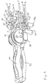
- the legs 19 and 20 are rotatably connected to a shaft 21 which is rotatably mounted in recesses of legs, which are provided at the distal end of the shaft 2.
- a cam plate 24 is fixed against rotation, over which the puller wires 3 and 4 extend, which are each fixed laterally in the disc with their ends.
- the shaft 21 carries laterally of the cam 24 still two spacers 25, which are formed integrally with the cam 24 and the shaft 21 in the described embodiment, but also can be rotatably seated on the shaft 21 in the manner of a washer. It is in this context in particular to the representations in the FIGS. 12-14 where this is shown in detail.
- the proximal-facing legs 19 and 20 of the intermediate piece 15 carry in the area between the shaft 21 and the main body 16 still three parallel axes, namely one, offset at a distance and parallel to the shaft 21, short axis 45 and two laterally offset thereto also arranged short Axes 26a and 27a.
- the axes 45, 26a and 27a are arranged parallel to the shaft 21, the central axes 45 are located in the direction of the longitudinal axis 14 of the instrument behind the shaft 21.
- the bores for the short axes 26a and 27a are by dummy pins 26b and 27b to the outside completed.
- holes the short axes 26 a and 27 a and 45 are incorporated in the intermediate piece 15, is based on Fig. 11 indicated by broken lines. In this case, for example, first insert the short axis 26a into the corresponding bore and then close it by the dummy pin 26b, as on the other side, first introduce the short axis 27a and then close it by the dummy pin
- the central axes 45 carry two pulleys 28 and 29, the short axes 26a and 27a each carry a pulley 30 and 31.
- the pulleys 28 - 31 are identical and freely rotatably mounted, they serve to deflect the puller wires 5-8 and act together with another four identical deflection rollers 32 - 35, which are rotatably mounted on the shaft 21 laterally of the spacers 25 in pairs.
- a pair of rollers each consisting of one of the deflection rollers 28 - 31 and a roller 21 arranged on the rollers 32 - 35 is formed for each of the puller wires 5-8.
- Each pair of rollers is arranged so that regardless of the pivotal position of the instrument head 9 to the shaft 2 of the wrap angle of a puller wire to a pair of rollers always constant is, ie, to the extent that reduces the wrap angle of a seated on the shaft 21 pulley 32 - 35, the wrap angle of the associated pulley 28 - 31 increases to a corresponding extent and vice versa.
- This arrangement causes the position of the puller wires 5 - 8 with respect to the pivotal position of the associated jaws 11 and 12 about the axis 13 is independent of the pivotal position of the instrument head 9 about the pivot axis 10.
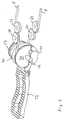
- the forceps jaw parts 11 and 12 are freely movably mounted about the rotation axis 13 and connected to two pull wires 5 and 6 or 7 and 8, wherein a pull wire for pivoting a jaw part in the opening direction and the other pull wire is provided for pivoting the jaw part in the closing direction. Since each jaw part 11 and 12 are each assigned two puller wires 5 and 6 or 7 and 8, the jaw parts 11 and 12 can not only be pivoted towards and away from each other but also together, so that the tool also deviates in a direction deviating from the longitudinal direction 14 Can take direction.
- each jaw part is connected to two cams, namely a large cam 36 arranged close to the longitudinal central axis 14 and a smaller cam disc 37 arranged next to it.
- the large cam 36 has a significantly larger radius than the small cam 37.
- Both cams are designed and arranged so that they are in the in Fig. 1 shown straight position with the forceps jaw closed by a pull wire 5 - 8 are wrapped by more than 90 °. They have an approximately in extension of the forceps jaw extending lateral recess 38 which is channel-like and is provided for receiving the Switzerlandseilendes. Transverse thereto, a bore 39 is provided in which a transverse pin 41 is arranged, in which the Switzerlandseilende is fixed.
- puller wires which move the respective forceps jaw part 11 or 12 towards the other forceps jaw part 12 or 11, ie act on the jaw part in the closing direction, are fixed to the large cam discs 36, which are close to the longitudinal center axis 14 approximately midway between the legs 17 and 18 are arranged.
- the smaller diameter cam plates 37 are connected to the Werdrähten the jaws 11 and 12, which serve to open the forceps jaw.
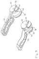
- the jaw members 11 and 12 with the associated cams 36 and 37 are identical in the illustrated embodiment, ie, it can find two identical components use.
- a clearance 40 is formed in the area of the cams between the large cam 36 and the smaller cam 37, which is dimensioned such that upon rotation of the component by 180 ° about the longitudinal axis of the large cam 36 of a jaw member 12 between the two cams 36, 37 of the other jaw part 11 can be incorporated.
- the two large cams 36 are each adjacent to the longitudinal center axis 14 and the smaller cams 37 at a distance next to it.
- the above-described instrument head can be pivoted by applying a tensile force to the pull wires 3 or 4 about the axis 10 in two directions.
- the forceps jaw can be opened by applying tensile forces to the tension wires 5 and 7, this is closed. If tensile forces are simultaneously applied to the tension wires 6 and 7 or 5 and 8, then both jaw parts pivot in the same direction about the axis 13 without changing their angular position relative to one another.
Landscapes
- Health & Medical Sciences (AREA)
- Surgery (AREA)
- Life Sciences & Earth Sciences (AREA)
- Engineering & Computer Science (AREA)
- Medical Informatics (AREA)
- Biomedical Technology (AREA)
- Heart & Thoracic Surgery (AREA)
- Nuclear Medicine, Radiotherapy & Molecular Imaging (AREA)
- Molecular Biology (AREA)
- Animal Behavior & Ethology (AREA)
- General Health & Medical Sciences (AREA)
- Public Health (AREA)
- Veterinary Medicine (AREA)
- Robotics (AREA)
- Ophthalmology & Optometry (AREA)
- Surgical Instruments (AREA)
Claims (12)
- Instrument endoscopique avec une tige (2) et une tête d'instrument (9) disposée à une extrémité de tige (1) distale, laquelle tête comprend un outil avec deux mâchoires (11, 12) aptes à pivoter l'une vers l'autre qui sont conformées pour être commandées à partir de l'extrémité d'instrument proximale à l'aide de moyens de traction (5 - 8) guidés à l'intérieur de la tige (2), au moins une mâchoire (11, 12) comprenant deux disques à came (36, 37) à chacun desquels est attaché un moyen de traction (5 - 8), caractérisé en ce qu'à au moins une mâchoire (11, 12) sont associés deux disques à came (36, 37) de tailles radiales différentes, le disque à came (36) radialement plus grand étant disposé plus proche de l'axe central longitudinal (14) de l'outil que le disque à came (37) radialement plus petit.
- Instrument selon la revendication 1, caractérisé en ce que le disque à came (36) radialement plus grand est associé au moyen de traction (6, 8) pour fermer, et le disque à came (37) radialement plus petit est associé au moyen de traction (5, 7) pour ouvrir la mâchoire (11, 12).
- Instrument selon la revendication 1 ou 2, caractérisé en ce que les disques à came (36, 37) ont de préférence une forme circulaire et sont disposés sur l'axe de pivotement commun (13) des mâchoires (11, 12).
- Instrument selon l'une des revendications précédentes, caractérisé en ce que les moyens de traction (5 - 8) sont attachés chacun aux disques à cames (36, 37) et les enveloppent sur plus que 90°.
- Instrument selon l'une des revendications précédentes, caractérisé en ce qu'une mâchoire (11, 12) est réalisée en une seule pièce avec les deux disques à came correspondantes (36, 37).
- Instrument selon l'une des revendications précédentes, caractérisé en ce que les deux mâchoires (11, 12) sont formées de façon identique.
- Instrument selon l'une des revendications précédentes, caractérisé en ce que les mâchoires (11, 12) sont montées sur une pièce intermédiaire (15) qui fait partie de la tête d'instrument (9) et qui est disposée, de manière pivotante autour d'un axe de pivotement (10), à l'extrémité de tige (1) distale.
- Instrument selon la revendication 7, caractérisé en ce que l'axe de pivotement (10) de la pièce intermédiaire (15) est disposé à distance de, et transversalement par rapport à, l'axe de pivotement (13) des mâchoires (11, 12).
- Instrument selon la revendication 7 ou 8, caractérisé en ce que la pièce intermédiaire (15) comprend un corps de base (16) à partir duquel s'étendent deux branches (17, 18) en direction distale qui reçoivent les mâchoires (11, 12) avec leur axe de pivotement (13), et à partir duquel s'étendent deux branches (19, 20), décalées par rapport à celles-ci de 90° autour de l'axe (14), en direction proximale qui reçoivent l'axe de pivotement (10) de la pièce intermédiaire (15) ainsi que des composants (24, 25) disposés sur celle-ci.
- Instrument selon la revendication 9, caractérisé en ce que les branches (19, 20) orientées en direction proximale sont solidaires en rotation avec un axe (21) sur lequel est disposé, de manière solidaire en rotation, un disque à came (24) sur lequel sont attachés des moyens de traction (3, 4) pour la commande de la position de pivotement de la pièce intermédiaire (15).
- Instrument selon la revendication 10, caractérisé en ce que, entre les branches (19, 20) orientées en direction proximale, est disposée de manière rotative, pour chaque moyen de traction allant vers une mâchoire (11, 12), une paire de rouleaux de renvoi (28 - 35) dont un rouleau de renvoi (32 - 35) respectif est disposé sur l'axe (21) et dont l'autre (28 - 31) est disposé, de manière décalée par rapport à celui-ci, entre l'axe (21) et le corps de base (16).
- Instrument selon la revendication 11, caractérisé en ce que les rouleaux de chaque paire de rouleaux de renvoi (28 - 35) sont disposés l'un par rapport à l'autre de façon que l'angle d'enveloppement du moyen de traction correspondant (5 - 8) autour de la paire de rouleaux de renvoi (28 - 35) est indépendant de la position de pivotement de la pièce intermédiaire (15).
Applications Claiming Priority (2)
| Application Number | Priority Date | Filing Date | Title |
|---|---|---|---|
| DE201210212510 DE102012212510B4 (de) | 2012-07-17 | 2012-07-17 | Endoskopisches Instrument |
| PCT/EP2013/063865 WO2014012780A1 (fr) | 2012-07-17 | 2013-07-01 | Instrument endoscopique |
Publications (2)
| Publication Number | Publication Date |
|---|---|
| EP2874548A1 EP2874548A1 (fr) | 2015-05-27 |
| EP2874548B1 true EP2874548B1 (fr) | 2016-06-01 |
Family
ID=48790373
Family Applications (1)
| Application Number | Title | Priority Date | Filing Date |
|---|---|---|---|
| EP13736817.1A Active EP2874548B1 (fr) | 2012-07-17 | 2013-07-01 | Instrument endoscopique |
Country Status (5)
| Country | Link |
|---|---|
| US (1) | US9615846B2 (fr) |
| EP (1) | EP2874548B1 (fr) |
| CN (1) | CN104470450B (fr) |
| DE (1) | DE102012212510B4 (fr) |
| WO (1) | WO2014012780A1 (fr) |
Cited By (1)
| Publication number | Priority date | Publication date | Assignee | Title |
|---|---|---|---|---|
| CN106826904A (zh) * | 2017-01-23 | 2017-06-13 | 哈尔滨工业大学 | 利用钢丝传动的双输入轴变速比关节 |
Families Citing this family (93)
| Publication number | Priority date | Publication date | Assignee | Title |
|---|---|---|---|---|
| US12290277B2 (en) | 2007-01-02 | 2025-05-06 | Aquabeam, Llc | Tissue resection with pressure sensing |
| US9232959B2 (en) | 2007-01-02 | 2016-01-12 | Aquabeam, Llc | Multi fluid tissue resection methods and devices |
| WO2009111736A1 (fr) | 2008-03-06 | 2009-09-11 | Aquabeam Llc | Ablation des tissus et cautérisation avec de l’énergie optique véhiculée dans un courant de fluide |
| WO2013130895A1 (fr) | 2012-02-29 | 2013-09-06 | Aquabeam, Llc | Résection et traitement de tissu guidés par image automatisée |
| US9339341B2 (en) | 2010-02-08 | 2016-05-17 | Intuitive Surgical Operations, Inc. | Direct pull surgical gripper |
| US12402960B2 (en) | 2010-10-11 | 2025-09-02 | Ecole Polytechnique Federale De Lausanne (Epfl) | Mechanical manipulator for surgical instruments |
| EP2627278B1 (fr) | 2010-10-11 | 2015-03-25 | Ecole Polytechnique Fédérale de Lausanne (EPFL) | Manipulateur mécanique destiné à des instruments chirurgicaux |
| CN103717355B (zh) | 2011-07-27 | 2015-11-25 | 洛桑联邦理工学院 | 用于远程操纵的机械遥控操作装置 |
| US10231867B2 (en) | 2013-01-18 | 2019-03-19 | Auris Health, Inc. | Method, apparatus and system for a water jet |
| WO2014201165A1 (fr) | 2013-06-11 | 2014-12-18 | Auris Surgical Robotics, Inc. | Système pour une chirurgie de cataracte assistée par robot |
| US10426661B2 (en) | 2013-08-13 | 2019-10-01 | Auris Health, Inc. | Method and apparatus for laser assisted cataract surgery |
| JP6554794B2 (ja) * | 2014-01-29 | 2019-08-07 | 住友ベークライト株式会社 | 医療機器 |
| JP6220085B2 (ja) | 2014-02-03 | 2017-10-25 | ディスタルモーション エスエーDistalmotion Sa | 交換可能な遠位装置を備える機械的遠隔操作デバイス |
| US10226305B2 (en) | 2014-02-12 | 2019-03-12 | Covidien Lp | Surgical end effectors and pulley assemblies thereof |
| WO2015122943A1 (fr) * | 2014-02-12 | 2015-08-20 | Covidien Lp | Effecteurs d'extrémité chirurgicaux et ensembles de poulie de ceux-ci |
| WO2015122944A1 (fr) * | 2014-02-12 | 2015-08-20 | Covidien Lp | Effecteurs finaux chirurgicaux et leurs ensembles poulies |
| DE102014205159A1 (de) * | 2014-03-19 | 2015-09-24 | Richard Wolf Gmbh | Robotersystem |
| EP3185808B1 (fr) | 2014-08-27 | 2022-02-23 | DistalMotion SA | Système chirurgical pour techniques de microchirurgie |
| DE102014217796B4 (de) * | 2014-09-05 | 2025-07-17 | Richard Wolf Gmbh | Instrument, insbesondere medizinisch-endoskopisches Instrument oder Technoskop |
| DE102014224268B4 (de) * | 2014-11-27 | 2019-05-16 | Deutsches Zentrum für Luft- und Raumfahrt e.V. | Endoskopisches Instrument sowie Verfahren zum Umgreifen von Strukturen |
| EP4289385A3 (fr) | 2014-12-19 | 2024-03-27 | DistalMotion SA | Instrument chirurgical avec organe terminal effecteur articulé |
| EP3232952B1 (fr) | 2014-12-19 | 2020-02-19 | DistalMotion SA | Instrument chirurgical réutilisable pour interventions non effractives |
| WO2016097873A2 (fr) | 2014-12-19 | 2016-06-23 | Distalmotion Sa | Poignée articulée pour télémanipulateur mécanique |
| US11039820B2 (en) | 2014-12-19 | 2021-06-22 | Distalmotion Sa | Sterile interface for articulated surgical instruments |
| US10864049B2 (en) | 2014-12-19 | 2020-12-15 | Distalmotion Sa | Docking system for mechanical telemanipulator |
| US11344381B2 (en) | 2015-02-17 | 2022-05-31 | Livsmed Inc. | Instrument for surgery |
| KR102153407B1 (ko) | 2015-02-17 | 2020-09-08 | 주식회사 리브스메드 | 수술용 인스트루먼트 |
| US20160287279A1 (en) | 2015-04-01 | 2016-10-06 | Auris Surgical Robotics, Inc. | Microsurgical tool for robotic applications |
| US10568709B2 (en) | 2015-04-09 | 2020-02-25 | Distalmotion Sa | Mechanical teleoperated device for remote manipulation |
| EP3280337B1 (fr) | 2015-04-09 | 2019-11-13 | DistalMotion SA | Instrument manuel articulé |
| US9883858B1 (en) * | 2015-06-15 | 2018-02-06 | Ethicon Endo-Surgery, Llc | Suturing instrument with robotic drive interface |
| EP3340897B1 (fr) | 2015-08-28 | 2024-10-09 | DistalMotion SA | Instrument chirurgical doté d'une force d'actionnement accrue |
| ITUB20154977A1 (it) * | 2015-10-16 | 2017-04-16 | Medical Microinstruments S R L | Strumento medicale e metodo di fabbricazione di detto strumento medicale |
| US10231793B2 (en) | 2015-10-30 | 2019-03-19 | Auris Health, Inc. | Object removal through a percutaneous suction tube |
| US9955986B2 (en) | 2015-10-30 | 2018-05-01 | Auris Surgical Robotics, Inc. | Basket apparatus |
| US9949749B2 (en) | 2015-10-30 | 2018-04-24 | Auris Surgical Robotics, Inc. | Object capture with a basket |
| GB201521812D0 (en) | 2015-12-10 | 2016-01-27 | Cambridge Medical Robotics Ltd | Driving a surgical instrument articulation |
| CN105496512B (zh) * | 2015-12-14 | 2017-12-19 | 李强 | 多指直接控制转腕腹腔镜手术钳 |
| WO2017208320A1 (fr) * | 2016-05-31 | 2017-12-07 | オリンパス株式会社 | Mécanisme de préhension et dispositif de préhension |
| US10869682B2 (en) * | 2016-07-08 | 2020-12-22 | Covidien Lp | Cutting mechanisms for surgical end effector assemblies, instruments, and systems |
| GB2554915B (en) * | 2016-10-14 | 2022-03-02 | Cmr Surgical Ltd | Driving arrangement for articulating a surgical instrument |
| CN106737828B (zh) * | 2017-01-22 | 2019-01-22 | 哈尔滨工业大学 | 用于机器人的钢丝传动变速比转动关节 |
| AU2018244318B2 (en) | 2017-03-28 | 2023-11-16 | Auris Health, Inc. | Shaft actuating handle |
| US10285574B2 (en) | 2017-04-07 | 2019-05-14 | Auris Health, Inc. | Superelastic medical instrument |
| CN110602976B (zh) | 2017-04-07 | 2022-11-15 | 奥瑞斯健康公司 | 患者导引器对准 |
| IT201700041991A1 (it) | 2017-04-14 | 2018-10-14 | Medical Microinstruments Spa | Assieme robotico per microchirurgia |
| US11058503B2 (en) | 2017-05-11 | 2021-07-13 | Distalmotion Sa | Translational instrument interface for surgical robot and surgical robot systems comprising the same |
| GB2563233B (en) * | 2017-06-06 | 2022-09-14 | Cmr Surgical Ltd | Pulley arrangement and pulley guard for articulating a surgical instrument |
| CN111885979A (zh) | 2018-02-07 | 2020-11-03 | 迪斯透莫森公司 | 包括机器人远程操纵器和集成的腹腔镜检查的外科手术机器人系统 |
| US12376927B2 (en) | 2018-02-07 | 2025-08-05 | Distalmotion Sa | Surgical robot systems comprising robotic telemanipulators and integrated laparoscopy |
| EP3761897A4 (fr) | 2018-03-07 | 2021-11-24 | Intuitive Surgical Operations, Inc. | Outils médicaux à faible frottement et à faible encombrement ayant des composants faciles à assembler |
| WO2019173268A1 (fr) | 2018-03-07 | 2019-09-12 | Intuitive Surgical Operations, Inc. | Outils médicaux à faible frottement et à faible profil ayant des composants faciles à assembler |
| US11992286B2 (en) | 2018-03-07 | 2024-05-28 | Intuitive Surgical Operations, Inc. | Low-friction medical tools having roller-assisted tension members |
| WO2019218157A1 (fr) * | 2018-05-15 | 2019-11-21 | 深圳市亚泰光电技术有限公司 | Procédé d'ajustement de direction d'endoscope et endoscope |
| MX2020013241A (es) | 2018-06-07 | 2021-02-22 | Auris Health Inc | Sistemas medicos roboticos con instrumentos de gran fuerza. |
| JP2020002966A (ja) * | 2018-06-26 | 2020-01-09 | 川崎重工業株式会社 | ロータリアクチュエータおよびロボット鉗子 |
| CN112367928A (zh) * | 2018-06-28 | 2021-02-12 | 奥瑞斯健康公司 | 结合滑轮共享的医疗系统 |
| US11259798B2 (en) | 2018-07-16 | 2022-03-01 | Intuitive Surgical Operations, Inc. | Medical devices having tissue grasping surfaces and features for manipulating surgical needles |
| US11612447B2 (en) | 2018-07-19 | 2023-03-28 | Intuitive Surgical Operations, Inc. | Medical devices having three tool members |
| EP3806772A4 (fr) * | 2018-08-15 | 2022-03-30 | Auris Health, Inc. | Instruments médicaux pour cautérisation de tissus |
| WO2020036686A1 (fr) | 2018-08-17 | 2020-02-20 | Auris Health, Inc. | Instrument médical bipolaire |
| WO2020068303A1 (fr) | 2018-09-26 | 2020-04-02 | Auris Health, Inc. | Systèmes et instruments pour aspiration et irrigation |
| US11576738B2 (en) | 2018-10-08 | 2023-02-14 | Auris Health, Inc. | Systems and instruments for tissue sealing |
| US11213287B2 (en) | 2018-11-15 | 2022-01-04 | Intuitive Surgical Operations, Inc. | Support apparatus for a medical retractor device |
| US11291514B2 (en) | 2018-11-15 | 2022-04-05 | Intuitive Surgical Operations, Inc. | Medical devices having multiple blades and methods of use |
| US11950863B2 (en) | 2018-12-20 | 2024-04-09 | Auris Health, Inc | Shielding for wristed instruments |
| CN109730748A (zh) * | 2019-01-14 | 2019-05-10 | 深圳市罗伯医疗科技有限公司 | 提拉操作器械 |
| CN113347938A (zh) | 2019-01-25 | 2021-09-03 | 奥瑞斯健康公司 | 具有加热和冷却能力的血管密封器 |
| CN113613566B (zh) | 2019-03-25 | 2024-10-11 | 奥瑞斯健康公司 | 用于医疗缝合的系统和方法 |
| CN114126529B (zh) * | 2019-06-25 | 2026-03-27 | 奥瑞斯健康公司 | 包括具有混合重定向表面的腕部的医疗器械 |
| WO2020263629A1 (fr) | 2019-06-27 | 2020-12-30 | Auris Health, Inc. | Systèmes et procédés destinés à un applicateur d'agrafes médicales |
| US11109928B2 (en) | 2019-06-28 | 2021-09-07 | Auris Health, Inc. | Medical instruments including wrists with hybrid redirect surfaces |
| US11896330B2 (en) | 2019-08-15 | 2024-02-13 | Auris Health, Inc. | Robotic medical system having multiple medical instruments |
| EP4034349A1 (fr) | 2019-09-26 | 2022-08-03 | Auris Health, Inc. | Systèmes et procédés de détection et d'évitement de collision |
| US12324645B2 (en) | 2019-09-26 | 2025-06-10 | Auris Health, Inc. | Systems and methods for collision avoidance using object models |
| US11737845B2 (en) | 2019-09-30 | 2023-08-29 | Auris Inc. | Medical instrument with a capstan |
| US11737835B2 (en) | 2019-10-29 | 2023-08-29 | Auris Health, Inc. | Braid-reinforced insulation sheath |
| US12357409B2 (en) | 2019-11-21 | 2025-07-15 | Auris Health, Inc. | Systems and methods for draping a surgical system |
| CN111012452A (zh) * | 2019-12-27 | 2020-04-17 | 哈尔滨理工大学 | 一种高自由度的主动柔性针结构 |
| WO2021137104A1 (fr) | 2019-12-31 | 2021-07-08 | Auris Health, Inc. | Système de poulie dynamique |
| KR20220123269A (ko) | 2019-12-31 | 2022-09-06 | 아우리스 헬스, 인코포레이티드 | 고급 바스켓 구동 모드 |
| US12370002B2 (en) | 2020-03-30 | 2025-07-29 | Auris Health, Inc. | Workspace optimization for robotic surgery |
| CN115802975A (zh) | 2020-06-29 | 2023-03-14 | 奥瑞斯健康公司 | 用于检测连杆与外部对象之间的接触的系统和方法 |
| US11357586B2 (en) | 2020-06-30 | 2022-06-14 | Auris Health, Inc. | Systems and methods for saturated robotic movement |
| CN115734765A (zh) | 2020-06-30 | 2023-03-03 | 奥瑞斯健康公司 | 具有碰撞接近度指示器的机器人医疗系统 |
| EP4205687A4 (fr) * | 2020-09-10 | 2024-02-21 | RIVERFIELD Inc. | Dispositif de pince |
| WO2022123658A1 (fr) | 2020-12-08 | 2022-06-16 | リバーフィールド株式会社 | Dispositif de pince et composant de base |
| CN112692862B (zh) * | 2021-03-25 | 2021-10-26 | 成都博恩思医学机器人有限公司 | 一种用于机器人的多自由度器械 |
| EP4401666A1 (fr) | 2021-09-13 | 2024-07-24 | DistalMotion SA | Instruments pour système robotique chirurgical et interfaces pour ceux-ci |
| CN115144281B (zh) * | 2022-09-05 | 2023-03-07 | 之江实验室 | 一种内窥镜蛇骨弯曲疲劳的测试装置及方法 |
| GB2625760B (en) * | 2022-12-22 | 2024-12-25 | Cmr Surgical Ltd | Surgical instrument with interlocking end effector elements |
| US11844585B1 (en) | 2023-02-10 | 2023-12-19 | Distalmotion Sa | Surgical robotics systems and devices having a sterile restart, and methods thereof |
| US20250152263A1 (en) * | 2023-11-09 | 2025-05-15 | Cilag Gmbh International | Pulley supports for end effector wrists |
Family Cites Families (14)
| Publication number | Priority date | Publication date | Assignee | Title |
|---|---|---|---|---|
| US5507773A (en) | 1994-02-18 | 1996-04-16 | Ethicon Endo-Surgery | Cable-actuated jaw assembly for surgical instruments |
| US5792135A (en) * | 1996-05-20 | 1998-08-11 | Intuitive Surgical, Inc. | Articulated surgical instrument for performing minimally invasive surgery with enhanced dexterity and sensitivity |
| US6394998B1 (en) | 1999-01-22 | 2002-05-28 | Intuitive Surgical, Inc. | Surgical tools for use in minimally invasive telesurgical applications |
| US6206903B1 (en) * | 1999-10-08 | 2001-03-27 | Intuitive Surgical, Inc. | Surgical tool with mechanical advantage |
| US6312435B1 (en) | 1999-10-08 | 2001-11-06 | Intuitive Surgical, Inc. | Surgical instrument with extended reach for use in minimally invasive surgery |
| US20030135204A1 (en) * | 2001-02-15 | 2003-07-17 | Endo Via Medical, Inc. | Robotically controlled medical instrument with a flexible section |
| JP4373879B2 (ja) * | 2004-08-26 | 2009-11-25 | 株式会社日立製作所 | 手術器具 |
| US20070208375A1 (en) * | 2006-02-23 | 2007-09-06 | Kouji Nishizawa | Surgical device |
| US8597182B2 (en) * | 2006-04-28 | 2013-12-03 | Intuitive Surgical Operations, Inc. | Robotic endoscopic retractor for use in minimally invasive surgery |
| JP4829005B2 (ja) * | 2006-05-12 | 2011-11-30 | テルモ株式会社 | マニピュレータ |
| US7736254B2 (en) * | 2006-10-12 | 2010-06-15 | Intuitive Surgical Operations, Inc. | Compact cable tension tender device |
| KR101056204B1 (ko) * | 2008-06-27 | 2011-08-11 | 정창욱 | 최소 침습 수술 도구 |
| US8540748B2 (en) * | 2008-07-07 | 2013-09-24 | Intuitive Surgical Operations, Inc. | Surgical instrument wrist |
| US9186219B2 (en) * | 2010-12-17 | 2015-11-17 | Ethicon Endo-Surgery, Inc. | Surgical system and methods for mimicked motion |
-
2012
- 2012-07-17 DE DE201210212510 patent/DE102012212510B4/de not_active Expired - Fee Related
-
2013
- 2013-07-01 CN CN201380038322.9A patent/CN104470450B/zh active Active
- 2013-07-01 US US14/415,277 patent/US9615846B2/en active Active
- 2013-07-01 WO PCT/EP2013/063865 patent/WO2014012780A1/fr not_active Ceased
- 2013-07-01 EP EP13736817.1A patent/EP2874548B1/fr active Active
Cited By (2)
| Publication number | Priority date | Publication date | Assignee | Title |
|---|---|---|---|---|
| CN106826904A (zh) * | 2017-01-23 | 2017-06-13 | 哈尔滨工业大学 | 利用钢丝传动的双输入轴变速比关节 |
| CN106826904B (zh) * | 2017-01-23 | 2019-03-26 | 哈尔滨工业大学 | 利用钢丝传动的双输入轴变速比关节 |
Also Published As
| Publication number | Publication date |
|---|---|
| DE102012212510A1 (de) | 2014-01-23 |
| EP2874548A1 (fr) | 2015-05-27 |
| WO2014012780A1 (fr) | 2014-01-23 |
| DE102012212510B4 (de) | 2014-02-13 |
| CN104470450A (zh) | 2015-03-25 |
| CN104470450B (zh) | 2017-03-01 |
| US9615846B2 (en) | 2017-04-11 |
| US20150127045A1 (en) | 2015-05-07 |
Similar Documents
| Publication | Publication Date | Title |
|---|---|---|
| EP2874548B1 (fr) | Instrument endoscopique | |
| EP1312313B1 (fr) | Forceps chirurgicaux | |
| EP2510887B1 (fr) | Outil pour un instrument de chirurgie micro-invasive | |
| DE102014205159A1 (de) | Robotersystem | |
| DE4104755A1 (de) | Chirurgisches instrument | |
| DE102012219881A1 (de) | Endoskopisches Instrument | |
| DE102008015418A1 (de) | Medizinisches Instrument | |
| DE102011011497A1 (de) | Chirurgisches Instrument | |
| DE10110106A1 (de) | Chirurgische Zange | |
| EP2510889B1 (fr) | Dispositif de manipulation pour un instrument de chirurgie micro-invasive | |
| DE112016001915T5 (de) | Greifmechanismus und Greifvorrichtung | |
| DE10028896B4 (de) | Medizinisches Instrument | |
| DE10327655A1 (de) | Medizinisches Instrument | |
| WO2014124846A1 (fr) | Instrument, en particulier instrument médical d'endoscopie ou technoscope | |
| EP1367948B1 (fr) | Instrument de prehension medical | |
| DE102021119534B4 (de) | Chirurgisches Instrument und Betätigungsvorrichtung dafür | |
| EP4376728B1 (fr) | Instrument chirurgical et dispositif de direction associé | |
| DE102011088003A1 (de) | Medizinisches Instrument | |
| WO2011079897A1 (fr) | Commande d'une tige tubulaire d'un instrument chirurgical | |
| EP1721577B1 (fr) | Instrument endoscopique | |
| DE102014219195A1 (de) | Instrument, insbesondere medizinisch-endoskopisches Schaftinstrument | |
| EP3250133B1 (fr) | Instrument d'arbre pour buts chirurgicals | |
| DE3921935A1 (de) | Chirurgisches instrument | |
| DE102022132686A1 (de) | Medizinisches Instrument zur Fernmanipulation und System für die robotische Chirurgie | |
| DE102021126895A1 (de) | Medizinisches instrument |
Legal Events
| Date | Code | Title | Description |
|---|---|---|---|
| PUAI | Public reference made under article 153(3) epc to a published international application that has entered the european phase |
Free format text: ORIGINAL CODE: 0009012 |
|
| 17P | Request for examination filed |
Effective date: 20150107 |
|
| AK | Designated contracting states |
Kind code of ref document: A1 Designated state(s): AL AT BE BG CH CY CZ DE DK EE ES FI FR GB GR HR HU IE IS IT LI LT LU LV MC MK MT NL NO PL PT RO RS SE SI SK SM TR |
|
| AX | Request for extension of the european patent |
Extension state: BA ME |
|
| DAX | Request for extension of the european patent (deleted) | ||
| GRAP | Despatch of communication of intention to grant a patent |
Free format text: ORIGINAL CODE: EPIDOSNIGR1 |
|
| INTG | Intention to grant announced |
Effective date: 20151217 |
|
| GRAS | Grant fee paid |
Free format text: ORIGINAL CODE: EPIDOSNIGR3 |
|
| GRAA | (expected) grant |
Free format text: ORIGINAL CODE: 0009210 |
|
| AK | Designated contracting states |
Kind code of ref document: B1 Designated state(s): AL AT BE BG CH CY CZ DE DK EE ES FI FR GB GR HR HU IE IS IT LI LT LU LV MC MK MT NL NO PL PT RO RS SE SI SK SM TR |
|
| REG | Reference to a national code |
Ref country code: GB Ref legal event code: FG4D Free format text: NOT ENGLISH |
|
| RIC1 | Information provided on ipc code assigned before grant |
Ipc: A61B 90/00 20160101ALI20160425BHEP Ipc: A61B 17/29 20060101AFI20160425BHEP |
|
| REG | Reference to a national code |
Ref country code: FR Ref legal event code: PLFP Year of fee payment: 4 |
|
| REG | Reference to a national code |
Ref country code: CH Ref legal event code: EP Ref country code: AT Ref legal event code: REF Ref document number: 803362 Country of ref document: AT Kind code of ref document: T Effective date: 20160615 |
|
| REG | Reference to a national code |
Ref country code: IE Ref legal event code: FG4D Free format text: LANGUAGE OF EP DOCUMENT: GERMAN |
|
| REG | Reference to a national code |
Ref country code: DE Ref legal event code: R096 Ref document number: 502013003282 Country of ref document: DE |
|
| REG | Reference to a national code |
Ref country code: LT Ref legal event code: MG4D |
|
| REG | Reference to a national code |
Ref country code: NL Ref legal event code: MP Effective date: 20160601 |
|
| PG25 | Lapsed in a contracting state [announced via postgrant information from national office to epo] |
Ref country code: NO Free format text: LAPSE BECAUSE OF FAILURE TO SUBMIT A TRANSLATION OF THE DESCRIPTION OR TO PAY THE FEE WITHIN THE PRESCRIBED TIME-LIMIT Effective date: 20160901 Ref country code: LT Free format text: LAPSE BECAUSE OF FAILURE TO SUBMIT A TRANSLATION OF THE DESCRIPTION OR TO PAY THE FEE WITHIN THE PRESCRIBED TIME-LIMIT Effective date: 20160601 Ref country code: FI Free format text: LAPSE BECAUSE OF FAILURE TO SUBMIT A TRANSLATION OF THE DESCRIPTION OR TO PAY THE FEE WITHIN THE PRESCRIBED TIME-LIMIT Effective date: 20160601 |
|
| PG25 | Lapsed in a contracting state [announced via postgrant information from national office to epo] |
Ref country code: NL Free format text: LAPSE BECAUSE OF FAILURE TO SUBMIT A TRANSLATION OF THE DESCRIPTION OR TO PAY THE FEE WITHIN THE PRESCRIBED TIME-LIMIT Effective date: 20160601 Ref country code: RS Free format text: LAPSE BECAUSE OF FAILURE TO SUBMIT A TRANSLATION OF THE DESCRIPTION OR TO PAY THE FEE WITHIN THE PRESCRIBED TIME-LIMIT Effective date: 20160601 Ref country code: ES Free format text: LAPSE BECAUSE OF FAILURE TO SUBMIT A TRANSLATION OF THE DESCRIPTION OR TO PAY THE FEE WITHIN THE PRESCRIBED TIME-LIMIT Effective date: 20160601 Ref country code: LV Free format text: LAPSE BECAUSE OF FAILURE TO SUBMIT A TRANSLATION OF THE DESCRIPTION OR TO PAY THE FEE WITHIN THE PRESCRIBED TIME-LIMIT Effective date: 20160601 Ref country code: GR Free format text: LAPSE BECAUSE OF FAILURE TO SUBMIT A TRANSLATION OF THE DESCRIPTION OR TO PAY THE FEE WITHIN THE PRESCRIBED TIME-LIMIT Effective date: 20160902 Ref country code: HR Free format text: LAPSE BECAUSE OF FAILURE TO SUBMIT A TRANSLATION OF THE DESCRIPTION OR TO PAY THE FEE WITHIN THE PRESCRIBED TIME-LIMIT Effective date: 20160601 Ref country code: SE Free format text: LAPSE BECAUSE OF FAILURE TO SUBMIT A TRANSLATION OF THE DESCRIPTION OR TO PAY THE FEE WITHIN THE PRESCRIBED TIME-LIMIT Effective date: 20160601 |
|
| PG25 | Lapsed in a contracting state [announced via postgrant information from national office to epo] |
Ref country code: BE Free format text: LAPSE BECAUSE OF NON-PAYMENT OF DUE FEES Effective date: 20160731 |
|
| PG25 | Lapsed in a contracting state [announced via postgrant information from national office to epo] |
Ref country code: IS Free format text: LAPSE BECAUSE OF FAILURE TO SUBMIT A TRANSLATION OF THE DESCRIPTION OR TO PAY THE FEE WITHIN THE PRESCRIBED TIME-LIMIT Effective date: 20161001 Ref country code: SK Free format text: LAPSE BECAUSE OF FAILURE TO SUBMIT A TRANSLATION OF THE DESCRIPTION OR TO PAY THE FEE WITHIN THE PRESCRIBED TIME-LIMIT Effective date: 20160601 Ref country code: CZ Free format text: LAPSE BECAUSE OF FAILURE TO SUBMIT A TRANSLATION OF THE DESCRIPTION OR TO PAY THE FEE WITHIN THE PRESCRIBED TIME-LIMIT Effective date: 20160601 Ref country code: RO Free format text: LAPSE BECAUSE OF FAILURE TO SUBMIT A TRANSLATION OF THE DESCRIPTION OR TO PAY THE FEE WITHIN THE PRESCRIBED TIME-LIMIT Effective date: 20160601 Ref country code: EE Free format text: LAPSE BECAUSE OF FAILURE TO SUBMIT A TRANSLATION OF THE DESCRIPTION OR TO PAY THE FEE WITHIN THE PRESCRIBED TIME-LIMIT Effective date: 20160601 Ref country code: IT Free format text: LAPSE BECAUSE OF FAILURE TO SUBMIT A TRANSLATION OF THE DESCRIPTION OR TO PAY THE FEE WITHIN THE PRESCRIBED TIME-LIMIT Effective date: 20160601 |
|
| PG25 | Lapsed in a contracting state [announced via postgrant information from national office to epo] |
Ref country code: PT Free format text: LAPSE BECAUSE OF FAILURE TO SUBMIT A TRANSLATION OF THE DESCRIPTION OR TO PAY THE FEE WITHIN THE PRESCRIBED TIME-LIMIT Effective date: 20161003 Ref country code: PL Free format text: LAPSE BECAUSE OF FAILURE TO SUBMIT A TRANSLATION OF THE DESCRIPTION OR TO PAY THE FEE WITHIN THE PRESCRIBED TIME-LIMIT Effective date: 20160601 Ref country code: SM Free format text: LAPSE BECAUSE OF FAILURE TO SUBMIT A TRANSLATION OF THE DESCRIPTION OR TO PAY THE FEE WITHIN THE PRESCRIBED TIME-LIMIT Effective date: 20160601 |
|
| REG | Reference to a national code |
Ref country code: CH Ref legal event code: PL |
|
| REG | Reference to a national code |
Ref country code: DE Ref legal event code: R097 Ref document number: 502013003282 Country of ref document: DE |
|
| PG25 | Lapsed in a contracting state [announced via postgrant information from national office to epo] |
Ref country code: MC Free format text: LAPSE BECAUSE OF FAILURE TO SUBMIT A TRANSLATION OF THE DESCRIPTION OR TO PAY THE FEE WITHIN THE PRESCRIBED TIME-LIMIT Effective date: 20160601 |
|
| PLBE | No opposition filed within time limit |
Free format text: ORIGINAL CODE: 0009261 |
|
| STAA | Information on the status of an ep patent application or granted ep patent |
Free format text: STATUS: NO OPPOSITION FILED WITHIN TIME LIMIT |
|
| PG25 | Lapsed in a contracting state [announced via postgrant information from national office to epo] |
Ref country code: LI Free format text: LAPSE BECAUSE OF NON-PAYMENT OF DUE FEES Effective date: 20160731 Ref country code: CH Free format text: LAPSE BECAUSE OF NON-PAYMENT OF DUE FEES Effective date: 20160731 |
|
| REG | Reference to a national code |
Ref country code: IE Ref legal event code: MM4A |
|
| 26N | No opposition filed |
Effective date: 20170302 |
|
| PG25 | Lapsed in a contracting state [announced via postgrant information from national office to epo] |
Ref country code: SI Free format text: LAPSE BECAUSE OF FAILURE TO SUBMIT A TRANSLATION OF THE DESCRIPTION OR TO PAY THE FEE WITHIN THE PRESCRIBED TIME-LIMIT Effective date: 20160601 Ref country code: DK Free format text: LAPSE BECAUSE OF FAILURE TO SUBMIT A TRANSLATION OF THE DESCRIPTION OR TO PAY THE FEE WITHIN THE PRESCRIBED TIME-LIMIT Effective date: 20160601 |
|
| REG | Reference to a national code |
Ref country code: FR Ref legal event code: PLFP Year of fee payment: 5 |
|
| PG25 | Lapsed in a contracting state [announced via postgrant information from national office to epo] |
Ref country code: IE Free format text: LAPSE BECAUSE OF NON-PAYMENT OF DUE FEES Effective date: 20160701 |
|
| PG25 | Lapsed in a contracting state [announced via postgrant information from national office to epo] |
Ref country code: LU Free format text: LAPSE BECAUSE OF NON-PAYMENT OF DUE FEES Effective date: 20160701 |
|
| PG25 | Lapsed in a contracting state [announced via postgrant information from national office to epo] |
Ref country code: HU Free format text: LAPSE BECAUSE OF FAILURE TO SUBMIT A TRANSLATION OF THE DESCRIPTION OR TO PAY THE FEE WITHIN THE PRESCRIBED TIME-LIMIT; INVALID AB INITIO Effective date: 20130701 |
|
| PG25 | Lapsed in a contracting state [announced via postgrant information from national office to epo] |
Ref country code: MT Free format text: LAPSE BECAUSE OF FAILURE TO SUBMIT A TRANSLATION OF THE DESCRIPTION OR TO PAY THE FEE WITHIN THE PRESCRIBED TIME-LIMIT Effective date: 20160601 Ref country code: MK Free format text: LAPSE BECAUSE OF FAILURE TO SUBMIT A TRANSLATION OF THE DESCRIPTION OR TO PAY THE FEE WITHIN THE PRESCRIBED TIME-LIMIT Effective date: 20160601 Ref country code: CY Free format text: LAPSE BECAUSE OF FAILURE TO SUBMIT A TRANSLATION OF THE DESCRIPTION OR TO PAY THE FEE WITHIN THE PRESCRIBED TIME-LIMIT Effective date: 20160601 |
|
| REG | Reference to a national code |
Ref country code: FR Ref legal event code: PLFP Year of fee payment: 6 |
|
| PG25 | Lapsed in a contracting state [announced via postgrant information from national office to epo] |
Ref country code: BG Free format text: LAPSE BECAUSE OF FAILURE TO SUBMIT A TRANSLATION OF THE DESCRIPTION OR TO PAY THE FEE WITHIN THE PRESCRIBED TIME-LIMIT Effective date: 20160601 |
|
| PG25 | Lapsed in a contracting state [announced via postgrant information from national office to epo] |
Ref country code: TR Free format text: LAPSE BECAUSE OF FAILURE TO SUBMIT A TRANSLATION OF THE DESCRIPTION OR TO PAY THE FEE WITHIN THE PRESCRIBED TIME-LIMIT Effective date: 20160601 Ref country code: AL Free format text: LAPSE BECAUSE OF FAILURE TO SUBMIT A TRANSLATION OF THE DESCRIPTION OR TO PAY THE FEE WITHIN THE PRESCRIBED TIME-LIMIT Effective date: 20160601 |
|
| REG | Reference to a national code |
Ref country code: AT Ref legal event code: MM01 Ref document number: 803362 Country of ref document: AT Kind code of ref document: T Effective date: 20180701 |
|
| PG25 | Lapsed in a contracting state [announced via postgrant information from national office to epo] |
Ref country code: AT Free format text: LAPSE BECAUSE OF NON-PAYMENT OF DUE FEES Effective date: 20180701 |
|
| PGFP | Annual fee paid to national office [announced via postgrant information from national office to epo] |
Ref country code: DE Payment date: 20250728 Year of fee payment: 13 |
|
| PGFP | Annual fee paid to national office [announced via postgrant information from national office to epo] |
Ref country code: GB Payment date: 20250724 Year of fee payment: 13 |
|
| PGFP | Annual fee paid to national office [announced via postgrant information from national office to epo] |
Ref country code: FR Payment date: 20250723 Year of fee payment: 13 |