EP2874591B1 - Sensorized postural couch for physical therapy - Google Patents
Sensorized postural couch for physical therapy Download PDFInfo
- Publication number
- EP2874591B1 EP2874591B1 EP13739776.6A EP13739776A EP2874591B1 EP 2874591 B1 EP2874591 B1 EP 2874591B1 EP 13739776 A EP13739776 A EP 13739776A EP 2874591 B1 EP2874591 B1 EP 2874591B1
- Authority
- EP
- European Patent Office
- Prior art keywords
- couch
- panels
- panel
- pivoted
- patient
- Prior art date
- Legal status (The legal status is an assumption and is not a legal conclusion. Google has not performed a legal analysis and makes no representation as to the accuracy of the status listed.)
- Active
Links
Images
Classifications
-
- A—HUMAN NECESSITIES
- A61—MEDICAL OR VETERINARY SCIENCE; HYGIENE
- A61B—DIAGNOSIS; SURGERY; IDENTIFICATION
- A61B5/00—Measuring for diagnostic purposes; Identification of persons
- A61B5/45—For evaluating or diagnosing the musculoskeletal system or teeth
- A61B5/4519—Muscles
-
- A—HUMAN NECESSITIES
- A61—MEDICAL OR VETERINARY SCIENCE; HYGIENE
- A61G—TRANSPORT, PERSONAL CONVEYANCES, OR ACCOMMODATION SPECIALLY ADAPTED FOR PATIENTS OR DISABLED PERSONS; OPERATING TABLES OR CHAIRS; CHAIRS FOR DENTISTRY; FUNERAL DEVICES
- A61G13/00—Operating tables; Auxiliary appliances therefor
- A61G13/009—Physiotherapeutic tables, beds or platforms; Chiropractic or osteopathic tables
-
- A—HUMAN NECESSITIES
- A61—MEDICAL OR VETERINARY SCIENCE; HYGIENE
- A61B—DIAGNOSIS; SURGERY; IDENTIFICATION
- A61B5/00—Measuring for diagnostic purposes; Identification of persons
- A61B5/103—Measuring devices for testing the shape, pattern, colour, size or movement of the body or parts thereof, for diagnostic purposes
- A61B5/1036—Measuring load distribution, e.g. podologic studies
-
- A—HUMAN NECESSITIES
- A61—MEDICAL OR VETERINARY SCIENCE; HYGIENE
- A61B—DIAGNOSIS; SURGERY; IDENTIFICATION
- A61B5/00—Measuring for diagnostic purposes; Identification of persons
- A61B5/103—Measuring devices for testing the shape, pattern, colour, size or movement of the body or parts thereof, for diagnostic purposes
- A61B5/11—Measuring movement of the entire body or parts thereof, e.g. head or hand tremor or mobility of a limb
- A61B5/1121—Determining geometric values, e.g. centre of rotation or angular range of movement
-
- A—HUMAN NECESSITIES
- A61—MEDICAL OR VETERINARY SCIENCE; HYGIENE
- A61B—DIAGNOSIS; SURGERY; IDENTIFICATION
- A61B5/00—Measuring for diagnostic purposes; Identification of persons
- A61B5/74—Details of notification to user or communication with user or patient; User input means
- A61B5/742—Details of notification to user or communication with user or patient; User input means using visual displays
-
- A—HUMAN NECESSITIES
- A61—MEDICAL OR VETERINARY SCIENCE; HYGIENE
- A61G—TRANSPORT, PERSONAL CONVEYANCES, OR ACCOMMODATION SPECIALLY ADAPTED FOR PATIENTS OR DISABLED PERSONS; OPERATING TABLES OR CHAIRS; CHAIRS FOR DENTISTRY; FUNERAL DEVICES
- A61G13/00—Operating tables; Auxiliary appliances therefor
- A61G13/02—Adjustable operating tables; Controls therefor
- A61G13/08—Adjustable operating tables; Controls therefor the table being divided into different adjustable sections
-
- A—HUMAN NECESSITIES
- A61—MEDICAL OR VETERINARY SCIENCE; HYGIENE
- A61G—TRANSPORT, PERSONAL CONVEYANCES, OR ACCOMMODATION SPECIALLY ADAPTED FOR PATIENTS OR DISABLED PERSONS; OPERATING TABLES OR CHAIRS; CHAIRS FOR DENTISTRY; FUNERAL DEVICES
- A61G2203/00—General characteristics of devices
- A61G2203/30—General characteristics of devices characterised by sensor means
- A61G2203/32—General characteristics of devices characterised by sensor means for force
-
- A—HUMAN NECESSITIES
- A61—MEDICAL OR VETERINARY SCIENCE; HYGIENE
- A61G—TRANSPORT, PERSONAL CONVEYANCES, OR ACCOMMODATION SPECIALLY ADAPTED FOR PATIENTS OR DISABLED PERSONS; OPERATING TABLES OR CHAIRS; CHAIRS FOR DENTISTRY; FUNERAL DEVICES
- A61G2203/00—General characteristics of devices
- A61G2203/30—General characteristics of devices characterised by sensor means
- A61G2203/36—General characteristics of devices characterised by sensor means for motion
-
- A—HUMAN NECESSITIES
- A61—MEDICAL OR VETERINARY SCIENCE; HYGIENE
- A61G—TRANSPORT, PERSONAL CONVEYANCES, OR ACCOMMODATION SPECIALLY ADAPTED FOR PATIENTS OR DISABLED PERSONS; OPERATING TABLES OR CHAIRS; CHAIRS FOR DENTISTRY; FUNERAL DEVICES
- A61G2203/00—General characteristics of devices
- A61G2203/30—General characteristics of devices characterised by sensor means
- A61G2203/42—General characteristics of devices characterised by sensor means for inclination
Definitions
- the present Invention relates to a sensorized postural couch of variable geometry for physical therapy, and a method for verifying the muscular tension of a patient before and after patient treatment.
- Articulated couches are also known, provided with means for manually or electrically moving one or more of their parts. Examples of couches can be found in US2006/123546 , WO2005/034827 , US6971997 and US5774915 .
- An object of the present invention is to provide a sensorized couch of variable geometry for physical therapy which enables the operator to comprehend the structure and posture of the patient.
- Another object is to provide a couch which can give an evaluation of the anatomical-functional tensions and/or rotations in the three main planes of the articular body movement (sagittal, transverse and frontal).
- a further object is to measure the tensions of all anatomical districts to obtain a single indicator able to give the exact tension exerted on all rear chains (muscular, myofascial).
- Another object is to have a system able not only to make postural measurements, but also to display post-evaluation physiotherapeutic treatment.
- a sensorized couch of variable geometry for physical therapy comprising: a base; a patient support comprising at least two panels; each panel of said at least two panels being pivoted to each panel adjacent to it; characterised in that each panel of said at least two panels comprises at least three load sensors and an accelerometer.
- a method for evaluating the muscular tension of a patient comprising the steps of measuring first loads applied by the patient's body when in the extended supine position on a couch in its flat position, by sensors applied to said couch; measuring second loads applied by the patient's body when in the extended position on said couch in its position inclined by a predetermined angle, by sensors applied to said couch; calculating a first index of muscular tension of the patient's body as the difference between said first and second loads.
- the physical therapy couch for manual treatment and postural evaluation, has a variable geometry and is provided with a network of electronic sensors controlled by a computer.
- variable geometry together with the load and inclination measuring devices enable acquisition of the forces applied passively by the patient's body and the pressures exerted actively by the therapist during treatment.
- the postural couch is composed of four independent sections which determine the load exerted by the body in the specific body districts, namely: lower limbs, pelvis, lumbar trunk, scapular trunk, and head.
- Each individual section is able to determine the load exerted and its position on the panel, similarly to the Centre of Pressure (CoP) of stabilometric systems.
- CoP Centre of Pressure
- the angles configurable by the support panels of the postural couch ensure subject positioning under predefined and controlled stretching conditions.
- the new system moreover completely perceives all parts of the supported body. This enables a single indicator to be obtained able to give the exact tension of all the rear chains (muscular and myofascial).
- a sensorized couch 1 of variable geometry for physical therapy comprises a base 10 on which the couch 1 rests.
- the base is a foot-supported tubular structure from which two pairs of vertical bars 11 and 12 rise.
- the pair of bars 11 is positioned at one end of the base 10 and the pair of bars 12 is positioned at about 2/3 from the first pair of bars 11.
- a corner of the base of a triangular structure 13 and 14 is pivoted to each of the vertical bars 11 and 12.
- the bar 15 is fixed, approximately at its centre, to one end of a controlled linear actuator 16.
- the other end of the linear actuator 16 is fixed to one end of the base 10, namely that at which the pair of vertical bars 11 is present, it being fixed below them.
- each of the triangular structures 13 and 14 is pivoted to a support 17 of the couch 1, substantial at its central point.
- the couch 1 is pivoted on the central upper summit of the support 17.
- the triangular structures 13 and 14 are partially concealed within the base 10.
- the support surface 20 for the patient comprises four panels connected together but independent in terms of angularity.
- the panel 21 is that on which the scapular trunk and head rest.
- the panel 22, is that on which the lumbar trunk rests.
- the panel 23 is that on which the pelvis and femoral part of the leg rest.
- the pannel 24 is that on which the lower limbs (tibial part) rest.
- the support surface 20 for the patient can have a smaller number of support panels, for example two in number: one for the upper trunk and one for the lower trunk.
- the support 17 is pivoted to the support surface 20, and in particular is pivoted to the two most inner sides of the panels 22 and 23.
- the width of the panels 21-24 is substantially the same.
- the length of the panels 21-24 varies, depending on the length of the aforedefined human body portions. In particular the panel 24 is the longest, the panel 21 is of length slightly less than the panel 24, and the two panels 22 and 23 are still shorter but of substantially the same length.
- That side of the panel 22 opposite the side pivoted to the support 17 is pivoted to one end of a controlled linear actuator 30, the other end of which is pivoted on a side of the arc (right in the figure) of the support 17.
- the most outer side of the panel 21 is fixed to one end of a manually operated piston 31, the other end of which is pivoted to the outer side of the panel 22.
- That side of the panel 23 opposite the side pivoted to the support 17 is pivoted to one end of a controlled linear actuator 32, the other end of which is pivoted on a side of the arc (left in the figure) of the support 17.
- the most outer side of the panel 24 is fixed to one end of a manually operated piston 33, the other end of which is pivoted to the outer side of the panel 23.
- the controlled linear actuators 16 and 30 used in the present invention are preferably electrical, and when commanded drive forwards and rearwards a rod which emerges from the motor itself.
- linear actuators such as mechanical, hydraulic, pneumatic.
- the linear actuator 16 and the dimensions of the structure formed by the elements 13, 14, 15 and 17 enable the couch to be raised from the floor by an overall distance from 40 cm to 120 cm.
- the inclination of the lumbar support panel 22 (and of the scapular panel 21 connected to it) can be varied by the linear actuator 30 from -10° to +55° about a horizontal axis.
- the inclination of the pelvis support panel 23 (and of the lower limb panel 24 connected to it) can be varied by the linear actuator 32 from -10° to +45° about a horizontal axis
- the inclination of the scapular support panel 21 can be varied by the manually operated piston 31 from -40° to +45° about the panel 22.
- the inclination of the leg/foot support panel 24 can be varied by the manually operated piston 33 from -40° to +45° about the panel 23.
- Each of the panels 21-24 comprises three layers.
- three load sensors 45 and a monoaxial accelerometer 46 are positioned in the layer 41 of each panel 21-24.
- the three load sensors 45 of each panel 21-24 are positioned equidistant at 120° apart, directed along the longitudinal axis with one of their joining axes positioned along the longitudinal axis of the support surface 20.
- the accelerometer 46 is preferably positioned, on each panel, with its axis coaxial with that axis joining two load sensors 45 which is parallel to one side of the panel. It is used principally as an inclinometer for the various panels.
- a further fluctuating inertial sensor 47 is preferably provided freely positionable for angular kinesthetic measurements.
- the individual load sensors 45 have a maximum capacity of 109 kg, a non-linearity of ⁇ 0.04% and a resolution equal to 25 g.
- the accelerometers 46 have a resolution level of 0.2 degrees within a range of +90° to -90°, such as to enable the inclinations of each panel to be measured with sufficient precision.
- the inertial sensor used for angular degree measurements, is a sensor provided with a gyroscope, accelerometer and triaxial magnetometer.
- the main uses of the inertial sensors integrated with the postural couch are basically two in number: kinesiological evaluation pre and post treatment and real time monitoring of the articular district during manipulative treatment (e.g. extremely delicate cervical manipulation). Both the angular evaluations are integrated by the applied load measurements. This signifies that the system determines whether the patient's articulations achieve the same range of motion in specular dx-sx manner, while maintaining the same muscular and myofascial tensions.
- the signals of the load sensors 45, of the accelerometers 46 and of the inertial sensors 47, and the commands of the linear actuators 30 and 32, are connected electrically to a concentrator 50 and then to a computer 51, which comprises a monitor 52 positioned on the base 10 (or in the vicinity thereof).
- All the sensors are connected to the concentrator 50 which comprises a single electric A/D conversion circuit which consolidates the measured data and communicates with the computer 51 in synchronous mode with frequency configurable from 20Hz to 40Hz.
- the computer 51 contains programmes able to obtain the measurements of the various sensors from the concentrator 50, and to calculate the barycentre of the forces of each panel 21-24 by triangulation of the groups of sensors 45.
- the computer 51 enables all the-physical variables in play during evaluation and treatment to be displayed in real time on the monitor 52, as can be seen for example in Figure 5 , which indicates for each panel the loads thereon to the right and left of the linear actuator axis and indicates the position of the barycentre for each panel, where T indicates the lower limb portion, P indicates the pelvis potion, L indicates the lumbar trunk portion, S indicates the scapular and head portion, and Tot indicates the total load, all divided into the right and left part, in percentage and absolute values.
- the patient can also be subjected to postural training sessions with the aid of visual and acoustic feedback.
- the patient is invited by the computer 52 to carry out articular twisting at various levels (scapular, lumbar, pelvis) to attain the proposed targets.
- the subject is placed on the postural couch 1 in a perfectly horizontal supine position (zero position) and while in this position the total weight is measured. Subsequently, the system by changing the configuration puts the subject into a stretching situation by an angle of 120° or 105° or another predetermined angle (evaluation position).
- the load measured by the couch panels is the resultant of the patient's weight plus the tension exerted by the rear chain, from which the overall tension index is derived (by subtracting the weight), the various tensions on the separate anatomical segments (nape, scapular, lumbar, pelvis, legs and feet) then being determined.
- their misalignments i.e. the positioning of the tension of all muscular chains
- the values and misalignments are displayed on the monitor 52 by suitable graphs.
- the couch 1, used to evaluate the tension indexes, is the same as used in the physiotherapeutic treatment.
- the function of evaluating the muscular tensions and hence of postural evaluation can be carried out simultaneously and on the same system as the treatment function, hence enabling the operator to close the rehabilitative process loop without moving the patient.
- the system inter alia enables the physiotherapeutic work carried out by the operator on the subject to be monitored, hence quantifying and memorizing the intensity of its action and the articular levels applied to the treated anatomical parts by means of integrated sensors.
- the therapist is able to note the intensity of a given manoeuvre in terms of pressure exerted, consequent muscular tension and articular levels applied. In this manner the operator can model his/her intervention by controlled and precise clinical movements.
- the entire working session can be filed digitally on the computer 51 for possible future technical re-evaluations and comparison, and to document the entire treatment.
- Positioning is then repeated as in the first step (evaluation position) and the current tension exerted by the patient is monitored, hence enabling the operator and patient to evaluate the results obtained by the therapy, by comparing the two measurements.
- the method comprises the following steps:
- the muscular tension index can be evaluated as aforedescribed and then memorized.
- a sensorized couch of variable geometry for physical therapy is hence made available by which the tension of the patient's rear chain can be verified, with the operator operating on one and the same couch and observing in real time the forces applied, after which the patient's muscular tension can again be verified in order to observe the improvements achieved by the therapy.
- All the acquired data can be memorized for subsequent comparison and to maintain the patient's history.
- the materials used for the couch and its dimensions can be chosen at will depending on requirements and on the state of the art.
Landscapes
- Health & Medical Sciences (AREA)
- Life Sciences & Earth Sciences (AREA)
- General Health & Medical Sciences (AREA)
- Veterinary Medicine (AREA)
- Public Health (AREA)
- Engineering & Computer Science (AREA)
- Biomedical Technology (AREA)
- Animal Behavior & Ethology (AREA)
- Biophysics (AREA)
- Physics & Mathematics (AREA)
- Medical Informatics (AREA)
- Surgery (AREA)
- Molecular Biology (AREA)
- Pathology (AREA)
- Heart & Thoracic Surgery (AREA)
- Dentistry (AREA)
- Oral & Maxillofacial Surgery (AREA)
- Orthopedic Medicine & Surgery (AREA)
- Physical Education & Sports Medicine (AREA)
- Rehabilitation Therapy (AREA)
- Geometry (AREA)
- Physiology (AREA)
- Rheumatology (AREA)
- Measurement Of The Respiration, Hearing Ability, Form, And Blood Characteristics Of Living Organisms (AREA)
- Footwear And Its Accessory, Manufacturing Method And Apparatuses (AREA)
- Transplanting Machines (AREA)
Description
- The present Invention relates to a sensorized postural couch of variable geometry for physical therapy, and a method for verifying the muscular tension of a patient before and after patient treatment.
- Couches or benches for physical therapy are known, often modular and positionable to enable the therapist to correctly position the patient and facilitate therapeutic operations thereon.
- Articulated couches are also known, provided with means for manually or electrically moving one or more of their parts. Examples of couches can be found in
US2006/123546 ,WO2005/034827 ,US6971997 andUS5774915 . - An object of the present invention is to provide a sensorized couch of variable geometry for physical therapy which enables the operator to comprehend the structure and posture of the patient.
- Another object is to provide a couch which can give an evaluation of the anatomical-functional tensions and/or rotations in the three main planes of the articular body movement (sagittal, transverse and frontal).
- A further object is to measure the tensions of all anatomical districts to obtain a single indicator able to give the exact tension exerted on all rear chains (muscular, myofascial).
- Another object is to have a system able not only to make postural measurements, but also to display post-evaluation physiotherapeutic treatment.
- These and further objects are attained according to the present invention by a sensorized couch of variable geometry for physical therapy comprising: a base; a patient support comprising at least two panels; each panel of said at least two panels being pivoted to each panel adjacent to it; characterised in that each panel of said at least two panels comprises at least three load sensors and an accelerometer.
- These objects are also attained by a method for evaluating the muscular tension of a patient, comprising the steps of measuring first loads applied by the patient's body when in the extended supine position on a couch in its flat position, by sensors applied to said couch; measuring second loads applied by the patient's body when in the extended position on said couch in its position inclined by a predetermined angle, by sensors applied to said couch; calculating a first index of muscular tension of the patient's body as the difference between said first and second loads.
- Further characteristics of the invention are described in the independent claims.
- This solution has various advantages compared with the solutions of the known art.
- The physical therapy couch, according to the present invention, for manual treatment and postural evaluation, has a variable geometry and is provided with a network of electronic sensors controlled by a computer.
- The particular variable geometry together with the load and inclination measuring devices enable acquisition of the forces applied passively by the patient's body and the pressures exerted actively by the therapist during treatment.
- The postural couch is composed of four independent sections which determine the load exerted by the body in the specific body districts, namely: lower limbs, pelvis, lumbar trunk, scapular trunk, and head.
- Each individual section is able to determine the load exerted and its position on the panel, similarly to the Centre of Pressure (CoP) of stabilometric systems.
- The angles configurable by the support panels of the postural couch ensure subject positioning under predefined and controlled stretching conditions.
- This technological solution fully satisfies the requirement of monitoring the tensions and the rotations of the rear chain in the three main planes of the articulated body movement (sagittal, transverse and frontal), hence determining the load variation of the tensions on the entire support surface.
- The new system moreover completely perceives all parts of the supported body. This enables a single indicator to be obtained able to give the exact tension of all the rear chains (muscular and myofascial).
- The characteristics and advantages of the present invention will be apparent from the ensuing detailed description of a preferred embodiment thereof, illustrated by way of non-limiting example in the accompanying drawings, in which:
-
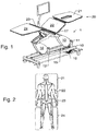
Figure 1 shows a perspective view of a couch of variable geometry for physical therapy, in accordance with the present invention; -
Figure 2 shows a design of a human figure with reference to the support surfaces of the sensorized couch of variable geometry for physical therapy, in accordance with the present invention; -
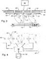
Figure 3 shows a front view of a sensorized couch of variable geometry for physical therapy, partly broken down into its elements, in accordance with the present invention; -
Figure 4 shows a block scheme of the sensors positioned on the couch of variable geometry for physical therapy, and on the control means associated therewith, in accordance with the present invention; -
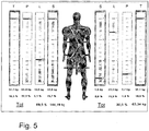
Figure 5 shows an example of image representation of a computer connected to a couch of variable geometry for physical therapy, in accordance with the present invention. - With reference to the accompanying figures, a
sensorized couch 1 of variable geometry for physical therapy according to the present invention comprises abase 10 on which thecouch 1 rests. - The base is a foot-supported tubular structure from which two pairs of
vertical bars bars 11 is positioned at one end of thebase 10 and the pair ofbars 12 is positioned at about 2/3 from the first pair ofbars 11. - A corner of the base of a
triangular structure vertical bars - The other corner of the base of each of the
triangular structures horizontal bar 15. - The
bar 15 is fixed, approximately at its centre, to one end of a controlledlinear actuator 16. The other end of thelinear actuator 16 is fixed to one end of thebase 10, namely that at which the pair ofvertical bars 11 is present, it being fixed below them. - The vertex of each of the
triangular structures support 17 of thecouch 1, substantial at its central point. Thecouch 1 is pivoted on the central upper summit of thesupport 17. - To raise the
couch 1 thelinear actuator 16 is operated, which by thrusting thebar 15 raises thetriangular structures support 17 upwards raises thecouch 1. By operating thelinear actuator 16 in the reverse direction the couch descends. - If the couch is totally lowered, the
triangular structures base 10. - In the embodiment shown in the figures, the
support surface 20 for the patient comprises four panels connected together but independent in terms of angularity. Thepanel 21 is that on which the scapular trunk and head rest. Thepanel 22, is that on which the lumbar trunk rests. Thepanel 23 is that on which the pelvis and femoral part of the leg rest. Thepannel 24 is that on which the lower limbs (tibial part) rest. - In a more simplified embodiment, the
support surface 20 for the patient can have a smaller number of support panels, for example two in number: one for the upper trunk and one for the lower trunk. - The
support 17 is pivoted to thesupport surface 20, and in particular is pivoted to the two most inner sides of thepanels - The width of the panels 21-24 is substantially the same. The length of the panels 21-24 varies, depending on the length of the aforedefined human body portions. In particular the
panel 24 is the longest, thepanel 21 is of length slightly less than thepanel 24, and the twopanels - That side of the
panel 22 opposite the side pivoted to thesupport 17 is pivoted to one end of a controlledlinear actuator 30, the other end of which is pivoted on a side of the arc (right in the figure) of thesupport 17. - The most outer side of the
panel 21 is fixed to one end of a manually operatedpiston 31, the other end of which is pivoted to the outer side of thepanel 22. - That side of the
panel 23 opposite the side pivoted to thesupport 17 is pivoted to one end of a controlledlinear actuator 32, the other end of which is pivoted on a side of the arc (left in the figure) of thesupport 17. - The most outer side of the
panel 24 is fixed to one end of a manually operatedpiston 33, the other end of which is pivoted to the outer side of thepanel 23. - The controlled
linear actuators - Alternatively other types of linear actuators can be used such as mechanical, hydraulic, pneumatic.
- The
linear actuator 16 and the dimensions of the structure formed by theelements - The inclination of the lumbar support panel 22 (and of the
scapular panel 21 connected to it) can be varied by thelinear actuator 30 from -10° to +55° about a horizontal axis. - The inclination of the pelvis support panel 23 (and of the
lower limb panel 24 connected to it) can be varied by thelinear actuator 32 from -10° to +45° about a horizontal axis - The inclination of the
scapular support panel 21 can be varied by the manually operatedpiston 31 from -40° to +45° about thepanel 22. - The inclination of the leg/
foot support panel 24 can be varied by the manually operatedpiston 33 from -40° to +45° about thepanel 23. - Each of the panels 21-24 comprises three layers.
- An underlying first
mechanical support layer 40 for the panels 21-24, an intermediatesecond layer 41 including sensors, and anupper finishing layer 42 with appearance and protection functions. - In order to measure the loads and relative positions of the patient, three
load sensors 45 and amonoaxial accelerometer 46 are positioned in thelayer 41 of each panel 21-24. - In particular, the three
load sensors 45 of each panel 21-24 are positioned equidistant at 120° apart, directed along the longitudinal axis with one of their joining axes positioned along the longitudinal axis of thesupport surface 20. - The
accelerometer 46 is preferably positioned, on each panel, with its axis coaxial with that axis joining twoload sensors 45 which is parallel to one side of the panel. It is used principally as an inclinometer for the various panels. - A further fluctuating
inertial sensor 47 is preferably provided freely positionable for angular kinesthetic measurements. - The
individual load sensors 45 have a maximum capacity of 109 kg, a non-linearity of ≤ 0.04% and a resolution equal to 25 g. - The
accelerometers 46 have a resolution level of 0.2 degrees within a range of +90° to -90°, such as to enable the inclinations of each panel to be measured with sufficient precision. - The inertial sensor, used for angular degree measurements, is a sensor provided with a gyroscope, accelerometer and triaxial magnetometer.
- The main uses of the inertial sensors integrated with the postural couch are basically two in number: kinesiological evaluation pre and post treatment and real time monitoring of the articular district during manipulative treatment (e.g. extremely delicate cervical manipulation). Both the angular evaluations are integrated by the applied load measurements. This signifies that the system determines whether the patient's articulations achieve the same range of motion in specular dx-sx manner, while maintaining the same muscular and myofascial tensions.
- The signals of the
load sensors 45, of theaccelerometers 46 and of theinertial sensors 47, and the commands of thelinear actuators concentrator 50 and then to a computer 51, which comprises amonitor 52 positioned on the base 10 (or in the vicinity thereof). - All the sensors are connected to the
concentrator 50 which comprises a single electric A/D conversion circuit which consolidates the measured data and communicates with the computer 51 in synchronous mode with frequency configurable from 20Hz to 40Hz. - The computer 51 contains programmes able to obtain the measurements of the various sensors from the
concentrator 50, and to calculate the barycentre of the forces of each panel 21-24 by triangulation of the groups ofsensors 45. - The computer 51 enables all the-physical variables in play during evaluation and treatment to be displayed in real time on the
monitor 52, as can be seen for example inFigure 5 , which indicates for each panel the loads thereon to the right and left of the linear actuator axis and indicates the position of the barycentre for each panel, where T indicates the lower limb portion, P indicates the pelvis potion, L indicates the lumbar trunk portion, S indicates the scapular and head portion, and Tot indicates the total load, all divided into the right and left part, in percentage and absolute values. - The various loads developed by the subject and the barycentre of each monitored body section (nape-scapular, lumbar, pelvis, legs) are indicated in real time.
- The patient can also be subjected to postural training sessions with the aid of visual and acoustic feedback.
- Specifically, during the training session the patient is invited by the
computer 52 to carry out articular twisting at various levels (scapular, lumbar, pelvis) to attain the proposed targets. - The operation of the device according to the invention is apparent from that described and illustrated, and in particular is substantially as follows.
- The subject is placed on the
postural couch 1 in a perfectly horizontal supine position (zero position) and while in this position the total weight is measured. Subsequently, the system by changing the configuration puts the subject into a stretching situation by an angle of 120° or 105° or another predetermined angle (evaluation position). - The load measured by the couch panels is the resultant of the patient's weight plus the tension exerted by the rear chain, from which the overall tension index is derived (by subtracting the weight), the various tensions on the separate anatomical segments (nape, scapular, lumbar, pelvis, legs and feet) then being determined. In addition to the value of the tensions, their misalignments (i.e. the positioning of the tension of all muscular chains) are also identified in the four sections into which the body has been divided.
- The values and misalignments are displayed on the
monitor 52 by suitable graphs. - The
couch 1, used to evaluate the tension indexes, is the same as used in the physiotherapeutic treatment. The function of evaluating the muscular tensions and hence of postural evaluation can be carried out simultaneously and on the same system as the treatment function, hence enabling the operator to close the rehabilitative process loop without moving the patient. - By virtue of the intelligent sensoristics with which it is provided, the system inter alia enables the physiotherapeutic work carried out by the operator on the subject to be monitored, hence quantifying and memorizing the intensity of its action and the articular levels applied to the treated anatomical parts by means of integrated sensors.
- By observing the computer in real time, the therapist is able to note the intensity of a given manoeuvre in terms of pressure exerted, consequent muscular tension and articular levels applied. In this manner the operator can model his/her intervention by controlled and precise clinical movements.
- The entire working session can be filed digitally on the computer 51 for possible future technical re-evaluations and comparison, and to document the entire treatment.
- Positioning is then repeated as in the first step (evaluation position) and the current tension exerted by the patient is monitored, hence enabling the operator and patient to evaluate the results obtained by the therapy, by comparing the two measurements.
- In other words, the method comprises the following steps:
- * measuring the loads applied by the patient's body when in the supine extended position on a flat couch (zero position);
- * measuring the loads applied by the patient's body when in the extended position on the couch at a predetermined angle (evaluation position);
- * calculating and filing the subject tension index as the difference between the two preceding measurements;
- * possible physiotherapeutic and and/or manipulation treatment;
- * with real time display of the instantaneous loads applied by the therapist;
- * and alternatively to, or in combination with, the physiotherapeutic and manipulation treatment, patient auto-training on the couch with feedback displayed on the monitor;
- * measuring the loads applied by the patient's body when in an extended position on the couch at a predetermined angle;
- * calculating the current tension index;
- * comparing the pre and post treatment indexes;
- * filing the data.
- With the couch described herein the muscular tension index can be evaluated as aforedescribed and then memorized.
- To verify changes in the muscular tension index, after a predetermined time period a further evaluation of the muscular tension index can be carried out and compared with the preceding, and the Variations evaluated.
- A sensorized couch of variable geometry for physical therapy is hence made available by which the tension of the patient's rear chain can be verified, with the operator operating on one and the same couch and observing in real time the forces applied, after which the patient's muscular tension can again be verified in order to observe the improvements achieved by the therapy.
- All the acquired data can be memorized for subsequent comparison and to maintain the patient's history.
- In practice, the materials used for the couch and its dimensions can be chosen at will depending on requirements and on the state of the art.
- The couch and method conceived in this manner are susceptible to numerous modifications and variants, all falling within the scope of the inventive concept; moreover all details can be replaced by technically equivalent elements.
Claims (9)
- A,sensorized couch (1) of variable geometry for physical therapy, comprising: a base (10); a patient support (17) comprising at least two panels (21-24); each panel of said at least two panels (21-24) being pivoted to each panel adjacent to it; characterised in that each panel of said at least two panels (21-24) comprises at least three load sensors (45) and an accelerometer (46).
- A couch (1) as claimed in claim 1, characterised in that said at least two panels (21-24) are four in number.
- A couch (1) as claimed in claim 1, characterised by comprising means (13-14) for vertically moving said patient support (17).
- A couch (1) as claimed in claim 1, characterised in that said at least three load sensors (45) are positioned at 120° apart.
- A couch (1) as claimed in claim 2 and 3, characterised in that the two central panels (22-23) of said four panels (21-24) are pivoted to each other and pivoted to said vertical movement means (13-14).
- A couch (1) as claimed in claim 5, characterised by comprising two linear actuators (16, 30), fixed to said vertical movement means (13-14), which angularly move said two central panels (22-23).
- A couch (1) as claimed in claim 5, characterised by comprising two pistons (31-33), fixed to said two central panels (22-23), which angularly move the peripheral panels (21, 24) of said four panels (21-24).
- A couch (1) as claimed in claim 1, characterised by comprising a computer (51) which receives the signals originating from said load sensors (45) and from said accelerometers (46), and a monitor (52) on which the information received and processed can be displayed.
- A couch (1) as claimed in claim 1, characterised by comprising a fluctuating inertial sensor (47) freely positionable for angular kinesthetic measurements.
Applications Claiming Priority (2)
| Application Number | Priority Date | Filing Date | Title |
|---|---|---|---|
| IT000037A ITBG20120037A1 (en) | 2012-07-18 | 2012-07-18 | POSTURAL TABLE FOR SENSORIZED PHYSICAL THERAPY |
| PCT/IB2013/001130 WO2014013302A1 (en) | 2012-07-18 | 2013-06-03 | Sensorized postural couch for physical therapy |
Publications (2)
| Publication Number | Publication Date |
|---|---|
| EP2874591A1 EP2874591A1 (en) | 2015-05-27 |
| EP2874591B1 true EP2874591B1 (en) | 2016-05-18 |
Family
ID=46758813
Family Applications (1)
| Application Number | Title | Priority Date | Filing Date |
|---|---|---|---|
| EP13739776.6A Active EP2874591B1 (en) | 2012-07-18 | 2013-06-03 | Sensorized postural couch for physical therapy |
Country Status (4)
| Country | Link |
|---|---|
| US (1) | US20150230748A1 (en) |
| EP (1) | EP2874591B1 (en) |
| IT (1) | ITBG20120037A1 (en) |
| WO (1) | WO2014013302A1 (en) |
Families Citing this family (4)
| Publication number | Priority date | Publication date | Assignee | Title |
|---|---|---|---|---|
| DE102013213219B4 (en) * | 2013-07-05 | 2021-12-23 | Siemens Healthcare Gmbh | Device for determining deformation information for a board loaded with a load |
| CN104887442B (en) * | 2015-06-19 | 2017-01-04 | 刘之俊 | Urological surgery bed |
| US11096650B2 (en) | 2015-08-12 | 2021-08-24 | Koninklijke Philips N.V. | Direct acceleration measurement of a subject support |
| WO2020243516A1 (en) | 2019-05-31 | 2020-12-03 | Spine Care Technologies, Inc. | Fitness devices |
Family Cites Families (9)
| Publication number | Priority date | Publication date | Assignee | Title |
|---|---|---|---|---|
| US6038718A (en) * | 1994-08-15 | 2000-03-21 | Midmark Corporation | Surgical table |
| US5794286A (en) * | 1995-09-13 | 1998-08-18 | Standex International | Patient treatment apparatus |
| US7189214B1 (en) * | 2002-01-22 | 2007-03-13 | The Saunders Group, Inc. | Multi-axis cervical and lumbar traction table |
| US20080167684A1 (en) * | 2003-04-15 | 2008-07-10 | Cuccia David F | Treatment table with calf/foot assembly and method of use |
| US6941951B2 (en) * | 2003-10-17 | 2005-09-13 | Labelle Hubert | Dynamic frame for prone surgical positioning |
| US7234180B2 (en) * | 2004-12-10 | 2007-06-26 | Warsaw Orthopedic, Inc. | Dynamic surgical table system |
| US7472439B2 (en) * | 2005-02-23 | 2009-01-06 | Stryker Canadian Management, Inc. | Hospital patient support |
| US7836531B2 (en) * | 2007-08-01 | 2010-11-23 | Stryker Corporation | CPR drop mechanism for a hospital bed |
| AU2008302047A1 (en) * | 2007-09-20 | 2009-03-26 | Posture Correction Tools, Inc. | Improved chiropractic posture correction tool |
-
2012
- 2012-07-18 IT IT000037A patent/ITBG20120037A1/en unknown
-
2013
- 2013-06-03 EP EP13739776.6A patent/EP2874591B1/en active Active
- 2013-06-03 WO PCT/IB2013/001130 patent/WO2014013302A1/en not_active Ceased
- 2013-06-03 US US14/415,753 patent/US20150230748A1/en not_active Abandoned
Also Published As
| Publication number | Publication date |
|---|---|
| US20150230748A1 (en) | 2015-08-20 |
| WO2014013302A1 (en) | 2014-01-23 |
| ITBG20120037A1 (en) | 2014-01-19 |
| EP2874591A1 (en) | 2015-05-27 |
Similar Documents
| Publication | Publication Date | Title |
|---|---|---|
| KR102762511B1 (en) | Method and apparatus of standing assistance | |
| US10123928B2 (en) | Musculoskeletal vibration system providing independent vibration and bias control | |
| EP2540275A2 (en) | Occupant support with a cyclically variable profile | |
| EP3102294B1 (en) | Functional postural training machine | |
| CN213941232U (en) | person support device | |
| EP2874591B1 (en) | Sensorized postural couch for physical therapy | |
| DK178035B1 (en) | Apparatus and method for assisting impaired or disabled persons | |
| KR102012348B1 (en) | Trunk Rehabilitation Apparatus using Parallel Robot | |
| KR20070036783A (en) | Walking and balance exercise device | |
| KR101432648B1 (en) | Lumbar decompression apparatus and method using body weight | |
| CN204207992U (en) | Multifunctional vertebra lateral bending device for healing and training | |
| CN105616107A (en) | Multifunctional scoliosis rehabilitation training device | |
| CN105560011B (en) | Intelligent spinal rehabilitation trainer | |
| RU2520248C2 (en) | Method for therapeutic exercises and apparatus for therapeutic exercises | |
| US20230051898A1 (en) | Stationary automated device for lower limb rehabilitation | |
| JP6678492B2 (en) | Dynamic balance evaluation device | |
| JP6593751B2 (en) | Lower limb muscle strength measurement system | |
| TWI240624B (en) | Training and evaluation equipment for dynamical equilibrium disturbance and motor nerve physiological control | |
| KR101618443B1 (en) | Exercise system for posture and movement correction | |
| KR101578609B1 (en) | System for measuring muscular strength of leg | |
| KR20130095513A (en) | Orthopaedic exerciser for sitting position | |
| KR20160102625A (en) | Training walk apparatus of providing virtual reality with haptics | |
| CN103371903B (en) | A kind of physical sensing therapeutic bed | |
| EP2684550B1 (en) | Patient stand assist and therapy devices and methods | |
| CN113749612B (en) | Ankle joint evaluation device, apparatus, system, method, and storage medium |
Legal Events
| Date | Code | Title | Description |
|---|---|---|---|
| PUAI | Public reference made under article 153(3) epc to a published international application that has entered the european phase |
Free format text: ORIGINAL CODE: 0009012 |
|
| 17P | Request for examination filed |
Effective date: 20150115 |
|
| AK | Designated contracting states |
Kind code of ref document: A1 Designated state(s): AL AT BE BG CH CY CZ DE DK EE ES FI FR GB GR HR HU IE IS IT LI LT LU LV MC MK MT NL NO PL PT RO RS SE SI SK SM TR |
|
| AX | Request for extension of the european patent |
Extension state: BA ME |
|
| DAX | Request for extension of the european patent (deleted) | ||
| GRAP | Despatch of communication of intention to grant a patent |
Free format text: ORIGINAL CODE: EPIDOSNIGR1 |
|
| INTG | Intention to grant announced |
Effective date: 20151201 |
|
| GRAS | Grant fee paid |
Free format text: ORIGINAL CODE: EPIDOSNIGR3 |
|
| GRAA | (expected) grant |
Free format text: ORIGINAL CODE: 0009210 |
|
| AK | Designated contracting states |
Kind code of ref document: B1 Designated state(s): AL AT BE BG CH CY CZ DE DK EE ES FI FR GB GR HR HU IE IS IT LI LT LU LV MC MK MT NL NO PL PT RO RS SE SI SK SM TR |
|
| REG | Reference to a national code |
Ref country code: GB Ref legal event code: FG4D |
|
| REG | Reference to a national code |
Ref country code: CH Ref legal event code: EP |
|
| REG | Reference to a national code |
Ref country code: IE Ref legal event code: FG4D Ref country code: AT Ref legal event code: REF Ref document number: 799765 Country of ref document: AT Kind code of ref document: T Effective date: 20160615 |
|
| REG | Reference to a national code |
Ref country code: DE Ref legal event code: R096 Ref document number: 602013007718 Country of ref document: DE |
|
| REG | Reference to a national code |
Ref country code: FR Ref legal event code: PLFP Year of fee payment: 4 |
|
| REG | Reference to a national code |
Ref country code: NL Ref legal event code: MP Effective date: 20160518 |
|
| REG | Reference to a national code |
Ref country code: LT Ref legal event code: MG4D |
|
| PG25 | Lapsed in a contracting state [announced via postgrant information from national office to epo] |
Ref country code: LT Free format text: LAPSE BECAUSE OF FAILURE TO SUBMIT A TRANSLATION OF THE DESCRIPTION OR TO PAY THE FEE WITHIN THE PRESCRIBED TIME-LIMIT Effective date: 20160518 Ref country code: NL Free format text: LAPSE BECAUSE OF FAILURE TO SUBMIT A TRANSLATION OF THE DESCRIPTION OR TO PAY THE FEE WITHIN THE PRESCRIBED TIME-LIMIT Effective date: 20160518 Ref country code: FI Free format text: LAPSE BECAUSE OF FAILURE TO SUBMIT A TRANSLATION OF THE DESCRIPTION OR TO PAY THE FEE WITHIN THE PRESCRIBED TIME-LIMIT Effective date: 20160518 Ref country code: NO Free format text: LAPSE BECAUSE OF FAILURE TO SUBMIT A TRANSLATION OF THE DESCRIPTION OR TO PAY THE FEE WITHIN THE PRESCRIBED TIME-LIMIT Effective date: 20160818 |
|
| REG | Reference to a national code |
Ref country code: AT Ref legal event code: MK05 Ref document number: 799765 Country of ref document: AT Kind code of ref document: T Effective date: 20160518 |
|
| PG25 | Lapsed in a contracting state [announced via postgrant information from national office to epo] |
Ref country code: SE Free format text: LAPSE BECAUSE OF FAILURE TO SUBMIT A TRANSLATION OF THE DESCRIPTION OR TO PAY THE FEE WITHIN THE PRESCRIBED TIME-LIMIT Effective date: 20160518 Ref country code: HR Free format text: LAPSE BECAUSE OF FAILURE TO SUBMIT A TRANSLATION OF THE DESCRIPTION OR TO PAY THE FEE WITHIN THE PRESCRIBED TIME-LIMIT Effective date: 20160518 Ref country code: GR Free format text: LAPSE BECAUSE OF FAILURE TO SUBMIT A TRANSLATION OF THE DESCRIPTION OR TO PAY THE FEE WITHIN THE PRESCRIBED TIME-LIMIT Effective date: 20160819 Ref country code: RS Free format text: LAPSE BECAUSE OF FAILURE TO SUBMIT A TRANSLATION OF THE DESCRIPTION OR TO PAY THE FEE WITHIN THE PRESCRIBED TIME-LIMIT Effective date: 20160518 Ref country code: PT Free format text: LAPSE BECAUSE OF FAILURE TO SUBMIT A TRANSLATION OF THE DESCRIPTION OR TO PAY THE FEE WITHIN THE PRESCRIBED TIME-LIMIT Effective date: 20160919 Ref country code: ES Free format text: LAPSE BECAUSE OF FAILURE TO SUBMIT A TRANSLATION OF THE DESCRIPTION OR TO PAY THE FEE WITHIN THE PRESCRIBED TIME-LIMIT Effective date: 20160518 Ref country code: LV Free format text: LAPSE BECAUSE OF FAILURE TO SUBMIT A TRANSLATION OF THE DESCRIPTION OR TO PAY THE FEE WITHIN THE PRESCRIBED TIME-LIMIT Effective date: 20160518 |
|
| PG25 | Lapsed in a contracting state [announced via postgrant information from national office to epo] |
Ref country code: IT Free format text: LAPSE BECAUSE OF FAILURE TO SUBMIT A TRANSLATION OF THE DESCRIPTION OR TO PAY THE FEE WITHIN THE PRESCRIBED TIME-LIMIT Effective date: 20160518 Ref country code: BE Free format text: LAPSE BECAUSE OF NON-PAYMENT OF DUE FEES Effective date: 20160630 |
|
| PG25 | Lapsed in a contracting state [announced via postgrant information from national office to epo] |
Ref country code: CZ Free format text: LAPSE BECAUSE OF FAILURE TO SUBMIT A TRANSLATION OF THE DESCRIPTION OR TO PAY THE FEE WITHIN THE PRESCRIBED TIME-LIMIT Effective date: 20160518 Ref country code: DK Free format text: LAPSE BECAUSE OF FAILURE TO SUBMIT A TRANSLATION OF THE DESCRIPTION OR TO PAY THE FEE WITHIN THE PRESCRIBED TIME-LIMIT Effective date: 20160518 Ref country code: RO Free format text: LAPSE BECAUSE OF FAILURE TO SUBMIT A TRANSLATION OF THE DESCRIPTION OR TO PAY THE FEE WITHIN THE PRESCRIBED TIME-LIMIT Effective date: 20160518 Ref country code: SK Free format text: LAPSE BECAUSE OF FAILURE TO SUBMIT A TRANSLATION OF THE DESCRIPTION OR TO PAY THE FEE WITHIN THE PRESCRIBED TIME-LIMIT Effective date: 20160518 Ref country code: EE Free format text: LAPSE BECAUSE OF FAILURE TO SUBMIT A TRANSLATION OF THE DESCRIPTION OR TO PAY THE FEE WITHIN THE PRESCRIBED TIME-LIMIT Effective date: 20160518 |
|
| REG | Reference to a national code |
Ref country code: CH Ref legal event code: PL |
|
| REG | Reference to a national code |
Ref country code: DE Ref legal event code: R097 Ref document number: 602013007718 Country of ref document: DE |
|
| PG25 | Lapsed in a contracting state [announced via postgrant information from national office to epo] |
Ref country code: PL Free format text: LAPSE BECAUSE OF FAILURE TO SUBMIT A TRANSLATION OF THE DESCRIPTION OR TO PAY THE FEE WITHIN THE PRESCRIBED TIME-LIMIT Effective date: 20160518 Ref country code: SM Free format text: LAPSE BECAUSE OF FAILURE TO SUBMIT A TRANSLATION OF THE DESCRIPTION OR TO PAY THE FEE WITHIN THE PRESCRIBED TIME-LIMIT Effective date: 20160518 Ref country code: AT Free format text: LAPSE BECAUSE OF FAILURE TO SUBMIT A TRANSLATION OF THE DESCRIPTION OR TO PAY THE FEE WITHIN THE PRESCRIBED TIME-LIMIT Effective date: 20160518 Ref country code: BE Free format text: LAPSE BECAUSE OF FAILURE TO SUBMIT A TRANSLATION OF THE DESCRIPTION OR TO PAY THE FEE WITHIN THE PRESCRIBED TIME-LIMIT Effective date: 20160518 |
|
| REG | Reference to a national code |
Ref country code: IE Ref legal event code: MM4A |
|
| PLBE | No opposition filed within time limit |
Free format text: ORIGINAL CODE: 0009261 |
|
| STAA | Information on the status of an ep patent application or granted ep patent |
Free format text: STATUS: NO OPPOSITION FILED WITHIN TIME LIMIT |
|
| PG25 | Lapsed in a contracting state [announced via postgrant information from national office to epo] |
Ref country code: MC Free format text: LAPSE BECAUSE OF FAILURE TO SUBMIT A TRANSLATION OF THE DESCRIPTION OR TO PAY THE FEE WITHIN THE PRESCRIBED TIME-LIMIT Effective date: 20160518 |
|
| 26N | No opposition filed |
Effective date: 20170221 |
|
| PG25 | Lapsed in a contracting state [announced via postgrant information from national office to epo] |
Ref country code: LI Free format text: LAPSE BECAUSE OF NON-PAYMENT OF DUE FEES Effective date: 20160630 Ref country code: CH Free format text: LAPSE BECAUSE OF NON-PAYMENT OF DUE FEES Effective date: 20160630 |
|
| PG25 | Lapsed in a contracting state [announced via postgrant information from national office to epo] |
Ref country code: SI Free format text: LAPSE BECAUSE OF FAILURE TO SUBMIT A TRANSLATION OF THE DESCRIPTION OR TO PAY THE FEE WITHIN THE PRESCRIBED TIME-LIMIT Effective date: 20160518 Ref country code: IE Free format text: LAPSE BECAUSE OF NON-PAYMENT OF DUE FEES Effective date: 20160603 |
|
| REG | Reference to a national code |
Ref country code: FR Ref legal event code: PLFP Year of fee payment: 5 |
|
| PG25 | Lapsed in a contracting state [announced via postgrant information from national office to epo] |
Ref country code: HU Free format text: LAPSE BECAUSE OF FAILURE TO SUBMIT A TRANSLATION OF THE DESCRIPTION OR TO PAY THE FEE WITHIN THE PRESCRIBED TIME-LIMIT; INVALID AB INITIO Effective date: 20130603 |
|
| REG | Reference to a national code |
Ref country code: FR Ref legal event code: PLFP Year of fee payment: 6 |
|
| PG25 | Lapsed in a contracting state [announced via postgrant information from national office to epo] |
Ref country code: LU Free format text: LAPSE BECAUSE OF NON-PAYMENT OF DUE FEES Effective date: 20160603 Ref country code: IS Free format text: LAPSE BECAUSE OF FAILURE TO SUBMIT A TRANSLATION OF THE DESCRIPTION OR TO PAY THE FEE WITHIN THE PRESCRIBED TIME-LIMIT Effective date: 20160518 Ref country code: CY Free format text: LAPSE BECAUSE OF FAILURE TO SUBMIT A TRANSLATION OF THE DESCRIPTION OR TO PAY THE FEE WITHIN THE PRESCRIBED TIME-LIMIT Effective date: 20160518 Ref country code: MK Free format text: LAPSE BECAUSE OF FAILURE TO SUBMIT A TRANSLATION OF THE DESCRIPTION OR TO PAY THE FEE WITHIN THE PRESCRIBED TIME-LIMIT Effective date: 20160518 Ref country code: MT Free format text: LAPSE BECAUSE OF NON-PAYMENT OF DUE FEES Effective date: 20160630 |
|
| PG25 | Lapsed in a contracting state [announced via postgrant information from national office to epo] |
Ref country code: BG Free format text: LAPSE BECAUSE OF FAILURE TO SUBMIT A TRANSLATION OF THE DESCRIPTION OR TO PAY THE FEE WITHIN THE PRESCRIBED TIME-LIMIT Effective date: 20160518 |
|
| PG25 | Lapsed in a contracting state [announced via postgrant information from national office to epo] |
Ref country code: TR Free format text: LAPSE BECAUSE OF FAILURE TO SUBMIT A TRANSLATION OF THE DESCRIPTION OR TO PAY THE FEE WITHIN THE PRESCRIBED TIME-LIMIT Effective date: 20160518 Ref country code: AL Free format text: LAPSE BECAUSE OF FAILURE TO SUBMIT A TRANSLATION OF THE DESCRIPTION OR TO PAY THE FEE WITHIN THE PRESCRIBED TIME-LIMIT Effective date: 20160518 |
|
| P01 | Opt-out of the competence of the unified patent court (upc) registered |
Effective date: 20230602 |
|
| PGFP | Annual fee paid to national office [announced via postgrant information from national office to epo] |
Ref country code: DE Payment date: 20250819 Year of fee payment: 13 |
|
| PGFP | Annual fee paid to national office [announced via postgrant information from national office to epo] |
Ref country code: GB Payment date: 20250827 Year of fee payment: 13 |
|
| PGFP | Annual fee paid to national office [announced via postgrant information from national office to epo] |
Ref country code: FR Payment date: 20250825 Year of fee payment: 13 |