EP2874873B1 - Trudelresistente flugzeugkonfiguration - Google Patents
Trudelresistente flugzeugkonfiguration Download PDFInfo
- Publication number
- EP2874873B1 EP2874873B1 EP13827053.3A EP13827053A EP2874873B1 EP 2874873 B1 EP2874873 B1 EP 2874873B1 EP 13827053 A EP13827053 A EP 13827053A EP 2874873 B1 EP2874873 B1 EP 2874873B1
- Authority
- EP
- European Patent Office
- Prior art keywords
- wing
- aircraft
- region
- stall
- spin
- Prior art date
- Legal status (The legal status is an assumption and is not a legal conclusion. Google has not performed a legal analysis and makes no representation as to the accuracy of the status listed.)
- Active
Links
Images


Classifications
-
- B—PERFORMING OPERATIONS; TRANSPORTING
- B64—AIRCRAFT; AVIATION; COSMONAUTICS
- B64C—AEROPLANES; HELICOPTERS
- B64C3/00—Wings
- B64C3/10—Shape of wings
-
- B—PERFORMING OPERATIONS; TRANSPORTING
- B64—AIRCRAFT; AVIATION; COSMONAUTICS
- B64C—AEROPLANES; HELICOPTERS
- B64C21/00—Influencing air flow over aircraft surfaces by affecting boundary layer flow
- B64C21/10—Influencing air flow over aircraft surfaces by affecting boundary layer flow using other surface properties, e.g. roughness
-
- B—PERFORMING OPERATIONS; TRANSPORTING
- B64—AIRCRAFT; AVIATION; COSMONAUTICS
- B64C—AEROPLANES; HELICOPTERS
- B64C23/00—Influencing air flow over aircraft surfaces, not otherwise provided for
- B64C23/06—Influencing air flow over aircraft surfaces, not otherwise provided for by generating vortices
-
- B—PERFORMING OPERATIONS; TRANSPORTING
- B64—AIRCRAFT; AVIATION; COSMONAUTICS
- B64C—AEROPLANES; HELICOPTERS
- B64C3/00—Wings
- B64C3/58—Wings provided with fences or spoilers
-
- B—PERFORMING OPERATIONS; TRANSPORTING
- B64—AIRCRAFT; AVIATION; COSMONAUTICS
- B64C—AEROPLANES; HELICOPTERS
- B64C35/00—Flying-boats; Seaplanes
- B64C35/001—Flying-boats; Seaplanes with means for increasing stability on the water
-
- B—PERFORMING OPERATIONS; TRANSPORTING
- B64—AIRCRAFT; AVIATION; COSMONAUTICS
- B64C—AEROPLANES; HELICOPTERS
- B64C35/00—Flying-boats; Seaplanes
- B64C35/008—Amphibious sea planes
-
- B—PERFORMING OPERATIONS; TRANSPORTING
- B64—AIRCRAFT; AVIATION; COSMONAUTICS
- B64C—AEROPLANES; HELICOPTERS
- B64C5/00—Stabilising surfaces
- B64C5/02—Tailplanes
-
- Y—GENERAL TAGGING OF NEW TECHNOLOGICAL DEVELOPMENTS; GENERAL TAGGING OF CROSS-SECTIONAL TECHNOLOGIES SPANNING OVER SEVERAL SECTIONS OF THE IPC; TECHNICAL SUBJECTS COVERED BY FORMER USPC CROSS-REFERENCE ART COLLECTIONS [XRACs] AND DIGESTS
- Y02—TECHNOLOGIES OR APPLICATIONS FOR MITIGATION OR ADAPTATION AGAINST CLIMATE CHANGE
- Y02T—CLIMATE CHANGE MITIGATION TECHNOLOGIES RELATED TO TRANSPORTATION
- Y02T50/00—Aeronautics or air transport
- Y02T50/10—Drag reduction
Definitions
- Embodiments of the present invention relate, in general, to aerodynamic techniques designed to deter an aircraft's ability to enter a spin and more particularly to a configuration of said techniques that renders an aircraft spin resistant.
- Loss of control usually occurs because the aircraft enters a flight regime that is outside its normal envelope usually, but not always, at a high rate, thereby introducing an element of surprise for the flight crew.
- Factors leading to a loss of control are many including loss of situational awareness especially through distraction and/or complacency, intended or unintended mishandling of the aircraft, attempting to maneuver an aircraft outside its capabilities to resolve a prior problem, and the like. While every out of control situation is unique, one loss of control flight regime that every pilot it taught to avoid is a spin.
- both wings are in a stalled condition, but one wing will be in a deeper stall condition than the other. This causes the aircraft to autorotate (yaw) towards the deeper-stalled wing due to its higher drag. At the same time, the wings produce an unbalanced amount of lift causing the aircraft to roll and similarly adjust its pitch.
- An autorotation or spin is thus a stalled condition in which there is simultaneous movement around all three aircraft axes-that is, yaw, pitch, and roll.
- a spin results in a vertical flight path. That is to say the aircraft is falling directly to the earth as it spins.
- FIG. 1 is a high level depiction of the interaction of aerodynamic forces acting on a wing going into a spin as is known by one of reasonable skill in the relevant art.
- the wing 100 is divided into two portions designated by the direction the wing portion will go in a spin.
- the wing For an aircraft to spin, the wing must be stalled.
- the wing 100 is experiencing an angle of attack that is greater than the critical angle of attack and thus, a stalled condition results.
- both the down-going wing portion 110 and the up-going wing portion 120 are experiencing a stalled condition.
- the down-going wing portion 110 possesses an angle of attack of 40 degrees 130 while the up-going wing portion 120 has an angle of attack of 25 degrees 135.
- the angle of attack of both wing portions 110, 120 exceeds the critical angle and are both stalled, yet the stall is not symmetrical.
- the down-going wing portion110 has a higher angle of attack 130, it will generate more drag 140 and less lift 150 than, comparatively, the drag 145 and the lift 155 of the up-going wing portion 120.
- the unbalanced forces result in the wing 100 yawing 160 and rolling 170 simultaneously.
- ⁇ 23.221 of 14 CFR requires that single-engine airplanes must demonstrate recovery from either a one-turn spin if intentional spins will be prohibited or six-turn spins if intentional spins will be approved. Even more advantageous than an aircraft able to recover from a spin is an aircraft that is resistant to spin entry.
- the design of an aircraft meeting the standards of 14 CFR ⁇ 23.221 has remained a challenge. This and other obstacles of the prior art are addressed by one or more embodiments of the present invention. That is to say, the present invention provides an aircraft configuration that is spin resistant and in compliance with 14 CFR ⁇ 23.221 (a)(2).
- Icon Aircraft Inc. "About Spins and Spin Resistance" (16.02.2012) Retrieved from the Internet: URL:http://www.iconaircraft.com/news/about-spins-and-spin- resistance.html [retrieved on 2014-04-08 ] provides an historical summary of efforts over the past several decades to understand characteristics of a spin and its relationship to wing design and wing stalls, and is considered as the closest prior art.
- US 4334658 discloses a pair of metallic strips are provided for the Cessna Series 150 and 152 aircraft.
- the strips are secured to the leading edge of the airplane wing at a point substantially adjacent to each wing root.
- Each strip has a plurality of raised surfaces for modifying the airflow over the upper wing surface, and a concave surface which is placed against the leading edge of the airplane wing.
- Fasteners placed in recessed areas on the strip secure the strip to the wing's leading edge.
- the addition of these strips to the airplane wing modify the stall pattern in its area of separated airflow over the upper surface of the wing in such a way that the pilot is provided with aileron control during stalling conditions.
- US 3370810 discloses a device for use when there is the possibility of stall in an aircraft having an aerodynamic-airfoil body which is completely located on the underside of an aircraft wing.
- the body must be substantially hollow and have a length of at least 50% of the chord length of the wing.
- the nose of the device must extend forward of the wing leading edge sufficiently to intersect the air stagnation streamline near aircraft stall.
- US 20100123047 discloses a Blended Wing Body SUAV and MUAV having an airfoil profile, wing configuration, rigging and tractor pull propeller placement that provides stability and safety characteristics.
- This blended wing design includes wing twist on the outboard wing and an inverted "W" shaped planform to provide lateral and longitudinal stability, and smooth, even flight characteristics throughout the range of the expected flight envelope.
- GB 407009 discloses cantilever wings for an aircraft and most particularly to that type in which each wing is carried on a single spar projecting laterally outwards from the longitudinal axis of the machine, lateral control of the aircraft being maintained by means of hinged flaps or ailerons situated towards the outboard ends of the wings and hinged at or near the trailing edge.
- US 2964271 discloses an amphibious aircraft capable of taking off and landing upon either a solid ground or water surface.
- Resistance of the aircraft to spinning is accomplished by constraining a stable stall cell or pattern of stall cells to a wing region adjacent to the fuselage and distant from the wing tip.
- a wing is comprised of two contiguous regions.
- a first region is adjacent to the fuselage and a second region is adjacent to the wing tip.
- a cuff operable to form a boundary between the first region and the second region is included in one embodiment. The inclusion of this cuff introduces energy into the airflow such that an aerodynamic fence is established on the upper surface of the aircraft and subsequently inhibits the progression of the stall cell from the first region toward the second region.
- the first region of the wing includes one or more stall strips, which function as fixed aerodynamic devices operable to modify the airfoil and, consequently, the airflow around the airfoil.
- stall strips act in concert with characteristics of the fuselage and wing to create a condition that, when the aircraft is in a high angle of attack condition, the airflow interaction between the root and the wing is such that the stall is initiated first at the root and progresses outward toward the wing tip.
- Yet another embodiment of the present invention locates one or more vortex generators on one or more portions of the wing.
- the vortex generators operate to delay airflow separation on the section of the wing adjacent to the wing tip, thus constraining the stall to the wing region adjacent to the fuselage.
- the configuration of the wing includes a wing twist, thereby initiating a stalled condition first at the root that then progresses outward toward the wing tip as the angle of attack increases.
- the wing configuration of the present invention in accordance with yet another embodiment, comprises a forward-swept outboard wing panel, which allows that portion of the wing to maintain attached airflow sufficient to provide positive control characteristics.
- Alone or, preferably, in combination, the aircraft configuration features embodied by the present invention render the aircraft spin resistant by constraining a stable stall cell or pattern of cells to the wing region adjacent to the fuselage, which permits control surfaces of the aircraft to remain operational to control the aircraft.
- a novel configuration of aerodynamic features that results in an aircraft that is fully spin resistant.
- the interaction of various aerodynamic techniques results in an aircraft that is resistant to spin entry throughout the flight test envelope stated in the United States Federal Aviation Administration ("FAA") Regulations.
- FAA Federal Aviation Administration
- One aspect of the present configuration/combination is a cuffed wing design that employs multiple proprietary airfoils across the span of the wing that controls the progression of a stall to create a stabilized stall cell. This discontinuity on the leading edge of the wing delineates the wing into two distinct regions.
- the outboard (away from the center line) segments of cuffed wings have a different airfoil with a drooped leading edge as compared to the inboard segments of the wing, which causes the outboard portion of the wing to stall later than the inboard portion of the wing as angle of attack increases. Because the ailerons are located on the outboard panel that is still lifting, roll control is preserved even after the inboard panel of the wing has fully stalled. Accordingly, the root sections of the wing possess higher angles of attack across the span and thus stall before the wing tip or outboard portions of the wing.
- the cuff also operates as a fence, trapping separated airflow to inboard sections of the wing, while the airflow associated with the outboard sections of the wing remains attached to the wing.
- the cuff in this aspect acts as large vortex generator whose vortex is shed over the upper surface of the wing trapping separated airflow to the inboard sections.
- this cross-control input can result in an uncoordinated turn with sufficient angle of attack to cause the aircraft to stall. This is called a cross-control stall, and is very dangerous if it happens at low altitude where the pilot has little time to recover. Add in a little yaw and the loss of control can quickly evolve into a spin. To avoid this scenario, pilots are taught the importance of always making coordinated turns and avoiding situations that require last minute corrections.
- the spinning equation is further complicated by individual aircraft characteristics.
- the likelihood of an aircraft entering a spin is significantly influenced by the position of the center of gravity.
- the further forward the center of gravity is, the less readily the airplane will spin and the more readily the airplane will recover from a spin.
- the further aft the center of gravity is, the more readily the airplane will spin and the less readily the airplane will recover from a spin.
- the forward and aft limits on center of gravity are carefully defined. In some airplanes that are approved for intentional spinning, the aft limit at which spins may be attempted is not as far aft as the aft limit for general flying.
- One or more embodiments of the present invention present a configuration of an amphibious aircraft that is spin resistant.
- An amphibious aircraft or amphibian is an aircraft that can take off and land on both land and water.
- Amphibians are fixed-wing aircraft that are equipped with retractable wheels, at the expense of extra weight and complexity, plus diminished range and fuel economy compared to planes designed for either land or water only.
- amphibious aircraft exhibit many of the same flight characteristics as land-based aircraft, they do possess unique aerodynamic features and center of gravity concerns.
- the lower portion of the aircraft is a watercraft hull and as the aircraft must obtain speeds sufficient to transition to flight, it must plane on top of the water. These characteristics cannot only influence the center of gravity but can also create drag in a high angle of attack situation.
- the angle of attack of an aircraft is the acute angle between an aircraft's mean wing chord or other defined aircraft longitudinal axis and the direction of the relative free stream wind.
- a chord line is a line drawn from the trailing edge of the wing to the farthest forward point on the leading edge of the wing.
- a stall is a condition in aerodynamics and aviation wherein the angle of attack increases beyond a certain point such that the lift begins to decrease and drag increases.
- the angle at which this occurs is called the critical angle of attack.
- This critical angle is dependent upon the profile of the wing, its planform, its aspect ratio, and other factors, but is typically in the range of 8 to 20 degrees relative to the incoming wind for most subsonic airfoils.
- the critical angle of attack is the angle of attack on the lift coefficient versus angle-of-attack curve at which the maximum lift coefficient occurs.
- An airfoil is the shape of a wing as seen in a cross section.
- the airfoil shape produces aerodynamic forces resulting in lift.
- Most foil shapes require a positive angle of attack to generate lift, but cambered airfoils can generate lift at zero angle of attack.
- This "turning" of the air in the vicinity of the airfoil creates curved streamlines which results in lower pressure on one side and higher pressure on the other.
- This pressure difference is accompanied by a velocity difference, via Bernoulli's principle, so the resulting flow-field about the airfoil has a higher average velocity on the upper surface than on the lower surface.
- the terms “comprises,” “comprising,” “includes,” “including,” “has,” “having” or any other variation thereof, are intended to cover a non-exclusive inclusion.
- a process, method, article, or apparatus that comprises a list of elements is not necessarily limited to only those elements but may include other elements not expressly listed or inherent to such process, method, article, or apparatus.
- “or” refers to an inclusive or and not to an exclusive or. For example, a condition A or B is satisfied by any one of the following: A is true (or present) and B is false (or not present), A is false (or not present) and B is true (or present), and both A and B are true (or present).
- the device may be otherwise oriented (rotated 90 degrees or at other orientations) and the spatially relative descriptors used herein interpreted accordingly.
- the terms “upwardly,” “downwardly,” “vertical,” “horizontal” and the like are used herein for the purpose of explanation only unless specifically indicated otherwise.
- FIG. 2 shows a high-level plan view depiction of a wing associated with the spin resistant configuration according to one embodiment of the present invention.
- the wing 200 can be considered to be divided into two sections, an outboard wing section 210 and inboard wing section 220.
- the two portions of the wing are separated by a wing cuff 215 on the leading edge located in one embodiment at 50% of the wing semi-span.
- the cuff can be positioned farther outboard with locations ranging between 50 and 70% of the wing semi-span.
- Outboard of the wing cuff 215 the leading edge sweeps backwards slightly while the trailing edge includes a slight forward sweep.
- the wingtip includes an anhedral / dihedral combination with a rearward extending feature.
- Figure 2 further includes the on-body airflow characteristics of the wing in a full stall condition.
- the inboard section 220 presents a classic reverse airflow or separated airflow phenomena 240 while the outboard section 210 of the wing maintains attached airflow 250.
- the wingtip 230 also experiences minor vortex generation.
- Figure 2 illustrates that the wing 200 in a full stall condition maintains suitable airflow across control surfaces (the ailerons are located on the outboard section of the wing) to maintain control of the aircraft. While the wing may not be able to provide adequate lift to support level flight, portions of the wing maintain attached airflow sufficient to provide positive control characteristics.
- the wing cuff 215 introduces energy into the airflow such that an aerodynamic fence is established on the upper surface of the wing.
- the fence inhibits the progression of the stall, separated airflow, outboard of a line 260 running from the cuff 215 to the trailing edge.
- FIG. 3 shows an angular implementation of a stall strip located on near the root 330 of a wing 200 according to one embodiment of the present invention.
- a stall strip is a fixed aerodynamic device employed on a fixed-wing aircraft to modify the airfoil. Stall strips are usually employed in pairs, symmetrically on both wings. In rare installations, they are employed as a single strip on one wing to correct aberrant stall behavior. Normally stall strips are employed to generate a stalled condition near the root of the wing so as to produce turbulent airflow over the tail control surfaces prior to the stall of the entire wing. In such a manner, the impending stall is communicated to the pilot.
- One or more stall strips located on the inboard section of the wing are positioned to initiate and stabilize an integer number of stall cells on the inboard section of the wing.
- a wing with an aspect ratio of 9 and a wing cuff root located at 60% of the wing semi-span a stall strip is positioned at the mid-span of the inboard section of the wing. In this position, the stall strip is operable to initiate and hold a single stall cell on the inboard section of the wing.
- Stall strips act in concert with the characteristics of the fuselage and wing to create a condition that, when the aircraft is in a high angle of attack condition, the airflow interaction between the root and the wing is such that the stall is initiated first at the root and progresses outward toward the wing tip.
- the stall strip 320 is positioned near the root 330 of the wing 200 and oriented diagonally downward as seen from the front of the aircraft along a span such that the highest portion of the stall strip 320 is at the root 330 above the leading edge and the lowest portion of the stall strip 320 extends downward in the direction of the wing tip toward the leading edge.
- the angular orientation of the stall strip is combined with a wing twist (discussed below) that initiates a stalled condition first at the root 330 and then progresses outward as the angle of attack is increased.
- a pair of stall strips are positioned on the leading edge of the inboard section of the wing to control stall progression.
- the first or primary stall strip 410 concludes and is overlapped 430 by a second stall strip 420.
- the second or secondary stall strip 420 begins slightly inboard of the termination of the primary stall strip 410 and continues outward along the leading edge of the wing for a predetermined distance before it terminates.
- the secondary stall strip 420 concludes prior to reaching the cuff 215.
- the stall strips are aligned with the leading edge of the wing and positioned to form a stable stall cell (as shown in Figure 2 ) beginning at the fuselage and extending to the cuff.
- the stall strips are curved with respect to the leading edge, wing twisted and airfoil varied to control the progression of the stall as the critical angle of attack is reached.
- the vortex generated by the cuff 215 also translates outward toward the wing tip as it interacts with separated, reverse flow on the inboard sections 220 of the wing 200 and turbulent but remains as attached flow on the outboard sections 210 of the wing 200.
- FIG. 5 a combined planform, front and end view of a wing associated with one embodiment of a spin resistant configuration of the present invention.
- the cuff 215 portion of the present invention not only extends the cord of the wing 200 forward but also lowers the leading edge at a discrete position along the span of the wing 200.
- the effect of the cuff 215 along with varied airfoils along the span of the wing 200 is to create an aerodynamic fence via a vortex that traps separated airflow on the inboard section 220 of the wing 200. Accordingly, while the inboard section 220 of the wing 200 is in a full stall, the airflow associated with the outboard section 210 of the wing 200 remains attached.
- a cuff segment is incorporated into the wing rather than a single or unilateral notch as shown in Figure 5 .
- This type of segment cuff produces bilateral opposing voracities as opposed to a unilateral vortex.
- the segmented cuff can be combined with a unilateral or typical cuff so as to render multiple barriers operable to stabilize and control the stall cell.
- wing cuff sections are included in the profile of the wing's span, each with different configurations.
- the introduction of multiple cuffs produces one or more pronounced and controllable fences, trapping the stall cell.
- Stall strips as described above, are incorporated inboard of the cuff to enhance the separation of flow on the inboard section of the wing at a high angle of attack.
- washout is included in the wing.
- washout is defined as wing twist such that the wing incidence decreases from inboard wing stations towards outboard stations.
- Other embodiments of the present invention include other distributions of wing twist.
- Exemplary embodiments of the present invention include a wing twist of 0.5 degrees up to 3 degrees.
- one configuration aspect of the present invention that aids in its ability to be spin resistant is not only the twist of the wing but the ability to vary the airfoil along the span of the wing.
- Figure 5 identifies, in one embodiment, five distinct positions in which the wing 200 exhibits a different airfoil shape and/or configuration.
- the airfoil size that is to say the chord length and angular orientation, may vary while in other embodiments, the airfoil shape may vary.
- the wing 200 begins at the root with a first airfoil cross section 510 that remains constant for a portion of inboard section 220 of wing.
- the airfoil changes from the inner profile 520 to that of an inner cuff profile 530. Throughout this section the leading edge and trailing edge remain the same (i.e. the wing has no twist).
- the leading edge of the airfoil 535 is extended forward while the trailing edge remains coincident. This is the longest chord length of the wing 200. From this point to the wingtip, the wing 200 tapers with the leading edge retreating and the trailing edge sweeping forward. Approximately 25% of the distance from the cuff root 215 to the wingtip, a fifth airfoil configuration 540 can be seen.
- the airfoil and wing 200 continues to vary continuously to the wingtip at which a wingtip airfoil 550 transitions into an anhedral wing tip 555 with a retreating trailing edge 560.
- the location and amount of wing taper and trailing edge forward sweep can vary so as to maximize the ability to trap and control the placement of the stall cell near the wing root.
- a wing cuff is positioned at 50% semi-span with vortex generators, angled at 15 degrees to the aircraft longitudinal axis and positioned on the outboard wing panel.
- Each vortex generator is spaced by 3 inches.
- the vortex generators are spaced between 2 and 4 inches with the angle of each generator ranging from 10 to 20 degrees to the aircraft longitudinal axis.
- stall strips are located on the inboard section of the wing, that is, inboard of the cuff, as described above.
- the most inboard stall strip is angled downward at 7 degrees (front view, root to wing tip) and located at 11-25% semi-span with another stall strip located outboard of the first at positions 24-35% semi-span parallel to the leading edge.
- location and angular variation of the stall strips can vary. Indeed while the present embodiment presents a linear stall strip disposed at 7 degrees from the leading edge, other embodiments can have more or less of an angular orientation based on the wing twist in that particular section and alterations of the effective or local angle of attack. For example a wingspan having a more pronounced wing twist may have the stall strips less angled to overall provide a similar stall initiation phenomena at the root.
- the stall strip itself may be curvilinear rather than straight based again on the stall initiation and stall cell characteristics.
- the stall strips are arranged and orientated to make sure that the stall is initiated at the root and progresses in a controlled manner so that stall cell can be captured apart from any control surfaces which, under separated flow of a stall, can be rendered ineffective.
- the angle of incidence is modified along the span of the wing such that at 0-19% semi-span, it is 5 degrees and changes to 2 degrees at 60% semi-span.
- the wing twist then further reduces to 1 degree at the wing tip (100% semi-span).
- the wing cuff is positioned at 60% semi-span and vortex generators, angled at 15 degrees and spaced by 3 inches, are located on the outboard wing panel at 10% chord.
- a single stall strip is located at 33-39% wing semi-span which is parallel to the leading edge.
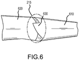
- one or more delta vortex generators attached to the leading edge of the wing can also be employed to generate a strong vortex at a certain position along the wing span that are operable to restrict the stall to the inboard sections of the wing.
- a vortex generator is illustrated, for example in Figure 6 .
- the delta vortex generator 630 described is incorporated into the cuff, enhancing the effectiveness of the cuff for producing a focused vortex.
- the vortex generator 630 extends the leading edge of the outboard section 610 overlapping the inboard section 620 of the wing. At high angles of attack, airflow passes from beneath the outboard section 610 and around the cuff root and vortex generator.
- the vortex generator 630 energizes the flow, enhancing the creation of an aerodynamic fence.
- Another aspect of the present invention is the inclusion of vortex generators on the wing, above the leading edge, outboard of the cuff.
- the vortex generators add energy to the airflow, reducing boundary layer thickness and enabling the airflow to remain attached to the wing to higher angle of attack.
- Another feature of the present invention is not only the incorporation of a plurality of varied airfoils across the span of the wing, but a wing twist that places the wing root at a higher angle of attack than the wing tip. As the angle of attack of the wing is increased, the wing root will experience a higher local angle of attack than the wing tip and stall first. While the wing twist and the implementation of various airfoils continually varies from root to tip, there is a discrete change at the cuff creating a fence.
- the tail area and span are modified in concert with modifications of the wing to enhance stability and spin resistance.
- the span of the tail is increased and a horizontal tail tip with an increased sweep is added.
- the various combinations of airfoil selection, wing twist, stall strips, wing cuff and vortex generators are fashioned in consideration with the interaction of airflow around the fuselage of an amphibious aircraft.
- the airflow over the inboard sections of the wing area is affected by the airflow over the fuselage and sponson or sea wing.
- the forward position of the sponson or sea wing with respect to the leading edge of the wing acts, in high angle of attack situations, to direct the airflow, reducing the wing's effective angle of attack and therefore its lift.
- the local angle if incidence of the wing in the area of the sponson or seawing can be increased to make up for the seawing-induced loss of lift, thereby promoting the desirable root-first wing stall progression.
- the aircraft develops a stable and isolated stall cell confined to the inboard sections of the wing.
- a significant portion of the outboard section of the wing including a significant portion of both ailerons, retain attached flow.
- the remaining inboard sections of the wing experience either reverse or lateral flow.
- the stall cells remain confined. This confinement of the stall cell promotes spin resistant behavior.
- the present invention provides a spin resistant configuration.
- each individual feature interacts synergistically to create a stable stall cell that is trapped on the inboard portions of the wing.
- the stable and trapped stall cell combined with an emmpanage that remains effective provides the pilot with adequate roll, pitch and yaw control, despite the fact that the wing is in a full stall, to resist entry into a spin.
- flight tests have demonstrated that the stall cell is so well confined that even with full aft controls and full deflection of the rudder, thus inducing yaw into the stall condition, the aircraft remains completely controllable.
- the spin resistant configuration comprises:
- spin resistant configuration for an aircraft can include:
Landscapes
- Engineering & Computer Science (AREA)
- Aviation & Aerospace Engineering (AREA)
- Mechanical Engineering (AREA)
- Structures Of Non-Positive Displacement Pumps (AREA)
- Tires In General (AREA)
- Toys (AREA)
- Aerodynamic Tests, Hydrodynamic Tests, Wind Tunnels, And Water Tanks (AREA)
Claims (12)
- Ein Fluggerät, das ausgebildet ist, um trudelresistent zu sein, wobei das besagte Fluggerät umfasst:einen Rumpf; undeinen Flügel, wobei der Flügel einen ersten Bereich (220) benachbart zu dem Rumpf und einen zweiten Bereich (210) benachbart zu einer Flügelspitze, wobei der erste Bereich an den zweiten Bereich angrenzend ist, eine variable Flügelwindung (510-550) derart, dass ein Flügelspitzeneinstellwinkel geringer ist als ein Flügelwurzeleinstellwinkel, und einen oder mehrere Strömungsabrissstreifen (320, 410, 420) einschließt, die an einer Anströmkante des ersten Bereiches des Flügels angebracht sind und eingerichtet sind, an der Anströmkante des Flügels ausgerichtet zu sein;eine Flügelstulpe (215), die zwischen dem ersten Bereich und dem zweiten Bereich angeordnet ist und eingerichtet ist, eine aerodynamische Grenze (260) zwischen dem ersten Bereich und dem zweiten Bereich bei hohen Anstellwinkeln zu bilden, um eine Strömungsabrisszelle (240) zu beschränken, innerhalb des ersten Bereiches und getrennt von Flugsteuerungen innerhalb des zweiten Bereiches zu bleiben.
- Das Fluggerät wie in Anspruch 1 definiert, wobei die Stulpe (215) einen Dreieckswirbelerzeuger (630) einschließt.
- Das Fluggerät wie in Anspruch 1 definiert, wobei der erste Bereich (220) eine oder mehrere Strömungsabrissstreifen (320, 410, 420), die mit einer Anströmkante des Flügels in Zusammenhang stehen, einschließt.
- Das Fluggerät wie in Anspruch 1 definiert, wobei der zweite Bereich Wirbelerzeuger (630) einschließt.
- Das Fluggerät wie in Anspruch 1 definiert, wobei die Flügelspitze vorwärts gepfeilt ist.
- Das Fluggerät wie in Anspruch 1 definiert, wobei das Fluggerät ein amphibisches Fluggerät ist, das Schwimmer einschließt.
- Das Fluggerät wie in Anspruch 6 definiert, wobei bei hohen Anstellwinkeln die Schwimmer einen effektiven Anstellwinkel des Flügels nahe dem Rumpf reduzieren.
- Ein System für eine trudelresistente Konfiguration in einem Fluggerät, wobei das System umfasst:einen Flügel mit Rumpf und einer Flügelspitze, wobei der Flügel einen ersten Bereich (220) nahe der Flügelwurzel und einen zweiten Bereich (210) nahe der Flügelspitze einschließt und wobei der erste Bereich und der zweite Bereich entlang einer zusammenhängenden Grenze angrenzend sind, einer variablen Flügelwindung (510-550) derart, dass ein Flügelspitzeneinstellwinkel geringer ist als ein Flügelwurzeleinstellwinkel, und einem oder mehreren Strömungsabrissstreifen (320, 410, 420), die an einer Anströmkante des ersten Bereiches des Flügels angebracht sind und eingerichtet sind, an der Anströmkante des Flügels ausgerichtet zu sein;und eine Anströmkantendiskontinuität (215), die bei hohen Anstellwinkeln betriebsbereit ist, ein aerodynamisches Hindernis (260) entlang der zusammenhängenden Grenze zu bilden, das eine Strömungsabrisszelle (240) isoliert, innerhalb des ersten Bereiches getrennt von irgendwelchen Steueroberflächen in dem zweiten Bereich zu bleiben.
- Das System für eine trudelresistente Konfiguration in dem Fluggerät nach Anspruch 8, wobei in Reaktion auf eine Strömungsabrisszelle, die sich innerhalb des ersten Bereiches entwickelt, Steueroberflächen des Fluggerätes betriebsbereit bleiben, um das Fluggerät zu steuern.
- Das System für eine trudelresistente Konfiguration in dem Fluggerät nach Anspruch 9, wobei Fluggerätsteueroberflächen von der Strömungsabrisszelle isoliert sind.
- Das System für eine trudelresistente Konfiguration in dem Fluggerät nach Anspruch 8, das weiterhin eine Vielzahl von Wirbelerzeugern (630), die mit dem zweiten Bereich in Zusammenhang stehen, umfasst.
- Das System für eine trudelresistente Konfiguration in dem Fluggerät nach Anspruch 8, wobei das Fluggerät ein amphibisches Fluggerät mit Schwimmern ist und wobei die Flügelwindung (510-550) an der Wurzel wegen einer effektiven Anstellwinkelreduktion wegen der Schwimmer erhöht ist.
Applications Claiming Priority (2)
| Application Number | Priority Date | Filing Date | Title |
|---|---|---|---|
| US201261674267P | 2012-07-20 | 2012-07-20 | |
| PCT/US2013/051355 WO2014074182A1 (en) | 2012-07-20 | 2013-07-19 | Spin resistant aircraft configuration |
Publications (2)
| Publication Number | Publication Date |
|---|---|
| EP2874873A1 EP2874873A1 (de) | 2015-05-27 |
| EP2874873B1 true EP2874873B1 (de) | 2016-12-14 |
Family
ID=49945732
Family Applications (1)
| Application Number | Title | Priority Date | Filing Date |
|---|---|---|---|
| EP13827053.3A Active EP2874873B1 (de) | 2012-07-20 | 2013-07-19 | Trudelresistente flugzeugkonfiguration |
Country Status (10)
| Country | Link |
|---|---|
| US (3) | US9327828B2 (de) |
| EP (1) | EP2874873B1 (de) |
| CN (1) | CN104203748B (de) |
| AU (2) | AU2013341766B2 (de) |
| BR (1) | BR112015000821B1 (de) |
| CA (1) | CA2878905C (de) |
| ES (1) | ES2620628T3 (de) |
| MX (1) | MX363459B (de) |
| RU (1) | RU2640669C2 (de) |
| WO (1) | WO2014074182A1 (de) |
Families Citing this family (13)
| Publication number | Priority date | Publication date | Assignee | Title |
|---|---|---|---|---|
| AU2013341766B2 (en) * | 2012-07-20 | 2016-06-09 | SG Investment America, Inc. | Spin resistant aircraft configuration |
| US8939410B2 (en) * | 2013-02-06 | 2015-01-27 | Reginald J Exton | Boundary layer flow disruptors for delaying transition to turbulent flow |
| US10239606B2 (en) * | 2013-12-04 | 2019-03-26 | Tamarack Aerospace Group, Inc. | Airflow interrupting devices |
| US20150361951A1 (en) * | 2014-06-17 | 2015-12-17 | Siemens Energy, Inc. | Pressure side stall strip for wind turbine blade |
| FR3039129B1 (fr) * | 2015-07-20 | 2017-07-07 | Airbus Helicopters | Ailette de fuselage d'aeronef et aeronef associe |
| DK178874B1 (en) * | 2015-08-19 | 2017-04-18 | Envision Energy (Jiangsu) Co Ltd | Wind turbine blade with tripping device and method thereof |
| GB201805279D0 (en) * | 2018-03-29 | 2018-05-16 | Archangel Lightworks Ltd | Wing tips and wing tips construction design methods |
| DE102019202354A1 (de) * | 2019-02-21 | 2020-08-27 | HORTEN Aircraft GmbH | Schwanzloses Flugzeug |
| CN110920866A (zh) * | 2019-11-18 | 2020-03-27 | 北京航空航天大学 | 一种通过机翼扰流板抑制飞机摇滚运动的方法 |
| US11440644B2 (en) * | 2020-02-21 | 2022-09-13 | Textron Innovations Inc. | Download reducing winglets for aircraft having a rotor producing downwash and method of operating the same |
| CN111924086B (zh) * | 2020-07-07 | 2021-12-10 | 北京机电工程研究所 | 一种记忆合金驱动的可变形机构 |
| US11869877B2 (en) | 2021-08-06 | 2024-01-09 | Sandisk Technologies Llc | Bonded assembly including inter-die via structures and methods for making the same |
| NL2030268B1 (en) * | 2021-12-23 | 2023-06-29 | Deltaquad B V | Fixed-wing aircraft |
Family Cites Families (28)
| Publication number | Priority date | Publication date | Assignee | Title |
|---|---|---|---|---|
| GB407009A (en) * | 1932-09-07 | 1934-03-07 | Vickers Aviat Ltd | Improvements in or connected with cantilever wings for aircraft |
| US2210642A (en) * | 1938-05-27 | 1940-08-06 | Stephen W Thompson | Aircraft |
| US2369832A (en) * | 1942-12-14 | 1945-02-20 | Cons Vultee Aircraft Corp | Airplane aileron system |
| US2964271A (en) * | 1956-12-17 | 1960-12-13 | Theodore R Strawn | Amphibian aircraft |
| US3370810A (en) | 1966-02-01 | 1968-02-27 | Mc Donnell Douglas Corp | Stall control device for swept wings |
| US4323209A (en) * | 1977-07-18 | 1982-04-06 | Thompson Roger A | Counter-rotating vortices generator for an aircraft wing |
| US4334658A (en) * | 1979-04-06 | 1982-06-15 | Mackenzie Sprague B | Stalling aerodynamics of the Cessna models 150 and 152 series aircraft |
| US4354648A (en) * | 1980-02-06 | 1982-10-19 | Gates Learjet Corporation | Airstream modification device for airfoils |
| US4334654A (en) | 1980-05-13 | 1982-06-15 | Akzona, Incorporated | Apparatus and method for controlling the tension on a yarn bundle withdrawn from a mass of compacted yarn |
| SU1840516A1 (ru) * | 1983-03-21 | 2007-05-27 | Федеральное государственное унитарное предприятие "Центральный аэрогидродинамический институт им. профессора Н.Е. Жуковского" | Летательный аппарат |
| US4706910A (en) * | 1984-12-27 | 1987-11-17 | The United States Of America As Represented By The Administrator Of The National Aeronautics And Space Administration | Combined riblet and lebu drag reduction system |
| DE3521329A1 (de) * | 1985-06-14 | 1986-12-18 | Messerschmitt-Bölkow-Blohm GmbH, 8012 Ottobrunn | Wirbelgeneratoren- und grenzschichtabweiseranordnung |
| US4776542A (en) * | 1987-05-27 | 1988-10-11 | Vigyan Research Associates, Inc. | Aircraft stall-spin entry deterrent system |
| US5253828A (en) * | 1992-07-17 | 1993-10-19 | The Board Of Regents Of The University Of Oklahoma | Concealable flap-actuated vortex generator |
| US5634613A (en) * | 1994-07-18 | 1997-06-03 | Mccarthy; Peter T. | Tip vortex generation technology for creating a lift enhancing and drag reducing upwash effect |
| US5598990A (en) * | 1994-12-15 | 1997-02-04 | University Of Kansas Center For Research Inc. | Supersonic vortex generator |
| US5772155A (en) * | 1996-06-01 | 1998-06-30 | Nowak; Dieter K. | Aircraft wing flaps |
| ITMI20012170A1 (it) * | 2001-10-18 | 2003-04-18 | Aermacchi S P A | Configurazione velivolo a prestazioni aerodinamiche migliorate |
| US6578798B1 (en) * | 2002-04-08 | 2003-06-17 | Faruk Dizdarevic | Airlifting surface division |
| US7234914B2 (en) * | 2002-11-12 | 2007-06-26 | Continum Dynamics, Inc. | Apparatus and method for enhancing lift produced by an airfoil |
| US7503527B1 (en) * | 2004-01-22 | 2009-03-17 | Fairchild Mark D | Flight control method and apparatus to produce induced yaw |
| DE102004045732A1 (de) * | 2004-09-21 | 2006-03-30 | Airbus Deutschland Gmbh | Flugzeug mit Flügeln, deren maximaler Auftrieb durch steuerbare Flügelkomponenten veränderbar ist |
| US7537182B2 (en) * | 2004-09-23 | 2009-05-26 | The United States Of America As Represented By The Administrator Of The National Aeronautics And Space Administration | Simultaneous multiple-location separation control |
| US8152109B2 (en) * | 2007-11-29 | 2012-04-10 | Silich Bert A | Method and system for controlling fluid flow in relation to a foil and harnessing energy therefrom |
| US20100123047A1 (en) * | 2008-11-14 | 2010-05-20 | Williams Aerospace, Inc. | Blended Wing Body Unmanned Aerial Vehicle |
| TWI482292B (zh) | 2009-11-24 | 2015-04-21 | Ind Tech Res Inst | 量子點染料敏化太陽電池 |
| JP2011135058A (ja) | 2009-11-30 | 2011-07-07 | Honda Motor Co Ltd | 太陽電池素子、カラーセンサ、ならびに発光素子及び受光素子の製造方法 |
| AU2013341766B2 (en) * | 2012-07-20 | 2016-06-09 | SG Investment America, Inc. | Spin resistant aircraft configuration |
-
2013
- 2013-07-19 AU AU2013341766A patent/AU2013341766B2/en active Active
- 2013-07-19 MX MX2015000626A patent/MX363459B/es unknown
- 2013-07-19 EP EP13827053.3A patent/EP2874873B1/de active Active
- 2013-07-19 CN CN201380003800.2A patent/CN104203748B/zh active Active
- 2013-07-19 CA CA2878905A patent/CA2878905C/en active Active
- 2013-07-19 US US13/946,572 patent/US9327828B2/en active Active
- 2013-07-19 ES ES13827053.3T patent/ES2620628T3/es active Active
- 2013-07-19 RU RU2014151868A patent/RU2640669C2/ru active
- 2013-07-19 WO PCT/US2013/051355 patent/WO2014074182A1/en not_active Ceased
- 2013-07-19 BR BR112015000821-6A patent/BR112015000821B1/pt active IP Right Grant
-
2016
- 2016-04-05 US US15/090,945 patent/US9926071B2/en active Active
- 2016-09-09 AU AU2016225939A patent/AU2016225939B2/en active Active
-
2018
- 2018-02-09 US US15/892,638 patent/US10723444B2/en active Active
Non-Patent Citations (1)
| Title |
|---|
| None * |
Also Published As
| Publication number | Publication date |
|---|---|
| MX2015000626A (es) | 2015-04-14 |
| US20170021916A1 (en) | 2017-01-26 |
| AU2013341766A1 (en) | 2015-01-22 |
| CA2878905C (en) | 2020-07-07 |
| RU2640669C2 (ru) | 2018-01-11 |
| RU2014151868A (ru) | 2016-09-10 |
| WO2014074182A1 (en) | 2014-05-15 |
| CN104203748A (zh) | 2014-12-10 |
| US10723444B2 (en) | 2020-07-28 |
| BR112015000821A2 (pt) | 2019-11-05 |
| US9926071B2 (en) | 2018-03-27 |
| US9327828B2 (en) | 2016-05-03 |
| ES2620628T3 (es) | 2017-06-29 |
| US20140021302A1 (en) | 2014-01-23 |
| CN104203748B (zh) | 2016-08-24 |
| MX363459B (es) | 2019-03-25 |
| CA2878905A1 (en) | 2014-05-15 |
| AU2016225939B2 (en) | 2018-04-05 |
| AU2016225939A1 (en) | 2016-09-29 |
| US20180178903A1 (en) | 2018-06-28 |
| EP2874873A1 (de) | 2015-05-27 |
| AU2013341766B2 (en) | 2016-06-09 |
| BR112015000821B1 (pt) | 2022-01-25 |
Similar Documents
| Publication | Publication Date | Title |
|---|---|---|
| EP2874873B1 (de) | Trudelresistente flugzeugkonfiguration | |
| US8657226B1 (en) | Efficient control and stall prevention in advanced configuration aircraft | |
| US9545993B2 (en) | Aircraft stability and efficient control through induced drag reduction | |
| EP3202661B1 (de) | Leistungssteigerndes wingletsystem und verfahren | |
| US8820673B2 (en) | Rotary-wing and fixed-wing aircraft | |
| CN118928758A (zh) | 具有后旋翼和t型尾翼的固定翼飞机 | |
| US10562626B2 (en) | Tandem wing aircraft with variable lift and enhanced safety | |
| US4261533A (en) | All-axis control of aircraft in ultra deep stall | |
| WO2013037379A9 (ru) | Фюзеляж и способ уменьшения сопротивления | |
| RU2668000C1 (ru) | Самолет-амфибия схемы "летающее крыло" | |
| US9038943B1 (en) | Safety aileron system | |
| CN110770121B (zh) | 飞行器 | |
| RU2667410C1 (ru) | Аэродинамическая поверхность и планер летательного аппарата | |
| US20110180672A1 (en) | Airplane with aerodynamic stall-prevention layout and pertinent longitudinal stability arrangement | |
| US20090266938A1 (en) | Method and device for an aircraft buffet reduction | |
| CN221214604U (zh) | 一种水平尾翼内置旋翼的倾转旋翼无人vtol飞行器 | |
| US10654556B2 (en) | VTOL aircraft with wings | |
| Stoop et al. | Stall shield devices, an innovative approach to stall prevention? | |
| CN107697282A (zh) | 一种新型概念垂直起降飞行器及其控制方法 | |
| RU2572507C1 (ru) | Учебный самолет | |
| Basri et al. | The Effect of Elevons Deflection to Aerodynamic Coefficients of A Tail-less Blended Wing-Body Planform | |
| IL226119A (en) | Wing cut, wings and aircraft | |
| Stoop et al. | Design of an innovative stall recovery device | |
| Fonternel | Development of the Rooivalk horizontal and vertical stabolizers |
Legal Events
| Date | Code | Title | Description |
|---|---|---|---|
| PUAI | Public reference made under article 153(3) epc to a published international application that has entered the european phase |
Free format text: ORIGINAL CODE: 0009012 |
|
| 17P | Request for examination filed |
Effective date: 20141218 |
|
| AK | Designated contracting states |
Kind code of ref document: A1 Designated state(s): AL AT BE BG CH CY CZ DE DK EE ES FI FR GB GR HR HU IE IS IT LI LT LU LV MC MK MT NL NO PL PT RO RS SE SI SK SM TR |
|
| AX | Request for extension of the european patent |
Extension state: BA ME |
|
| DAX | Request for extension of the european patent (deleted) | ||
| GRAP | Despatch of communication of intention to grant a patent |
Free format text: ORIGINAL CODE: EPIDOSNIGR1 |
|
| INTG | Intention to grant announced |
Effective date: 20160706 |
|
| GRAS | Grant fee paid |
Free format text: ORIGINAL CODE: EPIDOSNIGR3 |
|
| GRAA | (expected) grant |
Free format text: ORIGINAL CODE: 0009210 |
|
| AK | Designated contracting states |
Kind code of ref document: B1 Designated state(s): AL AT BE BG CH CY CZ DE DK EE ES FI FR GB GR HR HU IE IS IT LI LT LU LV MC MK MT NL NO PL PT RO RS SE SI SK SM TR |
|
| REG | Reference to a national code |
Ref country code: GB Ref legal event code: FG4D |
|
| REG | Reference to a national code |
Ref country code: CH Ref legal event code: EP |
|
| REG | Reference to a national code |
Ref country code: IE Ref legal event code: FG4D |
|
| REG | Reference to a national code |
Ref country code: AT Ref legal event code: REF Ref document number: 853304 Country of ref document: AT Kind code of ref document: T Effective date: 20170115 |
|
| REG | Reference to a national code |
Ref country code: DE Ref legal event code: R096 Ref document number: 602013015467 Country of ref document: DE |
|
| PG25 | Lapsed in a contracting state [announced via postgrant information from national office to epo] |
Ref country code: LV Free format text: LAPSE BECAUSE OF FAILURE TO SUBMIT A TRANSLATION OF THE DESCRIPTION OR TO PAY THE FEE WITHIN THE PRESCRIBED TIME-LIMIT Effective date: 20161214 |
|
| REG | Reference to a national code |
Ref country code: LT Ref legal event code: MG4D |
|
| REG | Reference to a national code |
Ref country code: NL Ref legal event code: MP Effective date: 20161214 |
|
| PG25 | Lapsed in a contracting state [announced via postgrant information from national office to epo] |
Ref country code: NO Free format text: LAPSE BECAUSE OF FAILURE TO SUBMIT A TRANSLATION OF THE DESCRIPTION OR TO PAY THE FEE WITHIN THE PRESCRIBED TIME-LIMIT Effective date: 20170314 Ref country code: SE Free format text: LAPSE BECAUSE OF FAILURE TO SUBMIT A TRANSLATION OF THE DESCRIPTION OR TO PAY THE FEE WITHIN THE PRESCRIBED TIME-LIMIT Effective date: 20161214 Ref country code: LT Free format text: LAPSE BECAUSE OF FAILURE TO SUBMIT A TRANSLATION OF THE DESCRIPTION OR TO PAY THE FEE WITHIN THE PRESCRIBED TIME-LIMIT Effective date: 20161214 |
|
| REG | Reference to a national code |
Ref country code: AT Ref legal event code: MK05 Ref document number: 853304 Country of ref document: AT Kind code of ref document: T Effective date: 20161214 |
|
| PG25 | Lapsed in a contracting state [announced via postgrant information from national office to epo] |
Ref country code: RS Free format text: LAPSE BECAUSE OF FAILURE TO SUBMIT A TRANSLATION OF THE DESCRIPTION OR TO PAY THE FEE WITHIN THE PRESCRIBED TIME-LIMIT Effective date: 20161214 Ref country code: FI Free format text: LAPSE BECAUSE OF FAILURE TO SUBMIT A TRANSLATION OF THE DESCRIPTION OR TO PAY THE FEE WITHIN THE PRESCRIBED TIME-LIMIT Effective date: 20161214 Ref country code: HR Free format text: LAPSE BECAUSE OF FAILURE TO SUBMIT A TRANSLATION OF THE DESCRIPTION OR TO PAY THE FEE WITHIN THE PRESCRIBED TIME-LIMIT Effective date: 20161214 |
|
| REG | Reference to a national code |
Ref country code: ES Ref legal event code: FG2A Ref document number: 2620628 Country of ref document: ES Kind code of ref document: T3 Effective date: 20170629 |
|
| PG25 | Lapsed in a contracting state [announced via postgrant information from national office to epo] |
Ref country code: NL Free format text: LAPSE BECAUSE OF FAILURE TO SUBMIT A TRANSLATION OF THE DESCRIPTION OR TO PAY THE FEE WITHIN THE PRESCRIBED TIME-LIMIT Effective date: 20161214 |
|
| REG | Reference to a national code |
Ref country code: FR Ref legal event code: PLFP Year of fee payment: 5 |
|
| PG25 | Lapsed in a contracting state [announced via postgrant information from national office to epo] |
Ref country code: RO Free format text: LAPSE BECAUSE OF FAILURE TO SUBMIT A TRANSLATION OF THE DESCRIPTION OR TO PAY THE FEE WITHIN THE PRESCRIBED TIME-LIMIT Effective date: 20161214 Ref country code: SK Free format text: LAPSE BECAUSE OF FAILURE TO SUBMIT A TRANSLATION OF THE DESCRIPTION OR TO PAY THE FEE WITHIN THE PRESCRIBED TIME-LIMIT Effective date: 20161214 Ref country code: IS Free format text: LAPSE BECAUSE OF FAILURE TO SUBMIT A TRANSLATION OF THE DESCRIPTION OR TO PAY THE FEE WITHIN THE PRESCRIBED TIME-LIMIT Effective date: 20170414 Ref country code: EE Free format text: LAPSE BECAUSE OF FAILURE TO SUBMIT A TRANSLATION OF THE DESCRIPTION OR TO PAY THE FEE WITHIN THE PRESCRIBED TIME-LIMIT Effective date: 20161214 |
|
| REG | Reference to a national code |
Ref country code: GR Ref legal event code: EP Ref document number: 20170400784 Country of ref document: GR Effective date: 20170804 |
|
| PG25 | Lapsed in a contracting state [announced via postgrant information from national office to epo] |
Ref country code: PL Free format text: LAPSE BECAUSE OF FAILURE TO SUBMIT A TRANSLATION OF THE DESCRIPTION OR TO PAY THE FEE WITHIN THE PRESCRIBED TIME-LIMIT Effective date: 20161214 Ref country code: PT Free format text: LAPSE BECAUSE OF FAILURE TO SUBMIT A TRANSLATION OF THE DESCRIPTION OR TO PAY THE FEE WITHIN THE PRESCRIBED TIME-LIMIT Effective date: 20170414 Ref country code: BE Free format text: LAPSE BECAUSE OF FAILURE TO SUBMIT A TRANSLATION OF THE DESCRIPTION OR TO PAY THE FEE WITHIN THE PRESCRIBED TIME-LIMIT Effective date: 20161214 Ref country code: BG Free format text: LAPSE BECAUSE OF FAILURE TO SUBMIT A TRANSLATION OF THE DESCRIPTION OR TO PAY THE FEE WITHIN THE PRESCRIBED TIME-LIMIT Effective date: 20170314 Ref country code: SM Free format text: LAPSE BECAUSE OF FAILURE TO SUBMIT A TRANSLATION OF THE DESCRIPTION OR TO PAY THE FEE WITHIN THE PRESCRIBED TIME-LIMIT Effective date: 20161214 Ref country code: AT Free format text: LAPSE BECAUSE OF FAILURE TO SUBMIT A TRANSLATION OF THE DESCRIPTION OR TO PAY THE FEE WITHIN THE PRESCRIBED TIME-LIMIT Effective date: 20161214 |
|
| REG | Reference to a national code |
Ref country code: DE Ref legal event code: R097 Ref document number: 602013015467 Country of ref document: DE |
|
| PLBE | No opposition filed within time limit |
Free format text: ORIGINAL CODE: 0009261 |
|
| STAA | Information on the status of an ep patent application or granted ep patent |
Free format text: STATUS: NO OPPOSITION FILED WITHIN TIME LIMIT |
|
| 26N | No opposition filed |
Effective date: 20170915 |
|
| PG25 | Lapsed in a contracting state [announced via postgrant information from national office to epo] |
Ref country code: DK Free format text: LAPSE BECAUSE OF FAILURE TO SUBMIT A TRANSLATION OF THE DESCRIPTION OR TO PAY THE FEE WITHIN THE PRESCRIBED TIME-LIMIT Effective date: 20161214 |
|
| PG25 | Lapsed in a contracting state [announced via postgrant information from national office to epo] |
Ref country code: SI Free format text: LAPSE BECAUSE OF FAILURE TO SUBMIT A TRANSLATION OF THE DESCRIPTION OR TO PAY THE FEE WITHIN THE PRESCRIBED TIME-LIMIT Effective date: 20161214 |
|
| REG | Reference to a national code |
Ref country code: CH Ref legal event code: PL |
|
| REG | Reference to a national code |
Ref country code: IE Ref legal event code: MM4A |
|
| PG25 | Lapsed in a contracting state [announced via postgrant information from national office to epo] |
Ref country code: IE Free format text: LAPSE BECAUSE OF NON-PAYMENT OF DUE FEES Effective date: 20170719 Ref country code: LI Free format text: LAPSE BECAUSE OF NON-PAYMENT OF DUE FEES Effective date: 20170731 Ref country code: CH Free format text: LAPSE BECAUSE OF NON-PAYMENT OF DUE FEES Effective date: 20170731 |
|
| PG25 | Lapsed in a contracting state [announced via postgrant information from national office to epo] |
Ref country code: LU Free format text: LAPSE BECAUSE OF NON-PAYMENT OF DUE FEES Effective date: 20170719 |
|
| REG | Reference to a national code |
Ref country code: FR Ref legal event code: PLFP Year of fee payment: 6 |
|
| PG25 | Lapsed in a contracting state [announced via postgrant information from national office to epo] |
Ref country code: MT Free format text: LAPSE BECAUSE OF NON-PAYMENT OF DUE FEES Effective date: 20170719 |
|
| PG25 | Lapsed in a contracting state [announced via postgrant information from national office to epo] |
Ref country code: HU Free format text: LAPSE BECAUSE OF FAILURE TO SUBMIT A TRANSLATION OF THE DESCRIPTION OR TO PAY THE FEE WITHIN THE PRESCRIBED TIME-LIMIT; INVALID AB INITIO Effective date: 20130719 Ref country code: MC Free format text: LAPSE BECAUSE OF FAILURE TO SUBMIT A TRANSLATION OF THE DESCRIPTION OR TO PAY THE FEE WITHIN THE PRESCRIBED TIME-LIMIT Effective date: 20161214 |
|
| PG25 | Lapsed in a contracting state [announced via postgrant information from national office to epo] |
Ref country code: CY Free format text: LAPSE BECAUSE OF FAILURE TO SUBMIT A TRANSLATION OF THE DESCRIPTION OR TO PAY THE FEE WITHIN THE PRESCRIBED TIME-LIMIT Effective date: 20161214 |
|
| PG25 | Lapsed in a contracting state [announced via postgrant information from national office to epo] |
Ref country code: MK Free format text: LAPSE BECAUSE OF FAILURE TO SUBMIT A TRANSLATION OF THE DESCRIPTION OR TO PAY THE FEE WITHIN THE PRESCRIBED TIME-LIMIT Effective date: 20161214 |
|
| PG25 | Lapsed in a contracting state [announced via postgrant information from national office to epo] |
Ref country code: AL Free format text: LAPSE BECAUSE OF FAILURE TO SUBMIT A TRANSLATION OF THE DESCRIPTION OR TO PAY THE FEE WITHIN THE PRESCRIBED TIME-LIMIT Effective date: 20161214 |
|
| REG | Reference to a national code |
Ref country code: DE Ref legal event code: R082 Ref document number: 602013015467 Country of ref document: DE Representative=s name: RAU, SCHNECK & HUEBNER PATENTANWAELTE RECHTSAN, DE Ref country code: DE Ref legal event code: R081 Ref document number: 602013015467 Country of ref document: DE Owner name: SG INVESTMENT AMERICA, INC., VACAVILLE, US Free format text: FORMER OWNER: ICON AIRCRAFT, INC., LOS ANGELES, CALIF., US |
|
| REG | Reference to a national code |
Ref country code: GB Ref legal event code: 732E Free format text: REGISTERED BETWEEN 20250227 AND 20250305 |
|
| REG | Reference to a national code |
Ref country code: ES Ref legal event code: PC2A Owner name: SG LNVESTMENT AMERICA, LNC. Effective date: 20250519 |
|
| PGFP | Annual fee paid to national office [announced via postgrant information from national office to epo] |
Ref country code: ES Payment date: 20250819 Year of fee payment: 13 |
|
| PGFP | Annual fee paid to national office [announced via postgrant information from national office to epo] |
Ref country code: DE Payment date: 20250919 Year of fee payment: 13 |
|
| PGFP | Annual fee paid to national office [announced via postgrant information from national office to epo] |
Ref country code: GR Payment date: 20250721 Year of fee payment: 13 |
|
| PGFP | Annual fee paid to national office [announced via postgrant information from national office to epo] |
Ref country code: TR Payment date: 20250716 Year of fee payment: 13 Ref country code: IT Payment date: 20250731 Year of fee payment: 13 |
|
| PGFP | Annual fee paid to national office [announced via postgrant information from national office to epo] |
Ref country code: GB Payment date: 20250724 Year of fee payment: 13 |
|
| PGFP | Annual fee paid to national office [announced via postgrant information from national office to epo] |
Ref country code: FR Payment date: 20250723 Year of fee payment: 13 |
|
| PGFP | Annual fee paid to national office [announced via postgrant information from national office to epo] |
Ref country code: CZ Payment date: 20250710 Year of fee payment: 13 |