EP2874896B1 - Spill resistant disposable travel cup lid - Google Patents
Spill resistant disposable travel cup lid Download PDFInfo
- Publication number
- EP2874896B1 EP2874896B1 EP13819706.6A EP13819706A EP2874896B1 EP 2874896 B1 EP2874896 B1 EP 2874896B1 EP 13819706 A EP13819706 A EP 13819706A EP 2874896 B1 EP2874896 B1 EP 2874896B1
- Authority
- EP
- European Patent Office
- Prior art keywords
- drink
- lid
- chamber
- side wall
- orifice
- Prior art date
- Legal status (The legal status is an assumption and is not a legal conclusion. Google has not performed a legal analysis and makes no representation as to the accuracy of the status listed.)
- Active
Links
Images





Classifications
-
- B—PERFORMING OPERATIONS; TRANSPORTING
- B65—CONVEYING; PACKING; STORING; HANDLING THIN OR FILAMENTARY MATERIAL
- B65D—CONTAINERS FOR STORAGE OR TRANSPORT OF ARTICLES OR MATERIALS, e.g. BAGS, BARRELS, BOTTLES, BOXES, CANS, CARTONS, CRATES, DRUMS, JARS, TANKS, HOPPERS, FORWARDING CONTAINERS; ACCESSORIES, CLOSURES, OR FITTINGS THEREFOR; PACKAGING ELEMENTS; PACKAGES
- B65D43/00—Lids or covers for rigid or semi-rigid containers
- B65D43/02—Removable lids or covers
- B65D43/0202—Removable lids or covers without integral tamper element
- B65D43/0204—Removable lids or covers without integral tamper element secured by snapping over beads or projections
- B65D43/0212—Removable lids or covers without integral tamper element secured by snapping over beads or projections only on the outside, or a part turned to the outside, of the mouth
-
- B—PERFORMING OPERATIONS; TRANSPORTING
- B29—WORKING OF PLASTICS; WORKING OF SUBSTANCES IN A PLASTIC STATE IN GENERAL
- B29C—SHAPING OR JOINING OF PLASTICS; SHAPING OF MATERIAL IN A PLASTIC STATE, NOT OTHERWISE PROVIDED FOR; AFTER-TREATMENT OF THE SHAPED PRODUCTS, e.g. REPAIRING
- B29C51/00—Shaping by thermoforming, i.e. shaping sheets or sheet like preforms after heating, e.g. shaping sheets in matched moulds or by deep-drawing; Apparatus therefor
- B29C51/10—Forming by pressure difference, e.g. vacuum
-
- B—PERFORMING OPERATIONS; TRANSPORTING
- B29—WORKING OF PLASTICS; WORKING OF SUBSTANCES IN A PLASTIC STATE IN GENERAL
- B29C—SHAPING OR JOINING OF PLASTICS; SHAPING OF MATERIAL IN A PLASTIC STATE, NOT OTHERWISE PROVIDED FOR; AFTER-TREATMENT OF THE SHAPED PRODUCTS, e.g. REPAIRING
- B29C2791/00—Shaping characteristics in general
- B29C2791/004—Shaping under special conditions
- B29C2791/006—Using vacuum
-
- B—PERFORMING OPERATIONS; TRANSPORTING
- B29—WORKING OF PLASTICS; WORKING OF SUBSTANCES IN A PLASTIC STATE IN GENERAL
- B29L—INDEXING SCHEME ASSOCIATED WITH SUBCLASS B29C, RELATING TO PARTICULAR ARTICLES
- B29L2031/00—Other particular articles
- B29L2031/56—Stoppers or lids for bottles, jars, or the like, e.g. closures
- B29L2031/565—Stoppers or lids for bottles, jars, or the like, e.g. closures for containers
-
- B—PERFORMING OPERATIONS; TRANSPORTING
- B65—CONVEYING; PACKING; STORING; HANDLING THIN OR FILAMENTARY MATERIAL
- B65D—CONTAINERS FOR STORAGE OR TRANSPORT OF ARTICLES OR MATERIALS, e.g. BAGS, BARRELS, BOTTLES, BOXES, CANS, CARTONS, CRATES, DRUMS, JARS, TANKS, HOPPERS, FORWARDING CONTAINERS; ACCESSORIES, CLOSURES, OR FITTINGS THEREFOR; PACKAGING ELEMENTS; PACKAGES
- B65D2543/00—Lids or covers essentially for box-like containers
- B65D2543/00009—Details of lids or covers for rigid or semi-rigid containers
- B65D2543/00018—Overall construction of the lid
- B65D2543/00046—Drinking-through lids
-
- B—PERFORMING OPERATIONS; TRANSPORTING
- B65—CONVEYING; PACKING; STORING; HANDLING THIN OR FILAMENTARY MATERIAL
- B65D—CONTAINERS FOR STORAGE OR TRANSPORT OF ARTICLES OR MATERIALS, e.g. BAGS, BARRELS, BOTTLES, BOXES, CANS, CARTONS, CRATES, DRUMS, JARS, TANKS, HOPPERS, FORWARDING CONTAINERS; ACCESSORIES, CLOSURES, OR FITTINGS THEREFOR; PACKAGING ELEMENTS; PACKAGES
- B65D2543/00—Lids or covers essentially for box-like containers
- B65D2543/00009—Details of lids or covers for rigid or semi-rigid containers
- B65D2543/00018—Overall construction of the lid
- B65D2543/00064—Shape of the outer periphery
- B65D2543/00074—Shape of the outer periphery curved
- B65D2543/00092—Shape of the outer periphery curved circular
-
- B—PERFORMING OPERATIONS; TRANSPORTING
- B65—CONVEYING; PACKING; STORING; HANDLING THIN OR FILAMENTARY MATERIAL
- B65D—CONTAINERS FOR STORAGE OR TRANSPORT OF ARTICLES OR MATERIALS, e.g. BAGS, BARRELS, BOTTLES, BOXES, CANS, CARTONS, CRATES, DRUMS, JARS, TANKS, HOPPERS, FORWARDING CONTAINERS; ACCESSORIES, CLOSURES, OR FITTINGS THEREFOR; PACKAGING ELEMENTS; PACKAGES
- B65D2543/00—Lids or covers essentially for box-like containers
- B65D2543/00009—Details of lids or covers for rigid or semi-rigid containers
- B65D2543/00018—Overall construction of the lid
- B65D2543/00259—Materials used
- B65D2543/00296—Plastic
Definitions
- This disclosure relates to disposable lids for travel beverage cups and, more particularly, to disposable dome lids that may be placed over the lip of a beverage cup and that provide a drink-through opening near the perimeter of the lid's top surface so that a seal is formed by the user's mouth for easy drinking access to the beverage, especially while traveling.
- Prior disposable travel lids have an inherent shortcoming. When a relatively full cup is jostled as is often the case while moving about, the sloshing beverage is vulnerable to splashing out through the drink-through opening even when the hole is relatively small. Attempts have been made to address this concern by introducing devices to seal the drink-through opening when the beverage is not being consumed.
- previously presented disposable cup lids offer sealing methods that require manipulation to momentarily remove the sealing device so that the user is able to sip the beverage. While this methodology is practical if simply transporting the unconsumed beverage from one location to another, it is both cumbersome and impractical for occasional consumption while on the go.
- the present disclosure addresses this shortcoming by setting forth a novel embodiment having a passive integrated barrier within the disposable cup lid that adequately seals the drink-through opening while the beverage is not being consumed yet permits the consumer to drink from the cup in an enjoyable and satisfying manner.
- US Patent No. 20050173443 discloses a disposable dome lid according to the preamble of claim 1 and a method of forming said lid.
- This disclosure sets forth a number of novel features for a disposable dome lid, each of which decreases the likelihood of accidental spills as well as increasing the comfort to the user. These features can be implemented alone or in combination to maximize the overall benefits.
- a drink-through orifice that includes a flap configured to close off the drink-through opening while the user is not consuming the beverage.
- the flap yields and permits the beverage to flow through the drink-through orifice with sufficient ease to be a satisfying experience. The user generates the desired flow by gently "pulling" the beverage out from the cup.
- the likelihood of accidental spills is further reduced by: 1) recessing the required vent hole within a spill cavity; 2) improving the seal between the lid and the user's mouth; and 3) modifying the drink hole so froth foaming up through the lid is directed into a spill cavity rather than flowing over the cup's edge.
- a lid for a cup is provided according to claim 1.
- a method of forming and cutting a lid for a cup is provided according to claim 9.
- a disposable dome lid for mounting upon the substantially circular lip or rim of a disposable drinking cup.
- the lid includes a mounting portion that anchors upon the cup lip; an annular outer side wall portion sloping upwardly and radially inwardly from the mounting portion thereby providing a volume extension means within the lid.
- a top wall portion is formed at the top of the annular outer side wall portion enclosing the top of the annular outer side wall portion.
- a drink-through orifice is formed within the top wall portion and adjacent to the annular outer side wall portion, enabling drinking from the cup without removal of the lid and permitting the lips of a user drinking from the cup to encompass the drink-through orifice, with the lower lip of the user engaging with the annular outer side wall portion.
- the drink-through orifice includes a singular flap located within a drink-through chamber below the lid's top wall.
- the flap When the flap is in its relaxed position it prevents a drink-through opening and restricts sloshed liquid from exiting through the drink-through orifice. And when the flap is in its non-relaxed position it provides the drink-through opening and permits the beverage to flow through the drink-though orifice.
- the thermo-plastic material used in production is sufficiently thin and flexible to provide a flap or flaps that can open while the beverage is being consumed yet be sufficiently rigid to resist opening when confronted with a beverage that is sloshing within a generally upright cup. Understandably, other flap configurations may provide the intended result and the illustrated flap configurations should not be construed as the only possible configurations.
- the following embodiments further define the preferred flap within a drink-through orifice: (1) A drink-through orifice that closes off a drink-through opening by a restriction barrier in the form of at least one flap; (2) the previously described flap that is integrated within the material comprising the disposable cup lid, thereby eliminating the need for assembly; (3) the previously described flap that in its relaxed or non-deformed state, closes off the drink-through opening; (4) the previously described flap that is concealed by being positioned within a chamber below the drink-through orifice, wherein the flap is hidden from the casual observer and tactually out of reach from the consumer's lips or tongue; (5) the previously described flap within the chamber which, in its non-relaxed and deformed state, momentarily folds into the volume defined by the chamber, thereby exposing the drink-through opening and permitting the flow of beverage; (6) the previously described flap which incorporates a "living hinge” positioned at the bottom of the chamber, where the thermo-formed material is inherently significantly thinner; (7) the previously describe living hinge where its
- a disposable dome-shaped travel cup lid not because they are required in order for the flap's functionality, but because they further improve the disposable cup lid's resistance to accidental spills and enhance the user's comfort, including: (1) A spill cavity adjacent to the drink-through opening where an interior ridge formed by the boundary between these two features is recessed below the top wall thereby directing froth bubbling up through the drink-through opening to flow into the spill cavity; (2) a spill cavity including a small hole, for venting and possibly draining purposes, that is located near the lid's center where the level of a sloshing beverage remains relatively stable; (3) the previously described spill cavity further defined by an annular inner wall and an arcuate interior side wall, where the center of the arcuate interior side wall passes near the lid's center, thereby minimizing the size of the spill cavity while retaining its function; (4) the previously described spill cavity having a bottom wall that includes a narrow channel where, at its deepest portion, the previously describe vent hole
- Disposable cup lids are typically produced in large quantities by applying heat and pressure to form a thermo-plastic sheet that's placed over an array of singular molds, each of which forms a single lid. As a secondary production process, multiple lids are stamped out from each formed sheet. During this secondary process, desired holes and tear lines are also stamped into the lids. The flap or flaps set forth herein can be created during this stamping process.
- the present disclosure includes: (1) a process for vertically stamping within cavities formed in the previously describe dome lid with a singular vertical motion similar to that commonly used when stamping thermo-formed disposable cup dome lids, thereby simultaneously stamping flap, vent hole, and lid perimeter; (2) the previously described stamping method that enables a multiple of block dies used in stamping to self-align for simultaneous precision cutting of a multiple of lids from a single thermoplastic sheet.
- All of the independent embodiments in this disclosure can be applied individually or in combination to improve any disposable dome having a small drink-through orifice near the lid's perimeter.
- All disposable dome lids usually vacuum formed from thin-walled thermoplastic sheets, are designed to grip and seal upon an outwardly projecting ridge formed at the lip of disposable cups usually made from cardboard.
- Two methods for attaching disposable dome lids to cups have been described or illustrated in the art and are commonly used in practice.
- An original method referred to as the "ridge fit" provides an outwardly projecting annular ridge around the lid's apron that snaps into place when pushed over and mating with the cup's lip.
- the cup's lip has a slightly larger diameter than the lid's mounting ridge.
- a more recently developed method of attachment utilizes an inverted annular groove surrounding the lid's base, forming what is referred to as a "groove fit.”
- the lid is attached by "plugging" the cup's lip into the annular groove.
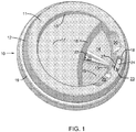
- FIGs 1 illustrates all of the preferred embodiments for a spill resistant disposable drink-through dome-shaped thin-walled cup lid 10.
- the lid 10 includes an outer top wall 11 bounded on its outer perimeter by an annular outer side wall 12 sloping downwardly and outwardly, and on its inner perimeter by an annular inner side wall 13 sloping downwardly and inwardly, with both perimeters being substantially concentric to one another.
- a spill cavity 14 is bounded by the annular inner side wall 13 and an arcuate interior side wall 16.
- the spill cavity 14 is further defined by a bottom wall 15, sloping gently upwardly and inwardly and terminating at the arcuate interior side wall 16.
- the inner top wall 17 is bound by the annular inner side wall 13 and is substantially planar.
- a drink-through orifice 18 is within the outer top wall 11 and aligns with the spill cavity 14.
- a mounting portion 19 is formed at or near the base of the annular outer side wall 12 in order to affix the lid 10 to the lip at the rim of a disposable drinking cup 31 shown in Figure 2 .
- the spill cavity 14 accommodates the user's upper lip by deepening the annular inner side wall 13 at the drink-through orifice 18.
- the inner top wall 17 is recessed slightly below the outer top wall 11 at its juncture with the arcuate interior side wall 16, and slopes downwardly and away from the spill cavity 14.
- the user's nose is accommodated by deepening the inner top wall 17 where the user's nose is most likely to make contact with lid 10.
- the user's lower lip is also accommodated by having the annular outer side wall 12 raised sufficiently so the user's lower lip generally clears the mounting portion 19.
- the user's comfort is further enhanced by providing a pair of beveled recesses 20 that slope downwardly and inwardly within the juncture of the outer top wall 11 and the annular inner side wall 13.
- the beveled recesses 20 are positioned on each side of the drink-through opening 29, generally at the two locations where the user's upper lip makes contact with the edge otherwise formed by the intersection of the annular inner side wall 13 and the outer top wall 11.
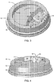
- FIG 3 illustrates a 3-dimensional drink-through orifice 18 that defines a drink-through opening 29.
- an interior ridge 27 is formed on the interior of side of the drink-through orifice 18 that can be recessed below the outer top wall 11, as best seen in Figure 4 .
- any froth bubbling up through the drink-though opening 29 is directed to flow into the spill cavity 14 instead of flowing down the side of a generally vertically positioned cup 31. Any fluid that happens to flow into the spill cavity 14, if not drained back into the cup through a vent hole 22, is conveniently consumed upon the user tilting the cup 31 to take the next sip of their beverage.
- the vent hole 22 is necessary for venting air into the cup 31 as the beverage is removed during consumption.
- the vent hole 22 is usually positioned on the outer top wall 11 or inner top wall 17 on the side opposite the drink-through orifice 18. By placing the vent hole 22 on either of the top walls 11 or 17, the vent hole 22, even though small, is exposed to potential spills from fluid dribbling out and running down the side of the cup 31. In its preferred configuration, the vent hole 22 is relocated within the spill cavity 14 as shown in Figures 1 , 3 and 10 . Any beverage that does happen to eject out through the vent hole 22 will be captured within the spill cavity 14.
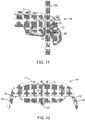
- FIGS 1 , 3 and 10 illustrate a channel 21 within the bottom wall 15 of the spill cavity 14.
- the vent hole 22 is shielded from being blocked by the user's upper lip during consumption.
- the vent hole 22 is now able to be increased in size to also serve as a drain for the spill cavity 14.
- the channel 21 is radially aligned with the arcuate interior side wall 16 and centered with the drink-through orifice 18, as shown in Figure 10.
- Figures 9 and 12 illustrate how the channel 21 can be formed sufficiently deep and narrow at the location of the vent hole 22 to prevent the user's upper lip from contacting the bottom of the channel 21, thereby blocking the vent hole 22.
- an orifice side wall 25 extends downwardly and inwardly from a perimeter of the drink-though orifice 18 and encloses on itself to form a chamber 23.
- the perimeter of the drink-through orifice 18 is defined by a pair of parallel linear edges connected by a pair of opposing semi-circular edges.
- the orifice side wall 25 forms a pair of opposing planar surfaces connected by a pair of opposing arcuate surfaces.
- the base of the chamber 23 is directly below and aligned with the drink-through orifice 18 as best seen in top views Figures 5A-5B and 10 .
- a flap or flaps 24 is formed by cutting into the base of the chamber 23, which in its preferred configuration is generally planar and horizontal.
- the drink-through orifice 18 is closed off thereby restricting sloshed liquid from exiting.
- the flap 24 is in its non-relaxed position, as shown in Figures 7 and 8 , the resulting drink-through opening 29 permits the beverage to flow through the drink-though orifice 18.
- the drink-through orifice 18 remains visually integrated within the dome cup lid 10 by preserving the curvature of the outer and inner side walls 12 and 13, and by preserving the height of the outer top wall 11 surrounding the drink-through orifice 18.
- the flap 24 is created by stamping a cut line into the base of the chamber 23 using die cutting methods adaptable to the industry.
- the flap 24 preferably follows the contour of the base of the orifice side wall 25 in order to maximize its size and resulting flow of beverage.
- the flap 24 is formed by cutting only partially around the perimeter with the uncut portion becoming a hinge portion 26, referred to as a "living hinge", and is preferably along one of the two linear edges within the base of the chamber 23.
- Figures 5A and 5B illustrate two possible configurations for the living hinge 26.
- the permanent drink-through opening 29 shown in Figure 3 is created by cutting around the entire perimeter of the orifice side wall 25, thus eliminating the flap 24 embodiment.
- thermo-plastic material commonly used to form disposable cup lids is sufficiently flexible to provide a living hinge that bends, yet is sufficiently rigid to resist bending. Thus a force must be applied to the flap 24 in order for the living hinge 26 to bend thereby exposing the drink-though opening 29 as shown in Figures 7 and 8 .
- the thickness of the material varies from one segment of the part to the next, tending to thin while forming into the downward extensions.
- one of the thinnest segments of lid 10 is located at the base of the chamber 23. Because the material is inherently more flexible where thinner, by positioning the flap 24 at the base of the chamber 23, the living hinge 26 can be made to fold inward when the user takes a sip of the beverage.
- the force required for the flap 24 to open can be adjusted by reducing or increasing the depth of the chamber 23, thereby adjusting the thickness of both the flap 24 and the living hinge 26. Additionally, by using a more sophisticated manufacturing technique, the thickness of the flap 24 and the living hinge 26 can be controlled by applying varying pressures to different segments of the material during thermo-forming. Furthermore, the resistance of the living hinge 26 to folding can be adjusted by increasing or decreasing the length of the living hinge 26 as can be visualized in Figures 5A and 5B . It should be noted that the sectional views shown herein fail to accurately reflect the thinning effect of molded thermo-formed plastics.
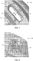
- FIGs 7 and 8 show the preferred flap 24 folded into an open position, as it would be if a beverage were flowing through the drink-through opening 29.
- flap 24 opens, the flap corners 28 curl against the orifice side wall 25 as shown.
- the living hinge 26 is preferably located along one of the two linear edges at the base of the orifice side wall 25.
- the flap 24 opens from inward to outward, as best seen in Figures 7 & 8 .
- a violently agitated beverage ejecting through the drink-through orifice 18 is redirected by the inwardly angled non-relaxed flap 24 into the spill cavity 14.
- the flap 24 in the base of the chamber 23 is capable of opening when subjected to a negative air pressure generated by a user through the drink-through orifice 18 to allow liquid to pass through the chamber 23 and the drink-through orifice 18. Otherwise, the flap 24 remains in a closed position to restrict the flow of liquid through the chamber 23 and the drink-through orifice 18.
- stamping of drink-through openings is a common secondary process subsequent to vacuum-formation of the thermoplastic material.
- the stamping process typically consists of an array of hardened metallic cutting tools impacting upon a mating metallic receiving surface with the thermoplastic material being supported by the receiving surface during the cutting process.
- all cuts are performed simultaneously even though they are often on different horizontal planes.
- the cuts typically include the cutting or punching of the drink hole, the punching of vent and drain holes, and the cutting out of the lid itself from the thermoplastic material.
- the present disclosure introduces a method for die cutting the flap 24 within the base of chamber 23 that is preferably both primarily horizontal and planar, as most clearly viewed in Figures 6 and 9 .
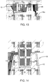
- Figure 13 not only illustrates a method for die cutting the flap 24, but also illustrates how the vent hole 22, the flap 24, and the lid 10 can all be cut simultaneously with a singular cutting stroke.
- a support plate 41 is typically shaped similar to the vacuum-formed lid 10. In production, the support plate 41 often serves as the mold used to form the thermoplastic material and a receiving surface to cut the thermoplastic material, thereby combining the vacuum forming process with the cutting operation. This manufacturing technique saves time and cost by eliminating the need for transferring the molded sheets from one station to the next.
- a die mounting plate 42 aligns with the support plate 41 and holds all the cutting tools: a vent block die 43 with a needle punch 44 for cutting a small vent hole; a chamber block die 50 with a cutting blade 51 for cutting in the flap 24 or the drink-through opening 29; and a ring die 49 for cutting the lid 10 away from the remainder of the thermoplastic sheet 10a.
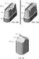
- Figures 14 and 15A-15B illustrate more clearly the die cutting blade 51 of the chamber block die 50 for cutting in the flap 24.
- Figures 15A and 15B show alternative cutting blades 51 for cutting the two preferred configurations for the living hinge 26, shown in Figures 5A and 5B respectively.
- no waste is generated by cutting in the flap 24, thus eliminating the cost associated with keeping the support plate 41 clear of waste build-up.
- Figures 15A-15B and 16 where it can be seen that the block dies 43 and 50 have contoured portions 47 and 52 respectively.
- the contoured portions 47 and 52 conform to the contours of the lid 10.
- the chamber block die 50 inserts into the chamber 23 where the contoured portion 52 essentially mates with the contour of chamber 23.
- vent block die 43 inserts into channel 21 where the contoured portion 47 essentially mates with the contour of the channel 21.
- the contoured portions 47 and 52 enable the cutting portions, the needle punch 44 and the cutting blade 51, to be relatively short thereby increasing their strength and durability.
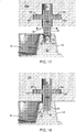
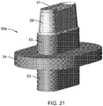
- FIG. 17 and 18 illustrate a floating block die 50a similar to the chamber block die 50 except having a flange member 54 that is horizontal and surrounds a block die body 53, best viewed in Figure 21 .
- the mounting plate 42a includes a die chamber 55 for holding the floating block die 50a.
- the die chamber 55 is further defined by a radial slot 57 that is also horizontal and surrounds the die chamber 55.
- the floating block die 50a is supported within the die chamber 55 by the flange member 54 which inserts into the radial slot 57.
- the floating block die 50a is capable of lateral movement 56 because of space provided between vertical surfaces within the die chamber 55.
- the floating block die 50a is restricted from vertical movement within die chamber 55 because of the restricted clearance between horizontal contacting surfaces within radial slot 57. If the floating block die 50a is aligned with the chamber 23, as shown in Figure 17 , there will be no lateral movement 56 during the cutting process as shown in Figure 18 .
- the contoured portion 52 of the floating block die 50a contacts the orifice side wall 25 prior to die cutting, as shown in Figure 19 .
- the downwardly and inwardly sloping orifice side wall 25 exerts a lateral force to the floating block die 50a thereby causing the floating block die 50a to move laterally into the proper alignment for cutting, as shown in Figure 20 .
- FIG. 22 Another method for self-aligning cutting dies with the thermo-formed disposable dome cup lid 10, introduces a separate floating mounting plate 42a for each cup lid 10, as shown in Figures 22 and 23 .
- a mounting plate base 58 holds an array of similar floating mounting plates 42a that align with the support plate 41.
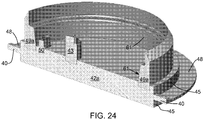
- the floating mounting plate 42a includes a mounting plate flange 48 that is horizontal and surrounds the mounting plate side wall 45, best viewed in Figure 24 .
- a contoured ring die 49a is mounted to the floating mounting plate 42a for separating the lid 10 from the remainder of the thermoplastic material 10a.
- the floating mounting plate 42a also contains all cutting tools for cutting each cup lid 10 including the chamber block die 50 and the vent block die 43.
- the floating mounting plate 42a is mounted within a mounting plate chamber 59 in the mounting plate base 58.
- the mounting plate chamber 59 is further defined by a radial chamber slot 60.
- the floating mounting plate 42a is supported within the mounting plate chamber 59 by the mounting plate flange 48 which inserts into the radial chamber slot 60.
- the floating mounting plate 42a is capable of lateral movement 56 because of space provided between vertical surfaces within the mounting plate chamber 59.
- the floating mounting plate 42a is restricted from vertical movement within mounting plate chamber 59 because of the restricted clearance between horizontal contacting surfaces within the radial chamber slot 60.
- the floating mounting plate 42a is restricted from rotational movement within the mounting plate base 58 by one or more flange tabs 40 shown in Figure 24 . Rotational alignment is required if the floating mounting plate 42a includes cutting tools within the interior of the contoured ring die 49a. If the floating mounting plate 42a is aligned with the lid 10, as shown in Figure 22 , there will be no lateral movement 56 during the cutting process as shown in Figure 22 . However, if a minor misalignment exists between the floating mounting plate 42a and the cup lid 10, the annular contoured portion 61 of the annular ring die 49a contacts the annular outer side wall 12 of the formed cup lid 10 prior to die cutting.
Landscapes
- Engineering & Computer Science (AREA)
- Mechanical Engineering (AREA)
- Closures For Containers (AREA)
- Table Devices Or Equipment (AREA)
Priority Applications (1)
| Application Number | Priority Date | Filing Date | Title |
|---|---|---|---|
| HRP20170870TT HRP20170870T1 (hr) | 2012-07-17 | 2013-07-15 | Poklopac jednokratne putne šalice otporan na prolijevanje |
Applications Claiming Priority (3)
| Application Number | Priority Date | Filing Date | Title |
|---|---|---|---|
| US201261672514P | 2012-07-17 | 2012-07-17 | |
| US201361774471P | 2013-03-07 | 2013-03-07 | |
| PCT/US2013/050562 WO2014014844A1 (en) | 2012-07-17 | 2013-07-15 | Spill resistant disposable travel cup lid |
Publications (3)
| Publication Number | Publication Date |
|---|---|
| EP2874896A1 EP2874896A1 (en) | 2015-05-27 |
| EP2874896A4 EP2874896A4 (en) | 2015-12-16 |
| EP2874896B1 true EP2874896B1 (en) | 2017-03-22 |
Family
ID=49949196
Family Applications (1)
| Application Number | Title | Priority Date | Filing Date |
|---|---|---|---|
| EP13819706.6A Active EP2874896B1 (en) | 2012-07-17 | 2013-07-15 | Spill resistant disposable travel cup lid |
Country Status (11)
| Country | Link |
|---|---|
| EP (1) | EP2874896B1 (da) |
| CN (1) | CN104411595B (da) |
| CA (1) | CA2876022C (da) |
| DK (1) | DK2874896T3 (da) |
| ES (1) | ES2628986T3 (da) |
| HR (1) | HRP20170870T1 (da) |
| HU (1) | HUE033631T2 (da) |
| LT (1) | LT2874896T (da) |
| PL (1) | PL2874896T3 (da) |
| PT (1) | PT2874896T (da) |
| WO (1) | WO2014014844A1 (da) |
Families Citing this family (12)
| Publication number | Priority date | Publication date | Assignee | Title |
|---|---|---|---|---|
| US10494151B2 (en) | 2014-04-01 | 2019-12-03 | Gpcp Ip Holdings Llc | Reclosable cup lid |
| WO2015170302A2 (en) * | 2014-05-08 | 2015-11-12 | Santos Iii Alfred M | Improvements for containers and covers |
| CN104960770A (zh) * | 2015-07-02 | 2015-10-07 | 济南大学 | 单向口防倒漏饮料盒 |
| US10285521B2 (en) | 2015-09-02 | 2019-05-14 | Gpcp Ip Holdings Llc | Disposable cup lid |
| GB201516783D0 (en) * | 2015-09-22 | 2015-11-04 | Sloan Craig | Lid for a beverage container |
| SE540423C2 (en) * | 2017-02-08 | 2018-09-11 | Unicup Scandinavia Ab | A disposable lid for beverage containers |
| WO2019018650A1 (en) * | 2017-07-21 | 2019-01-24 | Vaporpath, Inc. | DRINK TANK COVER FOR DRINKING DIRECTLY THROUGH THE SAME, WHICH CAN BE REFERRED, WHICH IS RESISTANT TO OVERFLOWS AND HAS A FREEZING STRUCTURE |
| CN209777222U (zh) * | 2018-12-26 | 2019-12-13 | 刘文钦 | 一种具可盖合易撕纸杯盖 |
| USD945264S1 (en) | 2019-08-15 | 2022-03-08 | Berry Global, Inc. | Drink cup lid |
| TWI725825B (zh) * | 2020-04-23 | 2021-04-21 | 欣全實業股份有限公司 | 塑膠杯蓋的模具總成 |
| WO2022086876A1 (en) | 2020-10-19 | 2022-04-28 | Vioralid, Llc | Reclosable disposable lid |
| CN114873068B (zh) * | 2022-04-25 | 2024-01-23 | 格来纳塑料科技(苏州)有限公司 | 饮口大小可调式饮料盖 |
Family Cites Families (9)
| Publication number | Priority date | Publication date | Assignee | Title |
|---|---|---|---|---|
| US7591393B2 (en) * | 2004-02-06 | 2009-09-22 | Crudgington Jr Cleveland Benededict | Disposable drinking cup lid |
| US20060071008A1 (en) * | 2004-09-17 | 2006-04-06 | Insulair, Inc. | Lid with bistably valved drinking spout |
| DE202005018994U1 (de) * | 2005-12-05 | 2007-04-12 | Obrist Gmbh | Vorrichtung mit einer Öffnung |
| US8113379B2 (en) * | 2006-08-31 | 2012-02-14 | Dopaco, Inc. | Hot cup lid |
| US7845514B2 (en) * | 2007-03-06 | 2010-12-07 | Dixie Consumer Products Llc | Filled polystyrene tear back container lids |
| US20090308882A1 (en) * | 2008-06-13 | 2009-12-17 | Hundley Bobby V | Straw-Receptive Drink-Through Cup Lid |
| US8727163B2 (en) * | 2009-04-16 | 2014-05-20 | Joel Chrisman | Splash resistant lids, container assemblies including such lids and related methods |
| US20110049171A1 (en) * | 2009-08-26 | 2011-03-03 | Morgan Daniel R | Cup Lid |
| CN201612437U (zh) * | 2010-03-22 | 2010-10-27 | 苏州展一贸易有限公司 | 一种热饮杯杯盖 |
-
2013
- 2013-07-15 CA CA2876022A patent/CA2876022C/en active Active
- 2013-07-15 PL PL13819706T patent/PL2874896T3/pl unknown
- 2013-07-15 PT PT138197066T patent/PT2874896T/pt unknown
- 2013-07-15 EP EP13819706.6A patent/EP2874896B1/en active Active
- 2013-07-15 DK DK13819706.6T patent/DK2874896T3/da active
- 2013-07-15 HU HUE13819706A patent/HUE033631T2/en unknown
- 2013-07-15 LT LTEP13819706.6T patent/LT2874896T/lt unknown
- 2013-07-15 ES ES13819706.6T patent/ES2628986T3/es active Active
- 2013-07-15 HR HRP20170870TT patent/HRP20170870T1/hr unknown
- 2013-07-15 WO PCT/US2013/050562 patent/WO2014014844A1/en not_active Ceased
- 2013-07-15 CN CN201380035352.4A patent/CN104411595B/zh not_active Expired - Fee Related
Non-Patent Citations (1)
| Title |
|---|
| None * |
Also Published As
| Publication number | Publication date |
|---|---|
| WO2014014844A1 (en) | 2014-01-23 |
| HUE033631T2 (en) | 2017-12-28 |
| CN104411595A (zh) | 2015-03-11 |
| EP2874896A4 (en) | 2015-12-16 |
| CA2876022A1 (en) | 2014-01-23 |
| DK2874896T3 (da) | 2017-07-17 |
| PL2874896T3 (pl) | 2017-08-31 |
| CN104411595B (zh) | 2017-08-22 |
| CA2876022C (en) | 2020-12-29 |
| PT2874896T (pt) | 2017-06-01 |
| HRP20170870T1 (hr) | 2017-08-25 |
| ES2628986T3 (es) | 2017-08-04 |
| EP2874896A1 (en) | 2015-05-27 |
| LT2874896T (lt) | 2017-06-26 |
Similar Documents
| Publication | Publication Date | Title |
|---|---|---|
| EP2874896B1 (en) | Spill resistant disposable travel cup lid | |
| US9833960B2 (en) | Spill resistant disposable travel cup lid | |
| US7591393B2 (en) | Disposable drinking cup lid | |
| JP5320385B2 (ja) | 再閉鎖可能なカップ蓋 | |
| US6505753B1 (en) | Cup lid having combined straw slot depression and tear back lid retainer | |
| US4767019A (en) | Splash resistant cup lid | |
| US20260054888A1 (en) | Drink cup lid | |
| US9814334B2 (en) | Drink cup lid | |
| US6948633B2 (en) | Cup lid having combined straw slot depression and tear back lid retainer | |
| CN100400388C (zh) | 具有密封塞的可再封闭盖 | |
| US7185784B2 (en) | Drinking containers | |
| US20140284344A1 (en) | Drink cup lid | |
| US20070095832A1 (en) | Disposable cup lid | |
| US20130037558A1 (en) | One-piece lock-back lid | |
| US7789260B2 (en) | Disposable cup lid | |
| WO2014040039A1 (en) | Sippy cup soft spout with method of forming the same | |
| US10940979B1 (en) | Disposable beverage lid | |
| US12312129B2 (en) | Thermoformed closure with overlapping tab | |
| WO2015109006A1 (en) | Spill resistant disposable travel cup lid | |
| CN217075475U (zh) | 盖子以及杯子 | |
| US7906067B1 (en) | Method for making a spill-proof lid | |
| WO2006124501A2 (en) | Disposable cup lid | |
| HK1110565A (en) | Reclosable cup lid |
Legal Events
| Date | Code | Title | Description |
|---|---|---|---|
| PUAI | Public reference made under article 153(3) epc to a published international application that has entered the european phase |
Free format text: ORIGINAL CODE: 0009012 |
|
| 17P | Request for examination filed |
Effective date: 20150123 |
|
| AK | Designated contracting states |
Kind code of ref document: A1 Designated state(s): AL AT BE BG CH CY CZ DE DK EE ES FI FR GB GR HR HU IE IS IT LI LT LU LV MC MK MT NL NO PL PT RO RS SE SI SK SM TR |
|
| AX | Request for extension of the european patent |
Extension state: BA ME |
|
| DAX | Request for extension of the european patent (deleted) | ||
| RA4 | Supplementary search report drawn up and despatched (corrected) |
Effective date: 20151116 |
|
| RIC1 | Information provided on ipc code assigned before grant |
Ipc: B65D 43/02 20060101AFI20151110BHEP Ipc: A47G 19/22 20060101ALI20151110BHEP Ipc: B29C 51/10 20060101ALI20151110BHEP |
|
| RIC1 | Information provided on ipc code assigned before grant |
Ipc: B65D 43/02 20060101AFI20160914BHEP Ipc: A47G 19/22 20060101ALI20160914BHEP Ipc: B29C 51/10 20060101ALI20160914BHEP |
|
| GRAP | Despatch of communication of intention to grant a patent |
Free format text: ORIGINAL CODE: EPIDOSNIGR1 |
|
| STAA | Information on the status of an ep patent application or granted ep patent |
Free format text: STATUS: GRANT OF PATENT IS INTENDED |
|
| INTG | Intention to grant announced |
Effective date: 20161114 |
|
| GRAS | Grant fee paid |
Free format text: ORIGINAL CODE: EPIDOSNIGR3 |
|
| GRAA | (expected) grant |
Free format text: ORIGINAL CODE: 0009210 |
|
| STAA | Information on the status of an ep patent application or granted ep patent |
Free format text: STATUS: THE PATENT HAS BEEN GRANTED |
|
| AK | Designated contracting states |
Kind code of ref document: B1 Designated state(s): AL AT BE BG CH CY CZ DE DK EE ES FI FR GB GR HR HU IE IS IT LI LT LU LV MC MK MT NL NO PL PT RO RS SE SI SK SM TR |
|
| REG | Reference to a national code |
Ref country code: GB Ref legal event code: FG4D |
|
| REG | Reference to a national code |
Ref country code: CH Ref legal event code: EP |
|
| REG | Reference to a national code |
Ref country code: AT Ref legal event code: REF Ref document number: 877483 Country of ref document: AT Kind code of ref document: T Effective date: 20170415 |
|
| REG | Reference to a national code |
Ref country code: IE Ref legal event code: FG4D |
|
| REG | Reference to a national code |
Ref country code: DE Ref legal event code: R096 Ref document number: 602013018994 Country of ref document: DE |
|
| REG | Reference to a national code |
Ref country code: PT Ref legal event code: SC4A Ref document number: 2874896 Country of ref document: PT Date of ref document: 20170601 Kind code of ref document: T Free format text: AVAILABILITY OF NATIONAL TRANSLATION Effective date: 20170523 |
|
| REG | Reference to a national code |
Ref country code: HR Ref legal event code: TUEP Ref document number: P20170870 Country of ref document: HR |
|
| REG | Reference to a national code |
Ref country code: RO Ref legal event code: EPE |
|
| REG | Reference to a national code |
Ref country code: NL Ref legal event code: FP |
|
| REG | Reference to a national code |
Ref country code: FR Ref legal event code: PLFP Year of fee payment: 5 |
|
| REG | Reference to a national code |
Ref country code: DK Ref legal event code: T3 Effective date: 20170706 |
|
| REG | Reference to a national code |
Ref country code: SE Ref legal event code: TRGR |
|
| REG | Reference to a national code |
Ref country code: HR Ref legal event code: ODRP Ref document number: P20170870 Country of ref document: HR Payment date: 20170728 Year of fee payment: 5 |
|
| REG | Reference to a national code |
Ref country code: ES Ref legal event code: FG2A Ref document number: 2628986 Country of ref document: ES Kind code of ref document: T3 Effective date: 20170804 |
|
| REG | Reference to a national code |
Ref country code: HR Ref legal event code: T1PR Ref document number: P20170870 Country of ref document: HR |
|
| PG25 | Lapsed in a contracting state [announced via postgrant information from national office to epo] |
Ref country code: RS Free format text: LAPSE BECAUSE OF FAILURE TO SUBMIT A TRANSLATION OF THE DESCRIPTION OR TO PAY THE FEE WITHIN THE PRESCRIBED TIME-LIMIT Effective date: 20170322 Ref country code: LV Free format text: LAPSE BECAUSE OF FAILURE TO SUBMIT A TRANSLATION OF THE DESCRIPTION OR TO PAY THE FEE WITHIN THE PRESCRIBED TIME-LIMIT Effective date: 20170322 Ref country code: BG Free format text: LAPSE BECAUSE OF FAILURE TO SUBMIT A TRANSLATION OF THE DESCRIPTION OR TO PAY THE FEE WITHIN THE PRESCRIBED TIME-LIMIT Effective date: 20170622 |
|
| REG | Reference to a national code |
Ref country code: NO Ref legal event code: T2 Effective date: 20170322 |
|
| PG25 | Lapsed in a contracting state [announced via postgrant information from national office to epo] |
Ref country code: EE Free format text: LAPSE BECAUSE OF FAILURE TO SUBMIT A TRANSLATION OF THE DESCRIPTION OR TO PAY THE FEE WITHIN THE PRESCRIBED TIME-LIMIT Effective date: 20170322 Ref country code: SK Free format text: LAPSE BECAUSE OF FAILURE TO SUBMIT A TRANSLATION OF THE DESCRIPTION OR TO PAY THE FEE WITHIN THE PRESCRIBED TIME-LIMIT Effective date: 20170322 |
|
| PGFP | Annual fee paid to national office [announced via postgrant information from national office to epo] |
Ref country code: HR Payment date: 20170728 Year of fee payment: 5 |
|
| REG | Reference to a national code |
Ref country code: GR Ref legal event code: EP Ref document number: 20170401657 Country of ref document: GR Effective date: 20171023 |
|
| PG25 | Lapsed in a contracting state [announced via postgrant information from national office to epo] |
Ref country code: IS Free format text: LAPSE BECAUSE OF FAILURE TO SUBMIT A TRANSLATION OF THE DESCRIPTION OR TO PAY THE FEE WITHIN THE PRESCRIBED TIME-LIMIT Effective date: 20170722 Ref country code: SM Free format text: LAPSE BECAUSE OF FAILURE TO SUBMIT A TRANSLATION OF THE DESCRIPTION OR TO PAY THE FEE WITHIN THE PRESCRIBED TIME-LIMIT Effective date: 20170322 |
|
| REG | Reference to a national code |
Ref country code: HU Ref legal event code: AG4A Ref document number: E033631 Country of ref document: HU |
|
| REG | Reference to a national code |
Ref country code: DE Ref legal event code: R097 Ref document number: 602013018994 Country of ref document: DE |
|
| PLBE | No opposition filed within time limit |
Free format text: ORIGINAL CODE: 0009261 |
|
| STAA | Information on the status of an ep patent application or granted ep patent |
Free format text: STATUS: NO OPPOSITION FILED WITHIN TIME LIMIT |
|
| REG | Reference to a national code |
Ref country code: DE Ref legal event code: R119 Ref document number: 602013018994 Country of ref document: DE |
|
| 26N | No opposition filed |
Effective date: 20180102 |
|
| PG25 | Lapsed in a contracting state [announced via postgrant information from national office to epo] |
Ref country code: SI Free format text: LAPSE BECAUSE OF FAILURE TO SUBMIT A TRANSLATION OF THE DESCRIPTION OR TO PAY THE FEE WITHIN THE PRESCRIBED TIME-LIMIT Effective date: 20170322 |
|
| REG | Reference to a national code |
Ref country code: NL Ref legal event code: MM Effective date: 20170801 |
|
| REG | Reference to a national code |
Ref country code: HU Ref legal event code: HC9C |
|
| PG25 | Lapsed in a contracting state [announced via postgrant information from national office to epo] |
Ref country code: DE Free format text: LAPSE BECAUSE OF NON-PAYMENT OF DUE FEES Effective date: 20180201 Ref country code: RO Free format text: LAPSE BECAUSE OF NON-PAYMENT OF DUE FEES Effective date: 20170322 Ref country code: NL Free format text: LAPSE BECAUSE OF NON-PAYMENT OF DUE FEES Effective date: 20170801 |
|
| REG | Reference to a national code |
Ref country code: FR Ref legal event code: PLFP Year of fee payment: 6 |
|
| PG25 | Lapsed in a contracting state [announced via postgrant information from national office to epo] |
Ref country code: LU Free format text: LAPSE BECAUSE OF NON-PAYMENT OF DUE FEES Effective date: 20170715 |
|
| REG | Reference to a national code |
Ref country code: NL Ref legal event code: NE Effective date: 20180829 |
|
| PG25 | Lapsed in a contracting state [announced via postgrant information from national office to epo] |
Ref country code: MT Free format text: LAPSE BECAUSE OF NON-PAYMENT OF DUE FEES Effective date: 20170715 |
|
| REG | Reference to a national code |
Ref country code: HR Ref legal event code: PBON Ref document number: P20170870 Country of ref document: HR Effective date: 20180715 |
|
| PG25 | Lapsed in a contracting state [announced via postgrant information from national office to epo] |
Ref country code: HR Free format text: LAPSE BECAUSE OF NON-PAYMENT OF DUE FEES Effective date: 20180715 |
|
| REG | Reference to a national code |
Ref country code: NL Ref legal event code: CF Effective date: 20190531 |
|
| PG25 | Lapsed in a contracting state [announced via postgrant information from national office to epo] |
Ref country code: MC Free format text: LAPSE BECAUSE OF FAILURE TO SUBMIT A TRANSLATION OF THE DESCRIPTION OR TO PAY THE FEE WITHIN THE PRESCRIBED TIME-LIMIT Effective date: 20170322 |
|
| PG25 | Lapsed in a contracting state [announced via postgrant information from national office to epo] |
Ref country code: CY Free format text: LAPSE BECAUSE OF FAILURE TO SUBMIT A TRANSLATION OF THE DESCRIPTION OR TO PAY THE FEE WITHIN THE PRESCRIBED TIME-LIMIT Effective date: 20170322 |
|
| PG25 | Lapsed in a contracting state [announced via postgrant information from national office to epo] |
Ref country code: MK Free format text: LAPSE BECAUSE OF FAILURE TO SUBMIT A TRANSLATION OF THE DESCRIPTION OR TO PAY THE FEE WITHIN THE PRESCRIBED TIME-LIMIT Effective date: 20170322 |
|
| PG25 | Lapsed in a contracting state [announced via postgrant information from national office to epo] |
Ref country code: NL Free format text: LAPSE BECAUSE OF NON-PAYMENT OF DUE FEES Effective date: 20170801 |
|
| PGRI | Patent reinstated in contracting state [announced from national office to epo] |
Ref country code: NL Effective date: 20191122 |
|
| PG25 | Lapsed in a contracting state [announced via postgrant information from national office to epo] |
Ref country code: TR Free format text: LAPSE BECAUSE OF FAILURE TO SUBMIT A TRANSLATION OF THE DESCRIPTION OR TO PAY THE FEE WITHIN THE PRESCRIBED TIME-LIMIT Effective date: 20170322 |
|
| PG25 | Lapsed in a contracting state [announced via postgrant information from national office to epo] |
Ref country code: HU Free format text: LAPSE BECAUSE OF NON-PAYMENT OF DUE FEES Effective date: 20190716 |
|
| PGRI | Patent reinstated in contracting state [announced from national office to epo] |
Ref country code: HU Effective date: 20200305 |
|
| REG | Reference to a national code |
Ref country code: DE Ref legal event code: R073 Ref document number: 602013018994 Country of ref document: DE |
|
| REG | Reference to a national code |
Ref country code: DE Ref legal event code: R082 Ref document number: 602013018994 Country of ref document: DE Representative=s name: EISENFUEHR SPEISER PATENTANWAELTE RECHTSANWAEL, DE |
|
| PG25 | Lapsed in a contracting state [announced via postgrant information from national office to epo] |
Ref country code: AL Free format text: LAPSE BECAUSE OF FAILURE TO SUBMIT A TRANSLATION OF THE DESCRIPTION OR TO PAY THE FEE WITHIN THE PRESCRIBED TIME-LIMIT Effective date: 20170322 |
|
| PG25 | Lapsed in a contracting state [announced via postgrant information from national office to epo] |
Ref country code: HU Free format text: LAPSE BECAUSE OF NON-PAYMENT OF DUE FEES Effective date: 20190716 |
|
| PGRI | Patent reinstated in contracting state [announced from national office to epo] |
Ref country code: HU Effective date: 20200305 |
|
| REG | Reference to a national code |
Ref country code: DE Ref legal event code: R124 Ref document number: 602013018994 Country of ref document: DE |
|
| PGFP | Annual fee paid to national office [announced via postgrant information from national office to epo] |
Ref country code: IT Payment date: 20220622 Year of fee payment: 11 |
|
| PGFP | Annual fee paid to national office [announced via postgrant information from national office to epo] |
Ref country code: RO Payment date: 20230523 Year of fee payment: 11 Ref country code: NO Payment date: 20230523 Year of fee payment: 11 Ref country code: NL Payment date: 20230518 Year of fee payment: 11 Ref country code: LT Payment date: 20230525 Year of fee payment: 11 Ref country code: IE Payment date: 20230518 Year of fee payment: 11 Ref country code: FR Payment date: 20230517 Year of fee payment: 11 Ref country code: DK Payment date: 20230508 Year of fee payment: 11 Ref country code: CZ Payment date: 20230509 Year of fee payment: 11 |
|
| PGFP | Annual fee paid to national office [announced via postgrant information from national office to epo] |
Ref country code: SE Payment date: 20230522 Year of fee payment: 11 Ref country code: GR Payment date: 20230517 Year of fee payment: 11 Ref country code: FI Payment date: 20230517 Year of fee payment: 11 |
|
| PGFP | Annual fee paid to national office [announced via postgrant information from national office to epo] |
Ref country code: BE Payment date: 20230508 Year of fee payment: 11 |
|
| PGFP | Annual fee paid to national office [announced via postgrant information from national office to epo] |
Ref country code: GB Payment date: 20230523 Year of fee payment: 11 Ref country code: ES Payment date: 20230801 Year of fee payment: 11 Ref country code: CH Payment date: 20230801 Year of fee payment: 11 Ref country code: AT Payment date: 20230509 Year of fee payment: 11 |
|
| PGFP | Annual fee paid to national office [announced via postgrant information from national office to epo] |
Ref country code: PT Payment date: 20230612 Year of fee payment: 11 Ref country code: HU Payment date: 20230517 Year of fee payment: 11 |
|
| REG | Reference to a national code |
Ref country code: LT Ref legal event code: MM4D Effective date: 20240715 |
|
| REG | Reference to a national code |
Ref country code: DK Ref legal event code: EBP Effective date: 20240731 |
|
| REG | Reference to a national code |
Ref country code: CH Ref legal event code: PL |
|
| REG | Reference to a national code |
Ref country code: SE Ref legal event code: EUG |
|
| REG | Reference to a national code |
Ref country code: NL Ref legal event code: MM Effective date: 20240801 |
|
| REG | Reference to a national code |
Ref country code: AT Ref legal event code: MM01 Ref document number: 877483 Country of ref document: AT Kind code of ref document: T Effective date: 20240715 |
|
| GBPC | Gb: european patent ceased through non-payment of renewal fee |
Effective date: 20240715 |
|
| PG25 | Lapsed in a contracting state [announced via postgrant information from national office to epo] |
Ref country code: PT Free format text: LAPSE BECAUSE OF NON-PAYMENT OF DUE FEES Effective date: 20250115 |
|
| PG25 | Lapsed in a contracting state [announced via postgrant information from national office to epo] |
Ref country code: FI Free format text: LAPSE BECAUSE OF NON-PAYMENT OF DUE FEES Effective date: 20240715 Ref country code: RO Free format text: LAPSE BECAUSE OF NON-PAYMENT OF DUE FEES Effective date: 20240715 Ref country code: LT Free format text: LAPSE BECAUSE OF NON-PAYMENT OF DUE FEES Effective date: 20240715 Ref country code: NL Free format text: LAPSE BECAUSE OF NON-PAYMENT OF DUE FEES Effective date: 20240801 |
|
| PG25 | Lapsed in a contracting state [announced via postgrant information from national office to epo] |
Ref country code: NO Free format text: LAPSE BECAUSE OF NON-PAYMENT OF DUE FEES Effective date: 20240731 |
|
| PG25 | Lapsed in a contracting state [announced via postgrant information from national office to epo] |
Ref country code: AT Free format text: LAPSE BECAUSE OF NON-PAYMENT OF DUE FEES Effective date: 20240715 Ref country code: CH Free format text: LAPSE BECAUSE OF NON-PAYMENT OF DUE FEES Effective date: 20240731 Ref country code: GR Free format text: LAPSE BECAUSE OF NON-PAYMENT OF DUE FEES Effective date: 20250205 Ref country code: BE Free format text: LAPSE BECAUSE OF NON-PAYMENT OF DUE FEES Effective date: 20240731 |
|
| PG25 | Lapsed in a contracting state [announced via postgrant information from national office to epo] |
Ref country code: FR Free format text: LAPSE BECAUSE OF NON-PAYMENT OF DUE FEES Effective date: 20240731 Ref country code: CZ Free format text: LAPSE BECAUSE OF NON-PAYMENT OF DUE FEES Effective date: 20240715 Ref country code: PL Free format text: LAPSE BECAUSE OF NON-PAYMENT OF DUE FEES Effective date: 20170715 |
|
| PG25 | Lapsed in a contracting state [announced via postgrant information from national office to epo] |
Ref country code: GB Free format text: LAPSE BECAUSE OF NON-PAYMENT OF DUE FEES Effective date: 20240715 |
|
| REG | Reference to a national code |
Ref country code: BE Ref legal event code: MM Effective date: 20240731 |
|
| PG25 | Lapsed in a contracting state [announced via postgrant information from national office to epo] |
Ref country code: DK Free format text: LAPSE BECAUSE OF NON-PAYMENT OF DUE FEES Effective date: 20240731 |
|
| PG25 | Lapsed in a contracting state [announced via postgrant information from national office to epo] |
Ref country code: IT Free format text: LAPSE BECAUSE OF NON-PAYMENT OF DUE FEES Effective date: 20240715 |
|
| PG25 | Lapsed in a contracting state [announced via postgrant information from national office to epo] |
Ref country code: IE Free format text: LAPSE BECAUSE OF NON-PAYMENT OF DUE FEES Effective date: 20240715 |
|
| REG | Reference to a national code |
Ref country code: ES Ref legal event code: FD2A Effective date: 20250829 |
|
| PG25 | Lapsed in a contracting state [announced via postgrant information from national office to epo] |
Ref country code: ES Free format text: LAPSE BECAUSE OF NON-PAYMENT OF DUE FEES Effective date: 20240716 |
|
| PG25 | Lapsed in a contracting state [announced via postgrant information from national office to epo] |
Ref country code: SE Free format text: LAPSE BECAUSE OF NON-PAYMENT OF DUE FEES Effective date: 20240716 |