EP2874924B1 - Blinklichtsteuerung für portaldatenleser - Google Patents
Blinklichtsteuerung für portaldatenleser Download PDFInfo
- Publication number
- EP2874924B1 EP2874924B1 EP13819750.4A EP13819750A EP2874924B1 EP 2874924 B1 EP2874924 B1 EP 2874924B1 EP 13819750 A EP13819750 A EP 13819750A EP 2874924 B1 EP2874924 B1 EP 2874924B1
- Authority
- EP
- European Patent Office
- Prior art keywords
- item
- indicator
- data reader
- light
- alighting
- Prior art date
- Legal status (The legal status is an assumption and is not a legal conclusion. Google has not performed a legal analysis and makes no representation as to the accuracy of the status listed.)
- Active
Links
Images




Classifications
-
- G—PHYSICS
- G06—COMPUTING OR CALCULATING; COUNTING
- G06K—GRAPHICAL DATA READING; PRESENTATION OF DATA; RECORD CARRIERS; HANDLING RECORD CARRIERS
- G06K7/00—Methods or arrangements for sensing record carriers, e.g. for reading patterns
- G06K7/01—Details
-
- G—PHYSICS
- G06—COMPUTING OR CALCULATING; COUNTING
- G06K—GRAPHICAL DATA READING; PRESENTATION OF DATA; RECORD CARRIERS; HANDLING RECORD CARRIERS
- G06K7/00—Methods or arrangements for sensing record carriers, e.g. for reading patterns
- G06K7/10—Methods or arrangements for sensing record carriers, e.g. for reading patterns by electromagnetic radiation, e.g. optical sensing; by corpuscular radiation
- G06K7/10544—Methods or arrangements for sensing record carriers, e.g. for reading patterns by electromagnetic radiation, e.g. optical sensing; by corpuscular radiation by scanning of the records by radiation in the optical part of the electromagnetic spectrum
- G06K7/10821—Methods or arrangements for sensing record carriers, e.g. for reading patterns by electromagnetic radiation, e.g. optical sensing; by corpuscular radiation by scanning of the records by radiation in the optical part of the electromagnetic spectrum further details of bar or optical code scanning devices
-
- A—HUMAN NECESSITIES
- A47—FURNITURE; DOMESTIC ARTICLES OR APPLIANCES; COFFEE MILLS; SPICE MILLS; SUCTION CLEANERS IN GENERAL
- A47F—SPECIAL FURNITURE, FITTINGS, OR ACCESSORIES FOR SHOPS, STOREHOUSES, BARS, RESTAURANTS OR THE LIKE; PAYING COUNTERS
- A47F9/00—Shop, bar, bank or like counters
- A47F9/02—Paying counters
- A47F9/04—Check-out counters, e.g. for self-service stores
- A47F9/046—Arrangement of recording means in or on check-out counters
- A47F9/047—Arrangement of recording means in or on check-out counters for recording self-service articles without cashier or assistant
- A47F9/048—Arrangement of recording means in or on check-out counters for recording self-service articles without cashier or assistant automatically
-
- G—PHYSICS
- G06—COMPUTING OR CALCULATING; COUNTING
- G06Q—INFORMATION AND COMMUNICATION TECHNOLOGY [ICT] SPECIALLY ADAPTED FOR ADMINISTRATIVE, COMMERCIAL, FINANCIAL, MANAGERIAL OR SUPERVISORY PURPOSES; SYSTEMS OR METHODS SPECIALLY ADAPTED FOR ADMINISTRATIVE, COMMERCIAL, FINANCIAL, MANAGERIAL OR SUPERVISORY PURPOSES, NOT OTHERWISE PROVIDED FOR
- G06Q10/00—Administration; Management
- G06Q10/08—Logistics, e.g. warehousing, loading or distribution; Inventory or stock management
-
- G—PHYSICS
- G06—COMPUTING OR CALCULATING; COUNTING
- G06Q—INFORMATION AND COMMUNICATION TECHNOLOGY [ICT] SPECIALLY ADAPTED FOR ADMINISTRATIVE, COMMERCIAL, FINANCIAL, MANAGERIAL OR SUPERVISORY PURPOSES; SYSTEMS OR METHODS SPECIALLY ADAPTED FOR ADMINISTRATIVE, COMMERCIAL, FINANCIAL, MANAGERIAL OR SUPERVISORY PURPOSES, NOT OTHERWISE PROVIDED FOR
- G06Q10/00—Administration; Management
- G06Q10/08—Logistics, e.g. warehousing, loading or distribution; Inventory or stock management
- G06Q10/087—Inventory or stock management, e.g. order filling, procurement or balancing against orders
-
- G—PHYSICS
- G07—CHECKING-DEVICES
- G07G—REGISTERING THE RECEIPT OF CASH, VALUABLES, OR TOKENS
- G07G1/00—Cash registers
- G07G1/0036—Checkout procedures
- G07G1/0045—Checkout procedures with a code reader for reading of an identifying code of the article to be registered, e.g. barcode reader or radio-frequency identity [RFID] reader
-
- G—PHYSICS
- G07—CHECKING-DEVICES
- G07G—REGISTERING THE RECEIPT OF CASH, VALUABLES, OR TOKENS
- G07G1/00—Cash registers
- G07G1/0036—Checkout procedures
- G07G1/0045—Checkout procedures with a code reader for reading of an identifying code of the article to be registered, e.g. barcode reader or radio-frequency identity [RFID] reader
- G07G1/0054—Checkout procedures with a code reader for reading of an identifying code of the article to be registered, e.g. barcode reader or radio-frequency identity [RFID] reader with control of supplementary check-parameters, e.g. weight or number of articles
- G07G1/0063—Checkout procedures with a code reader for reading of an identifying code of the article to be registered, e.g. barcode reader or radio-frequency identity [RFID] reader with control of supplementary check-parameters, e.g. weight or number of articles with means for detecting the geometric dimensions of the article of which the code is read, such as its size or height, for the verification of the registration
Definitions
- the field of the present disclosure relates to systems and methods for item checkout and in certain aspects to retail checkstands or other checkout stands (e.g., a parcel distribution station) that incorporate data readers and other electronic devices.
- the field of the present disclosure further relates generally to data reading devices, and more particularly to automated devices by which items are conveyed, typically on a conveyor, through a read zone of the data reader by which the items are identified such as, for example, by reading optical codes or RFID (radio frequency identification) tags on the items.
- optical code readers also known as scanners, such as manual readers, semi-automatic readers and automated readers, are available to acquire and decode the information encoded in optical codes.
- a manual reader e.g., a hand-held type reader or a fixed-position reader
- a human operator positions an object relative to the reader to read the optical code associated with the object.
- a semi-automatic reader either checker-assisted or self-checkout, objects are moved one at a time by the user into or through the read zone of the reader and the reader then reads the optical code on the object.
- an object is automatically positioned (e.g., transported through the read zone via a conveying system) relative to the reader, with the reader automatically reading the optical code on the object as the object is passed through the read zone of the reader.
- a portal scanner is therefore much different because items are moved not manually (as in a semi-automatic reader) but automatically through the system, possibly with multiple items present in the read zone at the same time, with the operator intervening for resolving exception conditions, such as failure to read a bar code on an item.
- the present inventors have recognized that traditional semi-automatic scanner good read / no read indicators may not be suitable for portal scanner systems.
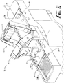
- Figs. 1-2 illustrate a checkstand area 5 including a check station 70 and one automated reader system in the form of a portal or tunnel checkout system 10 according to one example.
- the system 10 includes a portal data reader or scanner unit 12 installed on a checkout counter unit 20 such as may be used, for example, in a high-volume retail establishment such as a grocery store or big-box store.
- the system 10 may also be used in an industrial setting such as a luggage or parcel distribution station, but the operating embodiment will be described primarily in the context of a retail establishment.
- the portal data reader unit 12 includes front and rear arch sections 14, 16 and bottom scanner section 18.
- the checkout counter unit 20 includes an inlet or input end 22, an outlet or exit end 24, and a conveyor system comprising an inlet conveyor section 30 and an outlet conveyor section 32 (collectively conveyor 30/32). Items such as a rectangular package/box 42 and cylindrical can 44 are placed on the inlet or input conveyor section 30 and transported in the direction of direction arrow 26 through the interior of the portal data reader unit 12 (comprising a read zone 13), and then transported out of the interior via outlet or exit conveyor section 32 onto (optional) rollers 39 defining a bagging area 38 where the items are then delivered, boxed, or bagged for removal by the user 3 (e.g., the customer) or other person.
- the user 3 e.g., the customer
- the portal data reader 12 may comprise other types of readers such as a laser scanner, an RFID reader or other suitable type of reader, optical code reader, object recognition system/reader, or a combination of such readers.
- the conveyor system 30/32 may include one or more various types of mechanical conveying systems to move objects through a three-dimensional read zone 13 of the data reader unit 12 so that optical codes disposed on the objects can be read and the objects added to an item transaction list.
- the conveyor system 30/32 may include one or more conveyors, such as conveyor belts.
- the conveyor system 30/32 is operable to move items in the longitudinal direction (shown by arrow 26) at a relatively fast rate (e.g., 200-400 millimeters/second (mm/sec)) so that items can be quickly passed through the read zone 13, read by the data reader 12, and added to the item transaction list.
- a relatively fast rate e.g. 200-400 millimeters/second (mm/sec)
- the conveyor system 30/32 moves items relative to portal data reader 12 that has multiple data capture devices 14, 16 that form arches over a central portion of the conveyors 30/32.
- the data capture devices 14, 16 include various components operative to capture information corresponding to the items that are moved through the arches.
- the data capture devices 14, 16 are illustrated as including an open space therebetween, the data capture devices 14, 16 may be embodied in an elongated tunnel formed over or around the conveyors 30/32.
- the portal data reader 12 may thus be partially open and partially enclosed, such as the example illustrated in Figs. 1-2 , or fully enclosed such as via a tunnel enclosure.
- the portal data reader 12 is illustrated with dual arches 14, 16, alternately a portal data reader may comprise a single arch or more than two arches.
- the configuration of the dual arches of the capture devices 14, 16 creates an open architecture that provides some barrier/inhibition from a customer reaching into the read zone yet provides sight lines for allowing the customer to generally continuously observe items passing through the arches.
- a portal data reader need not include any tunnel or even semi-enclosed arches, but a suitable portal data reader may be constructed with more or less openness.
- the optional bottom reader section of the data reader 12 is operative for reading the bottom side of items as they are passed over a gap 31.
- the gap 31 may be disposed between the front/upstream conveyor section 30 and the rear/downstream conveyor section 32 (i.e., at a center position between the front arch 14 and the rear arch 16). Alternately, the gap 31 may be disposed upstream or downstream of the center position.
- the portal data reader 12 forms a read zone 13 generally defined by the volume beneath and between the arch sections of the data capture devices 14, 16 and above the conveyor 30/32 through which items are passed and may be read by the reading mechanisms with fields of view out from the data capture devices 14, 16 and up through the gap 31.
- the gap 31 may include an optional transparent or slotted transfer plate that may be placed between the conveyor sections 30, 32 to create a smooth transition of items transported from inlet conveyor section 30 to outlet conveyor section 32.
- the inlet conveyor section 30 and outlet conveyor section 32 may comprise a single, continuous conveyor. Further details of systems and methods for bottom reading are disclosed in U.S. Appl. Nos. 61/435,744 filed January 24, 2011 and 13/356,417 filed January 23, 2012 (corresponding to U.S. Published Appl. 2012/0187195 ); and 61/643,820 filed May 7, 2012 .
- Fig. 3 is a block diagram illustrating components of the checkout system 10 of Figs. 1-2 according to one embodiment.
- System 10 includes:
- one type of exception corresponds to an event in which an object passes through the arch sections 14/16, but an optical code is not read by the reader 12.
- Another type of exception corresponds to an event in which an optical code is read, but system 10 does not detect that an object has passed through the system 10.
- Another type of exception corresponds to an event in which one optical code read by the data reader 12 is associated with multiple objects passing through system 10.
- Another type of exception corresponds to an event in which multiple different optical codes read by system 10 are associated with one object passing through system 10.
- Various subsets of the above-described exceptions, as well as other types of exceptions, are possible and applicable to the systems/methods described herein.
- System 10 includes various modules or subsystems to perform various tasks.
- modules or subsystems may include a processor, associated software or hardware constructs, and/or memory to carry out certain functions performed by the systems.
- the processors may be embodied in a single central processing unit, or may be distributed such that a system has its own dedicated processor.
- some examples may be provided as a computer program product including a machine-readable storage medium having stored thereon instructions (in compressed or uncompressed form) that may be used to program a computer (or other electronic device) to perform processes or methods described herein.
- the machine-readable storage medium may include, but is not limited to, hard drives, floppy diskettes, optical disks, CD-ROMs, DVDs, read-only memories (ROMs), random access memories (RAMs), EPROMs, EEPROMs, flash memory, magnetic or optical cards, solid-state memory devices, or other types of media/machine-readable medium suitable for storing electronic instructions. Further, embodiments may also be provided as a computer program product including a machine-readable signal (in compressed or uncompressed form). Examples of machine-readable signals, whether modulated using a carrier or not, include, but are not limited to, signals that a computer system or machine hosting or running a computer program can be configured to access, including signals downloaded through the Internet or other networks. For example, distribution of software may be via CD-ROM or via Internet download.
- the portal data reader 12 in one example configuration is operable to capture images of objects as the objects are transported along conveyor system 30/32.
- the portal data reader 12 identifies whether optical codes disposed on the objects are captured in the images and decodes those optical codes that are captured.
- the portal data reader 12 may include different decoders (e.g., software algorithms, hardware constructs) to decode various types of optical codes including one-dimensional (e.g., linear) codes (e.g., UPC, codabar, code 25, code 39, code 93, code 128, code 11, EAN8, EAN13, plessey, POSTNET) and two-dimensional (e.g., matrix) codes (e.g., aztec code, maxicode, QR code, high-capacity color barcode, data matrix).
- the system 10 may optionally include a separate optical decoding system 110 that receives and decodes the signal from the data reader 12.
- the system 10 may include any of a number of suitable exception detection/determination systems.
- an object measurement system 115 is positioned along conveyor system 30/32 to measure objects that are transported along conveyor system 30/32.
- the object measurement system 115 generates model data that represent three-dimensional models of the objects that are transported along conveyor system 30/32. Further details of this object measurement system 115 are described in U.S. Application Nos. 61/505,935 and 13/357,459 (which published as US 2013/0020391 ).
- the optical code reading system 12 is also operable to generate projection data for optical codes represented in the images it captures.
- the projection data represent back projection rays that project into a three-dimensional view volume of optical code reading system 12. These back projection rays are associated with locations of the representations of the optical codes in the images. Details of example optical code reading system 12 are also described in U.S. Application Nos. 61/435,777 and 13/357,356 (which published as US 2013/0020392 ) incorporated by reference.
- the system 10 may also include an optical code intersection system 125 that is configured to receive the model data from object measurement system 115 and the projection data from optical code reading system 12.
- the optical code intersection system 125 uses the model data and the projection data to determine whether the back projection rays generated for decoded optical codes intersect with the three-dimensional models. Details of the optical code intersection system 125 are also described in U.S. Application Nos. 61/505,935 and 13/357,459 .
- the system 10 may include an optional exception identification system 130 in communication with the optical code intersection system 125.
- the exception identification system 130 identifies whether exceptions occur based on intersection determinations made by the optical code intersection system 125. For example, if an object passes through system 100 and the object measurement system 115 generates a three-dimensional model of the object, but no back projection ray of an optical code intersects with the three-dimensional model, exception identification system 130 identifies this event as an exception.
- the exception identification system 130 is also operable to classify and categorize exceptions by types and subtypes and to generate exception category identification information indicative of the exception types and/or subtypes.
- the system 10 may also include an optical decoding system 110 that receives and decodes the signal from the data reader 12; an object measurement system 115 positioned along conveyor system 30/32 to measure objects that are transported along conveyor system 30/32.
- an object measurement system 115 generates model data that represent three-dimensional models of the objects that are transported along conveyor system 30/32. Further details of the object measurement system 115 are described in U.S. Application Nos. 61/505,935 and 13/357,459 .
- the system 10 may also include an optional exception handling system 135 in communication with exception identification system 130.
- the exception handling system 135 determines in what manner to handle (e.g., resolve) an exception identified by exception identification system 130 based on the exception's type. To this end, the exception category identification information generated by exception identification system 130 is communicated to exception handling system 135.
- Exception handling system 135 is operable to determine that an exception should be resolved in one of multiple ways. For example, exception handling system 135 may determine that an exception is to be automatically resolved by ignoring the exception or manually resolved by an operator.
- the exception handling system 135 may communicate with an optional storage device 140 that stores various types of information associated with exceptions.
- the system 10 may also include an optical decoding system 110 that receives and decodes the signal from the data reader 12 and an object measurement system 115 positioned along conveyor system 30/32 to measure objects that are transported along conveyor system 30/32.
- the object measurement system 115 generates model data that represent three-dimensional models of the objects that are transported along conveyor system 30/32. Further details of the object measurement system 115 are described in U.S. Application Nos. 61/505,935 and 13/357,459 .
- the system 10 may also include an optional object annotation system 145 that is operable to generate annotated image data corresponding to visual representations of exceptions to enable an operator to easily identify which objects that are transported through system 10 have exceptions associated with them.
- the annotated image data generated by object annotation system 145 are communicated to a display screen 50, which displays the visual representations of the exceptions. Further details of the object annotations system 145 are described in U.S. Application Nos. 61/505,935 and 13/357,459 .
- the exception handling system 135 determines how to resolve the exception. Exceptions can be resolved in various ways such as ignore the exception, automatically resolve the exception, and manually resolve the exception (either by the user 3 or by some other person).
- the exception handling system 135 may be user-programmable to handle various exceptions in different ways.
- the customer 3 places items on the inlet conveyor section 30 which transports the items through the data reader 12 and then, on outlet conveyor section 32 to one or more bagging areas 39. If the data capture process is determined to not have been successful for any reason (i.e., that an exception has occurred) then information about this failed attempt to capture the data is communicated to the user 3 or to a checkout clerk so that the exception can be managed.
- One method for communicating this exception information is to provide one or more images (digital photographs) of the item, a video of the item, a 3D image of the item that can be rotated, and data that was captured but that was too ambiguous to determine if the data was correct.
- this data is communicated or displayed to a user 3 via a fixed display screen 50, which may comprise a touch screen.
- the user 3 reviews the information on the fixed screen 50 and interacts with the screen via a keyboard/keypad 52 and/or touch screen 50 or other input device.
- the system 10 may also include a payment receipt system (such as a card reader or cash receiver disposed with the keyboard 52 or touch screen 50 or elsewhere) to enable the customer to insert/swipe a credit card or insert cash for payment.
- a payment receipt system such as a card reader or cash receiver disposed with the keyboard 52 or touch screen 50 or elsewhere
- a number of automated (or semi-automated) checkout systems/stations 10 may be serviced by a checkout clerk, typically seated or standing at a fixed clerk station 70.
- the clerk station 70 includes a video screen 72 (which may be a touch screen or not) on which images and messages pertaining to exceptions (as well as other information) are displayed.
- the clerk station may also include a keyboard 74 and/or touch screen 72 for inputting and interacting with the checkout stations 10.
- the portal data reader 12 is provided with an indicator lighting scheme for providing feedback information to the user 3 pertaining to the success or failure of reading the items being passed through the read zone 13.
- the portal data reader 12 provides two external electrical signals to control indicator lights. One signal is intended to control a green light, the other is intended to control a red light.
- the description of the several embodiments below refers to red and green indicators, but of course, the two signals can be connected to any external device that is electrically compatible and may be of any suitable color or color combinations.
- the indicator lights are alighted in various sequences or lighting schemes, such alighting may be continuous or noncontinuous (e.g., flashing or pulsing), and the intensity when alighted may be constant or may vary (e.g., ramp up).
- Figs. 1-2 illustrate indicator lights at one example desired position downstream of the read zone.
- the light or light set may comprise a single light or multiple lights.
- a single light 62 could be used and disposed in a raised position on the top of the rail 24a such that it would be visible to the user from various vantage points.
- the first light or light set 60 may be recessed beneath the surface of the rail 24a, but have one or more light openings such as top opening 62, outside opening 61 and/or inside opening 63.
- the system may comprise only a single light set (e.g. the first light set 60) but may comprise a second light set 65 on an opposite side of the conveyor and of similar configuration(s).
- the light 60 may actually comprise two separate lights (one green, one red) or may comprise a single light that may output either red or green depending upon the control signal. Alighting both red and green may produce a third color (yellow).
- the first light 60 may be one color (e.g. red) and the second light 65 the other color (e.g., green).
- the lights may comprise only a single color (e.g., red) indicating a bad read or exception and good reads are assumed if a red indicator is not actuated.
- the lights 60, 65 may be implemented in a variety of indicator modes, modes that may be set at the manufacturer, or customized for/by the user.
- the lights may comprise a multi-color RGB LED capable of producing a number of different colors.
- the red and green signals produce pulses having configurable, constant durations.
- the red or green pulse begins when the complete item is processed by the data reader 12.
- the Point of Sale (POS) interface message describing the item is also sent at this time.
- the duration of the red and green signals depend on the belt speed and the item length.
- the indicator light alights (e.g., turns on) once the leading edge of the item (e.g. item 46) reaches a given downstream indicator location (shown by dashed line 27) along the conveyor transport path 26 corresponding to the position of the indicator lights 60, 65.
- the indicator light 60 remains alighted until the trailing edge or portion of the item 46 reaches the indicator location 27 (i.e., turns off upon the trailing end of the item reaching the indicator location 27). Alternately, the indicator light 60 may be turned off after a predetermined time period. The result is the indicator light 60 is activated/alighted during the entire time the item 46 is passing the indicator location 27 proximate the indicator light 60. If there are no side-by-side items, then the operation is simplified -- either the red or the green indicator is activated, depending on the status of the item.
- the alighted or activated function of the indicator lights 60 may be continuous (e.g., a constant, continuously on mode), flashing, blinking, ramping up or down in intensity, changing colors, or some other suitable sequencing.
- the red indicator is activated.
- Other rule sets may be defined for choosing which lights to activate, but the first example rule set distinguishes common cases requiring operator intervention for an item, or not.
- both indicators green and red are off.
- any item is passing the indicator, either the red or the green signal is activated.
- Other rule sets/operational schemes will be described later in this specification.
- the portal data reader 12 includes a system that tracks items passing through the read zone, determining the position and size/footprint of the item at all times.
- the system may be provided with a vertical light curtain detection system that determines the length of the item as the item passes through the curtain, thus building an object model. Knowing the leading and trailing edge positions at a given time, and the item speed (typically a constant speed), it can be determined when the leading edge reaches the indicator location 27.
- Item speed may be determined by a suitable method such as (1) measured directly from tracking the item, (2) calculated based on an average speed for recently tracked items (e.g., the last several items tracked), (3) conveyor speed (typically a constant, known speed).
- the indicators 60, 65 are disposed at the side rails in line with the location 27 so when they alight when the leading edge of the item reaches location 27, the user then associates the signal of the indicator light with the proximately located item.
- the reader 10 includes software executed by a processor or controller to determine or track the position of the item 46 through the read zone based on dead reckoning. For example, the processor observes the times the item 46 passes the leading and trailing light curtains, or the times that the item 46 is detected by object sensors such as optical detectors. Based on these times and an assumed constant, predetermined velocity of the conveyor 30/32, the processor can correlate optical codes read in the read zone with the item 46 and estimate the position of the item 46 at a given time. This correlation allows the reader 10 to differentiate between multiple reads of the same item, and distinguish identical labels on multiple items.
- Dead reckoning also allows the processor to determine the presence of multiple distinct labels on individual items, such as an overpack label for a multi-pack of items (e.g., an overpack of a twenty-four bottle package of bottled water, each bottle has its own barcode, but the overpack packaging has its own barcode representing the entire package).
- an overpack label for a multi-pack of items e.g., an overpack of a twenty-four bottle package of bottled water, each bottle has its own barcode, but the overpack packaging has its own barcode representing the entire package.
- the system may be operable in various operation modes/scenarios:
- Figs. 1-2 Although the checkstand system 10 in Figs. 1-2 is depicted with lighting in/on both side rails 24a, 24b, it should be recognized that various illumination configurations may be implemented. In one example, only the illumination on one of the side rails (either side rail 24a or 24b) is provided.
- the illumination depicted in Figs. 1-2 may comprise multi-colored (e.g., tri-colored) or separate primary colored LEDs housed in cans, covered with light diffusing caps or lenses, however, any light source capable of suitable illumination may be used, including rope lighting, segmented fiber optic lighting, or incandescent bulbs.
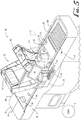
- FIG. 4 illustrates one such alternate system 100 with pole-mounted indicator lights 80, 90.
- Light 84 is disposed atop pole 82 and light 94 is disposed atop pole 92. In such a raised position, the lights 84, 94 may be in a more visible position to the user.
- the poles 82, 92 themselves may comprise lighted elements.
- one or more lighting elements 160, 170 are mounted or disposed in the trailing arch section 16, each lighting element 160, 170 projecting a light spot or light curtain down onto the exit conveyor 32 alighting the item 46 (and/or 48) with a green or red light indicating a good read or an exception in similar fashion as in the prior embodiments.
- a series of lighting elements 160, 170 may be positioned on the trailing arch section 16, each lighting element alighting a different section of the exit belt 32 along the indicator location 27 for alighting multiple overlapping items.
- lighting element 160 may project a (e.g., red or green color) light spot or curtain 162 on one side of the conveyor 32 for alighting the item 46
- lighting element 170 may project a (e.g., red or green) light spot or curtain 172 for alighting item 48.
- Fig. 6 illustrates another example system 300 having one or more light projection elements mounted or disposed in a separate arch structure 302 positioned downstream of the portal data reader 12.
- the arch structure 302 includes right and left leg sections 304, 306 supporting an upper central section 308 spanning the exit conveyor section 32.
- Each of the light projection components projects a light spot or light curtain down onto the exit conveyor section 32 alighting the item 46 (and/or item 48) with a green or red (or some other color) light indicating a good read or an exception in similar fashion as in the prior embodiments.
- a series of lighting elements may be positioned in or on the arch 302, each lighting element alighting a different section of the exit belt 32 along the indicator location 27.
- first lighting element 310 may project a light spot or curtain 311 (red or green) on one side of the belt 32 for alighting the item 46
- second lighting element 312 may project a light spot or curtain 313 (red or green) for alighting item 48
- third lighting element 314 may project a light spot or curtain 315 (red or green) for alighting a third item.
- Fig. 7 illustrates another example system 350 having one or more light projection elements mounted or disposed in a separate arch (or overhanging post) structure 352 positioned downstream of the portal data reader 12.
- the structure 352 includes a single post or leg section 354 supported/attached to the outlet end 24 of the housing/counter opposite the user 3, and an upper section 356 spanning above the exit conveyor section 32.
- Each of the light projection components projects a light spot or light curtain down onto the exit conveyor 32 alighting the item 46 (and/or 48) with a green or red light indicating a good read or an exception in similar fashion as in the prior embodiments.
- a series of lighting elements may be positioned in or on the arch 352, each lighting element alighting a different section of the exit belt 32 along the indicator location 27.
- multiple light projection elements may be provided. In the example of Fig.
- first lighting element 360 may project a light spot or curtain 361 (red or green) on one side of the belt 32 for alighting the item 46
- second lighting element 362 may project a light spot or curtain 363 (red or green) for alighting item 48
- third lighting element 364 may project a light spot or curtain 365 (red or green) for alighting a third item.
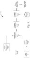
- Fig. 8 is a flowchart of an item handling and indicator method 200 according to one embodiment, comprising the following steps. For further description, the method steps are described with reference to elements of the system 10 and portal data reader 12 relative to item 46 as illustrated in the example of Fig. 1 .
- Step 202 placing the item 46 on the inlet end 30 of the (moving) conveyor 30/32.
- Step 204 via the conveyor 30/32, moving the item 46 through the portal data reader 12.
- Step 206 via the portal data reader 12, capturing information about the item, information may include:
- the system 10 may track the movement of the item through the portal data reader 12.
- Step 208 via the portal data reader 12, attempting to capture optical code information from the item 46. If successful in capturing and reading/decoding, proceeding to Step 216; if unsuccessful, proceeding to Step 210 (or directly to Step 212 if the system does not include object recognition).
- Step 210 via the portal data reader 12, attempting to identify the item using object recognition techniques such as visual pattern recognition. If YES, proceeding to Step 216; if NO, proceeding to Step 212 (Exception handing). Step 210 is omitted if the system is not provided with object recognition capability.
- object recognition techniques such as visual pattern recognition.
- Step 212 from an unsuccessful identification (from Step 208 and/or Step 210), alighting the indicator lights 60, 65 in red from a moment when a leading edge of the item 46 reaches the indicator location 27 until the trailing edge of the item 46 passes the indicator location 27.
- Step 214 clearing the exception, for example, exception clearing may be accomplished by one or more of the following options:
- Step 216 from a successful item identification from either Step 208 or Step 210, alighting the indicator lights 60, 65 in green from a moment when a leading edge of the item 46 reaches the indicator location 27 until the trailing edge of the item 46 passes the indicator location 27 and sending data acquired from the optical code and/or item information to the POS system; proceeding to Step 218.
- Step 218 via the downstream conveyor section 32, moving the item to the bagging area 39.
- Fig. 9 illustrates another checkout system 250 having a series of lights arranged at a suitable location along the side rails proximate the exit end 32.
- the system 250 has on the left rail a series of lights 252, 253, 254, etc. along the top side of the left rail and corresponding lights 252b, 253b, 254b, 255b, 256b, 257b, 258b, etc. along the outside of the left rail and a series of corresponding lights (not visible in the figure but similar to the lights 262a, 263a, 264a of the right side rail) along the inside of the left rail.
- the right side rail has a series of lights 262, 263, 264, 265, 266, 267, 268, etc.
- a light As an item, such as item 46, exits read zone of the portal data reader 12, corresponding lights along the side rails alight, the number of lights corresponding to the length of the item (from leading edge to trailing edge) and in a color (e.g., red or green) corresponding to whether the item 46 was identified by the portal data reader 12.
- a band of lights the number of adjacent lights corresponding to the length of the item 46
- Fig. 9 also illustrates an alternate exception handling system comprised of a diverter 280 operable to pivot from one side to the other so as to divert the item along a desired path to either the first exit path 282 or second exit path 284.
- the diverter is either (1) moved to a first position as shown in Fig. 9 directing items that have been successfully identified toward the user and along the first exit path 282 where they can be bagged or otherwise taken by the user as purchased, or (2) moved to a second position for directing items that have not been successfully identified by the portal data reader 12 away from the user and along the second item path 284 for further exception handling.
Landscapes
- Physics & Mathematics (AREA)
- Engineering & Computer Science (AREA)
- Business, Economics & Management (AREA)
- General Physics & Mathematics (AREA)
- Economics (AREA)
- Theoretical Computer Science (AREA)
- Quality & Reliability (AREA)
- Strategic Management (AREA)
- General Business, Economics & Management (AREA)
- Tourism & Hospitality (AREA)
- Electromagnetism (AREA)
- Operations Research (AREA)
- Development Economics (AREA)
- Marketing (AREA)
- Entrepreneurship & Innovation (AREA)
- Human Resources & Organizations (AREA)
- Computer Vision & Pattern Recognition (AREA)
- Artificial Intelligence (AREA)
- Health & Medical Sciences (AREA)
- General Health & Medical Sciences (AREA)
- Geometry (AREA)
- Toxicology (AREA)
- Accounting & Taxation (AREA)
- Finance (AREA)
- Cash Registers Or Receiving Machines (AREA)
Claims (13)
- Automatisiertes Checkout-System, umfassend:einen Datenleser (12) mit einer Lesezone (13), wobei der Datenleser (12) betreibbar ist, um Artikel zu identifizieren, die durch die Lesezone (13) befördert werden;ein Fördersystem (30/32) mit einer Eingabezone und einer Ausgabezone, wobei das Fördersystem (30/32) konfiguriert ist, um die Artikel automatisch von der Eingabezone durch die Lesezone (13) des Datenlesers (12) und zu der Ausgabezone zu befördern; undein Beleuchtungsanzeigesystem, das eine gegebene Farbe als Reaktion auf eine Eingabe von dem Datenleser (12) erleuchtet;dadurch gekennzeichnet, dassdas Beleuchtungsanzeigesystem an einem Anzeigeort (27) nahe der Ausgabezone des Fördersystems (30/32) angeordnet ist, wobei das Beleuchtungsanzeigesystem einschaltet, wenn der Artikel (42-48) den Anzeigeort (27) erreicht oder in diesen eintritt; unddas Beleuchtungsanzeigesystem betriebsfähig ist, um einzuschalten, wenn ein vorderer Abschnitt des Artikels (42-48) den Anzeigeort (27) erreicht, und dann auszuschalten, wenn ein hinterer Abschnitt des Artikels (42-48) den Anzeigeort (27) erreicht, oder das Beleuchtungsanzeigesystem betriebsfähig ist, um kontinuierlich einzuschalten und zu erleuchten, wenn ein vorderer Abschnitt des Artikels (42-48) den Anzeigeort (27) erreicht.
- System (10) nach Anspruch 1, wobei der Datenleser (12) ein optisches Codelesesystem einschließt, das zum Lesen optischer Codes auf den Artikeln betreibbar ist, um die Artikel zu identifizieren, die durch die Lesezone (13) befördert werden, oder wobei der Datenleser (12) ein optisches Erkennungssystem einschließt, das zum Verwenden optischer Erkennung betreibbar ist, um die Artikel zu identifizieren, die durch die Lesezone (13) befördert werden.
- System (10) nach Anspruch 1, ferner umfassend eine Steuerung, die betriebsfähig ist, um (a) ein erstes Signal zu erzeugen, das einer erfolgreichen Identifizierung eines durch die Lesezone (13) beförderten Artikels (48) entspricht, und (b) ein zweites Signal zu erzeugen, das einer erfolglosen Identifizierung des durch die Lesezone (13) beförderten Artikels (46) entspricht, wobei als Reaktion auf das erste Signal die Beleuchtungsanzeige eine erste Farbe erleuchtet, die der erfolgreichen Identifizierung entspricht, wobei als Reaktion auf das zweite Signal die Beleuchtungsanzeige eine zweite Farbe erleuchtet, die der erfolglosen Identifizierung entspricht, wobei vorzugsweise die erste Farbe grün ist und die zweite Farbe rot ist.
- System (10) nach Anspruch 1, ferner umfassend ein Bildgebungssystem und einen Anzeigebildschirm (50), wobei das Bildgebungssystem zum Erfassen eines Bildes des Artikels (42-48) zum Senden an den Anzeigebildschirm (50) betriebsfähig ist.
- System (10) nach Anspruch 1, wobei die Beleuchtungsanzeige Anzeigelampen (60, 65, 80, 90) umfasst, die in oder an Seitenschienen (24a, 24b) an gegenüberliegenden Seiten des Fördersystems (30/32) in der Ausgabezone angeordnet sind, wobei die Anzeigelampen (80, 90) vorzugsweise an Pfosten (82, 89) angeordnet sind, die sich von den Seitenschienen (24a, 24b) nach oben erstrecken.
- System (10) nach Anspruch 1, wobei das Beleuchtungsanzeigesystem eine Beleuchtungsquelle umfasst, die über der Fördereinrichtung (32) angeordnet ist und betriebsfähig ist, um einen Lichtstrahl oder -vorhang (311, 313, 315, 361, 363, 365) nach unten auf den Artikel (42-48) an dem Anzeigeort (27) zu projizieren, wodurch zumindest ein Abschnitt des Artikels (42-48) mit einem Licht der gegebenen Farbe erleuchtet wird.
- System nach Anspruch 1, ferner umfassend ein Anzeigesystem für erfolgreiches Lesen, umfassend ein Beleuchtungssystem, das zum Projizieren von Lichtstrahlen einer ausgewählten Vielzahl verschiedenfarbiger Strahlen auf oder in die Nähe der Artikel betreibbar ist, wobei die ausgewählte Farbe für einen Lichtstrahl, der auf einen Artikel projiziert wird, davon abhängt, ob der Artikel (42-48) erfolgreich durch den Datenleser (12) identifiziert wurde.
- Betriebsverfahren für ein automatisiertes Checkout-System, umfassend die Schritte: Befördern von Artikeln über ein Fördersystem (30/32) entlang eines Artikelpfads durch eine Lesezone (13) eines Datenlesers (12) und zu einer Ausgabezone;und
Verfolgen eines ersten Artikels (48) über ein Ortungssystem, während er entlang des Artikelpfads bewegt wird;
Versuchen, über den Datenleser (12) den ersten Artikel (48) durch Lesen eines optischen Codes auf dem ersten Artikel (48) zu identifizieren, während er durch die Lesezone (13) befördert wird; und
Erleuchten einer Anzeigelampe (60, 65, 80, 90) in einer gegebenen Farbe als Reaktion auf eine Eingabe von dem Datenleser (12);
gekennzeichnet durch
die Anzeigelampe (60, 65, 80, 90), die sich an einem Anzeigeort (27) in der Ausgabezone des Fördersystems (30/32) befindet, wobei die Anzeigelampe (60, 65, 80, 90) erleuchtet, wenn der erste Artikel (48) den Anzeigeort (27) erreicht oder in diesen eintritt; und
Einschalten der Anzeigelampe (60), wenn ein vorderer Abschnitt des Artikels (48) den Anzeigeort (27) erreicht, und dann Ausschalten, wenn ein hinterer Abschnitt des Artikels (48) den Anzeigeort (27) erreicht, oder kontinuierliches Erleuchten mit der Anzeigelampe (60, 65, 80, 90), wenn der vordere Abschnitt des Artikels (48) den Anzeigeort (27) erreicht. - Verfahren nach Anspruch 8, wobei die Anzeigelampe (60, 65, 80, 90) eine gegebene Farbe entsprechend einer Eingabe von dem Datenleser (12) erleuchtet, wobei vorzugsweise die Anzeigelampe (60, 65, 80, 90) eine gegebene erste Farbe erleuchtet, wenn der Datenleser (12) den ersten Artikel (48) erfolgreich identifiziert; und die Anzeigelampe (60, 65, 80, 90) eine gegebene zweite Farbe erleuchtet, wenn der Datenleser (12) den ersten Artikel (48) nicht identifiziert.
- Verfahren nach Anspruch 8, ferner umfassend das Bestimmen einer Ausnahme der Artikelidentifizierung, wenn der Datenleser (12) den ersten Artikel (48) nicht identifiziert.
- Verfahren nach Anspruch 10, wobei der Schritt des Bestimmens einer Ausnahme der Artikelidentifizierung das Versuchen einschließt, den ersten Artikel (48) mit dem Datenleser (12) durch Lesen eines optischen Codes auf dem ersten Artikel (48) zu identifizieren, oder wobei der Schritt des Bestimmens einer Ausnahme der Artikelidentifizierung ferner das Versuchen einschließt, den ersten Artikel (48) mit dem Datenleser (12) durch Verwenden optischer Erkennung zum Identifizieren des ersten Artikels (48) zu identifizieren.
- Verfahren nach Anspruch 8, ferner umfassend
Verfolgen eines zweiten Artikels (46) über das Ortungssystem, während er neben dem ersten Artikel (48) und entlang des Artikelpfads befördert wird;
Versuchen, über den Datenleser (12), den zweiten Artikel (46) zu identifizieren, der durch die Lesezone (13) befördert wird;
Erleuchten einer zweiten Anzeigelampe, die an einem Anzeigeort (27) in der Ausgabezone des Fördersystems (30/32) angeordnet ist, wobei die Anzeigelampe (60, 65, 80, 90) erleuchtet, sobald der zweite Artikel (46) den Anzeigeort (27) erreicht. - Verfahren nach Anspruch 12, wobei die Anzeigelampe (60) einschaltet, wenn ein vorderer Abschnitt des zweiten Artikels (46) den Anzeigeort (27) erreicht, und wobei die Anzeigelampe (60) ausschaltet, wenn ein hinterer Abschnitt des zweiten Artikels (46) den Anzeigeort (27) erreicht.
Applications Claiming Priority (3)
| Application Number | Priority Date | Filing Date | Title |
|---|---|---|---|
| US201261673145P | 2012-07-18 | 2012-07-18 | |
| US13/942,620 US9378397B2 (en) | 2012-07-18 | 2013-07-15 | Portal data reader indicator light control |
| PCT/US2013/050925 WO2014015058A1 (en) | 2012-07-18 | 2013-07-17 | Portal data reader indicator light control |
Publications (3)
| Publication Number | Publication Date |
|---|---|
| EP2874924A1 EP2874924A1 (de) | 2015-05-27 |
| EP2874924A4 EP2874924A4 (de) | 2016-03-16 |
| EP2874924B1 true EP2874924B1 (de) | 2021-01-06 |
Family
ID=49945717
Family Applications (1)
| Application Number | Title | Priority Date | Filing Date |
|---|---|---|---|
| EP13819750.4A Active EP2874924B1 (de) | 2012-07-18 | 2013-07-17 | Blinklichtsteuerung für portaldatenleser |
Country Status (3)
| Country | Link |
|---|---|
| US (1) | US9378397B2 (de) |
| EP (1) | EP2874924B1 (de) |
| WO (1) | WO2014015058A1 (de) |
Families Citing this family (17)
| Publication number | Priority date | Publication date | Assignee | Title |
|---|---|---|---|---|
| EP2960190B1 (de) * | 2014-06-23 | 2018-01-03 | Wincor Nixdorf International GmbH | Packmuldensystem für ein warencheckout-system |
| US9898635B2 (en) * | 2014-12-30 | 2018-02-20 | Hand Held Products, Inc. | Point-of-sale (POS) code sensing apparatus |
| US20160224227A1 (en) * | 2015-01-29 | 2016-08-04 | Caterpillar Inc. | Indication Display System |
| US9690967B1 (en) | 2015-10-29 | 2017-06-27 | Digimarc Corporation | Detecting conflicts between multiple different encoded signals within imagery |
| US10262176B1 (en) | 2016-02-23 | 2019-04-16 | Digimarc Corporation | Scanner with control logic for resolving package labeling |
| US10198782B1 (en) | 2016-09-15 | 2019-02-05 | Digimarc Corporation | Detecting conflicts between multiple different encoded signals within imagery |
| US20190238796A1 (en) | 2017-05-11 | 2019-08-01 | Jacob Nathaniel Allen | Object Inspection System And Method For Inspecting An Object |
| JP2019008759A (ja) * | 2017-06-28 | 2019-01-17 | 株式会社 コリアセブン | 無人計算装置、その制御方法及びコンピュータプログラム、並びに無人計算装置の制御装置 |
| CN107403121A (zh) * | 2017-07-05 | 2017-11-28 | 中国科学院合肥物质科学研究院 | 一种农资产品快速扫码装置 |
| TWI652634B (zh) * | 2018-01-31 | 2019-03-01 | 緯創資通股份有限公司 | 自助結帳方法及其系統 |
| US10401303B1 (en) * | 2018-08-15 | 2019-09-03 | P & P Optica Inc. | Lighting apparatus for conveyors |
| CN110969032B (zh) * | 2018-09-28 | 2023-09-05 | 捷普电子(广州)有限公司 | 用于扫描物体的扫描设备 |
| RU2716298C1 (ru) * | 2019-10-21 | 2020-03-11 | Сергей Васильевич Черненко | Кассовый бокс с виртуальным автоматическим разделителем покупок и способ управления им |
| DE102019134064A1 (de) | 2019-12-12 | 2021-06-17 | Sick Ag | Lesen einer Vielzahl von Codes |
| KR20230024390A (ko) | 2020-06-17 | 2023-02-20 | 이노비전 소프트웨어 솔루션즈, 인크. | 결함 복원을 위한 시스템 및 방법 |
| US12293506B2 (en) | 2021-07-20 | 2025-05-06 | Inovision Software Solutions, Inc. | Method to locate defects in e-coat |
| US12475342B2 (en) | 2023-07-28 | 2025-11-18 | Zebra Technologies Corporation | Systems and methods for changing an aimer blink pattern responsive to a decode event |
Family Cites Families (22)
| Publication number | Priority date | Publication date | Assignee | Title |
|---|---|---|---|---|
| US4676343A (en) | 1984-07-09 | 1987-06-30 | Checkrobot Inc. | Self-service distribution system |
| US4679154A (en) | 1985-07-09 | 1987-07-07 | Ncr Corporation | Scanning control system for merchandise checkout |
| JP2684739B2 (ja) | 1988-12-29 | 1997-12-03 | いすゞ自動車株式会社 | コンベアへの塔載位置指示装置 |
| US6332575B1 (en) * | 1997-10-31 | 2001-12-25 | Symbol Technologies, Inc. | Audible indicators for optical code reading systems |
| US5491328A (en) | 1991-09-24 | 1996-02-13 | Spectra-Physics Scanning Systems, Inc. | Checkout counter scanner having multiple scanning surfaces |
| US6554189B1 (en) | 1996-10-07 | 2003-04-29 | Metrologic Instruments, Inc. | Automated system and method for identifying and measuring packages transported through a laser scanning tunnel |
| US7311260B2 (en) * | 2002-01-18 | 2007-12-25 | Microscan Systems Incorporated | Camera positioning and confirmation feedback system |
| US7246745B2 (en) | 2004-02-27 | 2007-07-24 | Evolution Robotics Retail, Inc. | Method of merchandising for checkout lanes |
| US7337960B2 (en) | 2004-02-27 | 2008-03-04 | Evolution Robotics, Inc. | Systems and methods for merchandise automatic checkout |
| US7780081B1 (en) | 2005-01-03 | 2010-08-24 | RCL Products, Inc. | System and method for security protection, inventory tracking and automated shopping cart checkout |
| US7334729B2 (en) * | 2006-01-06 | 2008-02-26 | International Business Machines Corporation | Apparatus, system, and method for optical verification of product information |
| US8061605B2 (en) | 2007-02-13 | 2011-11-22 | Production Resource Group, L.L.C. | RFID monitor |
| US7942329B2 (en) * | 2007-08-14 | 2011-05-17 | Jadak, Llc | Method for providing user feedback in an autoidentification system |
| EP2212827B1 (de) | 2007-10-16 | 2019-09-11 | Accu-Sort System, Inc. | Dimensionierungs- und strichcode-lesesystem |
| US20100140357A1 (en) | 2008-12-09 | 2010-06-10 | Thomas Roslak | Point-of-transaction checkout system |
| US8571298B2 (en) * | 2008-12-23 | 2013-10-29 | Datalogic ADC, Inc. | Method and apparatus for identifying and tallying objects |
| US8494909B2 (en) * | 2009-02-09 | 2013-07-23 | Datalogic ADC, Inc. | Automatic learning in a merchandise checkout system with visual recognition |
| US8733643B2 (en) | 2011-01-24 | 2014-05-27 | Datalogic ADC, Inc. | Systems and methods for providing feedback to a user operating an automated checkstand |
| CN103443803B (zh) | 2011-01-24 | 2017-04-26 | 数据逻辑Adc公司 | 用于自动化检验的隧道或入口扫描器和扫描的方法 |
| US8939369B2 (en) | 2011-01-24 | 2015-01-27 | Datalogic ADC, Inc. | Exception detection and handling in automated optical code reading systems |
| US20120187195A1 (en) | 2011-01-24 | 2012-07-26 | Datalogic ADC, Inc. | Systems and methods for reading encoded data through gaps between conveyors in an automated checkout system |
| US9552507B2 (en) | 2012-05-07 | 2017-01-24 | Datalogic Usa, Inc. | System and method for reading optical codes on bottom surface of items |
-
2013
- 2013-07-15 US US13/942,620 patent/US9378397B2/en active Active
- 2013-07-17 WO PCT/US2013/050925 patent/WO2014015058A1/en not_active Ceased
- 2013-07-17 EP EP13819750.4A patent/EP2874924B1/de active Active
Non-Patent Citations (1)
| Title |
|---|
| None * |
Also Published As
| Publication number | Publication date |
|---|---|
| EP2874924A1 (de) | 2015-05-27 |
| EP2874924A4 (de) | 2016-03-16 |
| US20140021260A1 (en) | 2014-01-23 |
| US9378397B2 (en) | 2016-06-28 |
| WO2014015058A1 (en) | 2014-01-23 |
Similar Documents
| Publication | Publication Date | Title |
|---|---|---|
| EP2874924B1 (de) | Blinklichtsteuerung für portaldatenleser | |
| CN103430190B (zh) | 提供反馈给操作自动点货收款台的用户的系统和方法 | |
| US9082142B2 (en) | Using a mobile device to assist in exception handling in self-checkout and automated data capture systems | |
| EP2873044B1 (de) | Verfahren und system zur verarbeitung von kunden durch ein kassenterminalsystem mit preisscanvorrichtung für mehrere artikel | |
| CN103443802B (zh) | 用于读取光学代码的系统和方法 | |
| US20250225845A1 (en) | Bioptical Barcode Reader | |
| EP2847710B1 (de) | System und verfahren zum lesen optischer codes auf der unterseite von gegenständen | |
| US8925815B2 (en) | Checkout system for and method of preventing a customer-operated accessory reader facing a bagging area from imaging targets on products passed through a clerk-operated workstation to the bagging area | |
| US12488381B2 (en) | Retail store self-checkout station and related methods for providing interactive virtual lane for smart self-checkouts | |
| JP7771491B2 (ja) | 会計システム | |
| JP2016110536A (ja) | 商品処理システム及び商品処理方法 | |
| EP3474181A1 (de) | Vorrichtung zur automatischen erkennung von produkten | |
| US20180293567A1 (en) | A checkout counter and a registration area of a checkout counter | |
| JP7336332B2 (ja) | 商品情報読取装置、商品情報読取方法 | |
| EP3018612B1 (de) | System und verfahren zur automatischen vermeidung von signalinterferenz zwischen produkt-proximity-subsystemen, die signale durch gegenüberstehende präsentationsfenster von verschiedenen arbeitsstationen aussenden | |
| WO2015167858A1 (en) | Barcode imaging workstation having sequentially activated object sensors | |
| US20190066453A1 (en) | Dual checkout system | |
| KR20260033801A (ko) | 스마트 카트를 이용한 터널형 무인 계산 시스템 |
Legal Events
| Date | Code | Title | Description |
|---|---|---|---|
| PUAI | Public reference made under article 153(3) epc to a published international application that has entered the european phase |
Free format text: ORIGINAL CODE: 0009012 |
|
| 17P | Request for examination filed |
Effective date: 20150116 |
|
| AK | Designated contracting states |
Kind code of ref document: A1 Designated state(s): AL AT BE BG CH CY CZ DE DK EE ES FI FR GB GR HR HU IE IS IT LI LT LU LV MC MK MT NL NO PL PT RO RS SE SI SK SM TR |
|
| AX | Request for extension of the european patent |
Extension state: BA ME |
|
| DAX | Request for extension of the european patent (deleted) | ||
| RA4 | Supplementary search report drawn up and despatched (corrected) |
Effective date: 20160217 |
|
| RIC1 | Information provided on ipc code assigned before grant |
Ipc: G06T 7/00 20060101ALI20160211BHEP Ipc: G06Q 20/20 20120101ALI20160211BHEP Ipc: B65G 43/00 20060101ALI20160211BHEP Ipc: B65G 47/49 20060101AFI20160211BHEP Ipc: G06Q 10/08 20120101ALI20160211BHEP Ipc: G06K 17/00 20060101ALI20160211BHEP Ipc: G07G 1/00 20060101ALI20160211BHEP Ipc: G06K 7/10 20060101ALI20160211BHEP Ipc: G09F 19/00 20060101ALI20160211BHEP |
|
| RAP1 | Party data changed (applicant data changed or rights of an application transferred) |
Owner name: DATALOGIC USA, INC. |
|
| REG | Reference to a national code |
Ref country code: DE Ref legal event code: R079 Ref document number: 602013075195 Country of ref document: DE Free format text: PREVIOUS MAIN CLASS: B65G0047490000 Ipc: A47F0009040000 |
|
| RIC1 | Information provided on ipc code assigned before grant |
Ipc: G06K 7/10 20060101ALI20200623BHEP Ipc: G07G 1/00 20060101ALI20200623BHEP Ipc: G06Q 10/08 20120101ALI20200623BHEP Ipc: A47F 9/04 20060101AFI20200623BHEP |
|
| GRAP | Despatch of communication of intention to grant a patent |
Free format text: ORIGINAL CODE: EPIDOSNIGR1 |
|
| STAA | Information on the status of an ep patent application or granted ep patent |
Free format text: STATUS: GRANT OF PATENT IS INTENDED |
|
| INTG | Intention to grant announced |
Effective date: 20200806 |
|
| GRAS | Grant fee paid |
Free format text: ORIGINAL CODE: EPIDOSNIGR3 |
|
| GRAA | (expected) grant |
Free format text: ORIGINAL CODE: 0009210 |
|
| STAA | Information on the status of an ep patent application or granted ep patent |
Free format text: STATUS: THE PATENT HAS BEEN GRANTED |
|
| AK | Designated contracting states |
Kind code of ref document: B1 Designated state(s): AL AT BE BG CH CY CZ DE DK EE ES FI FR GB GR HR HU IE IS IT LI LT LU LV MC MK MT NL NO PL PT RO RS SE SI SK SM TR |
|
| REG | Reference to a national code |
Ref country code: GB Ref legal event code: FG4D |
|
| REG | Reference to a national code |
Ref country code: AT Ref legal event code: REF Ref document number: 1351382 Country of ref document: AT Kind code of ref document: T Effective date: 20210115 Ref country code: CH Ref legal event code: EP |
|
| REG | Reference to a national code |
Ref country code: DE Ref legal event code: R096 Ref document number: 602013075195 Country of ref document: DE |
|
| REG | Reference to a national code |
Ref country code: IE Ref legal event code: FG4D |
|
| REG | Reference to a national code |
Ref country code: NL Ref legal event code: MP Effective date: 20210106 |
|
| REG | Reference to a national code |
Ref country code: AT Ref legal event code: MK05 Ref document number: 1351382 Country of ref document: AT Kind code of ref document: T Effective date: 20210106 |
|
| REG | Reference to a national code |
Ref country code: LT Ref legal event code: MG9D |
|
| PG25 | Lapsed in a contracting state [announced via postgrant information from national office to epo] |
Ref country code: LT Free format text: LAPSE BECAUSE OF FAILURE TO SUBMIT A TRANSLATION OF THE DESCRIPTION OR TO PAY THE FEE WITHIN THE PRESCRIBED TIME-LIMIT Effective date: 20210106 Ref country code: PT Free format text: LAPSE BECAUSE OF FAILURE TO SUBMIT A TRANSLATION OF THE DESCRIPTION OR TO PAY THE FEE WITHIN THE PRESCRIBED TIME-LIMIT Effective date: 20210506 Ref country code: HR Free format text: LAPSE BECAUSE OF FAILURE TO SUBMIT A TRANSLATION OF THE DESCRIPTION OR TO PAY THE FEE WITHIN THE PRESCRIBED TIME-LIMIT Effective date: 20210106 Ref country code: FI Free format text: LAPSE BECAUSE OF FAILURE TO SUBMIT A TRANSLATION OF THE DESCRIPTION OR TO PAY THE FEE WITHIN THE PRESCRIBED TIME-LIMIT Effective date: 20210106 Ref country code: GR Free format text: LAPSE BECAUSE OF FAILURE TO SUBMIT A TRANSLATION OF THE DESCRIPTION OR TO PAY THE FEE WITHIN THE PRESCRIBED TIME-LIMIT Effective date: 20210407 Ref country code: BG Free format text: LAPSE BECAUSE OF FAILURE TO SUBMIT A TRANSLATION OF THE DESCRIPTION OR TO PAY THE FEE WITHIN THE PRESCRIBED TIME-LIMIT Effective date: 20210406 Ref country code: NO Free format text: LAPSE BECAUSE OF FAILURE TO SUBMIT A TRANSLATION OF THE DESCRIPTION OR TO PAY THE FEE WITHIN THE PRESCRIBED TIME-LIMIT Effective date: 20210406 Ref country code: NL Free format text: LAPSE BECAUSE OF FAILURE TO SUBMIT A TRANSLATION OF THE DESCRIPTION OR TO PAY THE FEE WITHIN THE PRESCRIBED TIME-LIMIT Effective date: 20210106 |
|
| PG25 | Lapsed in a contracting state [announced via postgrant information from national office to epo] |
Ref country code: SE Free format text: LAPSE BECAUSE OF FAILURE TO SUBMIT A TRANSLATION OF THE DESCRIPTION OR TO PAY THE FEE WITHIN THE PRESCRIBED TIME-LIMIT Effective date: 20210106 Ref country code: AT Free format text: LAPSE BECAUSE OF FAILURE TO SUBMIT A TRANSLATION OF THE DESCRIPTION OR TO PAY THE FEE WITHIN THE PRESCRIBED TIME-LIMIT Effective date: 20210106 Ref country code: RS Free format text: LAPSE BECAUSE OF FAILURE TO SUBMIT A TRANSLATION OF THE DESCRIPTION OR TO PAY THE FEE WITHIN THE PRESCRIBED TIME-LIMIT Effective date: 20210106 Ref country code: PL Free format text: LAPSE BECAUSE OF FAILURE TO SUBMIT A TRANSLATION OF THE DESCRIPTION OR TO PAY THE FEE WITHIN THE PRESCRIBED TIME-LIMIT Effective date: 20210106 Ref country code: LV Free format text: LAPSE BECAUSE OF FAILURE TO SUBMIT A TRANSLATION OF THE DESCRIPTION OR TO PAY THE FEE WITHIN THE PRESCRIBED TIME-LIMIT Effective date: 20210106 |
|
| PG25 | Lapsed in a contracting state [announced via postgrant information from national office to epo] |
Ref country code: IS Free format text: LAPSE BECAUSE OF FAILURE TO SUBMIT A TRANSLATION OF THE DESCRIPTION OR TO PAY THE FEE WITHIN THE PRESCRIBED TIME-LIMIT Effective date: 20210506 |
|
| REG | Reference to a national code |
Ref country code: DE Ref legal event code: R097 Ref document number: 602013075195 Country of ref document: DE |
|
| PG25 | Lapsed in a contracting state [announced via postgrant information from national office to epo] |
Ref country code: SM Free format text: LAPSE BECAUSE OF FAILURE TO SUBMIT A TRANSLATION OF THE DESCRIPTION OR TO PAY THE FEE WITHIN THE PRESCRIBED TIME-LIMIT Effective date: 20210106 Ref country code: CZ Free format text: LAPSE BECAUSE OF FAILURE TO SUBMIT A TRANSLATION OF THE DESCRIPTION OR TO PAY THE FEE WITHIN THE PRESCRIBED TIME-LIMIT Effective date: 20210106 Ref country code: EE Free format text: LAPSE BECAUSE OF FAILURE TO SUBMIT A TRANSLATION OF THE DESCRIPTION OR TO PAY THE FEE WITHIN THE PRESCRIBED TIME-LIMIT Effective date: 20210106 |
|
| PLBE | No opposition filed within time limit |
Free format text: ORIGINAL CODE: 0009261 |
|
| STAA | Information on the status of an ep patent application or granted ep patent |
Free format text: STATUS: NO OPPOSITION FILED WITHIN TIME LIMIT |
|
| PG25 | Lapsed in a contracting state [announced via postgrant information from national office to epo] |
Ref country code: ES Free format text: LAPSE BECAUSE OF FAILURE TO SUBMIT A TRANSLATION OF THE DESCRIPTION OR TO PAY THE FEE WITHIN THE PRESCRIBED TIME-LIMIT Effective date: 20210106 Ref country code: DK Free format text: LAPSE BECAUSE OF FAILURE TO SUBMIT A TRANSLATION OF THE DESCRIPTION OR TO PAY THE FEE WITHIN THE PRESCRIBED TIME-LIMIT Effective date: 20210106 Ref country code: RO Free format text: LAPSE BECAUSE OF FAILURE TO SUBMIT A TRANSLATION OF THE DESCRIPTION OR TO PAY THE FEE WITHIN THE PRESCRIBED TIME-LIMIT Effective date: 20210106 Ref country code: SK Free format text: LAPSE BECAUSE OF FAILURE TO SUBMIT A TRANSLATION OF THE DESCRIPTION OR TO PAY THE FEE WITHIN THE PRESCRIBED TIME-LIMIT Effective date: 20210106 |
|
| 26N | No opposition filed |
Effective date: 20211007 |
|
| PG25 | Lapsed in a contracting state [announced via postgrant information from national office to epo] |
Ref country code: AL Free format text: LAPSE BECAUSE OF FAILURE TO SUBMIT A TRANSLATION OF THE DESCRIPTION OR TO PAY THE FEE WITHIN THE PRESCRIBED TIME-LIMIT Effective date: 20210106 |
|
| PG25 | Lapsed in a contracting state [announced via postgrant information from national office to epo] |
Ref country code: SI Free format text: LAPSE BECAUSE OF FAILURE TO SUBMIT A TRANSLATION OF THE DESCRIPTION OR TO PAY THE FEE WITHIN THE PRESCRIBED TIME-LIMIT Effective date: 20210106 |
|
| REG | Reference to a national code |
Ref country code: CH Ref legal event code: PL |
|
| GBPC | Gb: european patent ceased through non-payment of renewal fee |
Effective date: 20210717 |
|
| PG25 | Lapsed in a contracting state [announced via postgrant information from national office to epo] |
Ref country code: MC Free format text: LAPSE BECAUSE OF FAILURE TO SUBMIT A TRANSLATION OF THE DESCRIPTION OR TO PAY THE FEE WITHIN THE PRESCRIBED TIME-LIMIT Effective date: 20210106 |
|
| REG | Reference to a national code |
Ref country code: BE Ref legal event code: MM Effective date: 20210731 |
|
| PG25 | Lapsed in a contracting state [announced via postgrant information from national office to epo] |
Ref country code: LI Free format text: LAPSE BECAUSE OF NON-PAYMENT OF DUE FEES Effective date: 20210731 Ref country code: IT Free format text: LAPSE BECAUSE OF FAILURE TO SUBMIT A TRANSLATION OF THE DESCRIPTION OR TO PAY THE FEE WITHIN THE PRESCRIBED TIME-LIMIT Effective date: 20210106 Ref country code: GB Free format text: LAPSE BECAUSE OF NON-PAYMENT OF DUE FEES Effective date: 20210717 Ref country code: CH Free format text: LAPSE BECAUSE OF NON-PAYMENT OF DUE FEES Effective date: 20210731 |
|
| PG25 | Lapsed in a contracting state [announced via postgrant information from national office to epo] |
Ref country code: IS Free format text: LAPSE BECAUSE OF FAILURE TO SUBMIT A TRANSLATION OF THE DESCRIPTION OR TO PAY THE FEE WITHIN THE PRESCRIBED TIME-LIMIT Effective date: 20210506 Ref country code: LU Free format text: LAPSE BECAUSE OF NON-PAYMENT OF DUE FEES Effective date: 20210717 |
|
| PG25 | Lapsed in a contracting state [announced via postgrant information from national office to epo] |
Ref country code: IE Free format text: LAPSE BECAUSE OF NON-PAYMENT OF DUE FEES Effective date: 20210717 Ref country code: BE Free format text: LAPSE BECAUSE OF NON-PAYMENT OF DUE FEES Effective date: 20210731 |
|
| PG25 | Lapsed in a contracting state [announced via postgrant information from national office to epo] |
Ref country code: HU Free format text: LAPSE BECAUSE OF FAILURE TO SUBMIT A TRANSLATION OF THE DESCRIPTION OR TO PAY THE FEE WITHIN THE PRESCRIBED TIME-LIMIT; INVALID AB INITIO Effective date: 20130717 |
|
| PG25 | Lapsed in a contracting state [announced via postgrant information from national office to epo] |
Ref country code: CY Free format text: LAPSE BECAUSE OF FAILURE TO SUBMIT A TRANSLATION OF THE DESCRIPTION OR TO PAY THE FEE WITHIN THE PRESCRIBED TIME-LIMIT Effective date: 20210106 |
|
| P01 | Opt-out of the competence of the unified patent court (upc) registered |
Effective date: 20230528 |
|
| PG25 | Lapsed in a contracting state [announced via postgrant information from national office to epo] |
Ref country code: MK Free format text: LAPSE BECAUSE OF FAILURE TO SUBMIT A TRANSLATION OF THE DESCRIPTION OR TO PAY THE FEE WITHIN THE PRESCRIBED TIME-LIMIT Effective date: 20210106 |
|
| PG25 | Lapsed in a contracting state [announced via postgrant information from national office to epo] |
Ref country code: TR Free format text: LAPSE BECAUSE OF FAILURE TO SUBMIT A TRANSLATION OF THE DESCRIPTION OR TO PAY THE FEE WITHIN THE PRESCRIBED TIME-LIMIT Effective date: 20210106 |
|
| PG25 | Lapsed in a contracting state [announced via postgrant information from national office to epo] |
Ref country code: MT Free format text: LAPSE BECAUSE OF FAILURE TO SUBMIT A TRANSLATION OF THE DESCRIPTION OR TO PAY THE FEE WITHIN THE PRESCRIBED TIME-LIMIT Effective date: 20210106 |
|
| PGFP | Annual fee paid to national office [announced via postgrant information from national office to epo] |
Ref country code: DE Payment date: 20250722 Year of fee payment: 13 |
|
| PGFP | Annual fee paid to national office [announced via postgrant information from national office to epo] |
Ref country code: FR Payment date: 20250725 Year of fee payment: 13 |