EP2875103B1 - Gazéification à deux étages avec double refroidissement - Google Patents
Gazéification à deux étages avec double refroidissement Download PDFInfo
- Publication number
- EP2875103B1 EP2875103B1 EP13810468.2A EP13810468A EP2875103B1 EP 2875103 B1 EP2875103 B1 EP 2875103B1 EP 13810468 A EP13810468 A EP 13810468A EP 2875103 B1 EP2875103 B1 EP 2875103B1
- Authority
- EP
- European Patent Office
- Prior art keywords
- syngas
- reactor
- particulate
- cooled
- temperature
- Prior art date
- Legal status (The legal status is an assumption and is not a legal conclusion. Google has not performed a legal analysis and makes no representation as to the accuracy of the status listed.)
- Active
Links
Images

Classifications
-
- C—CHEMISTRY; METALLURGY
- C10—PETROLEUM, GAS OR COKE INDUSTRIES; TECHNICAL GASES CONTAINING CARBON MONOXIDE; FUELS; LUBRICANTS; PEAT
- C10J—PRODUCTION OF PRODUCER GAS, WATER-GAS, SYNTHESIS GAS FROM SOLID CARBONACEOUS MATERIAL, OR MIXTURES CONTAINING THESE GASES; CARBURETTING AIR OR OTHER GASES
- C10J3/00—Production of combustible gases containing carbon monoxide from solid carbonaceous fuels
- C10J3/72—Other features
- C10J3/721—Multistage gasification, e.g. plural parallel or serial gasification stages
-
- C—CHEMISTRY; METALLURGY
- C10—PETROLEUM, GAS OR COKE INDUSTRIES; TECHNICAL GASES CONTAINING CARBON MONOXIDE; FUELS; LUBRICANTS; PEAT
- C10J—PRODUCTION OF PRODUCER GAS, WATER-GAS, SYNTHESIS GAS FROM SOLID CARBONACEOUS MATERIAL, OR MIXTURES CONTAINING THESE GASES; CARBURETTING AIR OR OTHER GASES
- C10J3/00—Production of combustible gases containing carbon monoxide from solid carbonaceous fuels
- C10J3/46—Gasification of granular or pulverulent flues in suspension
- C10J3/466—Entrained flow processes
-
- C—CHEMISTRY; METALLURGY
- C10—PETROLEUM, GAS OR COKE INDUSTRIES; TECHNICAL GASES CONTAINING CARBON MONOXIDE; FUELS; LUBRICANTS; PEAT
- C10J—PRODUCTION OF PRODUCER GAS, WATER-GAS, SYNTHESIS GAS FROM SOLID CARBONACEOUS MATERIAL, OR MIXTURES CONTAINING THESE GASES; CARBURETTING AIR OR OTHER GASES
- C10J3/00—Production of combustible gases containing carbon monoxide from solid carbonaceous fuels
- C10J3/46—Gasification of granular or pulverulent flues in suspension
- C10J3/48—Apparatus; Plants
- C10J3/485—Entrained flow gasifiers
-
- C—CHEMISTRY; METALLURGY
- C10—PETROLEUM, GAS OR COKE INDUSTRIES; TECHNICAL GASES CONTAINING CARBON MONOXIDE; FUELS; LUBRICANTS; PEAT
- C10J—PRODUCTION OF PRODUCER GAS, WATER-GAS, SYNTHESIS GAS FROM SOLID CARBONACEOUS MATERIAL, OR MIXTURES CONTAINING THESE GASES; CARBURETTING AIR OR OTHER GASES
- C10J3/00—Production of combustible gases containing carbon monoxide from solid carbonaceous fuels
- C10J3/72—Other features
- C10J3/82—Gas withdrawal means
- C10J3/84—Gas withdrawal means with means for removing dust or tar from the gas
-
- C—CHEMISTRY; METALLURGY
- C10—PETROLEUM, GAS OR COKE INDUSTRIES; TECHNICAL GASES CONTAINING CARBON MONOXIDE; FUELS; LUBRICANTS; PEAT
- C10K—PURIFYING OR MODIFYING THE CHEMICAL COMPOSITION OF COMBUSTIBLE GASES CONTAINING CARBON MONOXIDE
- C10K1/00—Purifying combustible gases containing carbon monoxide
- C10K1/002—Removal of contaminants
- C10K1/003—Removal of contaminants of acid contaminants, e.g. acid gas removal
- C10K1/005—Carbon dioxide
-
- C—CHEMISTRY; METALLURGY
- C10—PETROLEUM, GAS OR COKE INDUSTRIES; TECHNICAL GASES CONTAINING CARBON MONOXIDE; FUELS; LUBRICANTS; PEAT
- C10K—PURIFYING OR MODIFYING THE CHEMICAL COMPOSITION OF COMBUSTIBLE GASES CONTAINING CARBON MONOXIDE
- C10K1/00—Purifying combustible gases containing carbon monoxide
- C10K1/02—Dust removal
- C10K1/024—Dust removal by filtration
-
- C—CHEMISTRY; METALLURGY
- C10—PETROLEUM, GAS OR COKE INDUSTRIES; TECHNICAL GASES CONTAINING CARBON MONOXIDE; FUELS; LUBRICANTS; PEAT
- C10K—PURIFYING OR MODIFYING THE CHEMICAL COMPOSITION OF COMBUSTIBLE GASES CONTAINING CARBON MONOXIDE
- C10K1/00—Purifying combustible gases containing carbon monoxide
- C10K1/04—Purifying combustible gases containing carbon monoxide by cooling to condense non-gaseous materials
-
- C—CHEMISTRY; METALLURGY
- C10—PETROLEUM, GAS OR COKE INDUSTRIES; TECHNICAL GASES CONTAINING CARBON MONOXIDE; FUELS; LUBRICANTS; PEAT
- C10K—PURIFYING OR MODIFYING THE CHEMICAL COMPOSITION OF COMBUSTIBLE GASES CONTAINING CARBON MONOXIDE
- C10K1/00—Purifying combustible gases containing carbon monoxide
- C10K1/08—Purifying combustible gases containing carbon monoxide by washing with liquids; Reviving the used wash liquors
- C10K1/10—Purifying combustible gases containing carbon monoxide by washing with liquids; Reviving the used wash liquors with aqueous liquids
- C10K1/101—Purifying combustible gases containing carbon monoxide by washing with liquids; Reviving the used wash liquors with aqueous liquids with water only
-
- C—CHEMISTRY; METALLURGY
- C10—PETROLEUM, GAS OR COKE INDUSTRIES; TECHNICAL GASES CONTAINING CARBON MONOXIDE; FUELS; LUBRICANTS; PEAT
- C10K—PURIFYING OR MODIFYING THE CHEMICAL COMPOSITION OF COMBUSTIBLE GASES CONTAINING CARBON MONOXIDE
- C10K3/00—Modifying the chemical composition of combustible gases containing carbon monoxide to produce an improved fuel, e.g. one of different calorific value, which may be free from carbon monoxide
- C10K3/001—Modifying the chemical composition of combustible gases containing carbon monoxide to produce an improved fuel, e.g. one of different calorific value, which may be free from carbon monoxide by thermal treatment
- C10K3/003—Reducing the tar content
- C10K3/008—Reducing the tar content by cracking
-
- C—CHEMISTRY; METALLURGY
- C10—PETROLEUM, GAS OR COKE INDUSTRIES; TECHNICAL GASES CONTAINING CARBON MONOXIDE; FUELS; LUBRICANTS; PEAT
- C10K—PURIFYING OR MODIFYING THE CHEMICAL COMPOSITION OF COMBUSTIBLE GASES CONTAINING CARBON MONOXIDE
- C10K3/00—Modifying the chemical composition of combustible gases containing carbon monoxide to produce an improved fuel, e.g. one of different calorific value, which may be free from carbon monoxide
- C10K3/02—Modifying the chemical composition of combustible gases containing carbon monoxide to produce an improved fuel, e.g. one of different calorific value, which may be free from carbon monoxide by catalytic treatment
- C10K3/04—Modifying the chemical composition of combustible gases containing carbon monoxide to produce an improved fuel, e.g. one of different calorific value, which may be free from carbon monoxide by catalytic treatment reducing the carbon monoxide content, e.g. water-gas shift [WGS]
-
- C—CHEMISTRY; METALLURGY
- C10—PETROLEUM, GAS OR COKE INDUSTRIES; TECHNICAL GASES CONTAINING CARBON MONOXIDE; FUELS; LUBRICANTS; PEAT
- C10J—PRODUCTION OF PRODUCER GAS, WATER-GAS, SYNTHESIS GAS FROM SOLID CARBONACEOUS MATERIAL, OR MIXTURES CONTAINING THESE GASES; CARBURETTING AIR OR OTHER GASES
- C10J2200/00—Details of gasification apparatus
- C10J2200/09—Mechanical details of gasifiers not otherwise provided for, e.g. sealing means
-
- C—CHEMISTRY; METALLURGY
- C10—PETROLEUM, GAS OR COKE INDUSTRIES; TECHNICAL GASES CONTAINING CARBON MONOXIDE; FUELS; LUBRICANTS; PEAT
- C10J—PRODUCTION OF PRODUCER GAS, WATER-GAS, SYNTHESIS GAS FROM SOLID CARBONACEOUS MATERIAL, OR MIXTURES CONTAINING THESE GASES; CARBURETTING AIR OR OTHER GASES
- C10J2300/00—Details of gasification processes
- C10J2300/09—Details of the feed, e.g. feeding of spent catalyst, inert gas or halogens
- C10J2300/0913—Carbonaceous raw material
- C10J2300/0943—Coke
-
- C—CHEMISTRY; METALLURGY
- C10—PETROLEUM, GAS OR COKE INDUSTRIES; TECHNICAL GASES CONTAINING CARBON MONOXIDE; FUELS; LUBRICANTS; PEAT
- C10K—PURIFYING OR MODIFYING THE CHEMICAL COMPOSITION OF COMBUSTIBLE GASES CONTAINING CARBON MONOXIDE
- C10K3/00—Modifying the chemical composition of combustible gases containing carbon monoxide to produce an improved fuel, e.g. one of different calorific value, which may be free from carbon monoxide
- C10K3/001—Modifying the chemical composition of combustible gases containing carbon monoxide to produce an improved fuel, e.g. one of different calorific value, which may be free from carbon monoxide by thermal treatment
- C10K3/003—Reducing the tar content
-
- Y—GENERAL TAGGING OF NEW TECHNOLOGICAL DEVELOPMENTS; GENERAL TAGGING OF CROSS-SECTIONAL TECHNOLOGIES SPANNING OVER SEVERAL SECTIONS OF THE IPC; TECHNICAL SUBJECTS COVERED BY FORMER USPC CROSS-REFERENCE ART COLLECTIONS [XRACs] AND DIGESTS
- Y02—TECHNOLOGIES OR APPLICATIONS FOR MITIGATION OR ADAPTATION AGAINST CLIMATE CHANGE
- Y02E—REDUCTION OF GREENHOUSE GAS [GHG] EMISSIONS, RELATED TO ENERGY GENERATION, TRANSMISSION OR DISTRIBUTION
- Y02E20/00—Combustion technologies with mitigation potential
- Y02E20/16—Combined cycle power plant [CCPP], or combined cycle gas turbine [CCGT]
-
- Y—GENERAL TAGGING OF NEW TECHNOLOGICAL DEVELOPMENTS; GENERAL TAGGING OF CROSS-SECTIONAL TECHNOLOGIES SPANNING OVER SEVERAL SECTIONS OF THE IPC; TECHNICAL SUBJECTS COVERED BY FORMER USPC CROSS-REFERENCE ART COLLECTIONS [XRACs] AND DIGESTS
- Y02—TECHNOLOGIES OR APPLICATIONS FOR MITIGATION OR ADAPTATION AGAINST CLIMATE CHANGE
- Y02E—REDUCTION OF GREENHOUSE GAS [GHG] EMISSIONS, RELATED TO ENERGY GENERATION, TRANSMISSION OR DISTRIBUTION
- Y02E20/00—Combustion technologies with mitigation potential
- Y02E20/16—Combined cycle power plant [CCPP], or combined cycle gas turbine [CCGT]
- Y02E20/18—Integrated gasification combined cycle [IGCC], e.g. combined with carbon capture and storage [CCS]
Definitions
- the present invention relates to a gasification system and process that converts carbonaceous feedstock into desirable gaseous products such as synthesis gas. More specifically, the present disclosure relates to improved systems and processes that reduce the cost and complexity of the design and increase the reliability, while maintaining the efficiency of a two-stage entrained-flow gasification system. This is accomplished by implementing a chemical quench followed by a second quench of the raw syngas.
- the present invention relates to a gasification system and process for converting generally solid feedstock such as carbonaceous material into desirable gaseous products such as synthesis gas.
- Gasification processes are widely used to convert solid or liquid feedstocks such as coal, petroleum coke and petroleum residue into synthesis gas.
- Synthesis gas (or syngas) comprises mainly hydrogen gas and carbon monoxide, and is used both for power generation, as well as a feedstock for producing chemicals including methanol, ammonia, synthetic natural gas and synthetic transportation fuels.
- the three basic types of processes that exist for the gasification of carbonaceous materials include: (1) fixed-bed gasification, (2) fluidized-bed gasification and (3) suspension/entrainment gasification.
- the majority of advanced gasification processes in use today utilize suspension or entrainment gasification.
- the present invention relates to an entrained gasification system and process for gasifying carbonaceous materials.
- Suspension/entrainment gasification may be further defined as having either one or two stages for feedstock entry.
- All gasification reactor designs include a first reactor stage where carbonaceous feedstock and an oxidant are fed and partially combusted to create products comprising synthesis gas and slag.
- the resulting raw syngas usually contains only a residual level of volatile tars.
- the raw syngas exiting these single stage gasification processes is often at a temperature exceeding 1371°C (2500°F), and requires that much of the sensible heat in the gas be removed prior to further clean-up or use. This typically is achieved by heat exchange in a high temperature heat recovery unit (HTHRU), by quenching with cool syngas, or by direct water quenching.
- HTHRU high temperature heat recovery unit
- an alternative, chemical quench is utilized to recover heat from the raw syngas, while simultaneously increasing the heating value of the syngas.
- This chemical quench includes a second gasification stage, where a second portion of carbonaceous feedstock is reacted in a low oxygen environment with the raw syngas mixture created in the first stage.
- the heat generated in the first stage drives endothermic chemical reactions in the second stage to generate additional syngas from this second portion of feedstock.
- Feeding the second portion of feedstock to the reactor as a slurry with water also assists in increasing the heating value of the product syngas, while serving to further quench the temperature of the raw syngas, thereby decreasing the amount of heat that must be later recovered in a high temperature heat recovery unit (HTHRU).
- HTHRU high temperature heat recovery unit
- a disadvantage of such two-stage gasification processes is that they often result in a higher level of volatile tar in the raw syngas versus one-stage processes. These tars must be removed to prevent harmful emissions to the environment, as well as fouling of downstream syngas processing equipment (including the HTHRU).
- One solution that has been utilized to eliminate such tars is to first direct the raw syngas through a residence vessel that allows sufficient high temperature residence time for the tars to thermally "crack" into smaller hydrocarbon compounds.
- the apparatus comprises, in interconnected combination, a gasifier into which aqueous coal slurry is introduced, a flow drier/separator wherein materials exiting the gasifier are dried and separated into gaseous component and dried slurry material with feeding of the latter back to the gasifier, a cooling/cleaning device into which the gaseous component from the separator passes and from which, when cleaned, it proceeds for further processing, a gas turbine generation unit in turn comprised of compressor, expansion stage, and generator, and a combustor mechanism.
- US 2010/148122 A1 describes a system and process for gasifying carbonaceous feedstock with staged slurry addition in order to prevent the formation of tar that causes deposition problems.
- Dry solid carbonaceous material is partially combusted, then pyrolysed along with a first slurry stream comprising carbonaceous material in two separate reactor sections, thereby producing mixture products comprising synthesis gas.
- the second slurry stream comprising particulate carbonaceous material is fed to a drying unit downstream of a heat recovery zone along with the mixture product exiting the heat recovery zone.
- the processes and systems disclosed herein provide a unique two-step quench of hot syngas produced by gasification of a particulate carbonaceous material.
- the first quench is predominantly a chemical quenching, wherein the heat evolved in a first reaction zone is utilized to gasify an additional portion of carbonaceous feedstock via predominantly endothermic devolatilization and pyrolysis reactions in a second reaction zone.
- the second quench is performed after residual tars (produced during the first quench) have been thermally cracked (or degraded), to thereby prevent these tars from fouling downstream process equipment or creating toxic emissions.
- the at least one component may be, for example, water, residual volatile tars, or one or more ash constituents.
- Certain embodiments comprise a two-stage non-catalytic gasification process, comprising: (a) introducing a particulate carbonaceous feedstock into a reactor lower section of a two-stage gasification reactor and partially combusting it with a gas stream comprising an oxygen supply selected from a group consisting of oxygen-containing gas, steam, and mixtures thereof, thereby evolving heat and forming a first product stream comprising synthesis gas and molten slag; (b) passing the synthesis gas of step (a) into a reactor upper section of the two-stage gasification reactor and contacting it with a stream comprising a slurry of particulate carbonaceous feedstock in a liquid carrier, thereby forming a second product stream comprising syngas and solids comprising ash and char; (c) passing the second product stream to a reactor that is maintained at a temperature greater than about 816°C (1500°F), where the syngas resides in the reactor for a time that is sufficient to thermally degrade volatile tars present in the syn
- the inventive process may additionally comprise routing the low-particulate syngas to a reactor and reacting at least a portion of the carbon monoxide present in the syngas and the steam produced in step (e) in the presence of a catalyst to produce carbon dioxide and hydrogen gas, thereby producing a shifted syngas.
- Certain embodiments comprise a system for the two-stage gasification of a particulate carbonaceous feedstock, the system comprising: (a) a gasification reactor comprising a reactor upper section and a reactor lower section adapted for operation at pressures greater than about 0.69 MPa (100 psig) and temperatures greater than about 1093°C (2000°F), where the reactor lower section is adapted for introducing the particulate carbonaceous feedstock and an oxygen containing gas or steam and partially combusting therein to form mixture products, where the gasification reactor is adapted for conveying the mixture products from the lower reactor section to the upper reactor section; where the reactor upper section is adapted for introducing additional particulate carbonaceous feedstock in a liquid carrier and combining it with the mixture products to endothermically produce a product stream comprising syngas, char, ash and volatile tars; (b) a residence vessel located downstream from the gasification reactor that is adapted for accepting the product stream and operating at a pressure greater than about 0.69 MPa (100 psig) and
- certain embodiments additionally comprise a water gas shift reactor located downstream from the particulate filtering device and connected to the particulate filtering device, where the shift reactor comprises a catalyst and is adapted for operating at a temperature in a range of about 204°C (400°F) to 482°C (900°F), and for reacting carbon monoxide and steam present in the particulate-free syngas passing through it, thereby producing a particulate-free shifted syngas.
- the shift reactor comprises a catalyst and is adapted for operating at a temperature in a range of about 204°C (400°F) to 482°C (900°F)
- the disclosure provided herein pertains to two-stage non-catalytic gasification processes and systems, wherein a first quantity of carbonaceous feedstock is partially combusted in a first stage, to form mixture products (including syngas) that are then conveyed to a second stage to be contacted with a second quantity of feedstock in a low oxygen environment.
- This second stage uses a portion of the heat generated from combustion in the first stage to generate additional syngas in the second stage, but also results in a higher level of volatile tar in the raw syngas as compared to one-stage gasification processes.
- the present invention builds upon the disclosures of US4872886A , US7959829B2 , and US8088188B2 and US8211191B2 , as well as U.S. Patent Application Publications US2010/0251614A1 , US2010/0181537A1 and US2010/0037518A1 .
- a conventional two-stage gasification reactor system that comprises first and second reaction zones (depicted in FIG. 1 ).
- the reactor lower-section 30 defines a first reaction zone
- a reactor upper-section 40 defines a second reaction zone.
- the unfired reactor upper-section 40 of the reactor 10 is directly attached to the top of the fired reactor lower-section 30 of the reactor 10 so that the mixture products of the first reaction zone are conveyed directly from the reactor lower-section 30 to the second reaction zone of the reactor upper-section 40.
- the product stream 120 leaving the reactor upper section 40 of the gasification reactor 10 is routed to a residence vessel 90 for thermal degradation/cracking of un-reacted volatile tars.
- the syngas Upon exiting the residence vessel 90 via conduit 97, the syngas enters a High Temperature Heat Recovery Unit (HTHRU) 130 for further cooling while simultaneously generating high-pressure saturated steam.
- HTHRU High Temperature Heat Recovery Unit
- the syngas is cooled to a temperature of about 316-427°C (600-800°F).
- the shell-side of the boiler is supplied with high pressure boiler feed water 160, and saturated steam exits the boiler shell-side through a series of risers 145.
- the cooled syngas is passed through a particulate filtering device 175 to remove residual char and ash and produce a particulate free syngas 200.
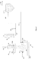
- FIG. 2 illustrates an embodiment in greater detail.
- a gasification reactor system is depicted that produces a raw syngas through a two-stage gasification process.
- the reactor is typically adapted for operation at pressures greater than about 0.69 MPa (100 psig) and temperatures greater than about 1093°C (2000°F), although the pressure may be as high as 8.30 MPa (1200 psig) and the operating temperature up to about 1649°C (3000°F).
- the reactor lower section comprises at least two devices capable of introducing a particulate carbonaceous feedstock and oxygen containing gas or steam. Such devices may be, for example, dispersion devices as are familiar to those having skill in the art.
- the gasification reactor is adapted for conveying the mixture products from the lower reactor section 30 to the upper reactor section 40, and also adapted for introducing a second feed of particulate carbonaceous feedstock in a liquid carrier via one or more inlets (80 and/or 80a).
- inlets may be a dispersion device such as used in the reactor lower section, or a simple feeding tube.
- the second feed contacts and mixes with the mixture products rising from the first reaction zone 30 to produce a second product stream comprising syngas, char, ash and volatile tars.
- the reactor upper section additionally comprises an outlet and conduit 120 for conveying the second product stream out of the upper reactor section 40 and to a residence vessel 90.
- the residence vessel 90 is adapted for accepting the product stream 120 from the reactor upper section 40 and providing sufficient residence time at a temperature exceeding about 816°C (1500°F) for thermal degradation/cracking of un-reacted volatile tars present in the raw gas stream passing therethrough.
- the residence vessel may be replaced by a reactor comprising one or more catalysts capable of catalyzing the destruction of tar, one or more sorbents capable of adsorbing residual tar, or both.
- the syngas leaving the residence vessel 90 comprises negligible levels of tar, and is thus hereinafter termed a "near-zero tar syngas".
- the residence vessel 90 is designed to withstand operating pressures that are similar to those utilized within the gasification reactor 10.
- a conduit 97 conveys the near-zero tar syngas directly from the residence vessel 90 outlet to the particulate filtering device 175.
- a quenching medium such as water
- the inlet 210 may be of any design that allows passage of the quenching medium into a pressurized system.
- the inlet 210 is adapted for introducing a water stream and mixing the water stream with the reduced particulate syngas conveyed through the conduit 97.
- Spray nozzles and dispersion devices are commercially available that can perform such function and can be implemented by one having skill in the art.
- the quenching medium contacts the near-zero-tar syngas after it has exited the residence vessel 90 and is being conveyed via conduit 97 to the particulate filtering device 175.
- the direct contact between the quenching medium and the near-zero-tar syngas takes advantage of the latent heat of vaporization of the quenching medium by flashing the quenching medium to vapor, thereby producing a cooled, moisturized syngas that has a temperature in a range of between about 288°C (550°F) and about 649°C (1200°F).
- the temperature of the cooled moisturized syngas is between about 316°C (600°F) and about 593°C (1100°F).
- the temperature of the cooled moisturized syngas is between about 232°C (450°F) and about 538°C (1000°F). In certain embodiments, the temperature of the cooled moisturized syngas is between about 288°C (550°F) and about 510°C (950°F). In certain embodiments, the temperature of the cooled moisturized syngas is between about 316°C (600°F) and about 510°C (950°F).
- the gasification process within the two-stage gasification system begins within the first reaction zone (or reactor lower-section 30), when a particulate carbonaceous feedstock 60 and/or 60a is mixed with a gas stream comprising an oxygen-containing gas 100 and/or steam and a rapid exothermic reaction takes place in which a first portion of particulate solid carbonaceous feedstock is converted into a first mixture product comprising steam, hydrogen, carbon monoxide, carbon dioxide, methane, and entrained particulates such as ash (see Table 1). Ash is comprised of the non-combustible mineral content of the carbonaceous feedstock.
- the temperature of the reactor lower section 30 is maintained higher than the ash melting point, which allows the ash to melt and agglomerate to form a viscous liquid known as slag.
- the slag falls to the bottom of the first reaction zone, flows through a tap hole 20 and into a slag quench chamber (not depicted), whereupon it is water-quenched and directed via an outlet for slag processing and final disposal 115.
- Exothermic combustion reactions occurring in the reactor lower section 30 raise the temperature to between 1093°C (2000°F) and 1649°C (3000°F). This heat is carried upward to the second reaction zone 40 (or reactor upper section) and provides heat for the endothermic devolatilization and pyrolysis, or optionally, the drying of a second portion of particulate solid carbonaceous feedstock in a liquid carrier that is introduced into the second reaction zone 40 via inlets 80 and/or 80a.
- the physical conditions in the second reaction zone 40 are controlled to assure rapid heating of the carbonaceous feedstock.
- the carbonaceous feedstock enters the reactor upper-section 40, it comes into contact with the hot first product stream rising from the first reaction zone (not depicted).
- the feedstock is dried as the liquid carrier vaporizes, and a portion of the feedstock is gasified via endothermic reactions such as the carbon steam reaction ( C + H 2 O ⁇ CO + H 2 ) to produce a second product stream comprising syngas and solids comprising ash, and devolatilized carbon (char).
- the second product stream may additionally comprise dried, unreacted feedstock.
- the second product stream exiting the reactor upper section 40 of the gasification reactor 10 via conduit 120 predominantly comprises carbon monoxide (CO), carbon dioxide (CO 2 ), hydrogen (H 2 ), water (H 2 O), methane (CH 4 ), ash, char, and nitrogen (N 2 ).
- Table 1 depicts the typical composition of the raw synthesis gas stream produced by a conventional two-stage slurry-fed gasifier of the E-GasTM configuration (owned by Lummus Technology Inc.).
- the second product stream typically comprises one or more undesirable components (i.e., contaminants) such as, for example volatile tars created by the endothermic reactions occurring in the second stage/second reaction zone.
- a benefit of processes and systems disclosed herein is that the water stream utilized as quenching medium can be of lower quality than the boiler feed water that otherwise would be necessary to produce high-pressure steam in a HTHRU for injection into, or immediately upstream from, the water-gas shift reactor.
- High purity water must be fed to a HTHRU to prevent fouling of the heat transfer surfaces. Eliminating the need for a HTHRU increases overall efficiency of the process and system by reducing the amount of high-purity boiler feed water required, thereby eliminating or reducing the size of water treatment equipment that would otherwise be needed.
- the cooled, moisturized syngas is conveyed through conduit 97 a particulate filtering device 175 to remove residual solids, fines and particulates from the syngas passing therethrough, thereby producing a particulate-free syngas 200.
- Filtration may be achieved through any conventional filtration means, such as, for example, a cyclone, bag filter or candle filter. The use and construction of these devices is conventional, and a more detailed discussion is outside the scope of the current disclosure.
- Conveying the cooled, moisturized syngas through the particulate filtering device 175 is performed at a temperature that is greater than the condensation temperature of one or more components present in the cooled syngas and prevents the condensation of the one or more components that are selected from the group consisting of: water, ash constituents, and residual volatile tars.
- the systems and processes disclosed herein may optionally be utilized to prevent condensation of ash constituents that remain in gaseous phase at temperatures above 427°C (800°F). At slightly higher temperatures (above about 538°C (1000 °F)) the inventive systems and methods may prevent the condensation of any residual volatile tars and the subsequent deposition of these tars onto the surfaces of the particulate filtering device as the cooled, moisturized syngas is filtered through them.
- the temperature of the cooled, moisturized syngas is about 427°C (800°F) or less, such that conventional filtration elements constructed from steel alloys can be utilized in the particulate filtering device.
- the temperature of the cooled, moisturized syngas is always controlled such that it remains above the condensation temperature (or dew point) of steam present in the syngas, as this would blind and/or corrode any particulate filtering device that operates by dry filtration.
- the particulate filtration device 175 may comprise filtration elements constructed from more heat resistant materials that may include, for example, porous ceramics or any other heat-resistant materials known to those having skill in the art.
- any residual solids, fines and particulates that are captured by the particulate filtering device 175 are returned to the reactor lower section via a conduit 215 to increase the overall efficiency of the process.
- the particulate-free syngas 200 exiting the particulate filtering device may be optionally conveyed to a conventional chloride scrubber (not depicted) to remove chlorides and other impurities.
- the particulate free syngas 200 is conveyed to at least one shift reactor (not depicted) that facilitates the water-gas shift reaction: CO + H 2 O ⁇ CO 2 + H 2 , thereby producing a shifted syngas.
- shift reactor not depicted
- each shift reactor comprises a catalyst and is configured to operate at a temperature in a range of about 204°C (400°F) to 482°C (900°F), to react carbon monoxide and steam present in the particulate-free syngas passing through the reactor to produce a shifted syngas with an increased level of hydrogen gas and a decreased level of carbon monoxide.
- multiple shift reactors may be utilized, with one maintained at a higher temperature.
- Many conventional catalysts can be utilized to facilitate this water-gas shift reaction, including, but not limited to magnetite, Raney copper, as well as other transition metals and transition metal oxides.
- sulfur resistant conventional hydrotreating catalysts may be utilized, such as, for example those comprising Nickel and molybdenum (NiMo) as well as cobalt and molybdenum (CoMo).
- the catalyst is resistant to deactivation by sulfur contaminants present in the particulate free syngas.
- Such catalysts are conventional and one having skill in the art can implement them in the manner described herein.
- the resulting shifted syngas can then be utilized in various ways, such as fuel for a gas turbine as part of an Integrated Gasification Combined Cycle (IGCC) power plant, or as feedstock for chemical manufacturing process or a synthetic natural gas (SNG) production process. Such processes are conventional and outside of the scope of this disclosure. Certain embodiments may additionally comprise recovering carbon dioxide from the shifted syngas, wherein the apparatus utilized for recovery is located downstream from the shift reactor.
- IGCC Integrated Gasification Combined Cycle
- SNG synthetic natural gas
- the quenching medium introduced via at least one inlet 210 creates steam in situ, thereby significantly reducing the amount of steam that must be added to condition the particulate-free syngas prior to conducting a water-gas shift reaction.
- the particulate-free syngas may be water scrubbed for removal of chlorides, further cooled, de-moisturized and desulfurized.
- the process water utilized to quench the raw syngas can be mostly condensed out in a Low Temperature Heat Recovery Unit (LTHRU) as sour water. Water of boiler feed quality is then required to remoisturize the desulfurized syngas before it is used as fuel for gas turbines.
- LTHRU Low Temperature Heat Recovery Unit
- the test case was a two-stage gasifier (as described herein) with a capacity of 6,108 tons (6,733 short tons) per day of petroleum coke as feedstock.
- the results of the modeling indicated that overall gasifier performance does not appreciably change, and the raw syngas produced from the gasifier is of very similar composition to that shown in Table 1. In fact, most components differed by less than 1% on a mole basis.
- syngas is synonymous with synthesis gas or synthetic gas
- gas is synonymous with methane, natural gas, as well as gasoline or any other liquid hydrocarbon fuel.
Landscapes
- Chemical & Material Sciences (AREA)
- Engineering & Computer Science (AREA)
- Combustion & Propulsion (AREA)
- Oil, Petroleum & Natural Gas (AREA)
- Organic Chemistry (AREA)
- General Chemical & Material Sciences (AREA)
- Chemical Kinetics & Catalysis (AREA)
- Physics & Mathematics (AREA)
- Thermal Sciences (AREA)
- Industrial Gases (AREA)
- Organic Low-Molecular-Weight Compounds And Preparation Thereof (AREA)
- Hydrogen, Water And Hydrids (AREA)
- Processing Of Solid Wastes (AREA)
- Acyclic And Carbocyclic Compounds In Medicinal Compositions (AREA)
Claims (18)
- Procédé de gazéification non catalytique à deux stades, comprenant :(a) l'introduction d'une charge d'alimentation carbonée particulaire (60, 60a) dans une section inférieure de réacteur (30) d'un réacteur de gazéification à deux stades (10) et la combustion partielle dans celui-ci avec un flux de gaz comprenant un apport en oxygène (100) choisi dans un groupe constitué par un gaz contenant de l'oxygène, de la vapeur et des mélanges de ceux-ci, en faisant ainsi évoluer la chaleur et en formant un premier flux de produit comprenant du gaz de synthèse et du laitier fondu ;(b) le passage du gaz de synthèse de l'étape (a) dans une section supérieure (40) de réacteur du réacteur de gazéification à deux stades (10) et la mise en contact dans celui-ci avec un flux comprenant une boue de charge d'alimentation carbonée particulaire dans un support liquide, formant ainsi un second flux de produit (120) comprenant du gaz de synthèse et des solides comprenant des cendres et du résidu de carbonisation ;(c) le passage du second flux de produit (120) dans un réacteur (90) qui est maintenu à une température supérieure à environ 816°C (1500°F), dans lequel le gaz de synthèse réside dans le réacteur (90) pendant un temps suffisant pour dégrader thermiquement les goudrons volatils présents dans le gaz de synthèse, produisant ainsi un produit comprenant un gaz de synthèse à teneur en goudrons proche de zéro ;d) le transport du gaz de synthèse à teneur en goudrons proche de zéro directement du réacteur (90) vers un dispositif de filtrage de particules (175) à travers un conduit (97),e) l'introduction d'un flux d'eau par au moins une entrée (210) située sur le conduit (97) et la mise en contact avec le gaz de synthèse à teneur en goudrons proche de zéro, produisant ainsi de la vapeur et un gaz de synthèse humidifié refroidi, dans lequel la température du gaz de synthèse humidifié refroidi reste supérieure au point de condensation de la vapeur, mais inférieure à environ 649°C (1200°F) ; etf) l'élimination des solides, des fines et des particules résiduels du gaz de synthèse humidifié refroidi en dirigeant le gaz de synthèse refroidi à travers le dispositif de filtrage de particules (175), produisant ainsi un gaz de synthèse exempt de particules (200).
- Procédé selon la revendication 1, comprenant en outre l'acheminement du gaz de synthèse à faible teneur en particules vers un réacteur de conversion contenant au moins un catalyseur et la mise en réaction d'au moins une partie du monoxyde de carbone présent dans le gaz de synthèse exempt de particules (200) de l'étape (f) avec la vapeur produite à l'étape (e) et de la vapeur supplémentaire produite par injection d'eau dans ou immédiatement en amont du réacteur de conversion, produisant ainsi un gaz de synthèse converti comprenant du dioxyde de carbone et de l'hydrogène supplémentaires.
- Procédé selon la revendication 1, dans lequel la température du gaz de synthèse humidifié refroidi est suffisante pour empêcher la condensation d'un ou plusieurs composants du gaz de synthèse humidifié refroidi, dans lequel la condensation du ou des composants entraîne leur dépôt sur le dispositif de filtrage de particules (175) de l'étape (f).
- Procédé selon la revendication 3, dans lequel un ou plusieurs composants sont choisis dans le groupe constitué par : l'eau, des constituants de cendres, et des goudrons volatils résiduels.
- Procédé selon la revendication 1, dans lequel le flux d'eau de l'étape (e) est de qualité inférieure à l'eau d'alimentation de chaudière.
- Procédé selon la revendication 1, dans lequel les solides, les fines et les particules résiduels de l'étape (f) sont renvoyés dans la section inférieure de réacteur (30).
- Procédé selon la revendication 1, dans lequel la température du gaz de synthèse humidifié refroidi de l'étape (f) est comprise entre environ 288°C (550°F) et environ 649°C (1200°F).
- Procédé selon la revendication 1, dans lequel la température du gaz de synthèse humidifié refroidi de l'étape (f) est comprise entre environ 316°C (600°F) et environ 593°C (1100°F).
- Procédé selon la revendication 1, dans lequel la température du gaz de synthèse humidifié refroidi de l'étape (f) est comprise entre environ 232°C (450°F) et environ 538°C (1000°F).
- Procédé selon la revendication 1, dans lequel la température du gaz de synthèse humidifié refroidi de l'étape (f) est comprise entre environ 288°C (550°F) et environ 510°C (950°F).
- Procédé selon la revendication 1, dans lequel la température du gaz de synthèse humidifié refroidi de l'étape (f) est comprise entre environ 316°C (600°F) et environ 510°C (950°F).
- Procédé selon la revendication 1, comprenant en outre la récupération du dioxyde de carbone du gaz de synthèse exempt de particules (200).
- Procédé selon la revendication 2, dans lequel au moins une partie du gaz de synthèse converti est utilisée comme charge d'alimentation pour un procédé de fabrication de produits chimiques ou de carburants.
- Procédé selon la revendication 2, comprenant en outre la récupération du dioxyde de carbone du gaz de synthèse converti.
- Système de gazéification à deux stades d'une charge d'alimentation carbonée particulaire, comprenant :(a) un réacteur de gazéification (10) comprenant une section supérieure de réacteur (40) et une section inférieure de réacteur (30) adaptées pour fonctionner à des pressions supérieures à environ 0,69 MPa (100 psig) et des températures supérieures à environ 1093°C (2000°F), dans lequel la section inférieure de réacteur (30) est adaptée pour introduire la charge d'alimentation carbonée particulaire (60, 60a) et un gaz contenant de l'oxygène (100) ou de la vapeur et pour y brûler partiellement afin de former des produits de mélange, dans lequel le réacteur de gazéification (10) est adapté pour transporter les produits de mélange de la section inférieure de réacteur (30) à la section supérieure de réacteur (40) ; dans lequel ladite section supérieure de réacteur (40) est adaptée pour introduire une charge d'alimentation carbonée particulaire supplémentaire dans un support liquide et pour la combiner avec les produits de mélange pour produire de manière endothermique un flux de produits (120) comprenant du gaz de synthèse, du résidu de carbonisation, des cendres et des goudrons volatils ;(b) une cuve de séjour (90) située en aval du réacteur de gazéification (10), dans lequel la cuve de séjour (90) est adaptée pour accepter le flux de produit (120) et fonctionner à une pression supérieure à environ 0,69 MPa (100 psig) et une température supérieure à environ 816°C (1500°F), dans lequel la cuve de séjour (90) est adaptée pour fournir un temps de séjour suffisant pour que le flux de produit (120) transporté à travers celle-ci permette la dégradation thermique d'une majeure partie des goudrons volatils présents dans le gaz de synthèse à particules réduites et produire ainsi un gaz de synthèse à teneur en goudrons proche de zéro ;(c) un conduit (97) comprenant au moins une entrée (210) située immédiatement en aval de la cuve de séjour (90) et raccordée à la cuve de séjour (90), dans lequel l'au moins une entrée (120) est adaptée pour introduire un flux d'eau et mélanger le flux d'eau avec le gaz de synthèse à particules réduites qui est transporté à travers celui-ci ;d) un dispositif de filtrage de particules (175) situé immédiatement en aval du conduit (97) et raccordé au conduit (97), dans lequel le dispositif de filtrage de particules (175) est adapté pour recevoir un gaz de synthèse humidifié refroidi dans une plage d'environ 288°C (550°F) à environ 649°C (1200°F), et pour éliminer les solides, les fines et les particules résiduels du gaz de synthèse humidifié refroidi passant à travers celui-ci, produisant ainsi un gaz de synthèse (200) exempt de particules.
- Système selon la revendication 15, comprenant en outre un réacteur de conversion situé en aval du dispositif de filtrage de particules (175) et raccordé au dispositif de filtrage de particules (175), dans lequel le réacteur de conversion comprend un catalyseur et est adapté pour fonctionner à une température dans une plage d'environ 204°C (400°F) à 482°C (900°F), dans lequel le réacteur de conversion est adapté pour faire réagir le monoxyde de carbone et la vapeur présents dans le gaz de synthèse exempt de particules (200) passant à travers celui-ci, produisant ainsi un gaz de synthèse converti.
- Système selon la revendication 16, comprenant en outre un appareil pour récupérer le dioxyde de carbone du gaz de synthèse converti exempt de particules, dans lequel l'appareil est situé en aval du réacteur de conversion.
- Système selon la revendication 15, dans lequel le dispositif de filtrage de particules (175) de la partie (d) est un filtre à bougie comprenant des éléments adaptés pour fonctionner à une température allant jusqu'à environ 649°C (1200°F).
Applications Claiming Priority (2)
| Application Number | Priority Date | Filing Date | Title |
|---|---|---|---|
| US201261664415P | 2012-06-26 | 2012-06-26 | |
| PCT/US2013/047851 WO2014004646A1 (fr) | 2012-06-26 | 2013-06-26 | Gazéification à deux étages avec double refroidissement |
Publications (3)
| Publication Number | Publication Date |
|---|---|
| EP2875103A1 EP2875103A1 (fr) | 2015-05-27 |
| EP2875103A4 EP2875103A4 (fr) | 2016-05-11 |
| EP2875103B1 true EP2875103B1 (fr) | 2020-04-29 |
Family
ID=49783826
Family Applications (1)
| Application Number | Title | Priority Date | Filing Date |
|---|---|---|---|
| EP13810468.2A Active EP2875103B1 (fr) | 2012-06-26 | 2013-06-26 | Gazéification à deux étages avec double refroidissement |
Country Status (20)
| Country | Link |
|---|---|
| US (1) | US9567538B2 (fr) |
| EP (1) | EP2875103B1 (fr) |
| JP (2) | JP2015525810A (fr) |
| KR (1) | KR101644760B1 (fr) |
| CN (1) | CN104428401B (fr) |
| BR (1) | BR112014032652B1 (fr) |
| CA (1) | CA2877691C (fr) |
| CL (1) | CL2014003528A1 (fr) |
| CO (1) | CO7240436A2 (fr) |
| EA (1) | EA029814B1 (fr) |
| ES (1) | ES2804520T3 (fr) |
| IN (1) | IN2014MN02547A (fr) |
| MX (1) | MX372666B (fr) |
| MY (1) | MY167593A (fr) |
| PH (1) | PH12015500011B1 (fr) |
| PT (1) | PT2875103T (fr) |
| SG (1) | SG11201408665XA (fr) |
| UA (1) | UA112362C2 (fr) |
| WO (1) | WO2014004646A1 (fr) |
| ZA (1) | ZA201409449B (fr) |
Families Citing this family (14)
| Publication number | Priority date | Publication date | Assignee | Title |
|---|---|---|---|---|
| JP6025603B2 (ja) * | 2013-02-21 | 2016-11-16 | 三菱重工業株式会社 | Coシフト反応装置及びcoシフト変換方法 |
| US20160122669A1 (en) * | 2014-11-05 | 2016-05-05 | General Electric Company | System and method for gasification |
| NL2014786B1 (en) * | 2015-05-11 | 2017-01-26 | Dahlman Renewable Tech B V | Method and systems for treating synthesis gas. |
| KR102932021B1 (ko) | 2015-11-12 | 2026-02-27 | 바이오스테이지, 인크. | 문합 또는 다른 생리학적 위치에서 위장 조직을 생성하기 위한 시스템 및 방법 |
| EP3423550B1 (fr) * | 2016-03-04 | 2021-04-21 | Lummus Technology LLC | Gazéifieur à deux étages et procédé de gazéification présentant une flexibilité de la charge de départ |
| US11643609B2 (en) * | 2016-08-04 | 2023-05-09 | Reliance Industries Limited | Process and a system for producing synthesis gas |
| NL2019552B1 (en) * | 2017-09-14 | 2019-03-27 | Torrgas Tech B V | Process to prepare a char product and a syngas mixture |
| EP3927764A1 (fr) * | 2019-02-21 | 2021-12-29 | Teknologian Tutkimuskeskus VTT OY | Procédé et agencement de traitement pour la production d'hydrocarbures et leur utilisation |
| CN114479942A (zh) * | 2020-10-26 | 2022-05-13 | 中国石化工程建设有限公司 | 一种制备煤气化合成气的方法和系统 |
| ES2965008T3 (es) * | 2021-01-06 | 2024-04-10 | Gidara Energy B V | Proceso para producir gas de síntesis a través de conversión termoquímica de biomasa y materiales residuales |
| CN113234493A (zh) * | 2021-06-10 | 2021-08-10 | 哈尔滨理工大学 | 一种改善煤气化后wgsr气体组成的固液气分离系统 |
| EP4619491A1 (fr) * | 2022-11-16 | 2025-09-24 | Sungas Renewables, Inc. | Flexibilité de traitement accrue dans la gazéification |
| EP4646468A2 (fr) * | 2023-01-05 | 2025-11-12 | Sungas Renewables, Inc. | Opérations d'épuration intégrées pour le traitement de gaz de synthèse à partir de la gazéification |
| WO2025038697A2 (fr) * | 2023-08-14 | 2025-02-20 | Sungas Renewables, Inc. | Intégration de gazéification et synthèse de méthanol |
Family Cites Families (19)
| Publication number | Priority date | Publication date | Assignee | Title |
|---|---|---|---|---|
| US4069024A (en) | 1977-05-09 | 1978-01-17 | Combustion Engineering, Inc. | Two-stage gasification system |
| US4872886A (en) | 1985-11-29 | 1989-10-10 | The Dow Chemical Company | Two-stage coal gasification process |
| US5415673A (en) | 1993-10-15 | 1995-05-16 | Texaco Inc. | Energy efficient filtration of syngas cooling and scrubbing water |
| US6141796A (en) | 1996-08-01 | 2000-11-07 | Isentropic Systems Ltd. | Use of carbonaceous fuels |
| EP1877522B1 (fr) * | 2005-05-02 | 2018-02-28 | Shell Internationale Research Maatschappij B.V. | Procede de quench de gaz de synthèse |
| US20070225382A1 (en) * | 2005-10-14 | 2007-09-27 | Van Den Berg Robert E | Method for producing synthesis gas or a hydrocarbon product |
| WO2007125047A1 (fr) * | 2006-05-01 | 2007-11-08 | Shell Internationale Research Maatschappij B.V. | Réacteur de gazéification et son utilisation |
| US8211191B2 (en) | 2007-08-07 | 2012-07-03 | Phillips 66 Company | Upright gasifier |
| US8460410B2 (en) | 2008-08-15 | 2013-06-11 | Phillips 66 Company | Two stage entrained gasification system and process |
| US20100132257A1 (en) * | 2008-12-01 | 2010-06-03 | Kellogg Brown & Root Llc | Systems and Methods for Increasing Carbon Dioxide in Gasification |
| TWI558807B (zh) * | 2008-12-17 | 2016-11-21 | 祿幕斯科技公司 | 包含分段漿料添加之氣化系統及方法 |
| TW201026395A (en) | 2008-12-24 | 2010-07-16 | Conocophillips Co | Tar-free gasification system and process |
| US9074149B2 (en) | 2009-01-21 | 2015-07-07 | Lummus Technology Inc. | Methods and systems for treating a gasification slag product |
| US8357216B2 (en) * | 2009-04-01 | 2013-01-22 | Phillips 66 Company | Two stage dry feed gasification system and process |
| US9611437B2 (en) * | 2010-01-12 | 2017-04-04 | Lummus Technology Inc. | Producing low methane syngas from a two-stage gasifier |
| US8268023B2 (en) * | 2010-04-26 | 2012-09-18 | General Electric Company | Water gas shift reactor system for integrated gasification combined cycle power generation systems |
| CN101906324B (zh) * | 2010-07-20 | 2013-04-03 | 武汉凯迪控股投资有限公司 | 生物质水蒸汽间接气化工艺及其设备 |
| CN102226107A (zh) * | 2011-05-26 | 2011-10-26 | 中国林业科学研究院林产化学工业研究所 | 二段式生物质高温气化制备合成气工艺及设备 |
| US8951313B2 (en) * | 2012-03-28 | 2015-02-10 | General Electric Company | Gasifier cooling system with convective syngas cooler and quench chamber |
-
2013
- 2013-06-26 MY MYPI2014003580A patent/MY167593A/en unknown
- 2013-06-26 JP JP2015520430A patent/JP2015525810A/ja active Pending
- 2013-06-26 IN IN2547MUN2014 patent/IN2014MN02547A/en unknown
- 2013-06-26 PT PT138104682T patent/PT2875103T/pt unknown
- 2013-06-26 UA UAA201500407A patent/UA112362C2/uk unknown
- 2013-06-26 ES ES13810468T patent/ES2804520T3/es active Active
- 2013-06-26 US US14/411,015 patent/US9567538B2/en active Active
- 2013-06-26 KR KR1020157001909A patent/KR101644760B1/ko active Active
- 2013-06-26 MX MX2014015735A patent/MX372666B/es active IP Right Grant
- 2013-06-26 EA EA201590090A patent/EA029814B1/ru unknown
- 2013-06-26 WO PCT/US2013/047851 patent/WO2014004646A1/fr not_active Ceased
- 2013-06-26 BR BR112014032652-5A patent/BR112014032652B1/pt active IP Right Grant
- 2013-06-26 CN CN201380033902.9A patent/CN104428401B/zh active Active
- 2013-06-26 EP EP13810468.2A patent/EP2875103B1/fr active Active
- 2013-06-26 SG SG11201408665XA patent/SG11201408665XA/en unknown
- 2013-06-26 CA CA2877691A patent/CA2877691C/fr active Active
-
2014
- 2014-12-19 ZA ZA2014/09449A patent/ZA201409449B/en unknown
- 2014-12-24 CL CL2014003528A patent/CL2014003528A1/es unknown
- 2014-12-26 CO CO14284179A patent/CO7240436A2/es unknown
-
2015
- 2015-01-05 PH PH12015500011A patent/PH12015500011B1/en unknown
-
2016
- 2016-08-12 JP JP2016158467A patent/JP6371809B2/ja active Active
Non-Patent Citations (1)
| Title |
|---|
| None * |
Also Published As
| Publication number | Publication date |
|---|---|
| US20150299590A1 (en) | 2015-10-22 |
| EP2875103A4 (fr) | 2016-05-11 |
| ES2804520T3 (es) | 2021-02-08 |
| CL2014003528A1 (es) | 2015-07-03 |
| CO7240436A2 (es) | 2015-04-17 |
| UA112362C2 (uk) | 2016-08-25 |
| IN2014MN02547A (fr) | 2015-07-24 |
| PH12015500011B1 (en) | 2017-10-25 |
| CN104428401A (zh) | 2015-03-18 |
| SG11201408665XA (en) | 2015-01-29 |
| KR20150023873A (ko) | 2015-03-05 |
| EA029814B1 (ru) | 2018-05-31 |
| ZA201409449B (en) | 2015-12-23 |
| PH12015500011A1 (en) | 2015-04-06 |
| CN104428401B (zh) | 2017-03-08 |
| US9567538B2 (en) | 2017-02-14 |
| BR112014032652B1 (pt) | 2021-07-20 |
| BR112014032652A2 (pt) | 2021-04-20 |
| CA2877691C (fr) | 2018-06-12 |
| MY167593A (en) | 2018-09-20 |
| JP6371809B2 (ja) | 2018-08-08 |
| WO2014004646A1 (fr) | 2014-01-03 |
| KR101644760B1 (ko) | 2016-08-01 |
| JP2015525810A (ja) | 2015-09-07 |
| JP2017020038A (ja) | 2017-01-26 |
| EP2875103A1 (fr) | 2015-05-27 |
| PT2875103T (pt) | 2020-06-23 |
| MX372666B (es) | 2020-05-14 |
| CA2877691A1 (fr) | 2014-01-03 |
| EA201590090A1 (ru) | 2015-04-30 |
| MX2014015735A (es) | 2015-06-05 |
Similar Documents
| Publication | Publication Date | Title |
|---|---|---|
| EP2875103B1 (fr) | Gazéification à deux étages avec double refroidissement | |
| US8460410B2 (en) | Two stage entrained gasification system and process | |
| US8888875B2 (en) | Methods for feedstock pretreatment and transport to gasification | |
| EP2523897B1 (fr) | Production de gaz de synthèse à faible teneur en méthane à partir d'un appareil de gazéification à deux étages | |
| Gray | Major gasifiers for IGCC systems | |
| Higman | Gasification process technology | |
| EP2830992B1 (fr) | Procédé intégré pour la gazéification de pétrole brut total dans un gazéifieur à membrane et génération d'électricité | |
| JP5851116B2 (ja) | 石炭ガス化システム |
Legal Events
| Date | Code | Title | Description |
|---|---|---|---|
| PUAI | Public reference made under article 153(3) epc to a published international application that has entered the european phase |
Free format text: ORIGINAL CODE: 0009012 |
|
| 17P | Request for examination filed |
Effective date: 20141231 |
|
| AK | Designated contracting states |
Kind code of ref document: A1 Designated state(s): AL AT BE BG CH CY CZ DE DK EE ES FI FR GB GR HR HU IE IS IT LI LT LU LV MC MK MT NL NO PL PT RO RS SE SI SK SM TR |
|
| AX | Request for extension of the european patent |
Extension state: BA ME |
|
| DAX | Request for extension of the european patent (deleted) | ||
| RA4 | Supplementary search report drawn up and despatched (corrected) |
Effective date: 20160408 |
|
| RIC1 | Information provided on ipc code assigned before grant |
Ipc: C10J 3/46 20060101AFI20160404BHEP Ipc: C10K 1/28 20060101ALI20160404BHEP Ipc: C10J 3/84 20060101ALI20160404BHEP |
|
| STAA | Information on the status of an ep patent application or granted ep patent |
Free format text: STATUS: EXAMINATION IS IN PROGRESS |
|
| 17Q | First examination report despatched |
Effective date: 20180213 |
|
| GRAP | Despatch of communication of intention to grant a patent |
Free format text: ORIGINAL CODE: EPIDOSNIGR1 |
|
| STAA | Information on the status of an ep patent application or granted ep patent |
Free format text: STATUS: GRANT OF PATENT IS INTENDED |
|
| INTG | Intention to grant announced |
Effective date: 20191111 |
|
| GRAS | Grant fee paid |
Free format text: ORIGINAL CODE: EPIDOSNIGR3 |
|
| GRAA | (expected) grant |
Free format text: ORIGINAL CODE: 0009210 |
|
| STAA | Information on the status of an ep patent application or granted ep patent |
Free format text: STATUS: THE PATENT HAS BEEN GRANTED |
|
| AK | Designated contracting states |
Kind code of ref document: B1 Designated state(s): AL AT BE BG CH CY CZ DE DK EE ES FI FR GB GR HR HU IE IS IT LI LT LU LV MC MK MT NL NO PL PT RO RS SE SI SK SM TR |
|
| REG | Reference to a national code |
Ref country code: GB Ref legal event code: FG4D |
|
| REG | Reference to a national code |
Ref country code: CH Ref legal event code: EP |
|
| REG | Reference to a national code |
Ref country code: DE Ref legal event code: R096 Ref document number: 602013068514 Country of ref document: DE |
|
| REG | Reference to a national code |
Ref country code: AT Ref legal event code: REF Ref document number: 1263289 Country of ref document: AT Kind code of ref document: T Effective date: 20200515 |
|
| REG | Reference to a national code |
Ref country code: IE Ref legal event code: FG4D |
|
| REG | Reference to a national code |
Ref country code: PT Ref legal event code: SC4A Ref document number: 2875103 Country of ref document: PT Date of ref document: 20200623 Kind code of ref document: T Free format text: AVAILABILITY OF NATIONAL TRANSLATION Effective date: 20200617 |
|
| REG | Reference to a national code |
Ref country code: NL Ref legal event code: MP Effective date: 20200429 |
|
| REG | Reference to a national code |
Ref country code: LT Ref legal event code: MG4D |
|
| PG25 | Lapsed in a contracting state [announced via postgrant information from national office to epo] |
Ref country code: IS Free format text: LAPSE BECAUSE OF FAILURE TO SUBMIT A TRANSLATION OF THE DESCRIPTION OR TO PAY THE FEE WITHIN THE PRESCRIBED TIME-LIMIT Effective date: 20200829 Ref country code: NO Free format text: LAPSE BECAUSE OF FAILURE TO SUBMIT A TRANSLATION OF THE DESCRIPTION OR TO PAY THE FEE WITHIN THE PRESCRIBED TIME-LIMIT Effective date: 20200729 Ref country code: GR Free format text: LAPSE BECAUSE OF FAILURE TO SUBMIT A TRANSLATION OF THE DESCRIPTION OR TO PAY THE FEE WITHIN THE PRESCRIBED TIME-LIMIT Effective date: 20200730 Ref country code: FI Free format text: LAPSE BECAUSE OF FAILURE TO SUBMIT A TRANSLATION OF THE DESCRIPTION OR TO PAY THE FEE WITHIN THE PRESCRIBED TIME-LIMIT Effective date: 20200429 Ref country code: SE Free format text: LAPSE BECAUSE OF FAILURE TO SUBMIT A TRANSLATION OF THE DESCRIPTION OR TO PAY THE FEE WITHIN THE PRESCRIBED TIME-LIMIT Effective date: 20200429 Ref country code: LT Free format text: LAPSE BECAUSE OF FAILURE TO SUBMIT A TRANSLATION OF THE DESCRIPTION OR TO PAY THE FEE WITHIN THE PRESCRIBED TIME-LIMIT Effective date: 20200429 |
|
| REG | Reference to a national code |
Ref country code: AT Ref legal event code: MK05 Ref document number: 1263289 Country of ref document: AT Kind code of ref document: T Effective date: 20200429 |
|
| PG25 | Lapsed in a contracting state [announced via postgrant information from national office to epo] |
Ref country code: BG Free format text: LAPSE BECAUSE OF FAILURE TO SUBMIT A TRANSLATION OF THE DESCRIPTION OR TO PAY THE FEE WITHIN THE PRESCRIBED TIME-LIMIT Effective date: 20200729 Ref country code: RS Free format text: LAPSE BECAUSE OF FAILURE TO SUBMIT A TRANSLATION OF THE DESCRIPTION OR TO PAY THE FEE WITHIN THE PRESCRIBED TIME-LIMIT Effective date: 20200429 Ref country code: LV Free format text: LAPSE BECAUSE OF FAILURE TO SUBMIT A TRANSLATION OF THE DESCRIPTION OR TO PAY THE FEE WITHIN THE PRESCRIBED TIME-LIMIT Effective date: 20200429 Ref country code: HR Free format text: LAPSE BECAUSE OF FAILURE TO SUBMIT A TRANSLATION OF THE DESCRIPTION OR TO PAY THE FEE WITHIN THE PRESCRIBED TIME-LIMIT Effective date: 20200429 |
|
| PG25 | Lapsed in a contracting state [announced via postgrant information from national office to epo] |
Ref country code: NL Free format text: LAPSE BECAUSE OF FAILURE TO SUBMIT A TRANSLATION OF THE DESCRIPTION OR TO PAY THE FEE WITHIN THE PRESCRIBED TIME-LIMIT Effective date: 20200429 Ref country code: AL Free format text: LAPSE BECAUSE OF FAILURE TO SUBMIT A TRANSLATION OF THE DESCRIPTION OR TO PAY THE FEE WITHIN THE PRESCRIBED TIME-LIMIT Effective date: 20200429 |
|
| PG25 | Lapsed in a contracting state [announced via postgrant information from national office to epo] |
Ref country code: AT Free format text: LAPSE BECAUSE OF FAILURE TO SUBMIT A TRANSLATION OF THE DESCRIPTION OR TO PAY THE FEE WITHIN THE PRESCRIBED TIME-LIMIT Effective date: 20200429 Ref country code: MC Free format text: LAPSE BECAUSE OF FAILURE TO SUBMIT A TRANSLATION OF THE DESCRIPTION OR TO PAY THE FEE WITHIN THE PRESCRIBED TIME-LIMIT Effective date: 20200429 Ref country code: SM Free format text: LAPSE BECAUSE OF FAILURE TO SUBMIT A TRANSLATION OF THE DESCRIPTION OR TO PAY THE FEE WITHIN THE PRESCRIBED TIME-LIMIT Effective date: 20200429 Ref country code: EE Free format text: LAPSE BECAUSE OF FAILURE TO SUBMIT A TRANSLATION OF THE DESCRIPTION OR TO PAY THE FEE WITHIN THE PRESCRIBED TIME-LIMIT Effective date: 20200429 Ref country code: DK Free format text: LAPSE BECAUSE OF FAILURE TO SUBMIT A TRANSLATION OF THE DESCRIPTION OR TO PAY THE FEE WITHIN THE PRESCRIBED TIME-LIMIT Effective date: 20200429 Ref country code: RO Free format text: LAPSE BECAUSE OF FAILURE TO SUBMIT A TRANSLATION OF THE DESCRIPTION OR TO PAY THE FEE WITHIN THE PRESCRIBED TIME-LIMIT Effective date: 20200429 Ref country code: IT Free format text: LAPSE BECAUSE OF FAILURE TO SUBMIT A TRANSLATION OF THE DESCRIPTION OR TO PAY THE FEE WITHIN THE PRESCRIBED TIME-LIMIT Effective date: 20200429 |
|
| REG | Reference to a national code |
Ref country code: CH Ref legal event code: PL |
|
| REG | Reference to a national code |
Ref country code: DE Ref legal event code: R097 Ref document number: 602013068514 Country of ref document: DE |
|
| REG | Reference to a national code |
Ref country code: ES Ref legal event code: FG2A Ref document number: 2804520 Country of ref document: ES Kind code of ref document: T3 Effective date: 20210208 |
|
| PG25 | Lapsed in a contracting state [announced via postgrant information from national office to epo] |
Ref country code: SK Free format text: LAPSE BECAUSE OF FAILURE TO SUBMIT A TRANSLATION OF THE DESCRIPTION OR TO PAY THE FEE WITHIN THE PRESCRIBED TIME-LIMIT Effective date: 20200429 |
|
| PLBE | No opposition filed within time limit |
Free format text: ORIGINAL CODE: 0009261 |
|
| STAA | Information on the status of an ep patent application or granted ep patent |
Free format text: STATUS: NO OPPOSITION FILED WITHIN TIME LIMIT |
|
| GBPC | Gb: european patent ceased through non-payment of renewal fee |
Effective date: 20200729 |
|
| PG25 | Lapsed in a contracting state [announced via postgrant information from national office to epo] |
Ref country code: LU Free format text: LAPSE BECAUSE OF NON-PAYMENT OF DUE FEES Effective date: 20200626 |
|
| 26N | No opposition filed |
Effective date: 20210201 |
|
| REG | Reference to a national code |
Ref country code: BE Ref legal event code: MM Effective date: 20200630 |
|
| PG25 | Lapsed in a contracting state [announced via postgrant information from national office to epo] |
Ref country code: FR Free format text: LAPSE BECAUSE OF NON-PAYMENT OF DUE FEES Effective date: 20200629 Ref country code: IE Free format text: LAPSE BECAUSE OF NON-PAYMENT OF DUE FEES Effective date: 20200626 Ref country code: GB Free format text: LAPSE BECAUSE OF NON-PAYMENT OF DUE FEES Effective date: 20200729 Ref country code: LI Free format text: LAPSE BECAUSE OF NON-PAYMENT OF DUE FEES Effective date: 20200630 Ref country code: CH Free format text: LAPSE BECAUSE OF NON-PAYMENT OF DUE FEES Effective date: 20200630 |
|
| PG25 | Lapsed in a contracting state [announced via postgrant information from national office to epo] |
Ref country code: BE Free format text: LAPSE BECAUSE OF NON-PAYMENT OF DUE FEES Effective date: 20200630 Ref country code: SI Free format text: LAPSE BECAUSE OF FAILURE TO SUBMIT A TRANSLATION OF THE DESCRIPTION OR TO PAY THE FEE WITHIN THE PRESCRIBED TIME-LIMIT Effective date: 20200429 |
|
| PG25 | Lapsed in a contracting state [announced via postgrant information from national office to epo] |
Ref country code: MT Free format text: LAPSE BECAUSE OF FAILURE TO SUBMIT A TRANSLATION OF THE DESCRIPTION OR TO PAY THE FEE WITHIN THE PRESCRIBED TIME-LIMIT Effective date: 20200429 Ref country code: CY Free format text: LAPSE BECAUSE OF FAILURE TO SUBMIT A TRANSLATION OF THE DESCRIPTION OR TO PAY THE FEE WITHIN THE PRESCRIBED TIME-LIMIT Effective date: 20200429 |
|
| PG25 | Lapsed in a contracting state [announced via postgrant information from national office to epo] |
Ref country code: MK Free format text: LAPSE BECAUSE OF FAILURE TO SUBMIT A TRANSLATION OF THE DESCRIPTION OR TO PAY THE FEE WITHIN THE PRESCRIBED TIME-LIMIT Effective date: 20200429 |
|
| P01 | Opt-out of the competence of the unified patent court (upc) registered |
Effective date: 20230517 |
|
| PGFP | Annual fee paid to national office [announced via postgrant information from national office to epo] |
Ref country code: PL Payment date: 20250414 Year of fee payment: 13 Ref country code: DE Payment date: 20250402 Year of fee payment: 13 |
|
| PGFP | Annual fee paid to national office [announced via postgrant information from national office to epo] |
Ref country code: PT Payment date: 20250620 Year of fee payment: 13 |
|
| PGFP | Annual fee paid to national office [announced via postgrant information from national office to epo] |
Ref country code: TR Payment date: 20250620 Year of fee payment: 13 |
|
| PGFP | Annual fee paid to national office [announced via postgrant information from national office to epo] |
Ref country code: CZ Payment date: 20250618 Year of fee payment: 13 |
|
| PGFP | Annual fee paid to national office [announced via postgrant information from national office to epo] |
Ref country code: ES Payment date: 20250707 Year of fee payment: 13 |