EP2875231B1 - Kraftstoffeinspritzsystem - Google Patents
Kraftstoffeinspritzsystem Download PDFInfo
- Publication number
- EP2875231B1 EP2875231B1 EP13750515.2A EP13750515A EP2875231B1 EP 2875231 B1 EP2875231 B1 EP 2875231B1 EP 13750515 A EP13750515 A EP 13750515A EP 2875231 B1 EP2875231 B1 EP 2875231B1
- Authority
- EP
- European Patent Office
- Prior art keywords
- core
- injection system
- fuel injection
- spacers
- pipe
- Prior art date
- Legal status (The legal status is an assumption and is not a legal conclusion. Google has not performed a legal analysis and makes no representation as to the accuracy of the status listed.)
- Not-in-force
Links
Images


Classifications
-
- F—MECHANICAL ENGINEERING; LIGHTING; HEATING; WEAPONS; BLASTING
- F02—COMBUSTION ENGINES; HOT-GAS OR COMBUSTION-PRODUCT ENGINE PLANTS
- F02M—SUPPLYING COMBUSTION ENGINES IN GENERAL WITH COMBUSTIBLE MIXTURES OR CONSTITUENTS THEREOF
- F02M63/00—Other fuel-injection apparatus having pertinent characteristics not provided for in groups F02M39/00 - F02M57/00 or F02M67/00; Details, component parts, or accessories of fuel-injection apparatus, not provided for in, or of interest apart from, the apparatus of groups F02M39/00 - F02M61/00 or F02M67/00; Combination of fuel pump with other devices, e.g. lubricating oil pump
- F02M63/02—Fuel-injection apparatus having several injectors fed by a common pumping element, or having several pumping elements feeding a common injector; Fuel-injection apparatus having provisions for cutting-out pumps, pumping elements, or injectors; Fuel-injection apparatus having provisions for variably interconnecting pumping elements and injectors alternatively
- F02M63/0225—Fuel-injection apparatus having a common rail feeding several injectors ; Means for varying pressure in common rails; Pumps feeding common rails
- F02M63/0275—Arrangement of common rails
-
- F—MECHANICAL ENGINEERING; LIGHTING; HEATING; WEAPONS; BLASTING
- F02—COMBUSTION ENGINES; HOT-GAS OR COMBUSTION-PRODUCT ENGINE PLANTS
- F02M—SUPPLYING COMBUSTION ENGINES IN GENERAL WITH COMBUSTIBLE MIXTURES OR CONSTITUENTS THEREOF
- F02M55/00—Fuel-injection apparatus characterised by their fuel conduits or their venting means; Arrangements of conduits between fuel tank and pump F02M37/00
- F02M55/04—Means for damping vibrations or pressure fluctuations in injection pump inlets or outlets
-
- F—MECHANICAL ENGINEERING; LIGHTING; HEATING; WEAPONS; BLASTING
- F02—COMBUSTION ENGINES; HOT-GAS OR COMBUSTION-PRODUCT ENGINE PLANTS
- F02M—SUPPLYING COMBUSTION ENGINES IN GENERAL WITH COMBUSTIBLE MIXTURES OR CONSTITUENTS THEREOF
- F02M37/00—Apparatus or systems for feeding liquid fuel from storage containers to carburettors or fuel-injection apparatus; Arrangements for purifying liquid fuel specially adapted for, or arranged on, internal-combustion engines
- F02M37/0011—Constructional details; Manufacturing or assembly of elements of fuel systems; Materials therefor
- F02M37/0041—Means for damping pressure pulsations
-
- F—MECHANICAL ENGINEERING; LIGHTING; HEATING; WEAPONS; BLASTING
- F02—COMBUSTION ENGINES; HOT-GAS OR COMBUSTION-PRODUCT ENGINE PLANTS
- F02M—SUPPLYING COMBUSTION ENGINES IN GENERAL WITH COMBUSTIBLE MIXTURES OR CONSTITUENTS THEREOF
- F02M45/00—Fuel-injection apparatus characterised by having a cyclic delivery of specific time/pressure or time/quantity relationship
- F02M45/02—Fuel-injection apparatus characterised by having a cyclic delivery of specific time/pressure or time/quantity relationship with each cyclic delivery being separated into two or more parts
-
- F—MECHANICAL ENGINEERING; LIGHTING; HEATING; WEAPONS; BLASTING
- F16—ENGINEERING ELEMENTS AND UNITS; GENERAL MEASURES FOR PRODUCING AND MAINTAINING EFFECTIVE FUNCTIONING OF MACHINES OR INSTALLATIONS; THERMAL INSULATION IN GENERAL
- F16L—PIPES; JOINTS OR FITTINGS FOR PIPES; SUPPORTS FOR PIPES, CABLES OR PROTECTIVE TUBING; MEANS FOR THERMAL INSULATION IN GENERAL
- F16L55/00—Devices or appurtenances for use in, or in connection with, pipes or pipe systems
- F16L55/04—Devices damping pulsations or vibrations in fluids
-
- F—MECHANICAL ENGINEERING; LIGHTING; HEATING; WEAPONS; BLASTING
- F02—COMBUSTION ENGINES; HOT-GAS OR COMBUSTION-PRODUCT ENGINE PLANTS
- F02M—SUPPLYING COMBUSTION ENGINES IN GENERAL WITH COMBUSTIBLE MIXTURES OR CONSTITUENTS THEREOF
- F02M2200/00—Details of fuel-injection apparatus, not otherwise provided for
- F02M2200/31—Fuel-injection apparatus having hydraulic pressure fluctuations damping elements
- F02M2200/315—Fuel-injection apparatus having hydraulic pressure fluctuations damping elements for damping fuel pressure fluctuations
Definitions
- the invention relates to a fuel injection system, in particular a common rail injection system, according to the preamble of claim 1.
- a damper device for damping pressure pulsations comprises a sintered metal insert.
- the DE 103 51 089 A1 discloses a method for reducing pressure pulsations in a hydraulic system with hydraulic flow supplied to a pulsation damper.
- the pulsation damper has a plurality of flow channels for dividing the hydraulic flow into a plurality of partial flows.
- the EP 1 741 925 A1 relates to an injector having a multi-bore damper.
- the JP 08261099 A discloses a pulsation damper in which balls with two different diameters are accommodated in a housing.
- a hydraulic pulsation damper in which a filter element made of foamed polyethylene or sintered metal fabric or glass fiber fabric is accommodated in a housing as a damping means.
- a fuel injection system is also known from JP09170514A known.
- the known in the prior art damping devices require a relatively high production cost. So far When porous media are used as damping agents, there is the risk of clogging by dirt particles. In the case of diesel vehicles, especially in winter at low temperatures, the further risk of clogging of the filter medium by precipitating paraffin.
- the object of the present invention is to eliminate the disadvantages of the prior art.
- it is intended to specify a fuel injection system with a damping device which can be produced simply and inexpensively.
- the damping device should ensure trouble-free operation of the fuel injection system.
- the damping device has a tube in which a spacer which is held spaced apart by forming an annular gap is provided.
- the proposed damping device can be easily and inexpensively manufactured using fewer parts.
- the provision of an annular gap renders the damping device immune to clogging by impurities or paraffin contained in the fuel.
- annular gap is understood to mean a passage which extends essentially over the entire axial length of the, preferably cylindrical, core.
- the annular gap has a radial gap width, which substantially over the entire axial Length of the core is essentially constant.
- the annular gap has essentially annular inlet and outlet openings.
- the annular gap can also be interrupted over its circumference, for example by the spacers required to hold the core.
- an axial length l of the core is 0.5 to 50 mm.
- a given by the difference of an inner diameter d of the tube and an outer diameter D of the core gap width ⁇ is suitably 5 microns to 200 microns.
- the outer diameter D of the core is about 0.5 to 50 mm, preferably 2 to 20 mm.
- the value ⁇ is the viscosity of the liquid fuel used in each case, for example the viscosity of diesel fuel or gasoline.
- the predetermined volume flow results in particular from the embodiment of respectively used injectors of the injection pressure and the injection times.
- the pressure loss ⁇ P is desirably set to a value of, for example, 7 bar.
- a suitable relationship between the length 1, the outer diameter D of the core and the gap width ⁇ results directly from this. For example, for a given length l, a suitable gap width ⁇ or vice versa can be calculated.
- the spacers are distributed uniformly over the outer circumference of the core.
- n spacers can each be distributed at an angle of 360 ° / n spaced from each other over the outer periphery of the core.
- the spacers may be separate parts, which are for example rod-shaped or web-like.
- the core can be frictionally held to form an annular gap in the pipe.
- the rod or web-shaped spacers extend over the entire axial length of the core.
- the core is preferably cylindrical. It can be conically tapered at at least one end.
- the core is formed in one piece with the spacers.
- the tube can be formed in one piece with the spacers.
- the core is / are and / or the tube made by extrusion.
- the tube and / or the core are expediently made of metal, preferably of stainless steel.
- the core is shrunk into the tube.
- the process of shrinking can be done easily and inexpensively.
- a damping device for damping pressure pulsations in a fuel injection system can be produced in a particularly simple and cost-effective manner.
- the spacers are formed from pins which are inserted in the core provided holes.
- the holes can be blind holes.
- the pins extend beyond the circumference of the core by a predetermined distance. Their outer surface facing the tube may have a radius which corresponds to the inner radius of the tube, so that the pins in the assembled state bear positively against the inner wall of the tube.
- the bores extend radially with respect to an axis of the core. In an axial plane of the core, at least three, preferably four, pins are advantageously provided uniformly distributed over the circumference, which pins act as spacers.
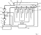
- Fig. 1 schematically shows a fuel injection system according to the invention, namely a common rail injection system.
- fuel F is added.
- a fuel filter 3 is turned on.
- the reference numeral 4 denotes a fuel delivery pump, with which the fuel F of a high pressure pump 6 is supplied via a pressure control valve 5.
- the high pressure pump 6 is connected via a first high pressure line 7 to a manifold 8.
- the manifold 8 is connected in each case via a second high-pressure line 9 to an injector 10.
- four second high-pressure lines 9 are provided, to each of which an injector 10 is connected downstream.
- Reference numeral 11 denotes a control device with which the injectors 10 are controlled in dependence on a plurality of parameters.
- the control unit 10 is u. a. with a pressure limiter 12, a rail pressure sensor 13, a fuel temperature sensor 14 and the pressure control valve 5 for measuring and control purposes.
- By the reference numeral 14 are provided downstream of the manifold 8 provided damping devices.
- the damping devices 14 are here mounted directly on the manifold 8 respectively at an outlet provided for each of the second high-pressure lines 9. At an output of the damping devices 14, the second high-pressure lines 9 are connected. But it may also be that the damping devices 14 in the second high-pressure lines. 9 switched on or attached to an injector-side end of the second high-pressure lines 9.
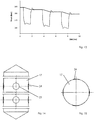
- Fig. 2 shows a plan view of a damping device 14. It comprises a tube 15, in which by means of spacers 16, a core 17 is held. - In particular, in conjunction with Fig. 3 can be seen, the spacers 16 extend over the entire axial length of the cylindrical core 17. They are radially spaced 90 ° from each other.
- the core 17 is expediently shrunk into the tube 15. This ensures a secure and reliable hold of the core 17 in the tube 15.
- the reference numeral 18 denotes a between the spacers 16, the core 17 and the tube 15 remaining annular gap.
- the annular gap 18 may be interrupted in particular by spacers 16. It can also be subdivided by the spacers 16 into annular gap sections, which each form a separate passage for the fuel F flowing through.
- Fig. 4 shows an embodiment of a core 17.
- second spacers 19 are wound around the outer circumference of the core 17, that is formed in the manner of a portion of a helix.
- a swirling flow is formed.
- the design of the second spacers 19, the damping behavior of the damping device 14 can be influenced.
- Fig. 5 shows a further embodiment of a core 17, on the outer circumference third spacers 20 are provided.
- the third spacers 20 do not extend in this case over the entire axial length of the core 17, but only over a relatively small axial portion.
- Fig. 6 shows a further damping device.
- On the inside of the tube 21 fourth spacers 22 are formed.
- Such a tube 21 can be produced for example by means of extrusion.
- a cylindrically shaped core 17 can be fixed quickly and easily by means of shrinking.
- FIGS. 7 and 8 show a plan view of a not included in the claim wording third damping device.
- a cross-section "gear-like" trained core 17 is held in a cylindrical tube 15.
- the core 17 may for example be produced by means of extrusion. He is expediently shrunk into the tube 15.
- the damping device may have a length of 2 to 50 mm, preferably 5 to 20 mm.
- the gap width is suitably 5 to 200 .mu.m, preferably 80 to 120 microns.
- the damping device can be switched on in the region of the distributor tube 8, in particular at the inlet of the distributor tube 8 and / or in the second high-pressure lines 9.
- the damping element is combined with a pressure measuring device.
- the pressure measuring device upstream and downstream of the damping device in each case the pressure can be measured. From the difference of the measured pressures, the instantaneous mass flow can be determined.
- the damping device may have an inlet pipe upstream of the core and a drain pipe downstream of the core.
- a diameter of the inlet and outlet pipes are expediently smaller than a diameter of the tube surrounding the core.
- an inlet and outlet pipe each have a bore, preferably a threaded bore may be provided.
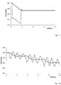
- Fig. 9 shows the pressure curve at the injector and the common rail tube in a fuel injection system, which has no damping device.
- the simulation is based on a calculation, which was carried out with the program "LMS Imagine.Lab AMESim" of the company LMS International NV.
- the simulation was performed using the following constraints: print 200 bar Volume of common rail pipe 60 cm 3 Diameter of the injection line 3 mm Length of injection line 87 mm Diameter of the electronically controllable 2 mm opening Injected volume 0.5 mm 3 Diameter of the nozzle 0.3 mm
- Fig. 10 shows the result of measurements which are in Fig. 9 reproduced simulation confirmed. Again, the injector opens (broken line) in the time window between about 1 ms to 5 ms.
- Fig. 11 shows a simulation of the pressure curves at the injector (broken line) and the common rail tube (solid line), wherein the fuel injection system is provided with a damping device according to the invention.
- the following additional parameters have been used for the simulation: Inner diameter d of the pipe 10.00 mm Outer diameter D of the core 9, 94 mm Length l of the damper 10.00 mm
- the Fig. 12 shows a further simulation of the pressure curves at the injector (broken line) and the common rail tube (solid line), with no damping device is provided.
- the further simulation relates to a multiple injection, wherein the injector is opened three times for a period of about 1.5 ms. How out Fig. 12 it can be seen, thereby occur considerable pressure pulsations on the injector.
- Fig. 13 shows a further simulation according to Fig. 12 , wherein here the fuel injection system is provided with a damping device according to the invention. It can also be observed that virtually no pressure pulsations at the injector (broken line) or on the common rail pipe (solid line) occur more.
- the proposed damping device causes in a fuel injection system, in particular in a common rail injection system, so excellent damping of pressure pulsations. This makes it possible to better control the combustion in an internal combustion engine and thus to reduce unwanted exhaust emissions.
- FIGS. 14 and 15 show a further embodiment of a core 17.
- the core 17 has a cylindrical central part. The two ends of the core 17 are cone-shaped and run to a point.
- the core 17 has radially extending bores 23, in which pins 24 are inserted, which protrude over a predetermined distance from the circumference of the core 17.
- the pins 24 act as spacers.
- the bores 23 are advantageously distributed radially offset by 90 ° over the circumference.
- the in the FIGS. 14 and 15 described core 17 may be similar to those in the Fig. 2 to 7 described cores 17 are fitted or shrunk into a cylindrical tube 15. This results in a simple to manufacture damping device.
Landscapes
- Engineering & Computer Science (AREA)
- General Engineering & Computer Science (AREA)
- Mechanical Engineering (AREA)
- Chemical & Material Sciences (AREA)
- Combustion & Propulsion (AREA)
- Fuel-Injection Apparatus (AREA)
Description
- Die Erfindung betrifft ein Kraftstoffeinspritzsystem, insbesondere ein Common Rail Einspritzsystem, nach dem Oberbegriff des Anspruchs 1.
- Ein solches Kraftstoffeinspritzsystem ist beispielsweise aus der
WO 2004/036029 A1 bekannt. Bei dem bekannten Kraftstoffeinspritzsystem weist eine Dämpfungsvorrichtung zum Dämpfen von Druckpulsationen einen Sintermetalleinsatz auf. - Die
DE 103 51 089 A1 offenbart ein Verfahren zum Verringern von Druckpulsationen in einem Hydrauliksystem mit einem Hydraulikstrom, der einem Pulsationsdämpfer zugeführt wird. Der Pulsationsdämpfer weist eine Mehrzahl von Strömungskanälen zur Unterteilung des Hydraulikstroms in eine Mehrzahl von Teilströmen auf. - Die
EP 1 741 925 A1 betrifft einen Injektor, welcher einen mit mehreren Bohrungen versehenen Dämpfer aufweist. - Die
JP 08261099 A - Aus der
DE 10 2006 016 937 A1 ist ein hydraulischer Pulsationsdämpfer bekannt, bei dem in einem Gehäuse als Dämpfungsmittel ein Filterelement aus geschäumtem Polyethylen oder gesintertem Metallgewebe oder Glasfasergewebe aufgenommen ist. Ein solches Kraftstoffeinspritzsystem ist auch aus derJP09170514A - Aufgabe der vorliegenden Erfindung ist es, die Nachteile nach dem Stand der Technik zu beseitigen. Es soll insbesondere ein Kraftstoffeinspritzsystem mit einer einfach und kostengünstig herstellbaren Dämpfungsvorrichtung angegeben werden. Nach einem weiteren Ziel der Erfindung soll die Dämpfungsvorrichtung einen möglichst störungsfreien Betrieb des Kraftstoffeinspritzsystems gewährleisten.
- Diese Aufgabe wird durch die Merkmale des Anspruchs 1 gelöst. Zweckmäßige Ausgestaltungen der Erfindung ergeben sich aus den Merkmalen der Ansprüche 2 bis 13.
- Nach Maßgabe der Erfindung wird vorgeschlagen, dass die Dämpfungsvorrichtung ein Rohr aufweist, in dem ein über Abstandshalter unter Ausbildung eines Ringspalts beabstandet gehaltener Kern vorgesehen ist. - Die vorgeschlagene Dämpfungsvorrichtung kann unter Verwendung weniger Teile einfach und kostengünstig hergestellt werden. Das Vorsehen eines Ringspalts macht die Dämpfungsvorrichtung unanfällig gegen ein Zusetzen durch im Kraftstoff enthaltene Verunreinigungen oder Paraffin.
- Im Sinne der vorliegenden Erfindung wird unter dem Begriff "Ringspalt" ein sich im Wesentlichen über die gesamte axiale Länge des, vorzugsweise zylindrischen, Kerns erstreckender Durchgang verstanden. Der Ringspalt weist eine radiale Spaltweite auf, welche im Wesentlichen über die gesamte axiale Länge des Kerns im Wesentlichen konstant ist. Der Ringspalt hat im Wesentlichen ringförmige Ein- und Auslassöffnungen. Der Ringspalt kann über seinen Umfang hinweg auch, beispielsweise durch die zum Halten des Kerns erforderlichen Abstandshalter, unterbrochen sein.
- Es hat sich als vorteilhaft erwiesen, dass eine axiale Länge l des Kerns 0,5 bis 50 mm beträgt. Eine durch die Differenz eines Innendurchmessers d des Rohrs und eines Außendurchmessers D des Kerns gegebene Spaltweite δ beträgt zweckmäßigerweise 5 µm bis 200 µm. Ferner hat es sich als zweckmäßig erwiesen, dass der Außendurchmesser D des Kerns etwa 0,5 bis 50 mm, vorzugsweise 2 bis 20 mm, beträgt. Eine derart ausgestaltete Dämpfungsvorrichtung zeichnet sich insbesondere für Common Rail Einspritzsysteme durch eine hervorragende Dämpfung von Druckpulsationen aus.
- Nach einer vorteilhaften Ausgestaltung der Erfindung sind die Länge ℓ und die Spaltweite δ so gewählt, dass ein Druckverlust ΔP zwischen 3 und 12 bar, vorzugsweise zwischen 6 und 9 bar, liegt, wobei gilt:

- µ
- eine vorgegebene Viskosität des Flüssigkeitskraftstoffs,
- v̇
- ein sich einstellender Volumenstrom, und
- D
- der Außendurchmesser des Kerns ist.
- Bei dem Wert µ handelt es sich um die Viskosität des jeweils verwendeten Flüssigkeitskraftstoffs, beispielsweise die Viskosität von Dieselkraftstoff oder Benzin. Der vorgegebene Volumenstrom ergibt sich insbesondere aus der Ausgestaltung der jeweils verwendeten Injektoren des Injektionsdrucks und der Einspritzzeiten. Wie aus der obigen Beziehung ersichtlich ist, wird der Druckverlust ΔP zweckmäßigerweise auf einen Wert von beispielsweise 7 bar festgelegt. Bei gegebener Viskosität des Flüssigkeitskraftstoffs sowie gegebenen Volumenstrom ergibt sich daraus unmittelbar eine geeignete Beziehung zwischen der Länge ℓ, den Außendurchmesser D des Kerns sowie der Spaltbreite δ. Es kann beispielsweise bei vorgegebener Länge ℓ eine geeignete Spaltbreite δ oder umgekehrt berechnet werden. Der vorgenannte Druckverlust ΔP gilt für µ = 10-3 Ns/m2 und v̇ = 0,25 l/min. Für andere Viskositäten µ und/oder Volumenströme v̇ kann nach der obigen Formel ein geeigneter Druckverlust ΔP berechnet werden.
- Nach einer vorteilhaften Ausgestaltung sind die Abstandshalter gleichmäßig über den Außenumfang des Kerns verteilt. Insbesondere können n Abstandshalter jeweils in einem Winkel von 360°/n voneinander beabstandet über den Außenumfang des Kerns verteilt sein.
- Die Abstandshalter können separate Teile sein, welche beispielsweise stab- oder stegartig ausgebildet sind. Damit kann der Kern reibschlüssig unter Ausbildung eines Ringspalts im Rohr gehalten werden. Zweckmäßigerweise erstrecken sich die stab- oder stegförmigen Abstandshalter über die gesamte axiale Länge des Kerns. Der Kern ist vorzugsweise zylindrisch ausgebildet. Er kann an zumindest einem Ende kegelartig zugespitzt sein.
- Nach einer vorteilhaften Ausgestaltung der Erfindung ist der Kern in einem Stück mit den Abstandshaltern ausgebildet. Desgleichen kann auch das Rohr in einem Stück mit den Abstandshaltern ausgebildet sein. Zweckmäßigerweise ist/sind der Kern und/oder das Rohr mittels Strangpressen hergestellt. Das Rohr und/oder der Kern sind zweckmäßigerweise aus Metall, vorzugsweise aus Edelstahl, hergestellt.
- Nach einer besonders vorteilhaften Ausgestaltung der Erfindung ist der Kern in das Rohr eingeschrumpft. Der Vorgang des Einschrumpfens lässt sich einfach und kostengünstig durchführen. Damit kann - im Vergleich zum Stand der Technik - auf besonders einfache und kostengünstige Weise eine Dämpfungsvorrichtung zum Dämpfen von Druckpulsationen bei einem Kraftstoffeinspritzsystem hergestellt werden.
- Nach einer weiteren Ausgestaltung sind die Abstandshalter aus Stiften gebildet, welche in im Kern vorgesehene Bohrungen eingesetzt sind. Bei den Bohrungen kann es sich um Sacklöcher handeln. Die Stifte erstrecken sich über einen vorgegebenen Abstand über den Umfang des Kerns hinaus. Deren dem Rohr zugewandte Außenfläche kann einen Radius aufweisen, welcher zum Innenradius des Rohrs korrespondiert, so dass die Stifte im Montagezustand formschlüssig an der Innenwand des Rohrs anliegen. Die Bohrungen verlaufen bezüglich einer Achse des Kerns radial. In einer Axialebene des Kerns sind vorteilhafterweise gleichmäßig über den Umfang verteilt zumindest drei, vorzugsweise vier, Stifte vorgesehen, welche als Abstandshalter wirken.
- Nachfolgend wird ein Ausführungsbeispiel der Erfindung anhand der Zeichnungen näher erläutert. Es zeigen:
- Fig. 1
- eine schematische Ansicht eines Kraftstoffeinspritzsystems,
- Fig. 2
- eine Draufsicht auf eine Dämpfungsvorrichtung,
- Fig. 3
- eine Seitenansicht des Kerns gemäß
Fig. 2 , - Fig. 4
- eine Ausgestaltung eines Kerns,
- Fig. 5
- eine weitere Ausgestaltung eines Kerns,
- Fig. 6
- eine Draufsicht auf eine zweite Dämpfungsvorrichtung,
- Fig. 7
- eine Draufsicht auf eine nicht vom Anspruchswortlaut umfasste dritte Dämpfungsvorrichtung,
- Fig. 8
- eine Draufsicht auf den Kern gemäß
Fig. 7 , - Fig. 9
- eine Simulation des Druckverlaufs am Injektor sowie am Common Rail Rohr ohne Dämpfungsvorrichtung,
- Fig. 10
- eine Messung des Druckverlaufs am Injektor sowie am Common Rail Rohr ohne Dämpfungsvorrichtung,
- Fig. 11
- eine Simulation des Druckverlaufs am Injektor und am Common Rail Rohr mit Dämpfungsvorrichtung,
- Fig. 12
- eine weitere Simulation des Druckverlaufs am Injektor und am Common Rail Rohr ohne Dämpfungsvorrichtung,
- Fig. 13
- eine weitere Simulation gemäß
Fig. 10 , wobei eine Dämpfungsvorrichtung vorgesehen ist, - Fig. 14
- eine Seitenansicht einer weiteren Ausgestaltung eines Kerns und
- Fig. 15
- eine Draufsicht gemäß
Fig. 14 . -
Fig. 1 zeigt schematisch ein erfindungsgemäßen Kraftstoffeinspritzsystem, nämlich ein Common Rail Einspritzsystem. In einem Tank 1 ist Kraftstoff F aufgenommen. In eine vom Tank 1 wegführende Kraftstoffleitung 2 ist ein Kraftstofffilter 3 eingeschaltet. Mit dem Bezugszeichen 4 ist eine Kraftstoffförderpumpe bezeichnet, mit der über ein Druckregelventil 5 der Kraftstoff F einer Hochdruckpumpe 6 zugeführt wird. Die Hochdruckpumpe 6 ist über eine erste Hochdruckleitung 7 mit einem Verteilerrohr 8 verbunden. Das Verteilerrohr 8 ist jeweils über eine zweite Hochdruckleitung 9 mit einem Injektor 10 verbunden. Im vorliegenden Beispiel sind vier zweite Hochdruckleitungen 9 vorgesehen, an denen stromabwärts jeweils ein Injektor 10 angeschlossen ist. - Mit dem Bezugszeichen 11 ist ein Steuergerät bezeichnet, mit dem die Injektoren 10 in Abhängigkeit einer Vielzahl von Parametern gesteuert werden. Das Steuergerät 10 ist u. a. mit einem Druckbegrenzer 12, einem Rail Drucksensor 13, einem Kraftstofftemperatursensor 14 sowie dem Druckregelventil 5 zu Mess- bzw. Steuerzwecken verbunden. Mit dem Bezugszeichen 14 sind stromabwärts am Verteilerrohr 8 vorgesehene Dämpfungsvorrichtungen bezeichnet.
- Die Dämpfungsvorrichtungen 14 sind hier unmittelbar am Verteilerrohr 8 jeweils an einem für jede der zweiten Hochdruckleitungen 9 vorgesehenen Auslass montiert. An einem Ausgang der Dämpfungsvorrichtungen 14 sind die zweiten Hochdruckleitungen 9 angeschlossen. Es kann aber auch sein, dass die Dämpfungsvorrichtungen 14 in die zweiten Hochdruckleitungen 9 eingeschaltet oder an einem injektorseitigen Ende der zweiten Hochdruckleitungen 9 angebracht sind.
-
Fig. 2 zeigt eine Draufsicht auf eine Dämpfungsvorrichtung 14. Sie umfasst ein Rohr 15, in dem mittels Abstandshaltern 16 ein Kern 17 gehalten wird. - Wie insbesondere in Zusammensicht mitFig. 3 erkennbar ist, erstrecken sich die Abstandshalter 16 über die gesamte axiale Länge des zylindrischen Kerns 17. Sie sind radial um 90° voneinander beabstandet. - Der Kern 17 ist zweckmäßigerweise in das Rohr 15 eingeschrumpft. Das gewährleistet einen sicheren und zuverlässigen Halt des Kerns 17 im Rohr 15. Mit dem Bezugszeichen 18 ist ein zwischen den Abstandshaltern 16, dem Kern 17 und dem Rohr 15 verbleibender Ringspalt bezeichnet.
- Der Ringspalt 18 kann insbesondere durch Abstandshalter 16 unterbrochen sein. Er kann durch die Abstandshalter 16 auch in Ringspaltabschnitte unterteilt sein, welche jeweils einen separaten Durchgang für den durchströmenden Kraftstoff F bilden.
-
Fig. 4 zeigt ein Ausführungsbeispiel eines Kerns 17. Dabei sind zweite Abstandshalter 19 um den Außenumfang des Kerns 17 gewunden, d. h. nach Art eines Abschnitts einer Helix ausgebildet. Infolgedessen bilden sich unter Verwendung eines solchen Kerns 17 in der Dämpfungsvorrichtung 14 eine Strömung mit einem Drall. Durch die Ausgestaltung der zweiten Abstandshalter 19 kann das Dämpfungsverhalten der Dämpfungsvorrichtung 14 beeinflusst werden. -
Fig. 5 zeigt eine weitere Ausgestaltung eines Kerns 17, an dessen Außenumfang dritte Abstandshalter 20 vorgesehen sind. - Die dritten Abstandshalter 20 erstrecken sich in diesem Fall nicht über die gesamte axiale Länge des Kerns 17, sondern lediglich über einen relativ kleinen axialen Abschnitt.
Fig. 6 zeigt eine weitere Dämpfungsvorrichtung. An der Innenseite des Rohrs 21 sind vierte Abstandshalter 22 angeformt sind. Ein derartiges Rohr 21 kann beispielsweise mittels Strangpressen hergestellt werden. Darin kann ein zylindrisch ausgestalteter Kern 17 mittels Einschrumpfen schnell und einfach befestigt werden. -
Fig. 7 und 8 zeigen eine Draufsicht auf eine nicht vom Anspruchswortlaut umfasste dritte Dämpfungsvorrichtung. Dabei ist ein im Querschnitt "zahnradartig" ausgebildeter Kern 17 in einem zylindrischen Rohr 15 gehalten. Der Kern 17 kann beispielsweise mit mittels Extrusion hergestellt werden. Er ist zweckmäßigerweise in das Rohr 15 eingeschrumpft. - Die Dämpfungsvorrichtung kann eine Länge von 2 bis 50 mm, vorzugsweise 5 bis 20 mm, aufweisen. Die Spaltweite beträgt zweckmäßigerweise 5 bis 200 µm, vorzugsweise 80 bis 120 µm. Die Dämpfungsvorrichtung kann im Bereich des Verteilerrohrs 8, insbesondere am Eingang des Verteilerrohrs 8 und/oder in die zweiten Hochdruckleitungen 9 eingeschaltet sein.
- Nach einer besonders vorteilhaften Ausgestaltung ist das Dämpfungselement mit einer Druckmesseinrichtung kombiniert. Mit der Druckmesseinrichtung kann stromauf- und stromabwärts der Dämpfungsvorrichtung jeweils der Druck gemessen werden. Aus der Differenz der gemessenen Drücke kann der momentane Massenstrom bestimmt werden.
- Die Dämpfungsvorrichtung kann stromaufwärts des Kerns ein Zulaufrohr und stromabwärts des Kerns ein Ablaufrohr aufweisen. Ein Durchmesser des Zu- und Ablaufrohrs sind zweckmäßigerweise kleiner als ein Durchmesser des den Kern umgebenden Rohrs. Zum Anschluss der Druckmesseinrichtung kann ein Zu- und Ablaufrohr jeweils eine Bohrung, vorzugsweise eine Gewindebohrung vorgesehen sein.
-
Fig. 9 zeigt den Druckverlauf am Injektor sowie am Common Rail Rohr bei einem Kraftstoffeinspritzsystem, welches keine Dämpfungsvorrichtung aufweist. Die Simulation beruht auf einer Berechnung, welche mit dem Programm "LMS Imagine.Lab AMESim" der Firma LMS International NV durchgeführt worden ist. Die Simulation ist unter Verwendung der folgenden Randbedingungen durchgeführt worden:Druck 200 bar Volumen des Common Rail Rohrs 60 cm3 Durchmesser der Einspritzleitung 3 mm Länge der Einspritzleitung 87 mm Durchmesser der elektronisch steuerbaren 2 mm Öffnung Eingespritztes Volumen 0,5 mm3 Durchmesser der Düse 0,3 mm - Insbesondere aus dem Druckverlauf am Common Rail Rohr (durchgezogene Linie) ist erkennbar, dass der Injektor im Zeitfenster zwischen 1 ms und 5 ms geöffnet ist. Am Injektor (unterbrochene Linie) entstehen ab dem Zeitpunkt 5 ms Druckpulsationen, welche eine anfängliche maximale Amplitude von etwa 10 bar haben und dann abnehmen.
-
Fig. 10 zeigt das Ergebnis von Messungen, welche die inFig. 9 wiedergegebene Simulation bestätigt. Auch hier öffnet der Injektor (unterbrochene Linie) im Zeitfenster zwischen etwa 1 ms bis 5 ms. -
Fig. 11 zeigt eine Simulation der Druckverläufe am Injektor (unterbrochene Linie) und am Common Rail Rohr (durchgezogene Linie), wobei das Kraftstoffeinspritzsystem mit einer erfindungsgemäßen Dämpfungsvorrichtung versehen ist. Es sind zur Simulation folgende weitere Parameter verwendet worden:Innendurchmesser d des Rohrs 10,00 mm Außendurchmesser D des Kerns 9, 94 mm Länge ℓ des Dämpfers 10,00 mm - Wie aus
Fig. 11 ersichtlich ist, treten nach dem Schließen des Injektors kaum mehr Druckpulsationen im Kraftstoffeinspritzsystem auf. Insbesondere sind am Common Rail Rohr keine Druckpulsationen zu beobachten. - Die
Fig. 12 zeigt eine weitere Simulation der Druckverläufe am Injektor (unterbrochene Linie) und am Common Rail Rohr (durchgezogene Linie), wobei keine Dämpfungsvorrichtung vorgesehen ist. Die weitere Simulation betrifft eine Mehrfacheinspritzung, wobei der Injektor dreimal für eine Zeitdauer von etwa 1,5 ms geöffnet wird. Wie ausFig. 12 ersichtlich ist, treten dabei erhebliche Druckpulsationen am Injektor auf. -
Fig. 13 zeigt eine weitere Simulation gemäßFig. 12 , wobei hier das Kraftstoffeinspritzsystem mit einer erfindungsgemäßen Dämpfungsvorrichtung versehen ist. Auch dabei ist zu beobachten, dass praktisch keine Druckpulsationen am Injektor (unterbrochene Linie) oder am Common Rail Rohr (durchgezogene Linie) mehr auftreten. - Bei den in den
Fig. 12 und13 gezeigten Simulationen sind die obigen Randbedingungen verwendet worden. - Die vorgeschlagene Dämpfungsvorrichtung bewirkt in einem Kraftstoffeinspritzsystem, insbesondere in einem Common Rail Einspritzsystem, also eine hervorragende Dämpfung von Druckpulsationen. Damit ist es möglich, die Verbrennung in einem Verbrennungsmotor besser zu kontrollieren und damit einen unerwünschten Abgasausstoß zu vermindern.
- Die
Fig. 14 und 15 zeigen eine weitere Ausgestaltung eines Kerns 17. Der Kern 17 weist ein zylindrisches Mittelteil auf. Die beiden Enden des Kerns 17 sind kegelförmig ausgebildet und laufen spitz zu. Der Kern 17 weist radial verlaufende Bohrungen 23 auf, in welche Stifte 24 eingesetzt sind, die über einen vorgegebenen Abstand vom Umfang des Kerns 17 hervorstehen. Die Stifte 24 wirken als Abstandshalter. Die Bohrungen 23 sind vorteilhafterweise radial versetzt um 90° über den Umfang verteilt. Es können mehrere axiale Ebenen vorgesehen sein, in denen radial um den Umfang drei, vier oder mehr Stifte 24 vorgesehen sind. Der in denFig. 14 und 15 beschriebene Kern 17 kann ähnlich wie die in denFig. 2 bis 7 beschriebenen Kerne 17 in ein zylindrisches Rohr 15 eingepasst oder eingeschrumpft werden. Es ergibt sich damit eine einfach herzustellende Dämpfungsvorrichtung. -
- 1
- Tank
- 2
- Kraftstoffleitung
- 3
- Kraftstofffilter
- 4
- Kraftstoffförderpumpe
- 5
- Druckregelventil
- 6
- Hochdruckpumpe
- 7
- erste Hochdruckleitung
- 8
- Verteilerrohr
- 9
- zweite Hochdruckleitung
- 10
- Injektor
- 11
- Steuergerät
- 12
- Druckbegrenzer
- 13
- Rail Drucksensor
- 14
- Dämpfungsvorrichtung
- 15
- Rohr
- 16
- erster Abstandshalter
- 17
- Kern
- 18
- Ringspalt
- 19
- zweiter Abstandshalter
- 20
- dritter Abstandshalter
- 21
- weiteres Rohr
- 22
- vierter Abstandshalter
- 23
- Bohrung
- 24
- Stift
- F
- Kraftstoff
Claims (13)
- Kraftstoffeinspritzsystem, insbesondere ein Common Rail Einspritzsystem, bei dem Kraftstoff (F) von einem Verteilerrohr (8) über Hochdruckleitungen (9) jeweils zu Injektoren (10) geführt wird, mit denen der Kraftstoff (F) während eines Einspritzzyklus mit mehreren Einspritzimpulsen einspritzbar ist, wobei jede der Hochdruckleitungen (9) mit zumindest einer Dämpfungsvorrichtung (14) zum Dämpfen von Druckpulsationen versehen ist,
dadurch gekennzeichnet, dass
die Dämpfungsvorrichtung (14) ein Rohr (15, 21) aufweist, in dem ein über Abstandshalter (16, 19, 20, 22) unter Ausbildung eines unterbrochenen Ringspalts (18) beabstandet gehaltener massiver Kern (17) vorgesehen ist,
wobei sich die Abstandshalter (16, 19, 20, 22) radial von der Innenseite des Rohrs (15, 21) bis zur Außenseite des Kerns (17) erstrecken,
wobei sich die Abstandshalter (16, 19, 20, 22) entwedera) axial über die gesamte Länge des zylindrischen Kerns (17) parallel zur Axialrichtung erstrecken, oderb) über die gesamte Länge des zylindrischen Kerns (17) erstrecken und nach Art eines Abschnitts einer Helix um den Außenumfang des Kerns (17) gewunden sind, oderc) lediglich über einen relativ kleinen axialen Abschnitt des Kerns (17) parallel zur Axialrichtung erstrecken. - Kraftstoffeinspritzsystem nach Anspruch 1, wobei eine axiale Länge ℓ des Kerns 0,5 bis 50 mm beträgt.
- Kraftstoffeinspritzsystem nach einem der vorhergehenden Ansprüche, wobei eine durch die Differenz eines Innendurchmessers d des Rohrs und eines Außendurchmessers D des Kerns gegebene Spaltweite δ 5 µm bis 200 µm beträgt.
- Kraftstoffeinspritzsystem nach einem der vorhergehenden Ansprüche, wobei der Außendurchmesser D des Kerns 10 bis 20 mm beträgt.
- Kraftstoffeinspritzsystem nach einem der vorhergehenden Ansprüche, wobei die Länge ℓ und die Spaltweite δ so gewählt sind, dass ein Druckverlust ΔP zwischen 3 und 12 bar, vorzugsweise zwischen 6 und 9 bar, liegt, wobei gilt:
 µ eine vorgegebene Viskosität des KraftstoffsdV/dt ein vorgegebener Volumenstrom, undD der Außendurchmesser des Kerns ist.
 - Kraftstoffeinspritzsystem nach einem der vorhergehenden Ansprüche, wobei die Abstandshalter (16, 19, 20, 22) gleichmäßig über den Außenumfang des Kerns (17) verteilt sind.
- Kraftstoffeinspritzsystem nach einem der vorhergehenden Ansprüche, wobei n Abstandshalter (16, 19, 20, 22) jeweils in einem Winkel von 360°/n voneinander beabstandet über den Außenumfang des Kerns (17) verteilt sind.
- Kraftstoffeinspritzsystem nach einem der vorhergehenden Ansprüche, wobei der Kern (17) in einem Stück mit den Abstandshaltern (16, 19, 20, 22) ausgebildet ist.
- Kraftstoffeinspritzsystem nach einem der vorhergehenden Ansprüche, wobei das Rohr (15, 21) in einem Stück mit den Abstandshaltern (16, 19, 20, 22) ausgebildet ist.
- Kraftstoffeinspritzsystem nach einem der vorhergehenden Ansprüche, wobei der Kern (17) und/oder das Rohr (15, 21) mittels Strangpressen hergestellt ist/sind.
- Kraftstoffeinspritzsystem nach einem der vorhergehenden Ansprüche, wobei das Rohr (15, 21) und/oder der Kern (17) aus Metall, vorzugsweise aus Edelstahl, hergestellt ist/sind.
- Kraftstoffeinspritzsystem nach einem der vorhergehenden Ansprüche, wobei der Kern (17) unter Zwischenschaltung der Abstandshalter (16, 19, 20, 22) in das Rohr (15, 21) eingeschrumpft ist.
- Kraftstoffeinspritzsystem nach einem der vorhergehenden Ansprüche, wobei die Abstandshalter (16, 19, 20, 22) aus Stiften (24) gebildet sind, welche in im Kern (17) vorgesehene Bohrungen (23) eingesetzt sind.
Applications Claiming Priority (2)
| Application Number | Priority Date | Filing Date | Title |
|---|---|---|---|
| DE102012212745.3A DE102012212745A1 (de) | 2012-07-19 | 2012-07-19 | Kraftstoffeinspritzsystem |
| PCT/EP2013/065318 WO2014013059A1 (de) | 2012-07-19 | 2013-07-19 | Kraftstoffeinspritzsystem |
Publications (2)
| Publication Number | Publication Date |
|---|---|
| EP2875231A1 EP2875231A1 (de) | 2015-05-27 |
| EP2875231B1 true EP2875231B1 (de) | 2017-09-13 |
Family
ID=49000446
Family Applications (1)
| Application Number | Title | Priority Date | Filing Date |
|---|---|---|---|
| EP13750515.2A Not-in-force EP2875231B1 (de) | 2012-07-19 | 2013-07-19 | Kraftstoffeinspritzsystem |
Country Status (11)
| Country | Link |
|---|---|
| US (1) | US9447762B2 (de) |
| EP (1) | EP2875231B1 (de) |
| JP (1) | JP2015526630A (de) |
| KR (1) | KR20150038138A (de) |
| CN (1) | CN104641101A (de) |
| BR (1) | BR112015001208A2 (de) |
| CA (1) | CA2879119A1 (de) |
| DE (1) | DE102012212745A1 (de) |
| ES (1) | ES2652167T3 (de) |
| RU (1) | RU2015104796A (de) |
| WO (1) | WO2014013059A1 (de) |
Families Citing this family (3)
| Publication number | Priority date | Publication date | Assignee | Title |
|---|---|---|---|---|
| DE102014222417B4 (de) | 2014-11-03 | 2022-03-17 | Vitesco Technologies GmbH | Kraftstofffördereinheit |
| KR20170088901A (ko) * | 2014-11-18 | 2017-08-02 | 에프엠피 테크놀로지 지엠비에이치 플루이드 메져먼츠 앤드 프로젝츠 | 커먼레일 분사 장치 및 소정 볼륨의 연료를 분사하는 방법 |
| DE102018207760A1 (de) * | 2018-05-17 | 2019-11-21 | Robert Bosch Gmbh | Brennstoffverteiler für Brennkraftmaschinen |
Citations (1)
| Publication number | Priority date | Publication date | Assignee | Title |
|---|---|---|---|---|
| DE102004008590B3 (de) * | 2004-02-19 | 2005-08-11 | Benteler Automobiltechnik Gmbh | Vorrichtung zur Dämpfung von Druckschwingungen |
Family Cites Families (17)
| Publication number | Priority date | Publication date | Assignee | Title |
|---|---|---|---|---|
| US2409304A (en) * | 1943-04-01 | 1946-10-15 | Joseph I Morrison | Compressible core for cooling pipes |
| JPH08261099A (ja) | 1995-03-24 | 1996-10-08 | Toyoda Gosei Co Ltd | 燃料圧力脈動減衰装置 |
| JP3542211B2 (ja) | 1995-12-19 | 2004-07-14 | 株式会社日本自動車部品総合研究所 | 蓄圧式燃料噴射装置 |
| JP3763698B2 (ja) * | 1998-10-22 | 2006-04-05 | 株式会社日本自動車部品総合研究所 | 圧力脈動を緩和し得る燃料供給システムの設計方法 |
| GB9925803D0 (en) * | 1999-11-02 | 1999-12-29 | Lucas Industries Ltd | Damping device |
| US6390131B1 (en) * | 2000-09-15 | 2002-05-21 | Siemens Automotive Corporation | Retaining clip and assembly for internal dampening element |
| DE10247775B4 (de) | 2002-10-14 | 2005-12-29 | Siemens Ag | Speichereinspritzsystem zur Dämpfung von Druckwellen, insbesondere bei einem Common Rail Einspritzsystem |
| JP4036153B2 (ja) * | 2003-07-22 | 2008-01-23 | 株式会社日立製作所 | ダンパ機構及び高圧燃料供給ポンプ |
| DE10351089A1 (de) | 2003-10-31 | 2005-05-25 | Zf Lenksysteme Gmbh | Verfahren zum Verringern von Druckpulsationen |
| DE102005022698B4 (de) * | 2005-05-18 | 2017-08-10 | Schaeffler Technologies AG & Co. KG | Rückströmdrosselventil für eine Kraftstoffeinspritzvorrichtung einer Brennkraftmaschine |
| EP1741925A1 (de) | 2005-07-05 | 2007-01-10 | Siemens Aktiengesellschaft | Einspritzventil für Flüssigkeit |
| DE102006016937B4 (de) | 2006-04-11 | 2018-07-19 | Dr. Ing. H.C. F. Porsche Aktiengesellschaft | Hydraulischer Pulsationsdämpfer |
| EP2110542A1 (de) * | 2008-04-17 | 2009-10-21 | Continental Automotive GmbH | Kraftstoffleiste eines Verbrennungsmotors |
| JP5002523B2 (ja) * | 2008-04-25 | 2012-08-15 | 日立オートモティブシステムズ株式会社 | 燃料の圧力脈動低減機構、及びそれを備えた内燃機関の高圧燃料供給ポンプ |
| DE102009016689A1 (de) * | 2009-04-07 | 2010-10-14 | Daimler Ag | Kraftstoffeinspritzsystem |
| DE102009029219A1 (de) * | 2009-09-04 | 2011-03-10 | Robert Bosch Gmbh | Kraftstoff-Hochdruckspeicher |
| US8251047B2 (en) * | 2010-08-27 | 2012-08-28 | Robert Bosch Gmbh | Fuel rail for attenuating radiated noise |
-
2012
- 2012-07-19 DE DE102012212745.3A patent/DE102012212745A1/de not_active Withdrawn
-
2013
- 2013-07-19 US US14/415,051 patent/US9447762B2/en not_active Expired - Fee Related
- 2013-07-19 KR KR20157004255A patent/KR20150038138A/ko not_active Ceased
- 2013-07-19 EP EP13750515.2A patent/EP2875231B1/de not_active Not-in-force
- 2013-07-19 ES ES13750515.2T patent/ES2652167T3/es active Active
- 2013-07-19 CA CA2879119A patent/CA2879119A1/en not_active Abandoned
- 2013-07-19 CN CN201380046775.6A patent/CN104641101A/zh active Pending
- 2013-07-19 WO PCT/EP2013/065318 patent/WO2014013059A1/de not_active Ceased
- 2013-07-19 JP JP2015522113A patent/JP2015526630A/ja active Pending
- 2013-07-19 RU RU2015104796A patent/RU2015104796A/ru not_active Application Discontinuation
- 2013-07-19 BR BR112015001208A patent/BR112015001208A2/pt not_active IP Right Cessation
Patent Citations (1)
| Publication number | Priority date | Publication date | Assignee | Title |
|---|---|---|---|---|
| DE102004008590B3 (de) * | 2004-02-19 | 2005-08-11 | Benteler Automobiltechnik Gmbh | Vorrichtung zur Dämpfung von Druckschwingungen |
Also Published As
| Publication number | Publication date |
|---|---|
| BR112015001208A2 (pt) | 2017-09-26 |
| CA2879119A1 (en) | 2014-01-23 |
| WO2014013059A1 (de) | 2014-01-23 |
| JP2015526630A (ja) | 2015-09-10 |
| US20150167612A1 (en) | 2015-06-18 |
| DE102012212745A1 (de) | 2014-01-23 |
| KR20150038138A (ko) | 2015-04-08 |
| ES2652167T3 (es) | 2018-01-31 |
| RU2015104796A (ru) | 2016-09-10 |
| EP2875231A1 (de) | 2015-05-27 |
| US9447762B2 (en) | 2016-09-20 |
| CN104641101A (zh) | 2015-05-20 |
Similar Documents
| Publication | Publication Date | Title |
|---|---|---|
| DE102008017151B3 (de) | Kraftstoff-Einspritzsystem für eine Brennkraftmaschine | |
| DE102011076443B4 (de) | Rückschlagventil für Sprühdüse und Düsenrohr | |
| DE2644464A1 (de) | Einspritzdueseneinrichtung fuer brennstoffe | |
| EP3234344B1 (de) | Einspritzdüse für kraftstoffe | |
| DE102005034704A1 (de) | Vorrichtung und Verfahren zur Regeneration eines Partikelfilters | |
| EP2875231B1 (de) | Kraftstoffeinspritzsystem | |
| EP3298254A1 (de) | Abgasanlage mit einem gassensor, insbesondere mit einem partikelsensor | |
| DE102006014035A1 (de) | Kraftstoffeinspritzsystem mit Kraftstoffhochdruckspeicher | |
| EP1517766B1 (de) | Verfahren zum hydro-erosiven verrunden einer kante eines bauteiles und verwendung hierzu | |
| EP2749335B1 (de) | Zweiteiliger Partikelfilter | |
| WO2007057268A1 (de) | Regeneration eines partikelfilters durch nacheinspritzung in intervallen | |
| DE102014214886B4 (de) | Doppeltwirkendes Rückschlagventil | |
| DE102009001564A1 (de) | Drosselelement | |
| DE102016004584A1 (de) | Einspritzventil und Verfahren zum Einspritzen von Kraftstoff in einen Verbrennungsmotor | |
| EP1307646A1 (de) | Ventilanordnung, insbesondere für ein kraftstoffeinspritzsystem einer verbrennungsmaschine | |
| DE102009044785A1 (de) | Steuerventil zum Reduzieren der Einspritzmengenvariation und mit diesem versehener Injektor | |
| EP3252299A1 (de) | Kraftstoffdruckspeicher, einspritzsystem mit einem kraftstoffdruckspeicher und verfahren zum betreiben eines einspritzsystems mit einem kraftstoffdruckspeicher | |
| DE102008041167A1 (de) | Kraftstoffinjektor | |
| DE102004062008A1 (de) | Kraftstofffilter mit Auslassöffnungen, die vorzugsweise mit einem hydroerosiven Verfahren bearbeitet sind | |
| DE102011086249A1 (de) | Kraftstoffinjektor | |
| DE102013212142A1 (de) | Düsenbaugruppe für einen Kraftstoffinjektor sowie Kraftstoffinjektor | |
| EP2867518B1 (de) | Kraftstoffeinspritzventil für brennkraftmaschinen | |
| DE102010062808A1 (de) | Düsenkörper mit konischem Einspritzloch | |
| DE102018211131B3 (de) | Verfahren zum Ermitteln eines Kraftstoffverbrauchs einer Verbrennungskraftmaschine, insbesondere eines Kraftfahrzeugs, sowie Einspritzanlage für eine Verbrennungskraftmaschine, insbesondere eines Kraftfahrzeugs | |
| DE102022211470A1 (de) | Kraftstoffeinspritzsystem einer Brennkraftmaschine |
Legal Events
| Date | Code | Title | Description |
|---|---|---|---|
| PUAI | Public reference made under article 153(3) epc to a published international application that has entered the european phase |
Free format text: ORIGINAL CODE: 0009012 |
|
| 17P | Request for examination filed |
Effective date: 20150212 |
|
| AK | Designated contracting states |
Kind code of ref document: A1 Designated state(s): AL AT BE BG CH CY CZ DE DK EE ES FI FR GB GR HR HU IE IS IT LI LT LU LV MC MK MT NL NO PL PT RO RS SE SI SK SM TR |
|
| AX | Request for extension of the european patent |
Extension state: BA ME |
|
| RIN1 | Information on inventor provided before grant (corrected) |
Inventor name: DURST, FRANZ Inventor name: MOHANTY, RITESH PRASHANNA Inventor name: ZEILMANN, MICHAEL |
|
| DAX | Request for extension of the european patent (deleted) | ||
| 17Q | First examination report despatched |
Effective date: 20160413 |
|
| GRAP | Despatch of communication of intention to grant a patent |
Free format text: ORIGINAL CODE: EPIDOSNIGR1 |
|
| INTG | Intention to grant announced |
Effective date: 20170407 |
|
| GRAS | Grant fee paid |
Free format text: ORIGINAL CODE: EPIDOSNIGR3 |
|
| GRAA | (expected) grant |
Free format text: ORIGINAL CODE: 0009210 |
|
| AK | Designated contracting states |
Kind code of ref document: B1 Designated state(s): AL AT BE BG CH CY CZ DE DK EE ES FI FR GB GR HR HU IE IS IT LI LT LU LV MC MK MT NL NO PL PT RO RS SE SI SK SM TR |
|
| REG | Reference to a national code |
Ref country code: GB Ref legal event code: FG4D Free format text: NOT ENGLISH |
|
| REG | Reference to a national code |
Ref country code: CH Ref legal event code: EP |
|
| REG | Reference to a national code |
Ref country code: IE Ref legal event code: FG4D Free format text: LANGUAGE OF EP DOCUMENT: GERMAN |
|
| REG | Reference to a national code |
Ref country code: AT Ref legal event code: REF Ref document number: 928420 Country of ref document: AT Kind code of ref document: T Effective date: 20171015 |
|
| REG | Reference to a national code |
Ref country code: DE Ref legal event code: R096 Ref document number: 502013008352 Country of ref document: DE |
|
| REG | Reference to a national code |
Ref country code: SE Ref legal event code: TRGR |
|
| REG | Reference to a national code |
Ref country code: NL Ref legal event code: MP Effective date: 20170913 |
|
| REG | Reference to a national code |
Ref country code: LT Ref legal event code: MG4D |
|
| PG25 | Lapsed in a contracting state [announced via postgrant information from national office to epo] |
Ref country code: LT Free format text: LAPSE BECAUSE OF FAILURE TO SUBMIT A TRANSLATION OF THE DESCRIPTION OR TO PAY THE FEE WITHIN THE PRESCRIBED TIME-LIMIT Effective date: 20170913 Ref country code: FI Free format text: LAPSE BECAUSE OF FAILURE TO SUBMIT A TRANSLATION OF THE DESCRIPTION OR TO PAY THE FEE WITHIN THE PRESCRIBED TIME-LIMIT Effective date: 20170913 Ref country code: HR Free format text: LAPSE BECAUSE OF FAILURE TO SUBMIT A TRANSLATION OF THE DESCRIPTION OR TO PAY THE FEE WITHIN THE PRESCRIBED TIME-LIMIT Effective date: 20170913 Ref country code: NO Free format text: LAPSE BECAUSE OF FAILURE TO SUBMIT A TRANSLATION OF THE DESCRIPTION OR TO PAY THE FEE WITHIN THE PRESCRIBED TIME-LIMIT Effective date: 20171213 |
|
| REG | Reference to a national code |
Ref country code: ES Ref legal event code: FG2A Ref document number: 2652167 Country of ref document: ES Kind code of ref document: T3 Effective date: 20180131 |
|
| PG25 | Lapsed in a contracting state [announced via postgrant information from national office to epo] |
Ref country code: BG Free format text: LAPSE BECAUSE OF FAILURE TO SUBMIT A TRANSLATION OF THE DESCRIPTION OR TO PAY THE FEE WITHIN THE PRESCRIBED TIME-LIMIT Effective date: 20171213 Ref country code: GR Free format text: LAPSE BECAUSE OF FAILURE TO SUBMIT A TRANSLATION OF THE DESCRIPTION OR TO PAY THE FEE WITHIN THE PRESCRIBED TIME-LIMIT Effective date: 20171214 Ref country code: RS Free format text: LAPSE BECAUSE OF FAILURE TO SUBMIT A TRANSLATION OF THE DESCRIPTION OR TO PAY THE FEE WITHIN THE PRESCRIBED TIME-LIMIT Effective date: 20170913 Ref country code: LV Free format text: LAPSE BECAUSE OF FAILURE TO SUBMIT A TRANSLATION OF THE DESCRIPTION OR TO PAY THE FEE WITHIN THE PRESCRIBED TIME-LIMIT Effective date: 20170913 |
|
| PG25 | Lapsed in a contracting state [announced via postgrant information from national office to epo] |
Ref country code: NL Free format text: LAPSE BECAUSE OF FAILURE TO SUBMIT A TRANSLATION OF THE DESCRIPTION OR TO PAY THE FEE WITHIN THE PRESCRIBED TIME-LIMIT Effective date: 20170913 |
|
| PG25 | Lapsed in a contracting state [announced via postgrant information from national office to epo] |
Ref country code: PL Free format text: LAPSE BECAUSE OF FAILURE TO SUBMIT A TRANSLATION OF THE DESCRIPTION OR TO PAY THE FEE WITHIN THE PRESCRIBED TIME-LIMIT Effective date: 20170913 Ref country code: CZ Free format text: LAPSE BECAUSE OF FAILURE TO SUBMIT A TRANSLATION OF THE DESCRIPTION OR TO PAY THE FEE WITHIN THE PRESCRIBED TIME-LIMIT Effective date: 20170913 Ref country code: RO Free format text: LAPSE BECAUSE OF FAILURE TO SUBMIT A TRANSLATION OF THE DESCRIPTION OR TO PAY THE FEE WITHIN THE PRESCRIBED TIME-LIMIT Effective date: 20170913 |
|
| PG25 | Lapsed in a contracting state [announced via postgrant information from national office to epo] |
Ref country code: IS Free format text: LAPSE BECAUSE OF FAILURE TO SUBMIT A TRANSLATION OF THE DESCRIPTION OR TO PAY THE FEE WITHIN THE PRESCRIBED TIME-LIMIT Effective date: 20180113 Ref country code: SM Free format text: LAPSE BECAUSE OF FAILURE TO SUBMIT A TRANSLATION OF THE DESCRIPTION OR TO PAY THE FEE WITHIN THE PRESCRIBED TIME-LIMIT Effective date: 20170913 Ref country code: EE Free format text: LAPSE BECAUSE OF FAILURE TO SUBMIT A TRANSLATION OF THE DESCRIPTION OR TO PAY THE FEE WITHIN THE PRESCRIBED TIME-LIMIT Effective date: 20170913 Ref country code: SK Free format text: LAPSE BECAUSE OF FAILURE TO SUBMIT A TRANSLATION OF THE DESCRIPTION OR TO PAY THE FEE WITHIN THE PRESCRIBED TIME-LIMIT Effective date: 20170913 |
|
| REG | Reference to a national code |
Ref country code: DE Ref legal event code: R097 Ref document number: 502013008352 Country of ref document: DE |
|
| PLBE | No opposition filed within time limit |
Free format text: ORIGINAL CODE: 0009261 |
|
| STAA | Information on the status of an ep patent application or granted ep patent |
Free format text: STATUS: NO OPPOSITION FILED WITHIN TIME LIMIT |
|
| REG | Reference to a national code |
Ref country code: FR Ref legal event code: PLFP Year of fee payment: 6 |
|
| PG25 | Lapsed in a contracting state [announced via postgrant information from national office to epo] |
Ref country code: DK Free format text: LAPSE BECAUSE OF FAILURE TO SUBMIT A TRANSLATION OF THE DESCRIPTION OR TO PAY THE FEE WITHIN THE PRESCRIBED TIME-LIMIT Effective date: 20170913 |
|
| 26N | No opposition filed |
Effective date: 20180614 |
|
| PG25 | Lapsed in a contracting state [announced via postgrant information from national office to epo] |
Ref country code: MT Free format text: LAPSE BECAUSE OF FAILURE TO SUBMIT A TRANSLATION OF THE DESCRIPTION OR TO PAY THE FEE WITHIN THE PRESCRIBED TIME-LIMIT Effective date: 20170913 |
|
| PGFP | Annual fee paid to national office [announced via postgrant information from national office to epo] |
Ref country code: FR Payment date: 20180723 Year of fee payment: 6 Ref country code: ES Payment date: 20180829 Year of fee payment: 6 |
|
| PG25 | Lapsed in a contracting state [announced via postgrant information from national office to epo] |
Ref country code: SI Free format text: LAPSE BECAUSE OF FAILURE TO SUBMIT A TRANSLATION OF THE DESCRIPTION OR TO PAY THE FEE WITHIN THE PRESCRIBED TIME-LIMIT Effective date: 20170913 |
|
| PGFP | Annual fee paid to national office [announced via postgrant information from national office to epo] |
Ref country code: AT Payment date: 20180719 Year of fee payment: 6 Ref country code: GB Payment date: 20180725 Year of fee payment: 6 Ref country code: SE Payment date: 20180725 Year of fee payment: 6 |
|
| REG | Reference to a national code |
Ref country code: CH Ref legal event code: PL |
|
| PG25 | Lapsed in a contracting state [announced via postgrant information from national office to epo] |
Ref country code: MC Free format text: LAPSE BECAUSE OF FAILURE TO SUBMIT A TRANSLATION OF THE DESCRIPTION OR TO PAY THE FEE WITHIN THE PRESCRIBED TIME-LIMIT Effective date: 20170913 Ref country code: LU Free format text: LAPSE BECAUSE OF NON-PAYMENT OF DUE FEES Effective date: 20180719 |
|
| REG | Reference to a national code |
Ref country code: BE Ref legal event code: MM Effective date: 20180731 |
|
| REG | Reference to a national code |
Ref country code: IE Ref legal event code: MM4A |
|
| PG25 | Lapsed in a contracting state [announced via postgrant information from national office to epo] |
Ref country code: IE Free format text: LAPSE BECAUSE OF NON-PAYMENT OF DUE FEES Effective date: 20180719 Ref country code: CH Free format text: LAPSE BECAUSE OF NON-PAYMENT OF DUE FEES Effective date: 20180731 Ref country code: LI Free format text: LAPSE BECAUSE OF NON-PAYMENT OF DUE FEES Effective date: 20180731 |
|
| PG25 | Lapsed in a contracting state [announced via postgrant information from national office to epo] |
Ref country code: BE Free format text: LAPSE BECAUSE OF NON-PAYMENT OF DUE FEES Effective date: 20180731 |
|
| REG | Reference to a national code |
Ref country code: SE Ref legal event code: EUG |
|
| REG | Reference to a national code |
Ref country code: AT Ref legal event code: MM01 Ref document number: 928420 Country of ref document: AT Kind code of ref document: T Effective date: 20190719 |
|
| GBPC | Gb: european patent ceased through non-payment of renewal fee |
Effective date: 20190719 |
|
| PG25 | Lapsed in a contracting state [announced via postgrant information from national office to epo] |
Ref country code: TR Free format text: LAPSE BECAUSE OF FAILURE TO SUBMIT A TRANSLATION OF THE DESCRIPTION OR TO PAY THE FEE WITHIN THE PRESCRIBED TIME-LIMIT Effective date: 20170913 |
|
| PG25 | Lapsed in a contracting state [announced via postgrant information from national office to epo] |
Ref country code: AT Free format text: LAPSE BECAUSE OF NON-PAYMENT OF DUE FEES Effective date: 20190719 Ref country code: GB Free format text: LAPSE BECAUSE OF NON-PAYMENT OF DUE FEES Effective date: 20190719 Ref country code: SE Free format text: LAPSE BECAUSE OF NON-PAYMENT OF DUE FEES Effective date: 20190720 |
|
| PG25 | Lapsed in a contracting state [announced via postgrant information from national office to epo] |
Ref country code: PT Free format text: LAPSE BECAUSE OF FAILURE TO SUBMIT A TRANSLATION OF THE DESCRIPTION OR TO PAY THE FEE WITHIN THE PRESCRIBED TIME-LIMIT Effective date: 20170913 Ref country code: HU Free format text: LAPSE BECAUSE OF FAILURE TO SUBMIT A TRANSLATION OF THE DESCRIPTION OR TO PAY THE FEE WITHIN THE PRESCRIBED TIME-LIMIT; INVALID AB INITIO Effective date: 20130719 |
|
| PG25 | Lapsed in a contracting state [announced via postgrant information from national office to epo] |
Ref country code: FR Free format text: LAPSE BECAUSE OF NON-PAYMENT OF DUE FEES Effective date: 20190731 Ref country code: CY Free format text: LAPSE BECAUSE OF FAILURE TO SUBMIT A TRANSLATION OF THE DESCRIPTION OR TO PAY THE FEE WITHIN THE PRESCRIBED TIME-LIMIT Effective date: 20170913 Ref country code: MK Free format text: LAPSE BECAUSE OF NON-PAYMENT OF DUE FEES Effective date: 20170913 |
|
| PG25 | Lapsed in a contracting state [announced via postgrant information from national office to epo] |
Ref country code: AL Free format text: LAPSE BECAUSE OF FAILURE TO SUBMIT A TRANSLATION OF THE DESCRIPTION OR TO PAY THE FEE WITHIN THE PRESCRIBED TIME-LIMIT Effective date: 20170913 |
|
| REG | Reference to a national code |
Ref country code: ES Ref legal event code: FD2A Effective date: 20201130 |
|
| PG25 | Lapsed in a contracting state [announced via postgrant information from national office to epo] |
Ref country code: ES Free format text: LAPSE BECAUSE OF NON-PAYMENT OF DUE FEES Effective date: 20190720 |
|
| PGFP | Annual fee paid to national office [announced via postgrant information from national office to epo] |
Ref country code: IT Payment date: 20230731 Year of fee payment: 11 |
|
| PGFP | Annual fee paid to national office [announced via postgrant information from national office to epo] |
Ref country code: DE Payment date: 20230620 Year of fee payment: 11 |
|
| REG | Reference to a national code |
Ref country code: DE Ref legal event code: R119 Ref document number: 502013008352 Country of ref document: DE |
|
| PG25 | Lapsed in a contracting state [announced via postgrant information from national office to epo] |
Ref country code: DE Free format text: LAPSE BECAUSE OF NON-PAYMENT OF DUE FEES Effective date: 20250201 |
|
| PG25 | Lapsed in a contracting state [announced via postgrant information from national office to epo] |
Ref country code: IT Free format text: LAPSE BECAUSE OF NON-PAYMENT OF DUE FEES Effective date: 20240719 |