EP2875266B2 - Joint à bride post-excité à branchement rapide pour robinet à membrane - Google Patents
Joint à bride post-excité à branchement rapide pour robinet à membrane Download PDFInfo
- Publication number
- EP2875266B2 EP2875266B2 EP13766163.3A EP13766163A EP2875266B2 EP 2875266 B2 EP2875266 B2 EP 2875266B2 EP 13766163 A EP13766163 A EP 13766163A EP 2875266 B2 EP2875266 B2 EP 2875266B2
- Authority
- EP
- European Patent Office
- Prior art keywords
- valve body
- diaphragm
- bonnet assembly
- spring constant
- pressure ring
- Prior art date
- Legal status (The legal status is an assumption and is not a legal conclusion. Google has not performed a legal analysis and makes no representation as to the accuracy of the status listed.)
- Active
Links
Images

Classifications
-
- F—MECHANICAL ENGINEERING; LIGHTING; HEATING; WEAPONS; BLASTING
- F16—ENGINEERING ELEMENTS AND UNITS; GENERAL MEASURES FOR PRODUCING AND MAINTAINING EFFECTIVE FUNCTIONING OF MACHINES OR INSTALLATIONS; THERMAL INSULATION IN GENERAL
- F16K—VALVES; TAPS; COCKS; ACTUATING-FLOATS; DEVICES FOR VENTING OR AERATING
- F16K7/00—Diaphragm valves or cut-off apparatus, e.g. with a member deformed, but not moved bodily, to close the passage ; Pinch valves
- F16K7/12—Diaphragm valves or cut-off apparatus, e.g. with a member deformed, but not moved bodily, to close the passage ; Pinch valves with flat, dished, or bowl-shaped diaphragm
- F16K7/126—Diaphragm valves or cut-off apparatus, e.g. with a member deformed, but not moved bodily, to close the passage ; Pinch valves with flat, dished, or bowl-shaped diaphragm the seat being formed on a rib perpendicular to the fluid line
-
- F—MECHANICAL ENGINEERING; LIGHTING; HEATING; WEAPONS; BLASTING
- F16—ENGINEERING ELEMENTS AND UNITS; GENERAL MEASURES FOR PRODUCING AND MAINTAINING EFFECTIVE FUNCTIONING OF MACHINES OR INSTALLATIONS; THERMAL INSULATION IN GENERAL
- F16K—VALVES; TAPS; COCKS; ACTUATING-FLOATS; DEVICES FOR VENTING OR AERATING
- F16K27/00—Construction of housing; Use of materials therefor
- F16K27/02—Construction of housing; Use of materials therefor of lift valves
- F16K27/0236—Diaphragm cut-off apparatus
-
- Y—GENERAL TAGGING OF NEW TECHNOLOGICAL DEVELOPMENTS; GENERAL TAGGING OF CROSS-SECTIONAL TECHNOLOGIES SPANNING OVER SEVERAL SECTIONS OF THE IPC; TECHNICAL SUBJECTS COVERED BY FORMER USPC CROSS-REFERENCE ART COLLECTIONS [XRACs] AND DIGESTS
- Y10—TECHNICAL SUBJECTS COVERED BY FORMER USPC
- Y10T—TECHNICAL SUBJECTS COVERED BY FORMER US CLASSIFICATION
- Y10T137/00—Fluid handling
- Y10T137/598—With repair, tapping, assembly, or disassembly means
- Y10T137/599—Pressure regulating type valve
- Y10T137/5994—Diaphragm type
Definitions
- the present invention relates to a diaphragm valve; and more particularly relates to a joint for a diaphragm valve.
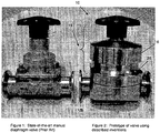
- Figure 1 shows a standard diaphragm valve that is known in the art.
- Standard tools and fasteners for a flanged bonnet on such a diaphragm valve require removal of several pieces in order to replace or access the wear part (diaphragm).
- a "typical" flange on a one-inch valve requires four bolts, four nuts, and eight washers, for a total of sixteen loose parts.
- Stainless steel bolts are prone to galling and the joint is prone to leakage if the bolts are under loaded.
- Screw threads, and holes in the body and bonnet flanges, which are partially covered by the bolt head or nut provide areas of entrapment for cleaning solutions and bacteria, which is highly undesirable in biopharmaceutical manufacturing applications.
- a key performance weakness of the standard joint is that the body to bonnet connection also provides the flange seal loading. This reduces the ability for the flange seal to be compliant to thermal expansion of the seal, for if it is made compliant with a reduced spring constant, that lower spring constant will allow the body and bonnet seal flanges to separate when the compressor load is applied for valve closure.
- the present invention may take the form of apparatus, including a diaphragm valve, that features a valve body and a bonnet assembly.
- the valve body is configured with a passage to be opened to allow fluid to pass through the valve body and to be closed to prevent fluid from passing through the valve body.
- the bonnet assembly has a compressor, a pressure ring, and a diaphragm, where the pressure ring is configured to load and unload the diaphragm based at least partly on a first spring constant to seal a peripheral portion of the diaphragm, and the compressor configured to close or open the passage of the valve body.
- the valve body and bonnet assembly are configured with a connection that allows the valve body and bonnet assembly to be substantially fixed together with a second spring constant that is substantially higher than and independent from the first spring constant, wherein the connection is a rotational connection.
- the rotational connection may include, or take the form of, the valve body having a rim or surface configured with at least two shouldered pins arranged on opposite sides of the valve body; and the bonnet assembly having a corresponding rim or surface configured with at least two keyways arranged on opposite sides of the bonnet assembly, and each keyway being recessed and configured to receive and engage a respective shouldered pin when the bonnet assembly is rotated in relation to the valve body.
- each shouldered pin may be configured with one end coupled to the rim or surface and another end with a shouldered portion; and each keyway may include a first opening portion configured to receive a respective shoulder portion of the respective shouldered pin, and each keyway may include a second opening portion configured to receive and engage the respective shoulder portion when the respective shouldered pin is inserted into a respective keyway and the bonnet assembly is rotated in relation to the valve body.
- the bonnet assembly may include a cover configured to be rotated to cause the pressure ring to seal the peripheral portion of the diaphragm based at least partly on the first spring constant.
- the cover may be configured to attach to and rotate a central gear to cause the pressure ring to seal the peripheral portion of the diaphragm
- the central gear may be configured to turn multiple gear-headed screws that compress one or more spring disc washers, which drives the pressure ring that compresses the diaphragm against the valve body to seal the peripheral portion of the diaphragm.
- the valve body may be configured with multiple shouldered pins, including four, arranged in a circular pattern, substantially equi-distant in relation to one another on the rim or surface; and the bonnet assembly may be configured with multiple keyways, including four, arranged in a corresponding circular pattern as the multiple shoulder pins.
- the bonnet assembly may be configured with a central load thread mechanism that includes a bonnet portion having threads; a nut portion having corresponding threads and being configured to engage the pressure ring, so that when the nut portion is rotated the pressure ring loads or unloads the diaphragm based at least partly on the first spring constant to seal the peripheral portion of the diaphragm, and the compressor configured to close or open the passage.
- a central load thread mechanism that includes a bonnet portion having threads; a nut portion having corresponding threads and being configured to engage the pressure ring, so that when the nut portion is rotated the pressure ring loads or unloads the diaphragm based at least partly on the first spring constant to seal the peripheral portion of the diaphragm, and the compressor configured to close or open the passage.
- the rotation connection may include the valve body being configured with a surface and at least two radially-extending flange portions arranged on opposite sides of the valve body; and the bonnet assembly having a corresponding surface configured with at least two channel portions, each channel portion being recessed and configured to receive and engage a respective radially-extending flange portion when the bonnet assembly is rotated in relation to the valve body.
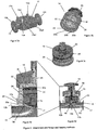
- FIGS 2 and 3 show apparatus generally indicated as 10, such as a diaphragm valve, according to some embodiments of the present invention.
- the diaphragm valve 10 includes a valve body 12 and a bonnet assembly generally indicated as 14.
- the valve body 12 is configured with a passage 13 to be opened to allow fluid to pass through the valve body and to be closed to prevent fluid from passing through the valve body 12.
- the bonnet assembly 14 has a compressor 15, a pressure ring 34, and a diaphragm 17.
- the pressure ring 34 is configured to load and unload the diaphragm 17 based at least partly on a first spring constant to seal a peripheral portion 17a of the diaphragm 17.
- the compressor 15 is -configured to close or open the passage 13 of the valve body 12.
- valve body 12 and bonnet assembly 14 are configured with a connection or attachment, e.g., which may be a rotational connection or attachment, that allows the valve body 12 and the bonnet assembly 14 to be substantially fixed together with a second spring constant that is substantially higher than and independent from the first spring constant.
- a connection or attachment e.g., which may be a rotational connection or attachment
- Figures 3a to 3g show one version of the rotational connection or attachment
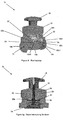
- Figures 4a to 4c show another version of the rotational connection or attachment, all according to some embodiments of the present invention.
- the valve body 12 includes at least two shouldered pins, studs or bolts 12a, two ports 12b, 12c, a weir (dam) portion 12d, and a rim or surface 12e.
- the bonnet assembly 14 includes a cover 16, a knob 18, a bonnet portion 20 having a rim or surface 20a and at least two keyways 22.
- one part of the rotation connection include the rim or surface 12e being configured with the at least two shouldered pins 12a arranged on opposite sides of the valve body 12.
- the rim or surface 12e is shown configured with four shouldered pins 12a arranged in a circular pattern, substantially equi-distant on the rim or surface 12e.
- each shouldered pin 12a may be configured with one end 12a 1 coupled to the rim or surface 12e and another end with a shouldered portion 12a 2 .
- the other part of the rotational connection includes the corresponding rim or surface 20a being configured with the at least two keyways 22 arranged on opposite sides of the bonnet assembly 14.
- each keyway 22 is recessed into the corresponding rim or surface 20a and is configured to receive and engage a respective shouldered pin 12a when the bonnet assembly 14 is rotated in relation to the valve body 12.
- the rim or surface is shown configured with four keyways 22 arranged in a corresponding circular pattern as the four shoulder pins 12a on the rim or surface 20a.
- each keyway 22 may include a first opening portion 22a configured to receive a respective shoulder portion 12a 2 of the respective shouldered pin 12a.
- Each keyway may also include a second opening portion 22b configured to receive and engage the respective shoulder portion 12a 2 when the respective shouldered pin 12a is inserted into a respective keyway 22 and the bonnet assembly 14 is rotated in relation to the valve body 12.
- the shoulder portion 12a 2 of the respective shouldered pin 12a is dimensioned to be smaller than the first opening portion 22a so as to pass through and into same, and is dimensioned to be larger than the second opening portion 22b so as to engaged and retained therein.
- the shoulder portion 12a 2 is configured with a shoulder rim portion 12a 3
- the second opening portion 22b is configured with a second opening rim portion 12c
- a detent in two or more of the keyways 22 may be used to insure that the bonnet assembly 14 and the valve body 12 cannot rotationally disengage once the load is applied, as the shouldered pins 12a will be loaded into the detents.
- the gear-headed screws 30 each have an end screw portion 30a configured to compress one or more spring disc washer(s) 31 and the Belleville springs 32 (see Figures 3e and 3g ), which in turn drive the pressure ring 34 that provides the low spring constant pressure and compresses the peripheral portion 17a of the gasket or diaphragm 17 against the rim or surface 12e of the valve body or body flange 12 to seal the peripheral portion 17a of the diaphragm 17, as best shown in Figure 3e .
- the screws 30 force the bonnet portion 20 apart from the combination of the one or more spring disc washer(s) 31, the Belleville springs 32 and the pressure ring 34, thereby providing a downward force on the pressure ring 34 to seal the diaphragm 17, and an upward force on the bonnet portion 20 to fix or retain the respective shouldered pin 12a in the respective keyway 22.
- the reader is also referred to patent application serial no. 13/554,541, filed 20 July 2012 (911-002.051//F-EV-1202US), for alternative techniques for sealing the rim, surface or flange portion of the valve body with the peripheral portion of the diaphragm.
- the compressor 15 is configured to respond to the turning of the knob 18, and to close the valve passageway by causing a central part 17b of the diaphragm 17 to seal the weir portion 12d to prevent fluid from passing through the valve body 12, as best shown in Figure 3d .
- the scope of the present invention is not limited to manual actuation of the compressor 15, since embodiments are envisioned using non-manual actuation of the compressor.
- other types or kinds of actuation may be used that provide thrust to the compressor 15, including, but not limited to manual, pneumatic, hydraulic, and electric motor actuation.
- the reader is also referred to patent application serial no.
- a key feature to the present invention is that this rotational connection or attachment method shown in Figures 2 and 3a to 3f allows the valve body 12 to bonnet assembly 14 to be essentially fixed with a very high spring constant, and independent from the compliant, lower spring constant, loading of the flanged seal. Due to these being independent features, another advantage of the present invention is that the compressor load applied by compressor 15, which closes the diaphragm 17, is resisted by the high spring constant shouldered pins or bolts without disturbing the lower spring constant flange seal which allows compliance for thermal expansion and creep reduction of the seal.
- Another advantage of the present invention is the ability to make the valve body 12 to bonnet assembly 14 connection prior to energizing the flanged joint seal. This allows for simplicity and quick attachment/release of the connection.
- the keyways 22 may be configured to fully enclose the studs as shown, or may only encase only the neck of the studs.
- Other simple "slide on " attachment methods may also be used prior to the load introduction.
- the force applied by the pressure ring 34 can be achieved by replacement of the gear-headed screws 30 (see Figures 3c to 3e ) with standard screws or threads that can be turned down incrementally in a bolt pattern.
- Figures 3a to 3g show other parts or elements that form part of the diaphragm valve 10, but do not form part of the underlying invention, including a compressor pin 40, O-rings, and are thus not discussed in detail.
- Figures 4a to 4c show the other version of the rotational connection or attachment for a diaphragm valve generally indicated as 50 having a valve body 52 and a bonnet assembly 54, according to some embodiments of the present invention.
- Parts in Figures 4a to 4b that are similar to parts in Figures 3a to 3g have similar part labels, e.g., including the ports 12b, 12c and the passage 13 of the valve body 52.
- the rotation connection may include the valve body 52 being configured with a surface and at least two radially-extending flange portions 56 arranged on opposite sides of the valve body 52.
- the bonnet assembly 54 has a bonnet portion 55 having a corresponding surface 54a configured with at least two channel portions 58. Each channel portion 58 is recessed and configured to receive and engage a respective radially-extending flange portion 56 when the bonnet assembly is rotated in relation to the valve body. Consistent with that set forth above, The rotational connection or attachment allows the valve body 52 and the bonnet assembly 54 to be substantially fixed together with a second spring constant that is substantially higher than and independent from a first spring constant.
- the flange spring load may also be achieved by other means, such as a central thread.
- Figure 4c shows an example of an alternative central load thread mechanism, including a cross sectional view showing centralized threads 55a.
- the diaphragm valve. 50 may be configured with a central loaded thread mechanism that forms part of the bonnet assembly 54, according to some embodiments of the present invention.
- the central load thread mechanism may include the bonnet portion 55 having threads 55a; a nut portion 60 having corresponding threads 60a and being configured to engage a spindle 51 , so that when the nut portion 60 is rotated the pressure ring 34 loads or unloads the diaphragm 17 based at least partly on the first spring constant to close or open the passage 12c.
Landscapes
- Engineering & Computer Science (AREA)
- General Engineering & Computer Science (AREA)
- Mechanical Engineering (AREA)
- Valve Housings (AREA)
- Safety Valves (AREA)
Claims (8)
- Appareil (10, 50), incluant une vanne à membrane, comprenant :un corps de vanne (12, 52) conçu avec un passage (13) destiné à être ouvert pour permettre à un fluide de traverser le corps de vanne (12) et destiné à être fermé pour empêcher un fluide de traverser le corps de vanne (12);un ensemble chapeau (14, 54) comportant un compresseur (15), une bague de pression (34) et une membrane (17), la bague de pression (34) conçue pour charger et décharger la membrane (17) sur la base au moins partiellement d'une première constante de rappel pour sceller une partie périphérique (17a) de la membrane (17) et le compresseur (15) conçu pour fermer ou ouvrir le passage (13) du corps de vanne (12) ;le corps de vanne (12) et l'ensemble chapeau (14) sont sensiblement fixés l'un à l'autre avec une seconde constante de rappel qui est sensiblement plus élevée que la première constante de rappel et indépendante de cette dernière,caractérisé en ce que le corps de vanne (12) et l'ensemble chapeau (14) sont conçus avec une liaison rotative, cette dernière incluant:le corps de vanne (12) présentant un rebord ou une surface (12e) conçu avec au moins deux broches à épaulement (12a) disposées sur des côtés opposés du corps de vanne (12) ; etl'ensemble chapeau (14) comportant un rebord ou une surface (20a) correspondant conçu avec au moins deux rainures de clavette (22) disposées sur des côtés opposés de l'ensemble chapeau (14),chaque rainure de clavette (22) étant évidée et conçue pour recevoir et mettre en prise une broche à épaulement (12a) respective lorsque l'ensemble chapeau (14) est mis en rotation par rapport au corps de vanne (12).
- Appareil (10, 50), incluant une vanne à membrane, comprenant :un corps de vanne (12, 52) conçu avec un passage (13) destiné à être ouvert pour permettre à un fluide de traverser le corps de vanne (12, 52) et destiné à être fermé pour empêcher un fluide de traverser le corps de vanne (12, 52);un ensemble chapeau (14, 54) comportant un compresseur (15), une bague de pression (34) et une membrane (17), la bague de pression (34) conçue pour charger et décharger la membrane (17) sur la base au moins partiellement d'une première constante de rappel pour sceller une partie périphérique (17a) de la membrane (17) et le compresseur (15) conçu pour fermer ou ouvrir le passage (13) du corps de vanne (12, 52) ;le corps de vanne (12, 52) et l'ensemble chapeau (14, 54) sont sensiblement fixés l'un à l'autre avec une seconde constante de rappel qui est sensiblement plus élevée que la première constante de rappel etindépendante de cette dernière,caractérisé en ce que le corps de vanne (52) et l'ensemble chapeau (54) sont conçus avec une liaison rotative, cette dernière comportant:le corps de vanne (52) étant conçu avec une surface (52a) et au moins deux parties de bride (56) s'étendant radialement disposées sur des côtés opposés du corps de vanne (12) ; etl'ensemble chapeau (54) comportant une surface correspondante (54a) conçue avec au moins deux parties de canal (58), chaque partie de canal (58) étant évidée et conçue pour recevoir et mettre en prise une partie de bride (56) respective s'étendant radialement lorsque l'ensemble chapeau (14) est mis en rotation par rapport au corps de vanne (12).
- Appareil (10) selon la revendication 1, dans lequel chaque broche à épaulement (12a) est conçue avec une extrémité (12a1) couplée au rebord ou à la surface (12e) et une autre extrémité avec une partie à épaulement (12a2) ; et chaque rainure d e clavette (22) comporte une première partie d'ouverture (22a) conçue pour recevoir une partie d'épaulement (12a2) respective de la broche à épaulement (12a) respective et chaque rainure de clavette (22) comporte une seconde partie d'ouverture (22b) conçue pour recevoir et mettre en prise la partie d'épaulement (12a2) respective lorsque la broche à épaulement (12a) respective est insérée dans une rainure de clavette (22) respective et que l'ensemble chapeau (14) est mis en rotation par rapport au corps de vanne (12).
- Appareil (10) selon la revendication 1 ou 2, dans lequel l'ensemble chapeau (14) comprend un couvercle (16) conçu pour être mis en rotation pour amener la bague de pression (34) à sceller la partie périphérique (17a) de la membrane (17) sur la base au moins partiellement de la première constante de rappel.
- Appareil (10) selon la revendication 4, dans lequel le couvercle (16) est conçu pour se fixer sur et faire tourner un engrenage central (28) pour amener la bague de pression (34) à sceller la partie périphérique (17a) de la membrane (17).
- Appareil (10) selon la revendication 5, dans lequel l'engrenage central (28) est conçu pour faire tourner plusieurs vis à tête d'engrenage (30) qui compriment une ou plusieurs rondelles de disque à ressort (31), ce qui entraîne la bague de pression (34) qui comprime la membrane (17) contre le corps de vanne (12) à sceller la partie périphérique (17a) de la membrane (17).
- Appareil (10) selon la revendication 1, dans lequel le corps de vanne (12) est conçu avec plusieurs broches à épaulement (12a), incluant quatre broches à épaulement (12a), disposées dans un motif circulaire, en relation sensiblement équidistante les unes par rapport aux autres sur le rebord ou la surface (12e) ; et l'ensemble chapeau (14) peut être conçu avec plusieurs rainures de clavette (22), incluant quatre rainures de clavette (22), disposées dans un motif circulaire correspondant à celui des multiples broches à épaulement (12a).
- Appareil (10) selon la revendication 1 ou 2, dans lequel l'ensemble chapeau (14) est conçu avec un mécanisme de filetage à charge centrale qui inclut une partie de couvercle (55) comportant des filetages (55a) ; et une partie d'écrou (60) comportant des filetages correspondants (60a) et étant conçue pour mettre en prise les ressorts élastiques métalliques (32), de sorte que, lorsque la partie d'écrou (60) est mise en rotation, la bague de pression (34) charge ou décharge la membrane (17) sur la base au moins partiellement de la première constante de rappel pour sceller la partie périphérique (17a) de la membrane (17) et le compresseur (15) conçu pour fermer ou ouvrir le passage (13).
Applications Claiming Priority (2)
| Application Number | Priority Date | Filing Date | Title |
|---|---|---|---|
| US13/554,532 US9016307B2 (en) | 2012-07-20 | 2012-07-20 | Quick connect, post energized flanged joint for a diaphragm valve |
| PCT/US2013/051428 WO2014015326A1 (fr) | 2012-07-20 | 2013-07-22 | Joint à bride post-excité à branchement rapide pour robinet à membrane |
Publications (3)
| Publication Number | Publication Date |
|---|---|
| EP2875266A1 EP2875266A1 (fr) | 2015-05-27 |
| EP2875266B1 EP2875266B1 (fr) | 2016-09-14 |
| EP2875266B2 true EP2875266B2 (fr) | 2020-04-29 |
Family
ID=48951572
Family Applications (1)
| Application Number | Title | Priority Date | Filing Date |
|---|---|---|---|
| EP13766163.3A Active EP2875266B2 (fr) | 2012-07-20 | 2013-07-22 | Joint à bride post-excité à branchement rapide pour robinet à membrane |
Country Status (4)
| Country | Link |
|---|---|
| US (1) | US9016307B2 (fr) |
| EP (1) | EP2875266B2 (fr) |
| MX (2) | MX357260B (fr) |
| WO (1) | WO2014015326A1 (fr) |
Families Citing this family (17)
| Publication number | Priority date | Publication date | Assignee | Title |
|---|---|---|---|---|
| US11326712B2 (en) | 2012-12-31 | 2022-05-10 | Baker Hughes Oilfield Operations Llc | No-bolt valve assembly system |
| US9709189B2 (en) * | 2014-02-28 | 2017-07-18 | Itt Manufacturing Enterprises Llc | Final position locking feature of multi-turn rotational device having an axially translating wheel or a clocked lock passage gear |
| DE202014102658U1 (de) | 2014-06-06 | 2014-06-23 | Bürkert Werke GmbH | Membranventil |
| DE102014013512A1 (de) * | 2014-09-11 | 2016-03-17 | Festo Ag & Co. Kg | Membranventil |
| DE102015202775B4 (de) | 2015-02-16 | 2018-10-04 | Festo Ag & Co. Kg | Membranventil |
| CN105012080B (zh) * | 2015-06-12 | 2019-04-16 | 湖北立天生物工程有限公司 | 一种体表高抗菌超吸水透气的健康功能清爽卫生巾 |
| DE102016123606A1 (de) * | 2016-12-06 | 2018-06-07 | Gemü Gebr. Müller Apparatebau Gmbh & Co. Kommanditgesellschaft | Antriebsbaugruppe eines Membranventils und Verfahren zur Montage einer Antriebsbaugruppe |
| US20190323625A1 (en) | 2018-04-23 | 2019-10-24 | Rain Bird Corporation | Valve With Reinforcement Ports And Manually Removable Scrubber |
| MX2021009945A (es) * | 2019-02-20 | 2021-10-13 | Itt Mfg Enterprises Llc | Anillo de presion de transicion. |
| MX2021009961A (es) * | 2019-02-20 | 2021-12-10 | Itt Mfg Enterprises Llc | Estructura de codificacion. |
| US11236833B2 (en) * | 2020-06-26 | 2022-02-01 | Itt Manufacturing Enterprises Llc | Diaphragm valve with plastic diaphragm |
| DE202020105933U1 (de) | 2020-10-16 | 2020-11-17 | Samson Aktiengesellschaft | Deckel mit Verschluss |
| DE102021108093A1 (de) | 2021-03-30 | 2022-10-06 | Gemü Gebr. Müller Apparatebau Gmbh & Co. Kommanditgesellschaft | Membranventil |
| CN117480335A (zh) * | 2021-04-16 | 2024-01-30 | 道格拉斯·亚瑟·纽伯格 | 阀门致动器组件 |
| US12117090B2 (en) * | 2021-08-04 | 2024-10-15 | Gemü Gebr. Müller Apparatebau Gmbh & Co. Kommanditgesellschaft | Tensioning assembly for a process valve |
| AU2022204325B1 (en) * | 2021-11-05 | 2022-12-15 | Fst Innovation Pty Ltd | Tamper switch, tamper resistant valve and valve monitor |
| DE102023105816A1 (de) * | 2023-03-09 | 2024-09-12 | Sed Flow Control Gmbh | Membranventil |
Citations (4)
| Publication number | Priority date | Publication date | Assignee | Title |
|---|---|---|---|---|
| JPH0193674A (ja) † | 1987-10-02 | 1989-04-12 | Koganei Seisakusho:Kk | 弁 |
| US5326078A (en) † | 1993-07-08 | 1994-07-05 | Benkan Corporation | Metal diaphragm valve |
| DE10153362A1 (de) † | 2001-10-29 | 2003-05-08 | Gaida Gregor | Membranventil |
| DE112004001268T5 (de) † | 2003-07-11 | 2006-07-13 | Entegris, Inc., Chaska | Ventil und Membran für langen Hub |
Family Cites Families (76)
| Publication number | Priority date | Publication date | Assignee | Title |
|---|---|---|---|---|
| GB685935A (fr) | 1900-01-01 | |||
| US195596A (en) | 1877-09-25 | Improvement in gas-regulators | ||
| FR511989A (fr) | 1920-03-18 | 1921-01-08 | Nicolas Herzmark | Robinet plus spécialement destiné aux fluides à pression élevée |
| US1609813A (en) | 1926-02-08 | 1926-12-07 | James C Gorman | Power diaphragm pump |
| US1992043A (en) | 1932-06-24 | 1935-02-19 | Saunders Philip Keith | Diaphragm valve |
| US2388989A (en) | 1944-04-08 | 1945-11-13 | Shriver & Company Inc T | Diaphragm valve |
| US2582996A (en) | 1945-03-02 | 1952-01-22 | Milton P Laurent | Seal for gate valve bonnets |
| US2504057A (en) | 1945-06-22 | 1950-04-11 | Crane Co | Diaphragm valve |
| US2710629A (en) | 1950-02-03 | 1955-06-14 | Saunders Vaive Company Ltd | Flexible diaphragms |
| US2717757A (en) | 1950-04-07 | 1955-09-13 | Kirkhill Inc | Valve means |
| GB794992A (en) | 1954-06-14 | 1958-05-14 | Grinnell Corp | Diaphragm valves |
| US2872935A (en) | 1955-02-28 | 1959-02-10 | Robert W Kenney | Valve mechanism |
| US3026852A (en) | 1959-05-07 | 1962-03-27 | Kelsey Hayes Co | Booster motor mechanism |
| US3067764A (en) | 1960-04-27 | 1962-12-11 | Ladish Co | Diaphragm valves |
| US3204919A (en) | 1961-07-31 | 1965-09-07 | Tripoli | Split sleeve control valve |
| US3148861A (en) | 1962-06-27 | 1964-09-15 | Hills Mccanna Co | Weir valve |
| GB1011970A (en) | 1962-08-20 | 1965-12-01 | Hills Mccanna Co | Flexible valve diaphragms |
| US3257095A (en) | 1962-12-12 | 1966-06-21 | Chester A Siver | Valve construction particularly packed or sealed |
| BE654380A (fr) | 1963-10-14 | |||
| US3349795A (en) | 1964-04-22 | 1967-10-31 | Ngk Insulators Ltd | Diaphragm valve including a snap ring connection |
| US3521667A (en) | 1968-01-22 | 1970-07-28 | Fisher Governor Co | Control valve |
| US3561480A (en) | 1968-05-27 | 1971-02-09 | Wayne K Fairchild | Fluid mixing apparatus |
| BE755469A (fr) | 1969-08-29 | 1971-02-01 | Hayday Valve And Equipement Cy | Perfectionnements aux soupapes |
| US3631882A (en) | 1970-01-29 | 1972-01-04 | Grinnell Corp | Diaphragm valve |
| US3811649A (en) | 1972-07-20 | 1974-05-21 | Resistoflex Corp | Constrictable tube valve with plural wall tube |
| US3982729A (en) | 1974-03-14 | 1976-09-28 | Kerotest Manufacturing Corporation | Back-up seal for diaphragm valve |
| US4014514A (en) | 1975-06-27 | 1977-03-29 | Hills-Mccanna Company | High pressure diaphragm valve |
| US4026513A (en) | 1975-11-06 | 1977-05-31 | Grove Valve And Regulator Company | Pilot valve |
| US4077605A (en) | 1975-12-11 | 1978-03-07 | Kutz Hugo Joseph | Sealed cartridge valve assembly |
| US4214604A (en) | 1978-02-06 | 1980-07-29 | Rumsey Rollin D | Straight through flow diaphragm valve structures |
| US4295485A (en) | 1978-04-26 | 1981-10-20 | Waterfield Engineering Limited | Diaphragm valve |
| US4231549A (en) | 1978-12-11 | 1980-11-04 | Kerotest Manufacturing Corp. | Valve stem and valve disc connection for a diaphragm valve |
| EP0023409A1 (fr) | 1979-07-28 | 1981-02-04 | Waterfield Engineering Limited | Soupapes à diaphragme |
| CA1191419A (fr) | 1981-01-16 | 1985-08-06 | Waterfield Engineering Limited | Perfectionnement dans ou en rapport avec des robinets a clapet souple |
| US4452428A (en) | 1981-12-24 | 1984-06-05 | Scaramucci John P | Bonnet locking system for a valve |
| US4498798A (en) | 1983-09-26 | 1985-02-12 | Amsted Industries Incorporated | Locating pin |
| DE3447329A1 (de) | 1984-12-24 | 1986-07-03 | Saunders-Sisto Armaturen S.A., Mersch | Membranventil |
| GB2173882B (en) | 1985-04-11 | 1988-11-23 | Kim Prod Ltd | Improvement in diaphragm valves for corrosive liquids |
| US4750709A (en) | 1986-05-16 | 1988-06-14 | Nupro Company | Diaphragm valve |
| US4746095A (en) | 1987-09-14 | 1988-05-24 | Anderson, Greenwood & Co. | Bonnet lock |
| US5029813A (en) | 1990-08-06 | 1991-07-09 | Fisher Controls International, Inc. | Diaphragm stem seal attachment |
| US5295662A (en) | 1991-08-26 | 1994-03-22 | Masako Kiyohara | Fluid flow-controller with improved diaphragm |
| SE501377C2 (sv) | 1993-06-17 | 1995-01-30 | Ingvar Baecklund | Trevägs membranventilanordning |
| JP3287663B2 (ja) * | 1993-09-17 | 2002-06-04 | 清原 まさ子 | 制御器 |
| US5411350A (en) | 1993-11-03 | 1995-05-02 | Loctite Corporation | Quick connect/disconnect device, and dispensing apparatus comprising same |
| US5551477A (en) | 1994-07-08 | 1996-09-03 | Kabushiki-Kaisha Motoyama Seisakusho | Diaphragm-type flow control valve and manual control valve apparatus |
| US5597184A (en) | 1994-09-30 | 1997-01-28 | High Vacuum Apparatus Mfg., Inc. | Quick release clamp for bonnet and flange of gate valves |
| JP3469331B2 (ja) | 1994-10-17 | 2003-11-25 | 株式会社フジキン | 金属製ダイヤフラムの内周縁部のシール構造 |
| JP3291151B2 (ja) | 1995-02-15 | 2002-06-10 | 株式会社フジキン | ダイヤフラム弁 |
| AU6681496A (en) | 1995-07-28 | 1997-02-26 | Myron Keller | Apparatus and method for reducing water use |
| SE510424C2 (sv) | 1995-11-10 | 1999-05-25 | Robovalve Ab | Membranventil |
| DE19715164A1 (de) | 1997-04-11 | 1998-10-22 | Fischer Georg Rohrleitung | Membranventil |
| NZ332927A (en) | 1997-05-28 | 2000-07-28 | Tetra Laval Holdings & Finance | Double-Seated Valve for aseptic application |
| ATE211531T1 (de) | 1997-08-14 | 2002-01-15 | Fischer Georg Rohrleitung | Membranventil |
| US6155535A (en) | 1997-12-09 | 2000-12-05 | Marcilese; Joseph Peter | Diaphragm compression limit stops |
| US6227520B1 (en) | 1999-01-19 | 2001-05-08 | New York Air Brake Corporation | Diaphragm piston valve |
| EP1161635A4 (fr) * | 1999-02-19 | 2004-09-08 | Automatic Switch Co | Vanne proportionnelle a plage de fonctionnement etendue |
| US6443426B1 (en) | 1999-07-07 | 2002-09-03 | Arthur Brenes | Slide lock for vacuum valve |
| US6508266B2 (en) | 2000-03-31 | 2003-01-21 | Toyo Stainless Steel Industries Co., Ltd. | Diaphragm valve |
| US6296227B1 (en) | 2000-05-24 | 2001-10-02 | Anthony Manufacturing Corporation Commercial Products Division | Valve assembly with clamp on bonnet |
| US6845959B2 (en) | 2001-05-04 | 2005-01-25 | Hydril Company, L.P. | Quick release blowout preventer bonnet |
| CA2452809C (fr) | 2002-12-10 | 2012-05-29 | Montreal Bronze Foundry Limited | Robinet a membrane comprenant un dispositif de fermeture reglable |
| JP4387665B2 (ja) | 2002-12-25 | 2009-12-16 | 株式会社フジキン | 流体制御器 |
| US20050045847A1 (en) | 2003-08-25 | 2005-03-03 | Powell Douglas H. | Key operational valve |
| JP2006090386A (ja) | 2004-09-22 | 2006-04-06 | Kitz Sct:Kk | ダイヤフラムバルブ |
| JP5138863B2 (ja) | 2004-12-10 | 2013-02-06 | Ckd株式会社 | ダイアフラム弁 |
| US7789012B2 (en) | 2005-04-25 | 2010-09-07 | Aquasyn, Llc | Valve bonnet assembly |
| ITMI20060591A1 (it) | 2006-03-29 | 2007-09-30 | Faster Spa | Innesto rapido |
| EP2064468B1 (fr) | 2006-09-18 | 2011-07-06 | Karl Locher | Soupape d'arrêt avec fonction de fuite |
| US8056578B2 (en) | 2007-01-31 | 2011-11-15 | Moen Incorporated | Valve cartridge with lobular key |
| JP2008190546A (ja) | 2007-01-31 | 2008-08-21 | Iwai Kikai Kogyo Co Ltd | ダイヤフラムバルブにおけるダイヤフラムの固定構造 |
| GB2460227A (en) | 2008-05-19 | 2009-11-25 | Walker & Co James Ltd | Valve diaphragm |
| DE102009023002B4 (de) | 2009-05-28 | 2012-02-09 | G.S. Anderson Gmbh | Membranventil-Antrieb |
| EP2459907A1 (fr) | 2009-07-27 | 2012-06-06 | Merck Sharp & Dohme Corp. | Soupape à diaphragme présentant une étanchéité et une détection des fuites améliorées |
| US8708308B2 (en) | 2009-08-05 | 2014-04-29 | Itt Manufacturing Enterprises, Inc. | Sealing arrangement for a diaphragm valve |
| US8714517B2 (en) | 2010-09-20 | 2014-05-06 | Fisher Controls International, Llc | Bonnet apparatus to provide live-loading to a seal |
-
2012
- 2012-07-20 US US13/554,532 patent/US9016307B2/en active Active
-
2013
- 2013-07-22 MX MX2015000856A patent/MX357260B/es active IP Right Grant
- 2013-07-22 MX MX2017014587A patent/MX364089B/es unknown
- 2013-07-22 WO PCT/US2013/051428 patent/WO2014015326A1/fr not_active Ceased
- 2013-07-22 EP EP13766163.3A patent/EP2875266B2/fr active Active
Patent Citations (4)
| Publication number | Priority date | Publication date | Assignee | Title |
|---|---|---|---|---|
| JPH0193674A (ja) † | 1987-10-02 | 1989-04-12 | Koganei Seisakusho:Kk | 弁 |
| US5326078A (en) † | 1993-07-08 | 1994-07-05 | Benkan Corporation | Metal diaphragm valve |
| DE10153362A1 (de) † | 2001-10-29 | 2003-05-08 | Gaida Gregor | Membranventil |
| DE112004001268T5 (de) † | 2003-07-11 | 2006-07-13 | Entegris, Inc., Chaska | Ventil und Membran für langen Hub |
Also Published As
| Publication number | Publication date |
|---|---|
| MX2015000856A (es) | 2015-03-11 |
| US9016307B2 (en) | 2015-04-28 |
| US20140020769A1 (en) | 2014-01-23 |
| EP2875266A1 (fr) | 2015-05-27 |
| MX364089B (es) | 2019-04-12 |
| MX357260B (es) | 2018-07-03 |
| EP2875266B1 (fr) | 2016-09-14 |
| WO2014015326A1 (fr) | 2014-01-23 |
Similar Documents
| Publication | Publication Date | Title |
|---|---|---|
| EP2875266B2 (fr) | Joint à bride post-excité à branchement rapide pour robinet à membrane | |
| US11512783B2 (en) | Valve assemblies and associated components | |
| CA2705287C (fr) | Dispositif de regulation d'ecoulement de fluide comportant un dispositif de retenue de bague de siege | |
| US8813771B2 (en) | Gate valve | |
| US20030196698A1 (en) | Axial flow control valve | |
| EP3446007B1 (fr) | Vanne de régulation rotative présentant un siège de vanne serré | |
| US20130026397A1 (en) | Planetary gear ball valve | |
| CN204784735U (zh) | 用于接近和对准密封盘的装置 | |
| US20210239220A1 (en) | Replaceable Seat Pocket Assembly | |
| WO2016019470A1 (fr) | Ensemble vanne | |
| US20250189045A1 (en) | Clamped diaphragm valve assembly | |
| US4512359A (en) | Valve mechanism with replaceable seal rings | |
| CA2724619A1 (fr) | Appareil de retenue des pieces internes de robinets | |
| JP7675216B2 (ja) | バルブ用コック及びバルブ用コックを備えるバルブ | |
| US10215290B2 (en) | Plug with attachable upper trunnion | |
| US20160076669A1 (en) | Balanced globe valve assembly | |
| US20220128162A1 (en) | Keying structure | |
| EP3286463B1 (fr) | Palier pour soupape de commande rotative | |
| CN223120679U (zh) | 一种偏心半球阀 | |
| US20250012363A1 (en) | Fixed seat shut-off valve and process for assembling the same | |
| CA3130065C (fr) | Structure de clavette pour un assemblage de chapeau d'un robinet a membrane | |
| CA3022288C (fr) | Obturateur avec tourillon superieur pouvant etre attache | |
| RU2470209C2 (ru) | Задвижка запорная | |
| GB2539024A (en) | Pressure balancing globe valve |
Legal Events
| Date | Code | Title | Description |
|---|---|---|---|
| PUAI | Public reference made under article 153(3) epc to a published international application that has entered the european phase |
Free format text: ORIGINAL CODE: 0009012 |
|
| 17P | Request for examination filed |
Effective date: 20150218 |
|
| AK | Designated contracting states |
Kind code of ref document: A1 Designated state(s): AL AT BE BG CH CY CZ DE DK EE ES FI FR GB GR HR HU IE IS IT LI LT LU LV MC MK MT NL NO PL PT RO RS SE SI SK SM TR |
|
| AX | Request for extension of the european patent |
Extension state: BA ME |
|
| DAX | Request for extension of the european patent (deleted) | ||
| GRAP | Despatch of communication of intention to grant a patent |
Free format text: ORIGINAL CODE: EPIDOSNIGR1 |
|
| INTG | Intention to grant announced |
Effective date: 20160218 |
|
| GRAS | Grant fee paid |
Free format text: ORIGINAL CODE: EPIDOSNIGR3 |
|
| GRAA | (expected) grant |
Free format text: ORIGINAL CODE: 0009210 |
|
| AK | Designated contracting states |
Kind code of ref document: B1 Designated state(s): AL AT BE BG CH CY CZ DE DK EE ES FI FR GB GR HR HU IE IS IT LI LT LU LV MC MK MT NL NO PL PT RO RS SE SI SK SM TR |
|
| REG | Reference to a national code |
Ref country code: GB Ref legal event code: FG4D |
|
| REG | Reference to a national code |
Ref country code: CH Ref legal event code: EP |
|
| REG | Reference to a national code |
Ref country code: IE Ref legal event code: FG4D |
|
| REG | Reference to a national code |
Ref country code: AT Ref legal event code: REF Ref document number: 829382 Country of ref document: AT Kind code of ref document: T Effective date: 20161015 |
|
| REG | Reference to a national code |
Ref country code: DE Ref legal event code: R096 Ref document number: 602013011666 Country of ref document: DE |
|
| REG | Reference to a national code |
Ref country code: SE Ref legal event code: TRGR |
|
| REG | Reference to a national code |
Ref country code: NL Ref legal event code: FP |
|
| REG | Reference to a national code |
Ref country code: CH Ref legal event code: NV Representative=s name: BRAUNPAT BRAUN EDER AG, CH |
|
| REG | Reference to a national code |
Ref country code: LT Ref legal event code: MG4D |
|
| PG25 | Lapsed in a contracting state [announced via postgrant information from national office to epo] |
Ref country code: LT Free format text: LAPSE BECAUSE OF FAILURE TO SUBMIT A TRANSLATION OF THE DESCRIPTION OR TO PAY THE FEE WITHIN THE PRESCRIBED TIME-LIMIT Effective date: 20160914 Ref country code: HR Free format text: LAPSE BECAUSE OF FAILURE TO SUBMIT A TRANSLATION OF THE DESCRIPTION OR TO PAY THE FEE WITHIN THE PRESCRIBED TIME-LIMIT Effective date: 20160914 Ref country code: NO Free format text: LAPSE BECAUSE OF FAILURE TO SUBMIT A TRANSLATION OF THE DESCRIPTION OR TO PAY THE FEE WITHIN THE PRESCRIBED TIME-LIMIT Effective date: 20161214 Ref country code: RS Free format text: LAPSE BECAUSE OF FAILURE TO SUBMIT A TRANSLATION OF THE DESCRIPTION OR TO PAY THE FEE WITHIN THE PRESCRIBED TIME-LIMIT Effective date: 20160914 Ref country code: FI Free format text: LAPSE BECAUSE OF FAILURE TO SUBMIT A TRANSLATION OF THE DESCRIPTION OR TO PAY THE FEE WITHIN THE PRESCRIBED TIME-LIMIT Effective date: 20160914 |
|
| REG | Reference to a national code |
Ref country code: AT Ref legal event code: MK05 Ref document number: 829382 Country of ref document: AT Kind code of ref document: T Effective date: 20160914 |
|
| PG25 | Lapsed in a contracting state [announced via postgrant information from national office to epo] |
Ref country code: LV Free format text: LAPSE BECAUSE OF FAILURE TO SUBMIT A TRANSLATION OF THE DESCRIPTION OR TO PAY THE FEE WITHIN THE PRESCRIBED TIME-LIMIT Effective date: 20160914 Ref country code: GR Free format text: LAPSE BECAUSE OF FAILURE TO SUBMIT A TRANSLATION OF THE DESCRIPTION OR TO PAY THE FEE WITHIN THE PRESCRIBED TIME-LIMIT Effective date: 20161215 |
|
| PG25 | Lapsed in a contracting state [announced via postgrant information from national office to epo] |
Ref country code: RO Free format text: LAPSE BECAUSE OF FAILURE TO SUBMIT A TRANSLATION OF THE DESCRIPTION OR TO PAY THE FEE WITHIN THE PRESCRIBED TIME-LIMIT Effective date: 20160914 Ref country code: EE Free format text: LAPSE BECAUSE OF FAILURE TO SUBMIT A TRANSLATION OF THE DESCRIPTION OR TO PAY THE FEE WITHIN THE PRESCRIBED TIME-LIMIT Effective date: 20160914 |
|
| PG25 | Lapsed in a contracting state [announced via postgrant information from national office to epo] |
Ref country code: SM Free format text: LAPSE BECAUSE OF FAILURE TO SUBMIT A TRANSLATION OF THE DESCRIPTION OR TO PAY THE FEE WITHIN THE PRESCRIBED TIME-LIMIT Effective date: 20160914 Ref country code: IS Free format text: LAPSE BECAUSE OF FAILURE TO SUBMIT A TRANSLATION OF THE DESCRIPTION OR TO PAY THE FEE WITHIN THE PRESCRIBED TIME-LIMIT Effective date: 20170114 Ref country code: CZ Free format text: LAPSE BECAUSE OF FAILURE TO SUBMIT A TRANSLATION OF THE DESCRIPTION OR TO PAY THE FEE WITHIN THE PRESCRIBED TIME-LIMIT Effective date: 20160914 Ref country code: SK Free format text: LAPSE BECAUSE OF FAILURE TO SUBMIT A TRANSLATION OF THE DESCRIPTION OR TO PAY THE FEE WITHIN THE PRESCRIBED TIME-LIMIT Effective date: 20160914 Ref country code: BE Free format text: LAPSE BECAUSE OF FAILURE TO SUBMIT A TRANSLATION OF THE DESCRIPTION OR TO PAY THE FEE WITHIN THE PRESCRIBED TIME-LIMIT Effective date: 20160914 Ref country code: ES Free format text: LAPSE BECAUSE OF FAILURE TO SUBMIT A TRANSLATION OF THE DESCRIPTION OR TO PAY THE FEE WITHIN THE PRESCRIBED TIME-LIMIT Effective date: 20160914 Ref country code: BG Free format text: LAPSE BECAUSE OF FAILURE TO SUBMIT A TRANSLATION OF THE DESCRIPTION OR TO PAY THE FEE WITHIN THE PRESCRIBED TIME-LIMIT Effective date: 20161214 Ref country code: AT Free format text: LAPSE BECAUSE OF FAILURE TO SUBMIT A TRANSLATION OF THE DESCRIPTION OR TO PAY THE FEE WITHIN THE PRESCRIBED TIME-LIMIT Effective date: 20160914 Ref country code: PL Free format text: LAPSE BECAUSE OF FAILURE TO SUBMIT A TRANSLATION OF THE DESCRIPTION OR TO PAY THE FEE WITHIN THE PRESCRIBED TIME-LIMIT Effective date: 20160914 Ref country code: PT Free format text: LAPSE BECAUSE OF FAILURE TO SUBMIT A TRANSLATION OF THE DESCRIPTION OR TO PAY THE FEE WITHIN THE PRESCRIBED TIME-LIMIT Effective date: 20170116 |
|
| REG | Reference to a national code |
Ref country code: DE Ref legal event code: R026 Ref document number: 602013011666 Country of ref document: DE |
|
| PLBI | Opposition filed |
Free format text: ORIGINAL CODE: 0009260 |
|
| PG25 | Lapsed in a contracting state [announced via postgrant information from national office to epo] |
Ref country code: IT Free format text: LAPSE BECAUSE OF FAILURE TO SUBMIT A TRANSLATION OF THE DESCRIPTION OR TO PAY THE FEE WITHIN THE PRESCRIBED TIME-LIMIT Effective date: 20160914 |
|
| 26 | Opposition filed |
Opponent name: FESTO AG & CO. KG Effective date: 20170614 |
|
| REG | Reference to a national code |
Ref country code: FR Ref legal event code: PLFP Year of fee payment: 5 |
|
| PG25 | Lapsed in a contracting state [announced via postgrant information from national office to epo] |
Ref country code: DK Free format text: LAPSE BECAUSE OF FAILURE TO SUBMIT A TRANSLATION OF THE DESCRIPTION OR TO PAY THE FEE WITHIN THE PRESCRIBED TIME-LIMIT Effective date: 20160914 |
|
| PLAX | Notice of opposition and request to file observation + time limit sent |
Free format text: ORIGINAL CODE: EPIDOSNOBS2 |
|
| PG25 | Lapsed in a contracting state [announced via postgrant information from national office to epo] |
Ref country code: SI Free format text: LAPSE BECAUSE OF FAILURE TO SUBMIT A TRANSLATION OF THE DESCRIPTION OR TO PAY THE FEE WITHIN THE PRESCRIBED TIME-LIMIT Effective date: 20160914 |
|
| PLBB | Reply of patent proprietor to notice(s) of opposition received |
Free format text: ORIGINAL CODE: EPIDOSNOBS3 |
|
| REG | Reference to a national code |
Ref country code: CH Ref legal event code: PCAR Free format text: NEW ADDRESS: HOLEESTRASSE 87, 4054 BASEL (CH) |
|
| REG | Reference to a national code |
Ref country code: FR Ref legal event code: PLFP Year of fee payment: 6 |
|
| PG25 | Lapsed in a contracting state [announced via postgrant information from national office to epo] |
Ref country code: MT Free format text: LAPSE BECAUSE OF NON-PAYMENT OF DUE FEES Effective date: 20170722 |
|
| PG25 | Lapsed in a contracting state [announced via postgrant information from national office to epo] |
Ref country code: AL Free format text: LAPSE BECAUSE OF FAILURE TO SUBMIT A TRANSLATION OF THE DESCRIPTION OR TO PAY THE FEE WITHIN THE PRESCRIBED TIME-LIMIT Effective date: 20160914 |
|
| PG25 | Lapsed in a contracting state [announced via postgrant information from national office to epo] |
Ref country code: HU Free format text: LAPSE BECAUSE OF FAILURE TO SUBMIT A TRANSLATION OF THE DESCRIPTION OR TO PAY THE FEE WITHIN THE PRESCRIBED TIME-LIMIT; INVALID AB INITIO Effective date: 20130722 Ref country code: MC Free format text: LAPSE BECAUSE OF FAILURE TO SUBMIT A TRANSLATION OF THE DESCRIPTION OR TO PAY THE FEE WITHIN THE PRESCRIBED TIME-LIMIT Effective date: 20160914 |
|
| PG25 | Lapsed in a contracting state [announced via postgrant information from national office to epo] |
Ref country code: CY Free format text: LAPSE BECAUSE OF FAILURE TO SUBMIT A TRANSLATION OF THE DESCRIPTION OR TO PAY THE FEE WITHIN THE PRESCRIBED TIME-LIMIT Effective date: 20160914 |
|
| PG25 | Lapsed in a contracting state [announced via postgrant information from national office to epo] |
Ref country code: MK Free format text: LAPSE BECAUSE OF FAILURE TO SUBMIT A TRANSLATION OF THE DESCRIPTION OR TO PAY THE FEE WITHIN THE PRESCRIBED TIME-LIMIT Effective date: 20160914 |
|
| PLAB | Opposition data, opponent's data or that of the opponent's representative modified |
Free format text: ORIGINAL CODE: 0009299OPPO |
|
| R26 | Opposition filed (corrected) |
Opponent name: FESTO SE & CO. KG Effective date: 20170614 |
|
| PUAH | Patent maintained in amended form |
Free format text: ORIGINAL CODE: 0009272 |
|
| STAA | Information on the status of an ep patent application or granted ep patent |
Free format text: STATUS: PATENT MAINTAINED AS AMENDED |
|
| PG25 | Lapsed in a contracting state [announced via postgrant information from national office to epo] |
Ref country code: TR Free format text: LAPSE BECAUSE OF FAILURE TO SUBMIT A TRANSLATION OF THE DESCRIPTION OR TO PAY THE FEE WITHIN THE PRESCRIBED TIME-LIMIT Effective date: 20160914 |
|
| REG | Reference to a national code |
Ref country code: CH Ref legal event code: AELC |
|
| 27A | Patent maintained in amended form |
Effective date: 20200429 |
|
| AK | Designated contracting states |
Kind code of ref document: B2 Designated state(s): AL AT BE BG CH CY CZ DE DK EE ES FI FR GB GR HR HU IE IS IT LI LT LU LV MC MK MT NL NO PL PT RO RS SE SI SK SM TR |
|
| REG | Reference to a national code |
Ref country code: DE Ref legal event code: R102 Ref document number: 602013011666 Country of ref document: DE |
|
| REG | Reference to a national code |
Ref country code: SE Ref legal event code: EUG Ref country code: SE Ref legal event code: NAV |
|
| PGFP | Annual fee paid to national office [announced via postgrant information from national office to epo] |
Ref country code: NL Payment date: 20200726 Year of fee payment: 8 |
|
| REG | Reference to a national code |
Ref country code: NL Ref legal event code: MP Effective date: 20160914 |
|
| PGFP | Annual fee paid to national office [announced via postgrant information from national office to epo] |
Ref country code: LU Payment date: 20200727 Year of fee payment: 8 Ref country code: FR Payment date: 20200727 Year of fee payment: 8 |
|
| PGFP | Annual fee paid to national office [announced via postgrant information from national office to epo] |
Ref country code: SE Payment date: 20200729 Year of fee payment: 8 Ref country code: CH Payment date: 20200803 Year of fee payment: 8 |
|
| PG25 | Lapsed in a contracting state [announced via postgrant information from national office to epo] |
Ref country code: NL Free format text: LAPSE BECAUSE OF FAILURE TO SUBMIT A TRANSLATION OF THE DESCRIPTION OR TO PAY THE FEE WITHIN THE PRESCRIBED TIME-LIMIT Effective date: 20160914 |
|
| REG | Reference to a national code |
Ref country code: CH Ref legal event code: PL |
|
| PG25 | Lapsed in a contracting state [announced via postgrant information from national office to epo] |
Ref country code: LI Free format text: LAPSE BECAUSE OF NON-PAYMENT OF DUE FEES Effective date: 20210731 Ref country code: CH Free format text: LAPSE BECAUSE OF NON-PAYMENT OF DUE FEES Effective date: 20210731 |
|
| PG25 | Lapsed in a contracting state [announced via postgrant information from national office to epo] |
Ref country code: LU Free format text: LAPSE BECAUSE OF NON-PAYMENT OF DUE FEES Effective date: 20210722 Ref country code: FR Free format text: LAPSE BECAUSE OF NON-PAYMENT OF DUE FEES Effective date: 20210731 |
|
| PG25 | Lapsed in a contracting state [announced via postgrant information from national office to epo] |
Ref country code: SE Free format text: LAPSE BECAUSE OF NON-PAYMENT OF DUE FEES Effective date: 20200907 |
|
| P01 | Opt-out of the competence of the unified patent court (upc) registered |
Effective date: 20230528 |
|
| PGFP | Annual fee paid to national office [announced via postgrant information from national office to epo] |
Ref country code: GB Payment date: 20250619 Year of fee payment: 13 |
|
| PGFP | Annual fee paid to national office [announced via postgrant information from national office to epo] |
Ref country code: IE Payment date: 20250623 Year of fee payment: 13 |
|
| PGFP | Annual fee paid to national office [announced via postgrant information from national office to epo] |
Ref country code: DE Payment date: 20250620 Year of fee payment: 13 |