EP2875329B1 - Prüfstand und verfahren zum prüfen eines triebstrangs einer windenergieanlage - Google Patents
Prüfstand und verfahren zum prüfen eines triebstrangs einer windenergieanlage Download PDFInfo
- Publication number
- EP2875329B1 EP2875329B1 EP13737136.5A EP13737136A EP2875329B1 EP 2875329 B1 EP2875329 B1 EP 2875329B1 EP 13737136 A EP13737136 A EP 13737136A EP 2875329 B1 EP2875329 B1 EP 2875329B1
- Authority
- EP
- European Patent Office
- Prior art keywords
- drive
- drive device
- drive train
- test bench
- test
- Prior art date
- Legal status (The legal status is an assumption and is not a legal conclusion. Google has not performed a legal analysis and makes no representation as to the accuracy of the status listed.)
- Active
Links
Images
Classifications
-
- G—PHYSICS
- G01—MEASURING; TESTING
- G01M—TESTING STATIC OR DYNAMIC BALANCE OF MACHINES OR STRUCTURES; TESTING OF STRUCTURES OR APPARATUS, NOT OTHERWISE PROVIDED FOR
- G01M13/00—Testing of machine parts
- G01M13/02—Gearings; Transmission mechanisms
- G01M13/027—Test-benches with force-applying means, e.g. loading of drive shafts along several directions
-
- F—MECHANICAL ENGINEERING; LIGHTING; HEATING; WEAPONS; BLASTING
- F03—MACHINES OR ENGINES FOR LIQUIDS; WIND, SPRING, OR WEIGHT MOTORS; PRODUCING MECHANICAL POWER OR A REACTIVE PROPULSIVE THRUST, NOT OTHERWISE PROVIDED FOR
- F03D—WIND MOTORS
- F03D17/00—Monitoring or testing of wind motors, e.g. diagnostics
-
- F—MECHANICAL ENGINEERING; LIGHTING; HEATING; WEAPONS; BLASTING
- F05—INDEXING SCHEMES RELATING TO ENGINES OR PUMPS IN VARIOUS SUBCLASSES OF CLASSES F01-F04
- F05B—INDEXING SCHEME RELATING TO WIND, SPRING, WEIGHT, INERTIA OR LIKE MOTORS, TO MACHINES OR ENGINES FOR LIQUIDS COVERED BY SUBCLASSES F03B, F03D AND F03G
- F05B2260/00—Function
- F05B2260/83—Testing, e.g. methods, components or tools therefor
-
- Y—GENERAL TAGGING OF NEW TECHNOLOGICAL DEVELOPMENTS; GENERAL TAGGING OF CROSS-SECTIONAL TECHNOLOGIES SPANNING OVER SEVERAL SECTIONS OF THE IPC; TECHNICAL SUBJECTS COVERED BY FORMER USPC CROSS-REFERENCE ART COLLECTIONS [XRACs] AND DIGESTS
- Y02—TECHNOLOGIES OR APPLICATIONS FOR MITIGATION OR ADAPTATION AGAINST CLIMATE CHANGE
- Y02E—REDUCTION OF GREENHOUSE GAS [GHG] EMISSIONS, RELATED TO ENERGY GENERATION, TRANSMISSION OR DISTRIBUTION
- Y02E10/00—Energy generation through renewable energy sources
- Y02E10/70—Wind energy
- Y02E10/72—Wind turbines with rotation axis in wind direction
Definitions
- the invention relates to a test bench for testing a drive train of a wind energy installation, comprising a drive device for introducing a test power into the drive train, which can be releasably connected to a drive train to be tested.
- the invention further relates to a method for testing a drive train of a wind power plant with a test bench and a drive train of a wind power plant.
- test benches which test individual components of the wind turbine or a completely assembled nacelle or a completely assembled nacelle, are also called end-of-line test benches.
- test benches include one or more motors that transmit a test power or torque to a drive train, particularly where the rotor is attached to the fully installed wind turbine.
- test benches are used in a test bench sequence to test whether the mechanical, electrical and / or electronic components correspond to specified guide values. The test bench sequence can take a few hours, for example up to 6 hours.
- the components or machine houses tested on the test bench are then transported to the installation site and the wind turbine installed there.
- a test bench with a loading device is disclosed using the example of a test bench for wind energy plants.
- the loading device comprises a bearing shaft which can be connected on the one hand to a test specimen shaft and on the other hand to a drive for transmitting a torque or torsional moment, a load introduction frame which is rotatably mounted on the bearing shaft, and at least one linear drive which is used to introduce axial forces and / or radial forces and / or moments is connected to the load introduction frame.
- a test stand for wind turbines is also disclosed.
- This comprises a main drive and an actuator arrangement, one end of which is designed to be connected to a shaft of a test specimen, the actuator arrangement also comprising a shaft.
- US 2005/0172729 A1 discloses a test bench for wind turbines, in which a fixed supporting structure is anchored on a solid floor, which in turn carries a mobile structure which is attached to a rotor shaft of a tower head of a wind turbine to be tested and which is subjected to various loads by means of linear actuators.
- WO 2007/140789 A1 A wind turbine test system is known in which a drive train including electronics and generator are installed in a test stand, torque is exerted on the slow shaft, and a power grid simulation system is also included, so that it is tested whether the wind power installation corresponds to different grid conditions.
- test stands or test stands are anchored to the floor in a stationary manner and have drive devices that are connected to the test object, i.e. the drive train to be tested, via a flexible coupling.
- a corresponding test bench is off, for example WO 2007/140789 A1 known.
- Such end-of-line test benches are very complex and inflexible and are usually only adapted to one type of drive train.
- a complete machine nacelle should be tested. With a weight of more than 320 tons and dimensions of approx. 6x19m, it is not very mobile in the wind turbines of the applicant marketed under the names 5M and 6M. Corresponding Preparation and testing on the test bench is complex.
- a test bench for testing a drive train of a wind energy installation comprising a drive device for introducing a test power into the drive train, which can be releasably connected to a drive train to be tested, which is characterized in that the drive device for testing a drive train can be removed or is mounted on or attached to the drive train and is or is supported, with a predominant part of the weight of the drive device bearing on the drive train when the drive device is attached or attached.
- the test bench according to the invention is therefore not anchored stationary on the floor, but rather has a drive device, which is preferably freely movable in the removed state, and which is attached to or attached to the drive train for testing a drive train.
- a predominant part of the weight, that is to say in particular over 50% of the weight, of the drive device is mounted such that it bears on the drive train.
- a single drive train i.e. a rotor shaft or a drive shaft without rotor shaft with possibly further components, such as a gearbox, a fast shaft etc.
- a single drive train i.e. a rotor shaft or a drive shaft without rotor shaft with possibly further components, such as a gearbox, a fast shaft etc.
- a single drive train i.e. a rotor shaft or a drive shaft without rotor shaft with possibly further components, such as a gearbox, a fast shaft etc.
- a drive flange of the drive train, on or on which the drive device is fastened, is preferably used to attach or place the drive device on or on the drive train.
- the drive flange can be arranged, for example, on a rotor shaft and can be connected to a rotor hub during operation of the wind energy installation, or can also serve to fasten a rotor hub in the case of a drive without a rotor shaft.
- the drive flange can also be part of the rotor hub, which in this case belongs to the drive train to be tested.
- the drive unit can also engage in a suitable manner on the one or more flanges for the rotor blade or the rotor blades on the rotor hub.
- the part of the weight of the drive device which bears on the drive train in the mounted state preferably corresponds to a weight of a rotor of the wind power installation. This tests the drive train under realistic conditions.
- the mobile test stand according to the invention or its drive device therefore preferably has a weight which is of the order of magnitude or somewhat above the weight of the rotor of the fully assembled wind energy installation.
- the machine house has a weight of over 300 tons.
- the rotor of the 5M has a weight of 130 Tons on.
- a compactly built, especially overhung, test drive with a weight of 50 to 150 tons is significantly more mobile than a gondola with a weight of more than 300 tons. Since the test bench also has a significantly lower number of operating hours than the wind turbines, it can be made much lighter and more compact than the wind turbine nacelle.
- the weight or the mass moment of the drive preferably acts at most so that it corresponds to the rotor of the smallest system to be tested. If necessary, the mass is advantageously adapted to values of larger rotors by means of trim weights. As a result, more realistic overall masses, nacelle deformations and possibly even powertrain inertia can be simulated by the simulated rotor mass.
- the mounting of the drive device on the drive train is preferably a floating mounting. This means that the drive train is not unnecessarily or excessively axially loaded. This also helps to protect the drive train.
- the drive device preferably has a large gearwheel which can be placed on a drive flange, and one or more pinions which engage in an external toothing or internal toothing of the large gearwheel on or in the circumference of the large gearwheel.
- the pinions are preferably evenly distributed around the circumference of the large gear. Due to the plurality or number of pinions, each pinion is only involved with a small part in the introduction of the test strip or the test torque onto the large gear and thus the drive train. This protects the material of the drive device. A uniform load in the circumferential direction can also be achieved in this way, unbalances which are harmful to the drive device and the test specimen being avoided.
- an electrical direct drive without teeth is also preferably provided.
- the drive device has one or more, in particular hydraulic or electrical, drive motors.
- a stationary hydraulic unit for supplying the hydraulic drive motors is preferably provided.
- the drive motors preferably each act on a pinion, the drive motors being synchronized in particular by means of a hydraulic ring line or by an electronic control.
- a hydraulic ring line which connects the hydraulic drive motors with each other, ensures that the test power is distributed evenly around the circumference.
- An electronic control that synchronizes the electric motors can also be used according to the invention. In particular, it can detect and reduce increased load states of individual electric motors and compensate by the other electric motors, so that the load is evened out.
- the drive device advantageously comprises a torque support, which in particular has two support feet which are supported on the floor.
- This torque support on the one hand supports the smaller part of the weight of the drive device against the ground and absorbs the torque that is exerted by the drive device on the test specimen.
- the torque arm preferably has a forced load compensation, in particular a crossfeed hydraulic system or piezo elements.
- the introduction of torques free of constraint means that the required support of the torque on the ground means that no transverse forces are introduced into the structure, so that the drive train is not deformed or stressed by a radial deflection of the drive device under the influence of the test torque.
- This is preferably achieved by means of a crossfeed hydraulic system, in which two hydraulic cylinders in the power flow of the torque arm are cross-connected so that they can only absorb two opposite forces of the same amount, so that the total force is always zero. This results in freedom from lateral forces.
- the freedom from constraint load or freedom from constraint serves to protect the test specimen. This is therefore not pre-damaged during the test.
- a forced load compensation can advantageously also be carried out by piezo elements which are highly loadable and can be controlled quickly.
- the transport carrier of the nacelle can be sufficient to support the drive train torque in an advantageous simple embodiment. Otherwise is by suitable design measures, e.g. B. by widening the footprint to ensure a safe introduction of the torque in the ground.
- the drive device has a holding device to which the drive device can be attached, the holding device in particular having a plurality of holding openings or an elongated hole, in particular with latching points, for a hoist or other lifting means, by means of which an axis inclination of the drive device in the hanging state is adjustable.
- the holding device it is possible to move the drive device of the test bench freely in a test hall on a ceiling rail system that has a high load capacity, for example, and to move it from one drive train to the next drive train without having to move the drive trains or nacelles themselves.
- the axis inclination can preferably be adjusted between 0 ° and 10 °, in particular between 4 ° and 7 °.
- the feature that the holding device has a plurality of holding openings for a lifting device or another lifting means or a corresponding elongated hole provided with locking points means that, depending on which holding opening is used for the lifting device, the center of gravity of the drive device is at a different location is located under the selected holding opening, so that the drive device has a different axis inclination for each holding opening.
- the holding openings or locking points are in particular arranged in such a way that predetermined axis inclinations of known drive train types and in particular gondola types of different types of wind energy plants can be set.
- the drive device of the test bench according to the invention can then be raised so that it already has the correct axis inclination has and can thus be correctly aligned on the drive train of the wind turbine to be tested.
- the drive device according to the invention of the test bench according to the invention can be used regardless of the axis inclination of the system to be tested and no large stationary test bench structures are required.
- the test stand is flexible in use and could possibly be preinstalled while the test stand space is still occupied by another test object.
- a drive train possibly in the nacelle, can also be tested on site if the drive unit is placed on the drive train by means of a crane.
- An energy supply and torque support must be implemented.
- the test stand With regard to its electrical or hydraulic energy supply, the test stand according to the invention requires an existing infrastructure, and possibly also a network connection, into which the generator of the test object feeds the energy. It is also possible to create a circuit in which the majority of the drive energy required is provided by the generator of the tested wind turbine.
- the object on which the invention is based is also achieved by a method for testing a drive train of a wind energy installation with a test bench, which is designed in particular according to the invention as described above, which is characterized in that a drive device of the test bench is on or on a drive train is attached or attached, a predominant part of the weight of the drive device being loaded on the drive train during storage.
- the drive device is in particular designed to be freely movable.
- the method has the same advantages, features and properties as the test bench according to the invention.
- the part of the weight force of the drive device which bears on the drive train preferably corresponds to a weight force of a rotor of the wind energy installation. This enables realistic simulation of wind turbine operation.
- the method according to the invention also allows the test with the drive device to be advantageously carried out on a plurality of drive trains, the drive device in each case being moved from a tested drive train to a drive train to be tested.
- the object on which the invention is based is finally achieved by a drive train of a wind energy installation which is distinguished in that it has been tested by means of a previously described method according to the invention and / or by means of a previously described test bench according to the invention.
- This drive train has thus passed a test under realistic load conditions and is therefore less likely to fail than drive trains tested in conventional stationary test benches.
- a wind energy installation which has a corresponding drive train according to the invention also achieves the object on which the invention is based.
- Embodiments according to the invention can fulfill individual features or a combination of several features.
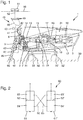
- the nacelle 3 houses a machine carrier 12 which is connected to a tower head slewing ring 7.
- azimuth adjustment motors 9 which align the nacelle 3 or the rotor in the direction of the prevailing wind direction after installation and commissioning, act on the turret slewing ring 7.
- 7 azimuth brakes also engage on the tower head turntable 11, which serve to lock the azimuth setting of the rotor.
- the drive train to be tested begins with a rotor shaft 13 which is rotatably mounted in a rotor bearing 14 designed as a roller bearing.
- the rotor bearing 14 is designed as a fixed bearing that allows only a few millimeters of play in the axial direction of the rotor shaft 13.
- the rotor shaft 13 drives a transmission 15, which converts the slow rotational movement of the rotor shaft into a fast rotational movement of a generator shaft 19, which is shown with clutches, which in turn drives a generator 20 for generating electricity, which is equipped with a heat exchanger 21.
- the transmission 15 also has a rotor brake 17 and a slip ring transmitter 18 and two elastic transmission suspensions or supports 16, one of which is shown in FIG Fig. 1 is shown, while the other is located symmetrically on the other side of the transmission 15 and is therefore covered by the transmission 15.
- the support or the elastic transmission suspension 16 is of conventional design and consists of hollow cylindrical elastomer bodies made of two semi-cylindrical partial bodies which are arranged around a cylindrical bolt. With its cylindrical bearings, the cylinder axis of which is aligned parallel to the rotor shaft 13, the support 16 is a non-locating bearing since, due to its softness in this direction, it absorbs little rotor thrust in the direction of the rotor shaft axis.
- the nacelle 3 is arranged for testing on a bearing frame 31 and is firmly supported against the ground by means of feet 32, 32 'and bolts 33, 33'.
- a drive device 40 according to the invention of a test bench 1 according to the invention rests on a drive flange 5 arranged on the rotor shaft 13. With 6 a pitch cabinet for the blade adjustment is designated, which is attached to the drive flange 5.
- the drive device has a large gear 41, which is seated on the drive flange 5 of the rotor shaft 13. A rotation of the large gear 41 thus also leads to a rotation of the drive train.
- Distributed around the circumference of the large gear 41 are a plurality of pinions 42, ie small gears, the gears of which act on the gears of the large gear 41.
- Each pinion is provided with a motor 43 which drives the pinion 42.
- the motors 43 can be electric or hydraulic. It is in the sectional view in Fig. 1 only two pinions 42 and drive motors 43 are shown, but it will usually be necessary to use a large number of drive motors 43.
- the drive motors require an energy supply, not shown, e.g. B. by means of electrical cables or hydraulic high pressure hoses.
- the claimed feature "freely movable” includes that it is limited by the energy supply, z. B. can come through the cable / hose length. Functionally, however, the drive device 40 can be moved and rotated in all directions with respect to the test specimen.
- the housing or the drive device 40 has a torque support 45 which is seated on the floor 30 with a foot 46 or support foot. This torque support 45 ensures that the torque that is transmitted by the large gear 41 to the drive train in the nacelle 3 is diverted to the floor 30.
- the torque arm also has a cross-feed hydraulic system 60, which prevents radial evasion forced load compensation.
- the drive device 40 also has a holding device 48 at its upper end, in the upper region of which a plurality of holding openings 49 are arranged next to one another.
- the holding openings 49 serve to receive a carrying hook of a lifting device 52, so that the drive device 40 can be held and moved by a trolley 51 on a carrying rail 50 via the lifting device 52.
- the various holding openings 49 are arranged at different positions in the longitudinal direction, so that a specific axial inclination of the drive device 40 is set by selecting a specific holding opening 49. This means that the axis inclination can be adapted to the axis inclination of the drive train in the respective machine house before coupling to a drive train.
- overhead cranes with chains, steel cables or crane slips can be provided.
- trolleys can also be provided with corresponding adjustment devices for height and angle adjustment. This is particularly advantageous if no overhead crane with sufficient load capacity is available.
- Fig. 2 the principle of a cross-feed hydraulic system 60 is shown schematically.
- This comprises two hydraulic cylinders or hydraulic cylinders 61, 61 ', each with a plunger 62, 62', which divides the interior of the hydraulic cylinders 61, 61 'into an upper partial volume 63, 63' and a lower partial volume 64, 64 '.
- the stamps are acted upon from above with the force which, for example, applies the weight force or the respective force which results from a torque from the drive device 40.
- Hydraulic lines 65, 66 are provided between the upper partial volume 63 of the hydraulic cylinder 61 and the lower partial volume 64 'of the hydraulic cylinder 61' on the one hand and the lower partial volume 64 of the hydraulic cylinder 61 and the upper partial volume 63 'of the hydraulic cylinder 61' on the other hand, through which the hydraulic fluid communicates with each other in the sub-volumes connected to each other.
- This cross-feed hydraulic system thus has the effect that radial deflection, which is generated by the torque of the drive device 40, is prevented and the drive device 40 does not move with respect to the drive train.
- the crossover also has the effect that the absorbed sum of forces is zero.
Landscapes
- Engineering & Computer Science (AREA)
- Physics & Mathematics (AREA)
- General Physics & Mathematics (AREA)
- Life Sciences & Earth Sciences (AREA)
- Sustainable Development (AREA)
- Sustainable Energy (AREA)
- Chemical & Material Sciences (AREA)
- Combustion & Propulsion (AREA)
- Mechanical Engineering (AREA)
- General Engineering & Computer Science (AREA)
- Wind Motors (AREA)
Applications Claiming Priority (2)
| Application Number | Priority Date | Filing Date | Title |
|---|---|---|---|
| DE102012212844.1A DE102012212844A1 (de) | 2012-07-23 | 2012-07-23 | Prüfstand und Verfahren zum Prüfen eines Triebstrangs einer Windenergieanlage |
| PCT/EP2013/001960 WO2014015941A1 (de) | 2012-07-23 | 2013-07-04 | Prüfstand und verfahren zum prüfen eines triebstrangs einer windenergieanlage |
Publications (2)
| Publication Number | Publication Date |
|---|---|
| EP2875329A1 EP2875329A1 (de) | 2015-05-27 |
| EP2875329B1 true EP2875329B1 (de) | 2020-04-22 |
Family
ID=48793160
Family Applications (1)
| Application Number | Title | Priority Date | Filing Date |
|---|---|---|---|
| EP13737136.5A Active EP2875329B1 (de) | 2012-07-23 | 2013-07-04 | Prüfstand und verfahren zum prüfen eines triebstrangs einer windenergieanlage |
Country Status (7)
| Country | Link |
|---|---|
| US (1) | US9766158B2 (da) |
| EP (1) | EP2875329B1 (da) |
| CA (1) | CA2879509C (da) |
| DE (1) | DE102012212844A1 (da) |
| DK (1) | DK2875329T3 (da) |
| ES (1) | ES2798778T3 (da) |
| WO (1) | WO2014015941A1 (da) |
Families Citing this family (3)
| Publication number | Priority date | Publication date | Assignee | Title |
|---|---|---|---|---|
| DK178949B1 (en) * | 2016-03-11 | 2017-06-26 | Envision Energy Denmark Aps | Moment bearing test device for testing a moment bearing of a wind turbine and a method thereof |
| DK3264060T3 (da) * | 2016-06-30 | 2019-08-26 | Siemens Gamesa Renewable Energy As | Testrig til en back-to-back-test af en turbine |
| CN109677631A (zh) * | 2018-12-11 | 2019-04-26 | 武汉航空仪表有限责任公司 | 一种主/尾桨集流环地面动态模拟试验装置 |
Citations (1)
| Publication number | Priority date | Publication date | Assignee | Title |
|---|---|---|---|---|
| US20050172729A1 (en) * | 2004-02-10 | 2005-08-11 | Gonzalez Jose Ignacio L. | Test bench for wind turbines |
Family Cites Families (6)
| Publication number | Priority date | Publication date | Assignee | Title |
|---|---|---|---|---|
| US7362225B2 (en) * | 2004-11-24 | 2008-04-22 | Elesys North America Inc. | Flexible occupant sensor and method of use |
| AU2007256566B2 (en) * | 2006-07-03 | 2010-09-09 | Vestas Wind Systems A/S | A test bench comprising angle adjustment means and methods for testing wind turbine equipment |
| EP2035698B1 (en) | 2006-07-03 | 2017-06-14 | Vestas Wind Systems A/S | A test bench and a method for testing wind turbine equipment |
| MX2008016209A (es) | 2006-07-03 | 2009-02-17 | Vestas Wind Sys As | Sistema para probar turbinas eolicas. |
| KR20120048659A (ko) * | 2009-07-31 | 2012-05-15 | 엠티에스 시스템즈 코포레이숀 | 풍력 터빈 구동 트레인 테스트 조립체 |
| DE102010017456B4 (de) * | 2010-06-18 | 2017-01-05 | Industrieanlagen-Betriebsgesellschaft Mbh | Belastungsvorrichtung, Prüfstand mit einer derartigen Belastungsvorrichtung, Prüfanordnung und Prüfverfahren |
-
2012
- 2012-07-23 DE DE102012212844.1A patent/DE102012212844A1/de not_active Ceased
-
2013
- 2013-07-04 CA CA2879509A patent/CA2879509C/en not_active Expired - Fee Related
- 2013-07-04 DK DK13737136.5T patent/DK2875329T3/da active
- 2013-07-04 ES ES13737136T patent/ES2798778T3/es active Active
- 2013-07-04 WO PCT/EP2013/001960 patent/WO2014015941A1/de not_active Ceased
- 2013-07-04 EP EP13737136.5A patent/EP2875329B1/de active Active
-
2015
- 2015-01-22 US US14/602,606 patent/US9766158B2/en active Active
Patent Citations (1)
| Publication number | Priority date | Publication date | Assignee | Title |
|---|---|---|---|---|
| US20050172729A1 (en) * | 2004-02-10 | 2005-08-11 | Gonzalez Jose Ignacio L. | Test bench for wind turbines |
Also Published As
| Publication number | Publication date |
|---|---|
| DE102012212844A1 (de) | 2014-01-23 |
| US20150128726A1 (en) | 2015-05-14 |
| ES2798778T3 (es) | 2020-12-14 |
| CA2879509A1 (en) | 2014-01-30 |
| DK2875329T3 (da) | 2020-07-06 |
| WO2014015941A1 (de) | 2014-01-30 |
| CA2879509C (en) | 2018-02-27 |
| US9766158B2 (en) | 2017-09-19 |
| EP2875329A1 (de) | 2015-05-27 |
Similar Documents
| Publication | Publication Date | Title |
|---|---|---|
| EP2616714B1 (de) | Demontage eines getriebes einer windenergieanlage | |
| DE102010017456B4 (de) | Belastungsvorrichtung, Prüfstand mit einer derartigen Belastungsvorrichtung, Prüfanordnung und Prüfverfahren | |
| EP1659286B1 (de) | Törn-Vorrichtung zum Drehen des Antriebsstranges einer Windkraftanlage | |
| EP2831414B1 (de) | Windenergieanlage mit getriebelagerung und verfahren zum warten der getriebelagerung | |
| DE102008033066B4 (de) | Demontage eines Getriebes einer Windenergieanlage | |
| EP2764237B1 (de) | Verfahren und vorrichtung zum montieren eines rotors einer windenergieanlage | |
| EP2661554B1 (de) | Windenergieanlage | |
| EP2831413B1 (de) | Windenergieanlage mit getriebelagerung und verfahren zum warten der getriebelagerung | |
| EP3121443B1 (de) | Triebstranglagerung einer windenergieanlage und windenergieanlage | |
| DE102012222637A1 (de) | Turnantrieb für eine Windenergieanlage und Verfahren zum Drehen der Rotorwelle einer Windenergieanlage | |
| DE102011017801A1 (de) | Windenergieanlage mit einer Mehrzahl von Verschiebeeinheiten zur Montage oder Demontage von Rotorblättern und Verfahren hierzu | |
| EP4298421B1 (de) | Überlastschutz für antriebsprüfstände | |
| EP2875329B1 (de) | Prüfstand und verfahren zum prüfen eines triebstrangs einer windenergieanlage | |
| EP1277954A2 (de) | Windenergieanlage | |
| DE10307929B4 (de) | Anordnung zur Drehung einer Maschinengondel | |
| WO2022175109A1 (de) | Prüfung von planetengetrieben ohne planetenträgerlagerung | |
| EP3161311B1 (de) | Verfahren zum austausch eines wälzlagers und verfahren zum axialen verschieben eines wka-getriebes | |
| EP3242013A1 (de) | Windenergieanlage mit einer vorrichtung zum drehen einer gondel der windenergieanlage und verfahren zur montage einer vorrichtung zum drehen einer gondel | |
| EP4298420A1 (de) | Zentrale drehmomentabstützung für planetengetriebetests mit drehmomentstütze | |
| DE102017205604B4 (de) | Verfahren zum Prüfen von Großlagern für Windenergieanlagen, Lageranordnung und Prüfstand | |
| DE102010009857A1 (de) | Verfahren zum Abbremsen einer Windenergieanlage und Abbremsvorrichtung zur Durchführung des Verfahrens | |
| EP3502464B1 (de) | Windenergieanlage mit triebstrang | |
| DE102012223191A1 (de) | Mitnahmevorrichtung | |
| DE202015001222U1 (de) | Kranplattform zum Tausch defekter Komponenten wie Getriebe oder Generatoren an Windenergieanlagen ohne mobilen Schwerlastkran | |
| DE102009051457A1 (de) | Rotierende Anlage zur Erzeugung elektrischer Energie |
Legal Events
| Date | Code | Title | Description |
|---|---|---|---|
| PUAI | Public reference made under article 153(3) epc to a published international application that has entered the european phase |
Free format text: ORIGINAL CODE: 0009012 |
|
| 17P | Request for examination filed |
Effective date: 20150107 |
|
| AK | Designated contracting states |
Kind code of ref document: A1 Designated state(s): AL AT BE BG CH CY CZ DE DK EE ES FI FR GB GR HR HU IE IS IT LI LT LU LV MC MK MT NL NO PL PT RO RS SE SI SK SM TR |
|
| AX | Request for extension of the european patent |
Extension state: BA ME |
|
| RAP1 | Party data changed (applicant data changed or rights of an application transferred) |
Owner name: SENVION GMBH |
|
| DAX | Request for extension of the european patent (deleted) | ||
| 17Q | First examination report despatched |
Effective date: 20160304 |
|
| STAA | Information on the status of an ep patent application or granted ep patent |
Free format text: STATUS: EXAMINATION IS IN PROGRESS |
|
| REG | Reference to a national code |
Ref country code: DE Ref legal event code: R079 Ref document number: 502013014623 Country of ref document: DE Free format text: PREVIOUS MAIN CLASS: G01M0013020000 Ipc: G01M0013027000 |
|
| GRAP | Despatch of communication of intention to grant a patent |
Free format text: ORIGINAL CODE: EPIDOSNIGR1 |
|
| STAA | Information on the status of an ep patent application or granted ep patent |
Free format text: STATUS: GRANT OF PATENT IS INTENDED |
|
| RIC1 | Information provided on ipc code assigned before grant |
Ipc: G01M 13/027 20190101AFI20190903BHEP Ipc: F03D 17/00 20160101ALI20190903BHEP |
|
| INTG | Intention to grant announced |
Effective date: 20190924 |
|
| GRAS | Grant fee paid |
Free format text: ORIGINAL CODE: EPIDOSNIGR3 |
|
| GRAA | (expected) grant |
Free format text: ORIGINAL CODE: 0009210 |
|
| STAA | Information on the status of an ep patent application or granted ep patent |
Free format text: STATUS: THE PATENT HAS BEEN GRANTED |
|
| AK | Designated contracting states |
Kind code of ref document: B1 Designated state(s): AL AT BE BG CH CY CZ DE DK EE ES FI FR GB GR HR HU IE IS IT LI LT LU LV MC MK MT NL NO PL PT RO RS SE SI SK SM TR |
|
| RAP1 | Party data changed (applicant data changed or rights of an application transferred) |
Owner name: SENVION DEUTSCHLAND GMBH |
|
| REG | Reference to a national code |
Ref country code: GB Ref legal event code: FG4D Free format text: NOT ENGLISH |
|
| REG | Reference to a national code |
Ref country code: CH Ref legal event code: EP |
|
| REG | Reference to a national code |
Ref country code: DE Ref legal event code: R096 Ref document number: 502013014623 Country of ref document: DE |
|
| REG | Reference to a national code |
Ref country code: IE Ref legal event code: FG4D Free format text: LANGUAGE OF EP DOCUMENT: GERMAN |
|
| REG | Reference to a national code |
Ref country code: AT Ref legal event code: REF Ref document number: 1260760 Country of ref document: AT Kind code of ref document: T Effective date: 20200515 |
|
| REG | Reference to a national code |
Ref country code: DK Ref legal event code: T3 Effective date: 20200630 |
|
| REG | Reference to a national code |
Ref country code: LT Ref legal event code: MG4D |
|
| REG | Reference to a national code |
Ref country code: NL Ref legal event code: MP Effective date: 20200422 |
|
| PG25 | Lapsed in a contracting state [announced via postgrant information from national office to epo] |
Ref country code: IS Free format text: LAPSE BECAUSE OF FAILURE TO SUBMIT A TRANSLATION OF THE DESCRIPTION OR TO PAY THE FEE WITHIN THE PRESCRIBED TIME-LIMIT Effective date: 20200822 Ref country code: FI Free format text: LAPSE BECAUSE OF FAILURE TO SUBMIT A TRANSLATION OF THE DESCRIPTION OR TO PAY THE FEE WITHIN THE PRESCRIBED TIME-LIMIT Effective date: 20200422 Ref country code: NO Free format text: LAPSE BECAUSE OF FAILURE TO SUBMIT A TRANSLATION OF THE DESCRIPTION OR TO PAY THE FEE WITHIN THE PRESCRIBED TIME-LIMIT Effective date: 20200722 Ref country code: SE Free format text: LAPSE BECAUSE OF FAILURE TO SUBMIT A TRANSLATION OF THE DESCRIPTION OR TO PAY THE FEE WITHIN THE PRESCRIBED TIME-LIMIT Effective date: 20200422 Ref country code: NL Free format text: LAPSE BECAUSE OF FAILURE TO SUBMIT A TRANSLATION OF THE DESCRIPTION OR TO PAY THE FEE WITHIN THE PRESCRIBED TIME-LIMIT Effective date: 20200422 Ref country code: GR Free format text: LAPSE BECAUSE OF FAILURE TO SUBMIT A TRANSLATION OF THE DESCRIPTION OR TO PAY THE FEE WITHIN THE PRESCRIBED TIME-LIMIT Effective date: 20200723 Ref country code: LT Free format text: LAPSE BECAUSE OF FAILURE TO SUBMIT A TRANSLATION OF THE DESCRIPTION OR TO PAY THE FEE WITHIN THE PRESCRIBED TIME-LIMIT Effective date: 20200422 Ref country code: PT Free format text: LAPSE BECAUSE OF FAILURE TO SUBMIT A TRANSLATION OF THE DESCRIPTION OR TO PAY THE FEE WITHIN THE PRESCRIBED TIME-LIMIT Effective date: 20200824 |
|
| PGFP | Annual fee paid to national office [announced via postgrant information from national office to epo] |
Ref country code: ES Payment date: 20200818 Year of fee payment: 8 |
|
| PG25 | Lapsed in a contracting state [announced via postgrant information from national office to epo] |
Ref country code: LV Free format text: LAPSE BECAUSE OF FAILURE TO SUBMIT A TRANSLATION OF THE DESCRIPTION OR TO PAY THE FEE WITHIN THE PRESCRIBED TIME-LIMIT Effective date: 20200422 Ref country code: BG Free format text: LAPSE BECAUSE OF FAILURE TO SUBMIT A TRANSLATION OF THE DESCRIPTION OR TO PAY THE FEE WITHIN THE PRESCRIBED TIME-LIMIT Effective date: 20200722 Ref country code: RS Free format text: LAPSE BECAUSE OF FAILURE TO SUBMIT A TRANSLATION OF THE DESCRIPTION OR TO PAY THE FEE WITHIN THE PRESCRIBED TIME-LIMIT Effective date: 20200422 Ref country code: HR Free format text: LAPSE BECAUSE OF FAILURE TO SUBMIT A TRANSLATION OF THE DESCRIPTION OR TO PAY THE FEE WITHIN THE PRESCRIBED TIME-LIMIT Effective date: 20200422 |
|
| REG | Reference to a national code |
Ref country code: ES Ref legal event code: FG2A Ref document number: 2798778 Country of ref document: ES Kind code of ref document: T3 Effective date: 20201214 |
|
| PG25 | Lapsed in a contracting state [announced via postgrant information from national office to epo] |
Ref country code: AL Free format text: LAPSE BECAUSE OF FAILURE TO SUBMIT A TRANSLATION OF THE DESCRIPTION OR TO PAY THE FEE WITHIN THE PRESCRIBED TIME-LIMIT Effective date: 20200422 |
|
| REG | Reference to a national code |
Ref country code: DE Ref legal event code: R097 Ref document number: 502013014623 Country of ref document: DE |
|
| PG25 | Lapsed in a contracting state [announced via postgrant information from national office to epo] |
Ref country code: IT Free format text: LAPSE BECAUSE OF FAILURE TO SUBMIT A TRANSLATION OF THE DESCRIPTION OR TO PAY THE FEE WITHIN THE PRESCRIBED TIME-LIMIT Effective date: 20200422 Ref country code: EE Free format text: LAPSE BECAUSE OF FAILURE TO SUBMIT A TRANSLATION OF THE DESCRIPTION OR TO PAY THE FEE WITHIN THE PRESCRIBED TIME-LIMIT Effective date: 20200422 Ref country code: SM Free format text: LAPSE BECAUSE OF FAILURE TO SUBMIT A TRANSLATION OF THE DESCRIPTION OR TO PAY THE FEE WITHIN THE PRESCRIBED TIME-LIMIT Effective date: 20200422 Ref country code: CZ Free format text: LAPSE BECAUSE OF FAILURE TO SUBMIT A TRANSLATION OF THE DESCRIPTION OR TO PAY THE FEE WITHIN THE PRESCRIBED TIME-LIMIT Effective date: 20200422 Ref country code: RO Free format text: LAPSE BECAUSE OF FAILURE TO SUBMIT A TRANSLATION OF THE DESCRIPTION OR TO PAY THE FEE WITHIN THE PRESCRIBED TIME-LIMIT Effective date: 20200422 |
|
| PG25 | Lapsed in a contracting state [announced via postgrant information from national office to epo] |
Ref country code: PL Free format text: LAPSE BECAUSE OF FAILURE TO SUBMIT A TRANSLATION OF THE DESCRIPTION OR TO PAY THE FEE WITHIN THE PRESCRIBED TIME-LIMIT Effective date: 20200422 Ref country code: SK Free format text: LAPSE BECAUSE OF FAILURE TO SUBMIT A TRANSLATION OF THE DESCRIPTION OR TO PAY THE FEE WITHIN THE PRESCRIBED TIME-LIMIT Effective date: 20200422 Ref country code: MC Free format text: LAPSE BECAUSE OF FAILURE TO SUBMIT A TRANSLATION OF THE DESCRIPTION OR TO PAY THE FEE WITHIN THE PRESCRIBED TIME-LIMIT Effective date: 20200422 |
|
| PLBE | No opposition filed within time limit |
Free format text: ORIGINAL CODE: 0009261 |
|
| REG | Reference to a national code |
Ref country code: CH Ref legal event code: PL |
|
| STAA | Information on the status of an ep patent application or granted ep patent |
Free format text: STATUS: NO OPPOSITION FILED WITHIN TIME LIMIT |
|
| 26N | No opposition filed |
Effective date: 20210125 |
|
| REG | Reference to a national code |
Ref country code: BE Ref legal event code: MM Effective date: 20200731 |
|
| PG25 | Lapsed in a contracting state [announced via postgrant information from national office to epo] |
Ref country code: IE Free format text: LAPSE BECAUSE OF NON-PAYMENT OF DUE FEES Effective date: 20200704 Ref country code: LI Free format text: LAPSE BECAUSE OF NON-PAYMENT OF DUE FEES Effective date: 20200731 Ref country code: CH Free format text: LAPSE BECAUSE OF NON-PAYMENT OF DUE FEES Effective date: 20200731 Ref country code: LU Free format text: LAPSE BECAUSE OF NON-PAYMENT OF DUE FEES Effective date: 20200704 |
|
| PG25 | Lapsed in a contracting state [announced via postgrant information from national office to epo] |
Ref country code: BE Free format text: LAPSE BECAUSE OF NON-PAYMENT OF DUE FEES Effective date: 20200731 Ref country code: SI Free format text: LAPSE BECAUSE OF FAILURE TO SUBMIT A TRANSLATION OF THE DESCRIPTION OR TO PAY THE FEE WITHIN THE PRESCRIBED TIME-LIMIT Effective date: 20200422 |
|
| REG | Reference to a national code |
Ref country code: AT Ref legal event code: MM01 Ref document number: 1260760 Country of ref document: AT Kind code of ref document: T Effective date: 20200704 |
|
| PG25 | Lapsed in a contracting state [announced via postgrant information from national office to epo] |
Ref country code: AT Free format text: LAPSE BECAUSE OF NON-PAYMENT OF DUE FEES Effective date: 20200704 |
|
| PG25 | Lapsed in a contracting state [announced via postgrant information from national office to epo] |
Ref country code: TR Free format text: LAPSE BECAUSE OF FAILURE TO SUBMIT A TRANSLATION OF THE DESCRIPTION OR TO PAY THE FEE WITHIN THE PRESCRIBED TIME-LIMIT Effective date: 20200422 Ref country code: MT Free format text: LAPSE BECAUSE OF FAILURE TO SUBMIT A TRANSLATION OF THE DESCRIPTION OR TO PAY THE FEE WITHIN THE PRESCRIBED TIME-LIMIT Effective date: 20200422 Ref country code: CY Free format text: LAPSE BECAUSE OF FAILURE TO SUBMIT A TRANSLATION OF THE DESCRIPTION OR TO PAY THE FEE WITHIN THE PRESCRIBED TIME-LIMIT Effective date: 20200422 |
|
| PG25 | Lapsed in a contracting state [announced via postgrant information from national office to epo] |
Ref country code: MK Free format text: LAPSE BECAUSE OF FAILURE TO SUBMIT A TRANSLATION OF THE DESCRIPTION OR TO PAY THE FEE WITHIN THE PRESCRIBED TIME-LIMIT Effective date: 20200422 |
|
| REG | Reference to a national code |
Ref country code: ES Ref legal event code: FD2A Effective date: 20220930 |
|
| REG | Reference to a national code |
Ref country code: DE Ref legal event code: R081 Ref document number: 502013014623 Country of ref document: DE Owner name: SIEMENS GAMESA RENEWABLE ENERGY SERVICE GMBH, DE Free format text: FORMER OWNER: SENVION DEUTSCHLAND GMBH, 22297 HAMBURG, DE |
|
| PG25 | Lapsed in a contracting state [announced via postgrant information from national office to epo] |
Ref country code: ES Free format text: LAPSE BECAUSE OF NON-PAYMENT OF DUE FEES Effective date: 20210705 |
|
| PGFP | Annual fee paid to national office [announced via postgrant information from national office to epo] |
Ref country code: DK Payment date: 20250725 Year of fee payment: 13 Ref country code: DE Payment date: 20250728 Year of fee payment: 13 |
|
| PGFP | Annual fee paid to national office [announced via postgrant information from national office to epo] |
Ref country code: GB Payment date: 20250722 Year of fee payment: 13 |
|
| PGFP | Annual fee paid to national office [announced via postgrant information from national office to epo] |
Ref country code: FR Payment date: 20250725 Year of fee payment: 13 |