EP2875923B1 - Machine d'usinage pour parois, en particulier pour des parois en bois ou parois multicouche et analogues - Google Patents
Machine d'usinage pour parois, en particulier pour des parois en bois ou parois multicouche et analogues Download PDFInfo
- Publication number
- EP2875923B1 EP2875923B1 EP14191290.7A EP14191290A EP2875923B1 EP 2875923 B1 EP2875923 B1 EP 2875923B1 EP 14191290 A EP14191290 A EP 14191290A EP 2875923 B1 EP2875923 B1 EP 2875923B1
- Authority
- EP
- European Patent Office
- Prior art keywords
- frame
- walls
- machine according
- translation
- movement
- Prior art date
- Legal status (The legal status is an assumption and is not a legal conclusion. Google has not performed a legal analysis and makes no representation as to the accuracy of the status listed.)
- Active
Links
Images



Classifications
-
- B—PERFORMING OPERATIONS; TRANSPORTING
- B27—WORKING OR PRESERVING WOOD OR SIMILAR MATERIAL; NAILING OR STAPLING MACHINES IN GENERAL
- B27M—WORKING OF WOOD NOT PROVIDED FOR IN SUBCLASSES B27B - B27L; MANUFACTURE OF SPECIFIC WOODEN ARTICLES
- B27M1/00—Working of wood not provided for in subclasses B27B - B27L, e.g. by stretching
- B27M1/08—Working of wood not provided for in subclasses B27B - B27L, e.g. by stretching by multi-step processes
-
- B—PERFORMING OPERATIONS; TRANSPORTING
- B23—MACHINE TOOLS; METAL-WORKING NOT OTHERWISE PROVIDED FOR
- B23Q—DETAILS, COMPONENTS, OR ACCESSORIES FOR MACHINE TOOLS, e.g. ARRANGEMENTS FOR COPYING OR CONTROLLING; MACHINE TOOLS IN GENERAL CHARACTERISED BY THE CONSTRUCTION OF PARTICULAR DETAILS OR COMPONENTS; COMBINATIONS OR ASSOCIATIONS OF METAL-WORKING MACHINES, NOT DIRECTED TO A PARTICULAR RESULT
- B23Q3/00—Devices holding, supporting, or positioning work or tools, of a kind normally removable from the machine
- B23Q3/02—Devices holding, supporting, or positioning work or tools, of a kind normally removable from the machine for mounting on a work-table, tool-slide, or analogous part
- B23Q3/04—Devices holding, supporting, or positioning work or tools, of a kind normally removable from the machine for mounting on a work-table, tool-slide, or analogous part adjustable in inclination
-
- B—PERFORMING OPERATIONS; TRANSPORTING
- B27—WORKING OR PRESERVING WOOD OR SIMILAR MATERIAL; NAILING OR STAPLING MACHINES IN GENERAL
- B27B—SAWS FOR WOOD OR SIMILAR MATERIAL; COMPONENTS OR ACCESSORIES THEREFOR
- B27B27/00—Guide fences or stops for timber in saw mills or sawing machines; Measuring equipment thereon
- B27B27/10—Devices for moving or adjusting the guide fences or stops
-
- B—PERFORMING OPERATIONS; TRANSPORTING
- B27—WORKING OR PRESERVING WOOD OR SIMILAR MATERIAL; NAILING OR STAPLING MACHINES IN GENERAL
- B27M—WORKING OF WOOD NOT PROVIDED FOR IN SUBCLASSES B27B - B27L; MANUFACTURE OF SPECIFIC WOODEN ARTICLES
- B27M3/00—Manufacture or reconditioning of specific semi-finished or finished articles
-
- B—PERFORMING OPERATIONS; TRANSPORTING
- B27—WORKING OR PRESERVING WOOD OR SIMILAR MATERIAL; NAILING OR STAPLING MACHINES IN GENERAL
- B27M—WORKING OF WOOD NOT PROVIDED FOR IN SUBCLASSES B27B - B27L; MANUFACTURE OF SPECIFIC WOODEN ARTICLES
- B27M3/00—Manufacture or reconditioning of specific semi-finished or finished articles
- B27M3/0013—Manufacture or reconditioning of specific semi-finished or finished articles of composite or compound articles
- B27M3/0073—Manufacture or reconditioning of specific semi-finished or finished articles of composite or compound articles characterised by nailing, stapling or screwing connections
Definitions
- the present invention relates to a machine for machining walls according to the preamble of claim 1.
- a machine is known from document FR 2 892 960 .
- mobile portal machines which are equipped with a milling head with "five axes", i.e. they comprise a portal that can perform a translational motion along a first axis X, longitudinal and parallel to the working surface, with a tool-holder carriage that performs a translational motion along a second axis Y which is transverse to the first axis X, and a further carriage that can perform a translational motion along a third axis Z, vertical, which supports a bi-rotary head, rotateable about two axes, which in turn comprises an electric spindle for holding a milling cutter; the electric spindle is associated with an automatic tool-changing device.
- Such a mobile portal is arranged so as to slide on adapted sliding guides with respect to a working surface.
- the working surface can be used to support, for example, preassembled walls, or a wall can be assembled on it, known as a frame wall, which is constituted by a first layer which is a panel of OSB (Oriented Strand Board), a second layer of beams, and a third layer of OSB.
- OSB Oriented Strand Board
- a first carriage moves transversely and serves exclusively to perform the turning over
- a second carriage moves longitudinally, carries the panel being machined below the portal carrying the milling or cutting heads, and finally is arranged in place of the first carriage, which moves to one side, and the turning over of the panel begins by way of the rotation of the resting surfaces of the carriages to face each other in order to execute the passage, with turning over of the panel, from one carriage to the other.
- Such first and second carriages each move on corresponding guide rails that are cheaply made with drawn iron plates, which result in a sliding with scant precision, with low speeds and acceleration owing to the slipping of the wheels of the carriages on the iron plates that define the guide rails.
- the aim of the present invention is to provide a machine for machining walls, particularly for walls made of wood or multilayer walls and the like, which is capable of overcoming the limitations of conventional machines for machining walls.
- an object of the invention is to devise a machine for machining walls with no auxiliary lateral carriages for the overturning of a wall being machined.
- Another object of the invention is to devise a machine that is more compact overall, it being possible to do without the lateral encumbrances of auxiliary carriages for turning over the wall being machined.
- Another object of the invention is thus to devise a machine for machining walls which is faster and more precise with respect to conventional machines.
- a machine for machining walls particularly for walls made of wood or multilayer walls and the like, comprising a portal with one or more working heads, and a working surface for resting a wall to be machined, said portal and said working surface being configured for the movement of one with respect to the other, said machine for machining walls being characterized in that said working surface comprises a first and second opposite support and movement frames, both provided with means for translation and rotation with respect to a fixed base frame and configured so as to allow each support and movement frame to provide the following configurations:
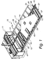
- a machine for machining walls particularly for walls made of wood or multilayer walls and the like, according to the invention, is generally designated with the reference numeral 10.
- the machine 10 comprises a portal 11, with one or more working heads 12, and a working surface 13 for resting a wall to be machined 14.
- the portal 11 and the working surface 13 are configured for the movement of one with respect to the other, for example, but not exclusively, the portal 11 is of the mobile type, i.e. it is configured to slide on guide rails 15 and 16.
- the machine 10 for machining walls has the peculiarity that the working surface 13 comprises a first and second opposite support and movement frames 17 and 18, both provided with means for translation and rotation, 19 and 20 respectively, with respect to a base frame 21, which is fixed to the ground.
- the translation and rotation means, 19 and 20, better described hereinbelow, are configured so as to allow each support and movement frame 17 and 18 to provide the following configurations:
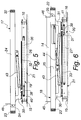
- Each of the two frames 17 and 18 is substantially comb-shaped, with a longitudinal bar 22 and 23 respectively, and a plurality of crossmembers 24 and 25, which are fixed at right angles to the respective longitudinal bar.
- the two frames 17 and 18 are arranged so that longitudinally, one encounters a crossmember 24 of a first frame 17 and a crossmember 25 of the second frame 18 alternately.
- each frame 17 and 18 at least two translation and rotation units, which are applied to respective spaced crossmembers of the corresponding frame.
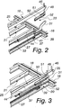
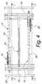
- the translation and rotation means 19 and 20 are interposed between a crossmember, for example a crossmember 25 of the second frame 18 in Figures 2 and 3 , and a corresponding underlying crossmember 26 and 27 of the base frame 21.
- the translation and rotation means 19 and 20 comprise a slider 30 and 31 that is arranged so as to slide on a guide 32 and 33 that is arranged above the corresponding crossmember 26 or 27 of the base frame 21; the corresponding crossmember 24 and 25 of the support and movement frame 17 and 18 is pivoted, with fulcrum 34 and 35, to the slider 30 and 31.
- the linear guide system 32 and 33 and the fulcrum of rotation 34 and 35 are present on all the crossmembers 24 and 25 of the two frames 17 and 18, while the translation and rotation means 19 and 20 are present only at a limited number of crossmembers, for example two crossmembers for each frame 17 and 18.
- the slider 30 and 31 is moved with respect to its guide 32 and 33 by way of pusher or traction means, for example by way of a chain transmission 36 and 37, such chain 36 and 37 being coupled to the slider 30 and 31 by way of a bracket 38 and 39.
- the chain 36 and 37 is actuated by a pinion 40 and 41 that is keyed on a driving shaft that is extended longitudinally to the direction of extension of the working surface 13 and actuates simultaneously all the chains 36 and 37 related to a same frame 17 and 18 by way of corresponding pinions.
- the movement of the slider 30 and 31, by way of the motion of the chains, is provided by a gear motor, which is not shown for the sake of simplicity and should be understood as being of conventional type, which actuates the driving shaft on which are keyed the pinions that entrain the chain on which the bracket 38 and 39 respectively is fixed.
- a linear actuator of the cylinder/piston type, or other, electric linear actuator, which should be understood as being of known type, can be used.
- the translation and rotation means 19 and 20 comprise, for the provision of the rotation, a linear actuator 43 and 44 that is interposed between the slider 30 and 31 and the corresponding crossmember of the support frame 24 and 25.
- the linear actuator 43 and 44 is constituted by a fluid-operated actuation cylinder, hydraulic or pneumatic, or by an actuator with electric motorization, or by another, equivalent linear actuator.
- the wall 14 being machined is kept in position on the frames 17 and 18 by way of fixed abutments 45 and 46, which are fixed at the ends respectively of the crossmembers 24 and 25 of the two frames 17 and 18, and movable abutments 47 and 48.
- the movable abutments for example 48 in Figures 2 and 3 , are supported by a slider 50 that is adapted to slide on a guide 51 that is fixed to the crossmember 25 of the second frame 18, and similarly to a crossmember 24 of the first frame 17; the slider is moved by a linear actuator 52, which is embodied for example in a fluid-operated actuation cylinder/piston.
- the abutments both fixed and mobile, are preferably retractable, i.e. they can be actuated in translational movement along their axis so as to retract below the resting surface of the corresponding crossmember with which they are associated.
- Operation of the machine 10 according to the invention is the following.
- a first step which is governed by an electronic control unit that manages and coordinates the sequence of steps using the various movement motors for translational motion chains 36 and 37 and linear actuators for rotation 43 and 44, the two frames 17 and 18 retreat laterally outwardly with respect to the base frame 21 as in Figure 8 , with the wall, resting on the abutments, for example the fixed abutments 45, remaining on the first frame 17.
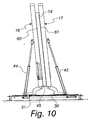
- the configuration in Figure 10 is when the passage occurs of the wall 14 from the first frame 17 to the second frame 18, with the wall 14 that rests downwardly on the abutments 45 and 46 both of the first frame 17 and of the second frame 18, and with the first side 60 of the wall 14 resting on the second frame 18.
- Figure 11 shows an example of a configuration of descent of the two frames 17 and 18 with the wall 14 now carried, turned over, by the second frame 18, thus with the second side 61 of the wall 14 directed upwardly and available for machining after the descent.
- the portal 11 can be of known type, for example a mobile portal with a milling head with "five axes", i.e. comprising a portal that can perform a translational motion along a first axis X, longitudinal and parallel to the working surface, with a tool-holder carriage that performs a translational motion along a second axis Y which is transverse to the first axis X, and a further carriage that can perform a translational motion along a third axis Z, vertical, which supports a bi-rotary head, rotateable about two axes, which in turn comprises an electric spindle for holding a milling cutter; the electric spindle is associated with an automatic tool-changing device.
- a mobile portal with a milling head with "five axes” i.e. comprising a portal that can perform a translational motion along a first axis X, longitudinal and parallel to the working surface, with a tool-holder carriage that performs a translational motion along a second axis Y which
- a machine for machining walls has been devised with no auxiliary lateral carriages for the overturning of a wall being machined, thanks to the presence of the two opposite frames 17 and 18 and of the corresponding translation and rotation means 19 and 20 which make possible the described movement thereof.
Landscapes
- Engineering & Computer Science (AREA)
- Life Sciences & Earth Sciences (AREA)
- Wood Science & Technology (AREA)
- Forests & Forestry (AREA)
- Mechanical Engineering (AREA)
- Manufacturing & Machinery (AREA)
- Machine Tool Units (AREA)
- Load-Bearing And Curtain Walls (AREA)
Claims (10)
- Machine (10) d'usinage pour parois, en particulier pour des parois en bois ou des parois multicouches et analogues, comprenant une entrée (11) munie d'une ou plusieurs tête(s) de travail (12) et une surface de travail (13) qui doit recevoir une paroi (14) à usiner, ladite entrée (11) et ladite surface de travail (13) étant configurées pour permettre le mouvement de l'une par rapport à l'autre, ladite machine d'usinage pour parois étant caractérisée en ce que ladite surface de travail (13) comprend un premier et un second cadre de support et de mouvement (17, 18) opposés, les deux cadres étant munis de moyens de translation et de rotation (19, 20) par rapport à un cadre de base (21) fixe et configurés pour permettre à chaque cadre de support et de mouvement (17, 18) de prendre les configurations suivantes :- une configuration abaissée sensiblement horizontale permettant d'usiner une paroi (14),- une configuration inclinée qui fait face à l'autre cadre de support et de mouvement (17, 18) opposé afin de retourner une paroi (14) supportée par ledit premier cadre de support et de mouvement (17) sur ledit second cadre de support et de mouvement (18).
- Machine selon la revendication 1, caractérisée en ce que chacun des deux cadres (17, 18) a sensiblement la forme d'un peigne, avec une barre longitudinale (22, 23) et une pluralité de traverses (24, 25) qui sont fixées à angle droit par rapport à la barre longitudinale respective.
- Machine selon une ou plusieurs des revendications précédentes, caractérisée en ce que lesdits moyens de translation et de rotation (19, 20) fournissent, pour chaque cadre (17, 18) au moins deux unités de translation et de rotation, qui sont appliquées sur les traverses espacées respectives du cadre correspondant.
- Machine selon une ou plusieurs des revendications précédentes, caractérisée en ce que lesdits moyens de translation et de rotation (19, 20) sont intercalés entre une traverse (24, 25) du cadre (17, 18) correspondant et une traverse (26, 27) sous-jacente du cadre de base (21).
- Machine selon une ou plusieurs des revendications précédentes, caractérisée en ce que lesdits moyens de translation et de rotation (19, 20) comprennent un coulisseau (30, 31) qui est agencé de manière à coulisser sur un guide (32, 33) agencé au-dessus de la traverse (26, 27) correspondante du cadre de base (21), la traverse (24, 25) correspondante du cadre de support et de mouvement (17, 18) étant pivotée jusqu'au coulisseau (30, 31).
- Machine selon les revendications précédentes, caractérisée en ce que ledit coulisseau (30, 31) se déplace par rapport à son guide (32, 33) grâce à des moyens de poussée ou de traction.
- Machine selon une ou plusieurs des revendications précédentes, caractérisée en ce que lesdits moyens de poussée ou de traction sont prévus sous la forme d'une chaine de transmission (36, 37), ladite chaine (36, 37) étant couplée au coulisseau (30, 31) par l'intermédiaire d'une équerre (38, 39).
- Machine selon une ou plusieurs des revendications précédentes, caractérisée en ce que ladite chaine (36, 37) est actionnée par un pignon (40, 41) qui est claveté sur un arbre d'entrainement qui s'étend longitudinalement par rapport à la direction d'extension de la surface de travail (13) et actionne simultanément toutes les chaines (36, 37) liées au même cadre (17, 18) grâce à des pignons correspondants.
- Machine selon une ou plusieurs des revendications précédentes, caractérisée en ce que lesdits moyens de translation et de rotation (19, 20) comprennent, pour assurer la rotation, un actionneur linéaire (43, 44) qui est intercalé entre le coulisseau (30, 31) et la traverse correspondante du cadre de support (24, 25).
- Machine selon une ou plusieurs des revendications précédentes, caractérisée en ce que ladite paroi (14) en cours d'usinage est maintenue en position sur les cadres (17, 18) grâce à des butées fixes (45, 46), qui sont fixées respectivement sur les extrémités des traverses (24, 25) des deux cadres (17, 18), et à des butées mobiles (47, 48).
Applications Claiming Priority (1)
| Application Number | Priority Date | Filing Date | Title |
|---|---|---|---|
| IT000316A ITPD20130316A1 (it) | 2013-11-20 | 2013-11-20 | Macchina per la lavorazione di pareti, in particolare per pareti in legno o pareti multistrato e simili |
Publications (2)
| Publication Number | Publication Date |
|---|---|
| EP2875923A1 EP2875923A1 (fr) | 2015-05-27 |
| EP2875923B1 true EP2875923B1 (fr) | 2016-08-17 |
Family
ID=49958596
Family Applications (1)
| Application Number | Title | Priority Date | Filing Date |
|---|---|---|---|
| EP14191290.7A Active EP2875923B1 (fr) | 2013-11-20 | 2014-10-31 | Machine d'usinage pour parois, en particulier pour des parois en bois ou parois multicouche et analogues |
Country Status (3)
| Country | Link |
|---|---|
| EP (1) | EP2875923B1 (fr) |
| DE (1) | DE202014010665U1 (fr) |
| IT (1) | ITPD20130316A1 (fr) |
Families Citing this family (10)
| Publication number | Priority date | Publication date | Assignee | Title |
|---|---|---|---|---|
| ITPD20130316A1 (it) | 2013-11-20 | 2015-05-21 | Essetre Holding Spa | Macchina per la lavorazione di pareti, in particolare per pareti in legno o pareti multistrato e simili |
| CN105151736A (zh) * | 2015-08-12 | 2015-12-16 | 文登蓝岛建筑工程有限公司 | 墙板自翻转装置 |
| IT201600120284A1 (it) * | 2016-11-28 | 2018-05-28 | Scm Group Spa | Impianto di lavorazione di pannelli e simili e linea di produzione realizzata con tale impianto. |
| IT201800002189A1 (it) * | 2018-01-30 | 2019-07-30 | Mecal S R L | Apparato per il serraggio di un pezzo da lavorare. |
| IT201900006620A1 (it) * | 2019-05-08 | 2020-11-08 | Scm Group Spa | Centro di lavoro di pezzi in legno provvisto di un piano di lavoro intercambiabile. |
| SE545899C2 (en) * | 2023-01-24 | 2024-03-05 | CC100 i Sunne AB | Apparatus and method for producing wall elements and building walls |
| IT202300003684A1 (it) | 2023-03-01 | 2024-09-01 | Essetre S R L Unipersonale | Macchina per la lavorazione di pareti, in particolare per pareti in legno o simili |
| US20240308055A1 (en) * | 2023-03-16 | 2024-09-19 | Illinois Tool Works Inc. | Truss assembly table with truss ejection mechanisms |
| CN117444668B (zh) * | 2023-11-17 | 2024-06-04 | 升励五金(深圳)有限公司 | 一体式下管马达座加工设备 |
| FI20245760A1 (fi) * | 2024-06-13 | 2025-12-14 | Finnish Timber Tech Oy | Menetelmä ja laitteisto ristikkorakenteiden valmistamiseksi |
Family Cites Families (4)
| Publication number | Priority date | Publication date | Assignee | Title |
|---|---|---|---|---|
| DE3925469A1 (de) * | 1989-08-01 | 1991-02-07 | Ludwig Andrae | Einrichtung zum herstellen von stabfoermigen holzbauelementen |
| US6553653B2 (en) * | 2000-06-23 | 2003-04-29 | Billco Manufacturing, Inc. | Vertical assembly table |
| FR2892960A1 (fr) * | 2006-12-08 | 2007-05-11 | Mori Seiki Seisakusho Kk | Machine-outil |
| ITPD20130316A1 (it) | 2013-11-20 | 2015-05-21 | Essetre Holding Spa | Macchina per la lavorazione di pareti, in particolare per pareti in legno o pareti multistrato e simili |
-
2013
- 2013-11-20 IT IT000316A patent/ITPD20130316A1/it unknown
-
2014
- 2014-10-31 DE DE202014010665.7U patent/DE202014010665U1/de not_active Expired - Lifetime
- 2014-10-31 EP EP14191290.7A patent/EP2875923B1/fr active Active
Also Published As
| Publication number | Publication date |
|---|---|
| ITPD20130316A1 (it) | 2015-05-21 |
| EP2875923A1 (fr) | 2015-05-27 |
| DE202014010665U1 (de) | 2016-04-04 |
Similar Documents
| Publication | Publication Date | Title |
|---|---|---|
| EP2875923A1 (fr) | Machine d'usinage pour parois, en particulier pour des parois en bois ou parois multicouche et analogues | |
| EP2983879B1 (fr) | Machine-outil multi-axiale pour le travail de dalles et/ou blocks de pierres | |
| EP2911848B1 (fr) | Machine à outils multiples pour le traitement de produits constitués de matériaux pierreux | |
| EP2138264A1 (fr) | Dispositif de positionnement secondaire pour usinage de pièce de travail | |
| EP2998088B1 (fr) | Centre d'usinage pour dalles en pierre, marbre, matériau synthétique ou similaire avec plan de travail sacrificiel | |
| RU2447988C2 (ru) | Фрезерный станок для механической обработки деревянных балок | |
| EP3049205B1 (fr) | Machine pour la coupe de panneaux, en particulier de marbre, granite, verre et matériaux composites | |
| EP2145744A1 (fr) | Dispositif et procédé pour découper des planches. | |
| RU2018127742A (ru) | Центр для механообработки блоков из экструдированного и вспененного материала с чпу | |
| CN203566802U (zh) | 悬臂式木材复合加工中心 | |
| CN102390058A (zh) | 一种环竖刀异型海绵切割机 | |
| IT9012457A1 (it) | Macchina combinata per la realizzazione automatica di lavorazioni di sezionatura , di fresatura, di fresatura e taglio, di foratura, di fresatura e foratura, di foratura e taglio, di levigatura e/od altre su pannelli o pacchi di pannelli di legno e/o | |
| US20130149055A1 (en) | Machine tool | |
| WO2006057024A1 (fr) | Poste de travail pour la decoupe optimisee de materiaux sous la forme de dalles | |
| CN1701915B (zh) | 加工工件的机械用的进给装置及这种工件的加工方法 | |
| CN108247775A (zh) | 木工榫头数控加工机床 | |
| EP1974880B1 (fr) | Dispositif de coupe de pièces usinées | |
| US20010029160A1 (en) | Double moving column grinder with simultaneous two wheel grinding | |
| CN105479603A (zh) | 一种陶粒块自动切割线 | |
| EP2075104A2 (fr) | Machine de collage des bords d'une pièce en forme de plaque avec un dispositif d'usinage de bords | |
| CN202784697U (zh) | 搬运机具 | |
| KR20190003616A (ko) | 윈도우 프로파일 또는 도어 프로파일과 같은 로드 형상 피가공물을 기계가공하기 위한 장치 | |
| EP1749624A1 (fr) | Un dispositif avec des chariots de transport pour charger et décharger des pièces dans un dispositif de coupe à jet d'eau. | |
| KR101008079B1 (ko) | 서보 톰슨 프레스의 이송 테이블 | |
| EP3038955B1 (fr) | Dispositif et appareil pour la fabrication de panneaux |
Legal Events
| Date | Code | Title | Description |
|---|---|---|---|
| REG | Reference to a national code |
Ref country code: DE Ref legal event code: R138 Ref document number: 202014010665 Country of ref document: DE Free format text: GERMAN DOCUMENT NUMBER IS 602014003096 |
|
| PUAI | Public reference made under article 153(3) epc to a published international application that has entered the european phase |
Free format text: ORIGINAL CODE: 0009012 |
|
| 17P | Request for examination filed |
Effective date: 20141031 |
|
| AK | Designated contracting states |
Kind code of ref document: A1 Designated state(s): AL AT BE BG CH CY CZ DE DK EE ES FI FR GB GR HR HU IE IS IT LI LT LU LV MC MK MT NL NO PL PT RO RS SE SI SK SM TR |
|
| AX | Request for extension of the european patent |
Extension state: BA ME |
|
| R17P | Request for examination filed (corrected) |
Effective date: 20150903 |
|
| RBV | Designated contracting states (corrected) |
Designated state(s): AL AT BE BG CH CY CZ DE DK EE ES FI FR GB GR HR HU IE IS IT LI LT LU LV MC MK MT NL NO PL PT RO RS SE SI SK SM TR |
|
| GRAP | Despatch of communication of intention to grant a patent |
Free format text: ORIGINAL CODE: EPIDOSNIGR1 |
|
| INTG | Intention to grant announced |
Effective date: 20160223 |
|
| GRAS | Grant fee paid |
Free format text: ORIGINAL CODE: EPIDOSNIGR3 |
|
| GRAA | (expected) grant |
Free format text: ORIGINAL CODE: 0009210 |
|
| AK | Designated contracting states |
Kind code of ref document: B1 Designated state(s): AL AT BE BG CH CY CZ DE DK EE ES FI FR GB GR HR HU IE IS IT LI LT LU LV MC MK MT NL NO PL PT RO RS SE SI SK SM TR |
|
| REG | Reference to a national code |
Ref country code: GB Ref legal event code: FG4D |
|
| REG | Reference to a national code |
Ref country code: CH Ref legal event code: EP |
|
| REG | Reference to a national code |
Ref country code: IE Ref legal event code: FG4D |
|
| REG | Reference to a national code |
Ref country code: AT Ref legal event code: REF Ref document number: 820614 Country of ref document: AT Kind code of ref document: T Effective date: 20160915 |
|
| REG | Reference to a national code |
Ref country code: DE Ref legal event code: R096 Ref document number: 602014003096 Country of ref document: DE |
|
| REG | Reference to a national code |
Ref country code: FR Ref legal event code: PLFP Year of fee payment: 3 |
|
| REG | Reference to a national code |
Ref country code: NL Ref legal event code: MP Effective date: 20160817 |
|
| REG | Reference to a national code |
Ref country code: LT Ref legal event code: MG4D |
|
| REG | Reference to a national code |
Ref country code: AT Ref legal event code: MK05 Ref document number: 820614 Country of ref document: AT Kind code of ref document: T Effective date: 20160817 |
|
| PG25 | Lapsed in a contracting state [announced via postgrant information from national office to epo] |
Ref country code: NL Free format text: LAPSE BECAUSE OF FAILURE TO SUBMIT A TRANSLATION OF THE DESCRIPTION OR TO PAY THE FEE WITHIN THE PRESCRIBED TIME-LIMIT Effective date: 20160817 Ref country code: NO Free format text: LAPSE BECAUSE OF FAILURE TO SUBMIT A TRANSLATION OF THE DESCRIPTION OR TO PAY THE FEE WITHIN THE PRESCRIBED TIME-LIMIT Effective date: 20161117 Ref country code: FI Free format text: LAPSE BECAUSE OF FAILURE TO SUBMIT A TRANSLATION OF THE DESCRIPTION OR TO PAY THE FEE WITHIN THE PRESCRIBED TIME-LIMIT Effective date: 20160817 Ref country code: RS Free format text: LAPSE BECAUSE OF FAILURE TO SUBMIT A TRANSLATION OF THE DESCRIPTION OR TO PAY THE FEE WITHIN THE PRESCRIBED TIME-LIMIT Effective date: 20160817 Ref country code: LT Free format text: LAPSE BECAUSE OF FAILURE TO SUBMIT A TRANSLATION OF THE DESCRIPTION OR TO PAY THE FEE WITHIN THE PRESCRIBED TIME-LIMIT Effective date: 20160817 Ref country code: HR Free format text: LAPSE BECAUSE OF FAILURE TO SUBMIT A TRANSLATION OF THE DESCRIPTION OR TO PAY THE FEE WITHIN THE PRESCRIBED TIME-LIMIT Effective date: 20160817 |
|
| PG25 | Lapsed in a contracting state [announced via postgrant information from national office to epo] |
Ref country code: BE Free format text: LAPSE BECAUSE OF NON-PAYMENT OF DUE FEES Effective date: 20161031 Ref country code: LV Free format text: LAPSE BECAUSE OF FAILURE TO SUBMIT A TRANSLATION OF THE DESCRIPTION OR TO PAY THE FEE WITHIN THE PRESCRIBED TIME-LIMIT Effective date: 20160817 Ref country code: PL Free format text: LAPSE BECAUSE OF FAILURE TO SUBMIT A TRANSLATION OF THE DESCRIPTION OR TO PAY THE FEE WITHIN THE PRESCRIBED TIME-LIMIT Effective date: 20160817 Ref country code: GR Free format text: LAPSE BECAUSE OF FAILURE TO SUBMIT A TRANSLATION OF THE DESCRIPTION OR TO PAY THE FEE WITHIN THE PRESCRIBED TIME-LIMIT Effective date: 20161118 Ref country code: ES Free format text: LAPSE BECAUSE OF FAILURE TO SUBMIT A TRANSLATION OF THE DESCRIPTION OR TO PAY THE FEE WITHIN THE PRESCRIBED TIME-LIMIT Effective date: 20160817 Ref country code: AT Free format text: LAPSE BECAUSE OF FAILURE TO SUBMIT A TRANSLATION OF THE DESCRIPTION OR TO PAY THE FEE WITHIN THE PRESCRIBED TIME-LIMIT Effective date: 20160817 Ref country code: SE Free format text: LAPSE BECAUSE OF FAILURE TO SUBMIT A TRANSLATION OF THE DESCRIPTION OR TO PAY THE FEE WITHIN THE PRESCRIBED TIME-LIMIT Effective date: 20160817 Ref country code: PT Free format text: LAPSE BECAUSE OF FAILURE TO SUBMIT A TRANSLATION OF THE DESCRIPTION OR TO PAY THE FEE WITHIN THE PRESCRIBED TIME-LIMIT Effective date: 20161219 |
|
| PG25 | Lapsed in a contracting state [announced via postgrant information from national office to epo] |
Ref country code: EE Free format text: LAPSE BECAUSE OF FAILURE TO SUBMIT A TRANSLATION OF THE DESCRIPTION OR TO PAY THE FEE WITHIN THE PRESCRIBED TIME-LIMIT Effective date: 20160817 Ref country code: RO Free format text: LAPSE BECAUSE OF FAILURE TO SUBMIT A TRANSLATION OF THE DESCRIPTION OR TO PAY THE FEE WITHIN THE PRESCRIBED TIME-LIMIT Effective date: 20160817 |
|
| REG | Reference to a national code |
Ref country code: DE Ref legal event code: R097 Ref document number: 602014003096 Country of ref document: DE |
|
| PG25 | Lapsed in a contracting state [announced via postgrant information from national office to epo] |
Ref country code: BG Free format text: LAPSE BECAUSE OF FAILURE TO SUBMIT A TRANSLATION OF THE DESCRIPTION OR TO PAY THE FEE WITHIN THE PRESCRIBED TIME-LIMIT Effective date: 20161117 Ref country code: SM Free format text: LAPSE BECAUSE OF FAILURE TO SUBMIT A TRANSLATION OF THE DESCRIPTION OR TO PAY THE FEE WITHIN THE PRESCRIBED TIME-LIMIT Effective date: 20160817 Ref country code: CZ Free format text: LAPSE BECAUSE OF FAILURE TO SUBMIT A TRANSLATION OF THE DESCRIPTION OR TO PAY THE FEE WITHIN THE PRESCRIBED TIME-LIMIT Effective date: 20160817 Ref country code: DK Free format text: LAPSE BECAUSE OF FAILURE TO SUBMIT A TRANSLATION OF THE DESCRIPTION OR TO PAY THE FEE WITHIN THE PRESCRIBED TIME-LIMIT Effective date: 20160817 Ref country code: BE Free format text: LAPSE BECAUSE OF FAILURE TO SUBMIT A TRANSLATION OF THE DESCRIPTION OR TO PAY THE FEE WITHIN THE PRESCRIBED TIME-LIMIT Effective date: 20160817 Ref country code: SK Free format text: LAPSE BECAUSE OF FAILURE TO SUBMIT A TRANSLATION OF THE DESCRIPTION OR TO PAY THE FEE WITHIN THE PRESCRIBED TIME-LIMIT Effective date: 20160817 |
|
| PLBE | No opposition filed within time limit |
Free format text: ORIGINAL CODE: 0009261 |
|
| STAA | Information on the status of an ep patent application or granted ep patent |
Free format text: STATUS: NO OPPOSITION FILED WITHIN TIME LIMIT |
|
| 26N | No opposition filed |
Effective date: 20170518 |
|
| REG | Reference to a national code |
Ref country code: IE Ref legal event code: MM4A |
|
| PG25 | Lapsed in a contracting state [announced via postgrant information from national office to epo] |
Ref country code: SI Free format text: LAPSE BECAUSE OF FAILURE TO SUBMIT A TRANSLATION OF THE DESCRIPTION OR TO PAY THE FEE WITHIN THE PRESCRIBED TIME-LIMIT Effective date: 20160817 Ref country code: LU Free format text: LAPSE BECAUSE OF NON-PAYMENT OF DUE FEES Effective date: 20161031 |
|
| REG | Reference to a national code |
Ref country code: FR Ref legal event code: PLFP Year of fee payment: 4 |
|
| PG25 | Lapsed in a contracting state [announced via postgrant information from national office to epo] |
Ref country code: IE Free format text: LAPSE BECAUSE OF NON-PAYMENT OF DUE FEES Effective date: 20161031 |
|
| PG25 | Lapsed in a contracting state [announced via postgrant information from national office to epo] |
Ref country code: HU Free format text: LAPSE BECAUSE OF FAILURE TO SUBMIT A TRANSLATION OF THE DESCRIPTION OR TO PAY THE FEE WITHIN THE PRESCRIBED TIME-LIMIT; INVALID AB INITIO Effective date: 20141031 |
|
| REG | Reference to a national code |
Ref country code: CH Ref legal event code: PL |
|
| PG25 | Lapsed in a contracting state [announced via postgrant information from national office to epo] |
Ref country code: CY Free format text: LAPSE BECAUSE OF FAILURE TO SUBMIT A TRANSLATION OF THE DESCRIPTION OR TO PAY THE FEE WITHIN THE PRESCRIBED TIME-LIMIT Effective date: 20160817 Ref country code: IS Free format text: LAPSE BECAUSE OF FAILURE TO SUBMIT A TRANSLATION OF THE DESCRIPTION OR TO PAY THE FEE WITHIN THE PRESCRIBED TIME-LIMIT Effective date: 20160817 Ref country code: MT Free format text: LAPSE BECAUSE OF NON-PAYMENT OF DUE FEES Effective date: 20161031 Ref country code: MK Free format text: LAPSE BECAUSE OF FAILURE TO SUBMIT A TRANSLATION OF THE DESCRIPTION OR TO PAY THE FEE WITHIN THE PRESCRIBED TIME-LIMIT Effective date: 20160817 Ref country code: MC Free format text: LAPSE BECAUSE OF FAILURE TO SUBMIT A TRANSLATION OF THE DESCRIPTION OR TO PAY THE FEE WITHIN THE PRESCRIBED TIME-LIMIT Effective date: 20160817 |
|
| PG25 | Lapsed in a contracting state [announced via postgrant information from national office to epo] |
Ref country code: CH Free format text: LAPSE BECAUSE OF NON-PAYMENT OF DUE FEES Effective date: 20171031 Ref country code: LI Free format text: LAPSE BECAUSE OF NON-PAYMENT OF DUE FEES Effective date: 20171031 |
|
| REG | Reference to a national code |
Ref country code: FR Ref legal event code: PLFP Year of fee payment: 5 |
|
| PG25 | Lapsed in a contracting state [announced via postgrant information from national office to epo] |
Ref country code: TR Free format text: LAPSE BECAUSE OF FAILURE TO SUBMIT A TRANSLATION OF THE DESCRIPTION OR TO PAY THE FEE WITHIN THE PRESCRIBED TIME-LIMIT Effective date: 20160817 Ref country code: AL Free format text: LAPSE BECAUSE OF FAILURE TO SUBMIT A TRANSLATION OF THE DESCRIPTION OR TO PAY THE FEE WITHIN THE PRESCRIBED TIME-LIMIT Effective date: 20160817 |
|
| GBPC | Gb: european patent ceased through non-payment of renewal fee |
Effective date: 20181031 |
|
| PG25 | Lapsed in a contracting state [announced via postgrant information from national office to epo] |
Ref country code: GB Free format text: LAPSE BECAUSE OF NON-PAYMENT OF DUE FEES Effective date: 20181031 |
|
| REG | Reference to a national code |
Ref country code: DE Ref legal event code: R082 Ref document number: 602014003096 Country of ref document: DE Representative=s name: SCHIEBER - FARAGO PATENTANWAELTE, DE Ref country code: DE Ref legal event code: R082 Ref document number: 602014003096 Country of ref document: DE Representative=s name: FARAGO PATENTANWALTSGESELLSCHAFT MBH, DE |
|
| REG | Reference to a national code |
Ref country code: DE Ref legal event code: R082 Ref document number: 602014003096 Country of ref document: DE Representative=s name: SCHIEBER - FARAGO PATENTANWAELTE, DE |
|
| PGFP | Annual fee paid to national office [announced via postgrant information from national office to epo] |
Ref country code: IT Payment date: 20250922 Year of fee payment: 12 |
|
| PGFP | Annual fee paid to national office [announced via postgrant information from national office to epo] |
Ref country code: DE Payment date: 20251017 Year of fee payment: 12 |
|
| PGFP | Annual fee paid to national office [announced via postgrant information from national office to epo] |
Ref country code: FR Payment date: 20251016 Year of fee payment: 12 |