EP2876040A1 - Schiffsinterne verdrängungstriebwerkvorrichtung - Google Patents
Schiffsinterne verdrängungstriebwerkvorrichtung Download PDFInfo
- Publication number
- EP2876040A1 EP2876040A1 EP13820414.4A EP13820414A EP2876040A1 EP 2876040 A1 EP2876040 A1 EP 2876040A1 EP 13820414 A EP13820414 A EP 13820414A EP 2876040 A1 EP2876040 A1 EP 2876040A1
- Authority
- EP
- European Patent Office
- Prior art keywords
- thruster
- seat
- storage seat
- arrangement portion
- locking device
- Prior art date
- Legal status (The legal status is an assumption and is not a legal conclusion. Google has not performed a legal analysis and makes no representation as to the accuracy of the status listed.)
- Granted
Links
Images


Classifications
-
- B—PERFORMING OPERATIONS; TRANSPORTING
- B63—SHIPS OR OTHER WATERBORNE VESSELS; RELATED EQUIPMENT
- B63H—MARINE PROPULSION OR STEERING
- B63H5/00—Arrangements on vessels of propulsion elements directly acting on water
- B63H5/07—Arrangements on vessels of propulsion elements directly acting on water of propellers
- B63H5/125—Arrangements on vessels of propulsion elements directly acting on water of propellers movably mounted with respect to hull, e.g. adjustable in direction, e.g. podded azimuthing thrusters
-
- B—PERFORMING OPERATIONS; TRANSPORTING
- B63—SHIPS OR OTHER WATERBORNE VESSELS; RELATED EQUIPMENT
- B63B—SHIPS OR OTHER WATERBORNE VESSELS; EQUIPMENT FOR SHIPPING
- B63B85/00—Dismantling or scrapping vessels
Definitions
- the present invention relates to a thruster apparatus including a thruster that is detachable in a ship, the thruster being used to hold a drilling ship, a floating production facility, or the like at a fixed point or in a fixed direction.
- drilling ships and the like used for the developments at very deep marine areas includes a point holding system or direction holding system equipped with a plurality of thrusters.
- the drilling ship or the like controls its posture by the plurality of thrusters.
- the drilling ship or the like can be held at a fixed point or in a fixed direction without being fixed to the seabed (hereinafter, these operations may be collectively called “the point holding and the like (or the point holding or the like)").
- thrust forces, thrust force directions, and the like of the plurality of thrusters are controlled by utilizing, for example, GPS signals even in stormy weather such that the drilling ship or the like is held at a fixed point.
- the drilling ship or the like is provided with, for example, about four to six thrusters and can perform the point holding and the like.
- the above thrusters require periodic maintenance and may break due to long-term use or require unexpected maintenance.
- the drilling ship or the like while the drilling ship or the like is operating, for example, the drilling ship or the like has to keep on drilling the seabed by an excavation drill, so that the drilling ship or the like cannot leave the fixed position.
- a thruster which can be detached and replaced underwater outside the ship when the thruster needs to be inspected or repaired (see PTL 1, for example).
- an operation of detaching the thruster underwater by divers is required in order to detach the thruster underwater.
- This underwater operation includes difficult operations, such as operations of attaching and detaching a plurality of wires necessary to handle the thruster underwater.
- the wires, coupling metal fittings, and the like used to detach the thruster increase in weight, and this makes the underwater operations of the divers more difficult.
- a lift-up device an inboard lift-up device and an outboard lift-up device are required. Further, since the operation of detaching the thruster cannot be performed depending on marine weather conditions outside the ship, the detaching operation may be restricted.
- the thruster may be inspected or repaired by moving the drilling ship or the like to a dock at the land.
- the timing when the thruster is inspected or repaired is restricted, and the inspection or repair of the thruster requires a large amount of time and cost.
- the position in the ship (inboard) denotes a position in a structure, located above the draft surface, of the drilling ship or the like).
- a thruster, a thruster driving device, and a set of accessories are incorporated in a liftable tubular body; and the entire tubular body is lifted up and down by a rack & pinion drive system or a hydraulic cylinder drive system.
- the rack & pinion drive system is configured such that: pinions are provided at a lifted body; racks provided at a hull can extend upward; and the thruster is pulled upward by the pinions along the racks to a position above the draft surface.
- the hydraulic cylinder drive system is configured such that: a lifting cylinder is suspended under a deck; and a lifted body is lifted up and down by the lifting cylinder (see PTL 2, for example).
- An object of the present invention is to provide a thruster apparatus including a thruster that is detachable at a positon above a draft surface in a drilling ship or the like by a simple handling device such that the thruster of the drilling ship or the like can be inspected or repaired at an offshore operating site.
- the present invention is an inboard detachable thruster apparatus including: a thruster arrangement portion provided at a predetermined position of a hull and configured to open in an upper-lower direction; a thruster projecting downward from a lower opening portion of the thruster arrangement portion; a storage seat by which the thruster and a thruster driving device are stored in the thruster arrangement portion; an attachment seat provided at a position, to which the storage seat is fixed, of the hull; and fixing units configured to fix the storage seat to the attachment seat, wherein: the thruster arrangement portion is surrounded by wall surfaces constituting a part of a hull structure; a locking device is provided at the wall surface and is configured to hold the storage seat at the attachment seat when the fixing by the fixing units is released; and a locked state of the locking device is activated or released from an upper portion of the thruster arrangement portion.
- the "hull” denotes a structure, such as a drilling ship, a floating production facility, or a shuttle tanker, floating on
- the weight lifted up by the crane or the like is only the total of the weights of the thruster main body and the storage seat. Therefore, a lifting device for heavy weight is not required.
- the inboard detachable thruster apparatus may be configured such that the fixing units are attachable to and detachable from the hull structure at a plurality of positions in the vicinity of the storage seat in the thruster arrangement portion.
- the operations of attaching and detaching the fixing units that fix the storage seat of the thruster, preparing operations before lifting-up, and post operations after lifting-down can be performed in a dry environment in the thruster arrangement portion.
- the inboard detachable thruster apparatus may be configured such that: the locking device includes a locking piece configured to engage with the storage seat at a flange portion formed around the storage seat; and by rotating a power transmission shaft, coupled to the locking piece and extending along the wall surface in the upper-lower direction, around an axis of the power transmission shaft, the locking piece is rotated around the power transmission shaft, and thereby, the locked state is activated or released.
- the inboard detachable thruster apparatus may be configured such that: the locking device includes a wedge seat provided at an upper surface of a flange portion formed around the storage seat and a locking piece provided at the hull structure and including an engagement surface that engages with the wedge seat; and each of the wedge seat and the engagement surface of the locking piece is formed to have an inclination angle equal to or smaller than a friction angle by which a wedge effect is obtained.
- the locking piece of the locking device provided at the hull and causing the engagement surface of the locking piece to engage with the wedge seat, the locking piece can stably lock the wedge seat by a wedge effect.
- the locking device can be configured to have a simple mechanism.
- the inboard detachable thruster apparatus may be configured such that: the locking device is configured such that the locking piece rotates in a horizontal direction to engage with the wedge seat; a rotary driving unit configured to rotate the locking piece of the locking device to activate or release the locking device is provided at the upper portion of the thruster arrangement portion; and an expansion joint is provided between the locking device and the rotary driving unit for the locking device.
- the rotary driving unit since the expansion joint can prevent the upward load from acting on the rotary driving unit, the rotary driving unit is only required to transmit the rotational force to the locking device.
- the rotary driving unit can be configured to have a simple mechanism.
- the inboard detachable thruster apparatus may be configured such that: the locking device includes a driving unit configured to cause the locking piece to engage with the wedge seat; and the driving unit is constituted by a driving machine configured to drive the locking piece by fluid pressure.
- a driving machine configured to drive the locking piece by fluid pressure.
- a rotary ram is used as a component configured to rotate the power transmission shaft by the fluid pressure.
- the operations become simpler, for example, the locking piece can be rotated by mechanical drive, and a plurality of locking pieces can be rotated at the same time.
- the inboard detachable thruster apparatus may be configured such that: the flange portion of the storage seat includes a seal member configured to contact the attachment seat at a position around the fixing units; and the locking device is arranged so as to be opposed to a strengthening member of the storage seat.
- the locking device holds a portion, where the bend amount in the upper-lower direction is small, of the flange portion.
- the bent amount of the flange portion is made small, and a compression return amount of the seal member provided at this flange portion is made small.
- the seal performance can be secured.
- the inboard detachable thruster apparatus may be configured such that the thruster arrangement portion includes: lifting guides each extending in the upper-lower direction and configured to guide the storage seat, to which the thruster is attached, such that the storage seat is lifted up and down in the thruster arrangement portion; and a driving unit configured to activate or release the locking device.
- the locking device can be released by the driving unit in the thruster arrangement portion, and the storage seat to which the thruster is attached can be stably moved up and down along the lifting guides.
- the inboard detachable thruster apparatus may be configured such that the lifting guides included in the thruster arrangement portion are at least two lifting guides respectively provided at opposing positions about a center of the storage seat.
- the thruster and the storage seat can be stably lifted up and down in the thruster arrangement portion, and the operation of attaching and detaching the thruster in the ship can be stably performed even if the thruster is large.
- the inboard detachable thruster apparatus may be configured such that: the attachment seat includes insertion guides provided at at least two positions and configured to guide the storage seat to a predetermined position of the attachment seat when lifting down the storage seat; the thruster arrangement portion includes an opening portion whose horizontal cross section is rectangular; the at least two lifting guides are respectively provided at the opposing wall surfaces of the thruster arrangement portion, the opposing wall surfaces respectively corresponding to short sides of the opening portion; and the insertion guides provided at the at least two positions are respectively arranged on opposing surfaces of the attachment seat, the opposing surfaces respectively corresponding to the short sides of the opening portion.
- the lifting-up and lifting-down of the storage seat are guided by the lifting guides respectively provided at positions away from each other by a distance corresponding to a long side of the opening portion. Therefore, a rotation displacement amount of the storage seat to be lifted up and down can be made small.
- each of the fixing units includes a fixing bolt fixed to the attachment seat and a bolt hole formed on the storage seat; each of the insertion guides includes an insertion guide pin fixed to the attachment seat and a pin hole formed on the storage seat; and when lifting down the storage seat, the pin holes are guided by the insertion guide pins, and thereby, the bolt holes of the storage seat are positioned at the fixing bolts.
- the bolt holes are first positioned by the insertion guide pins even in a case where the fixing bolts are stud bolts. Therefore, the storage seat can be positioned relative to the attachment seat without causing the fixing bolts and the bolt holes of the flange portion to contact each other.
- a thruster apparatus can be provided at low cost, the thruster apparatus being configured such that a thruster included in a drilling ship or the like can be lifted up to a position above a draft surface in the ship at an offshore operating site to be inspected or repaired.
- a left-right direction on the sheet of Fig. 1 corresponds to a front-rear direction
- a direction perpendicular to the sheet of Fig. 1 corresponds to a left-right direction
- the front-rear direction and the left-right direction are shown in Figs. 2 and 3 .
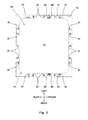
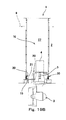
- a thruster arrangement portion 10 that is open in the upper-lower direction is provided at a predetermined position of a hull 2, and a thruster 3 is provided so as to project downward from a lower opening portion 11 formed at a bottom portion of the thruster arrangement portion 10.
- a horizontal cross section of the thruster arrangement portion 10 is a rectangular cross section.
- the thruster arrangement portion 10 extends from an upper opening portion 12 to a lower side while keeping the same cross section.
- the lower opening portion 11 whose cross-sectional area is smaller is formed at a lower end of the thruster arrangement portion 10.
- Wall surfaces 13 around the thruster arrangement portion 10 are also referred to as a hull structure 2. Since the hull 2 and the hull structure 2 are the same in configuration as each other, the same reference sign is used.
- the thruster 3 is provided at a storage seat 20 that stores the thruster 3 and a thruster driving device (motor) 4.
- An outer shape of the storage seat 20 is formed such that the storage seat 20 is movable in the upper-lower direction in an internal space 17 of the thruster arrangement portion 10.
- the size of a lower portion of the storage seat 20 is set such that a predetermined gap is formed between the lower portion of the storage seat 20 and the lower opening portion 11 formed at the lower end of the thruster arrangement portion 10.
- the lower opening portion 11 is formed at a structural portion 14 having a predetermined thickness at a hull bottom portion.
- An upper surface of the lower opening portion 11 is an attachment seat 15 for fixing a flange portion 21 provided around the storage seat 20.
- a lower surface of the structural portion 14 is a ship bottom member 16.
- the storage seat 20 is attached such that a lower portion thereof is inserted in the structural portion 14 of the lower opening portion 11.
- the thruster 3 projects downward from a ship bottom.
- the storage seat 20 is provided with a storage portion 22 located at a position above the flange portion 21 fixed to the attachment seat 15, and a driving device 4 is provided at an upper portion of the storage portion 22.
- the thruster 3 of the present embodiment is attached to a lower surface of the storage seat 20, and a driving shaft 5 thereof extends through the inside of the storage portion 22 to be coupled to the driving device 4. It should be noted that components other than the driving device 4 are not shown. By detaching the flange portion 21 of the storage seat 20 from the attachment seat 15 of the hull, the thruster 3 can be detached integrally with the storage seat 20.
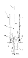
- Each of locking devices 30 configured to hold the flange portion 21 at the attachment seat 15 in a state where below-described fixing units 60 are detached is provided between the flange portion 21 provided around the storage seat 20 and the attachment seat 15 of the hull.
- a plurality of locking devices 30 are provided around the thruster arrangement portion 10.
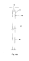
- Each of the locking devices 30 is provided with a power transmission shaft 31 extending along the wall surface 13 of the thruster arrangement portion 10 to an upper portion of the thruster arrangement portion 10.
- the power transmission shaft 31 is supported by a plurality of bearings 32 provided at the wall surface 13, and parts of the power transmission shaft 31 are coupled to each other by a joint 33, provided at an intermediate portion of the power transmission shaft 31, so as to be continuous in the upper-lower direction of the thruster arrangement portion 10.
- a rotary driving unit configured to activate or release the locking device 30 is provided at an upper portion of the power transmission shaft 31.
- the locking device 30 of the present embodiment can be activated or released through the power transmission shaft 31.
- a component that rotates the power transmission shaft 31 may be a component, such as a rotary ram (not shown), which rotates the power transmission shaft 31 by fluid pressure.
- a mechanical drive component such as the rotary ram
- a plurality of power transmission shafts 31 can be rotated at the same time.
- the present embodiment has explained an example of the rotary driving unit configured to activate or release the locking device 30 by the rotary operation.
- a driving unit may be used, which activates or releases the locking device 30 by a linear operation of causing the power transmission shaft 31 to move in the upper-lower direction.
- the type of the driving unit may be determined in accordance with the configuration of the locking device.
- Lifting guides 40 are provided at the wall surfaces 13 of the thruster arrangement portion 10 so as to extend in the upper-lower direction.
- Each of the lifting guides 40 is provided continuously from a lower portion of the thruster arrangement portion 10 to the upper portion thereof.
- two lifting guides 40 are respectively provided at positions opposed to each other about a left-right-direction center of the storage seat 20.
- the storage seat 20 is guided in the upper-lower direction along the lifting guides 40 in the thruster arrangement portion 10.
- a plurality of lift-down guides 41 which are used when the storage seat 20 taken out upward from the thruster arrangement portion 10 is suspended to be put into the thruster arrangement portion 10, are provided at the upper portion of the thruster arrangement portion 10.
- upper ends of the lift-down guides 41 are formed as inclined portions (see Fig. 1 ).
- the lifting guides 40 are respectively arranged at two opposing positions of the wall surfaces 13 of the thruster arrangement portion 10 having the rectangular cross section. These two lifting guides 40 extends continuously from the lower portion of the thruster arrangement portion 10 to the upper portion thereof.
- the lifting guides 40 are respectively provided at short-side wall surfaces (left and right wall surfaces) 13 of the rectangular cross section. Since the lifting guides 40 are respectively provided at the short sides, a distance between the lifting guides 40 can be made long, that is, can be set to a distance of a long-side wall surface (front or rear wall surface). Thus, the lifting guides 40 can stably guide the storage seat 20.
- lifting guide metal fittings 23 provided at the flange portion 21 (shown by a chain double-dashed line) of the storage seat 20 are guided along the opposing wall surfaces 13 of the thruster arrangement portion 10.
- a plurality of lift-down guides 41 provided at the upper portion of the thruster arrangement portion 10 are provided around the thruster arrangement portion 10.
- two lift-down guides 41 are provided at each of the surfaces of the thruster arrangement portion 10 having the rectangular cross section.
- the lift-down guides 41 are provided such that a predetermined gap is formed between each lift-down guide 41 and the periphery of the flange portion 21 of the storage seat 20.
- the flange portion 21 shown by the chain double-dashed line in Fig. 2 can be inserted into a center portion of the thruster arrangement portion 10.
- the storage seat 20 to which the thruster 3 is attached is provided such that a center of the storage portion 22 is located at a position displaced forward from a center of the thruster arrangement portion 10.
- the flange portion 21 provided around the storage seat 20 is fixed to the attachment seat 15 by a plurality of fixing bolts (fixing units) 60.
- the fixing bolts 60 can be attached and detached inside the thruster arrangement portion 10.
- Fig. 3 shows a part of the plurality of fixing bolts 60.
- the fixing bolts 60 are provided at regular intervals along a dashed line of Fig. 3 over the entire periphery.
- a web member 26 couples a surface member 24 provided so as to be flush with the flange portion 21 of the storage seat 20 and a bottom plate member 25 (see Fig. 1 ) provided at the lower surface of the storage seat 20.
- the surface member 24 is provided with opening portions 27 formed at portions other than a portion where the web member 26 is provided.
- the surface member 24 and the web member 26 constitute a girder member 28 that is a strengthening member.
- a plurality of locking devices 30 are provided around the attachment seat 15.
- three locking devices 30 are provided at each of the wall surfaces 13 of the rectangular cross section.
- the locking devices 30 are provided at opposing positions located on extended lines of the web member 26 of the girder member 28.
- the locking devices 30 hold a structural portion of the storage seat 20.
- the locking devices 30 are provided at the opposing positions on the extended lines of the girder member 28, so that even in a case where the flange portion 21 of the storage seat 20 is bent in the upper-lower direction by water pressure or the like, the storage seat 20 can be stably held at portions at each of which a bent amount is small.
- the locking devices 30 do not have to be provided at all the opposing positions on the extended lines of the girder member 28.
- Insertion guides 70 are respectively provided at positons of the attachment seat 15 respectively close to the wall surfaces 13 at which the lifting guides 40 are respectively provided. With this, the storage seat 20 inserted in the thruster arrangement portion 10 is arranged at a predetermined position of the attachment seat 15. The insertion guides 70 are provided at the attachment seat 15 so as to be respectively located at opposing positions of the lower opening portion 11. The details of the insertion guides 70 will be described later.
- the lifting guides 40 are respectively provided substantially at left and right sides of a center line of the storage portion 22 whose center is displaced as described above. With this, the lifting guides 40 guide portions of the vicinities of front-rear direction gravity centers of the storage seat 20 and the thruster 3.
- the lifting guide 40 is provided so as to project from the wall surface 13 of the thruster arrangement portion 10 toward the internal space 17.
- the lifting guide 40 is supported by lifting guide supporting members 42 provided at the wall surface 13 of the thruster arrangement portion 10.
- a guide portion 43 is formed at an upper end of the lifting guide 40 of the present embodiment.
- the guide portion 43 is formed to have inclined surfaces that decrease in size toward the upper side in a width direction and a wall surface direction, so that the flange portion 21 of the storage seat 20 is easily inserted from above.
- the lifting guide metal fitting 23 guided by the lifting guide 40 is formed in a U shape so as to be guided along three surfaces by the lifting guide 40.
- the lifting guide metal fitting 23 is fixed to the flange portion 21 of the storage seat 20.
- a gap Cg between the lifting guide metal fitting 23 and the lifting guide 40 is formed in each of the left-right direction and the front-rear direction. These gaps Cg are determined depending on a relation with the insertion guide 70 as described later.
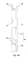
- a lifting guide 45 shown in Figs. 6A and 6B is one example different from the lifting guide 40 shown in Figs. 4A and 4B .
- the lifting guide 45 is constituted by a lower lifting guide 46 and an upper lifting guide 47.
- the upper lifting guide 47 is the same as the lifting guide 40 shown in Figs. 4A and 4B .
- the gap Cg between the lower lifting guide 46 and the lifting guide metal fitting 23 is narrower.
- An upper end portion of the lower lifting guide 46 is obliquely cut such that when lifting down the storage seat 20, the lifting guide metal fitting 23 can easily move from the upper lifting guide 47 to the lower lifting guide 46. Since the other components are the same as those of the lifting guide 40, the same reference signs are used.
- the lifting guide metal fitting 23 is lifted up and down in a state where there is the gap Cg between the upper lifting guide 47 and the lifting guide metal fitting 23.
- the lifting guide metal fitting 23 is lifted up and down in a state where there is a gap Ca between the lower lifting guide 46 and the lifting guide metal fitting 23.
- the gap Ca between the lower lifting guide 46 and the lifting guide metal fitting 23 is small, the storage seat 20 lifted down to the thruster arrangement portion 10 integrally with the thruster 3 can be guided and lifted down to a more accurate position.
- an upper lifting guide metal fitting 51 may be provided at a makeshift upper lifting guide metal fitting attachment base 50 provided at an upper portion of the storage seat 20.
- the upper lifting guide metal fitting attachment base 50 is provided at a position to which the driving device 4 of the storage seat 20 is attached.
- the upper lifting guide metal fitting 51 provided at the upper lifting guide metal fitting attachment base 50 is provided on a vertical line of the lifting guide metal fitting 23 provided at the flange portion 21 of the storage seat 20.
- the upper lifting guide metal fitting 51 By providing the upper lifting guide metal fitting 51 as above, the upper lifting guide metal fitting 51 and the lifting guide metal fitting 23 of the flange portion 21 are guided by the lifting guide 40 in a state where the upper lifting guide metal fitting 51 and the lifting guide metal fitting 23 are spaced apart from each other in the upper-lower direction. Therefore, when integrally lifting up and down the storage seat 20 and the thruster 3, the lifting guides 40 can guide the storage seat 20 and the thruster 3 more stably.
- the inclination of the thruster 3 when the thruster 3 is lifted up and down can be prevented by the upper lifting guide metal fittings 51 provided at the upper lifting guide metal fitting attachment bases 50 and the lifting guide metal fittings 23 provided at the flange portion 21, that is, by the support at four points that are two points at upper left and right sides of the storage seat 20 and two points at lower left and right sides of the storage seat 20.
- Figs. 8 and 9 shows different components, and the other components are not shown.
- the flange portion 21 of the storage seat 20 is fixed to the hull 2 by the fixing bolts 60 provided at the attachment seat 15 of the hull structure 2.
- the fixing bolts 60 of the present embodiment are stud bolts implanted in the attachment seat 15.
- the fixing bolt 60 is inserted in a bolt hole 61 formed on the flange portion 21, and a nut 62 is tightened to the fixing bolt 60 from above to be fixed.
- the seal member 29 is provided at a lower surface of the flange portion 21 so as to be located at an inner side of the fixing bolt 60 of the flange portion 21.
- the seal member 29 By fixing the flange portion 21 to the attachment seat 15 by the fixing bolts 60, the lower surface of the flange portion 21 and an upper surface of the attachment seat 15 tightly contact each other to be sealed by the seal member 29.
- an O ring is used as the seal member 29.
- the insertion guide 70 includes: an insertion guide pin 71 provided between the fixing bolts 60; and a pin hole 72 which is formed on the flange portion 21 and through which the insertion guide pin 71 is inserted.
- a tapered portion 73 that decreases in diameter is formed at an upper portion of the insertion guide pin 71, so that the insertion guide pin 71 is easily, upwardly inserted through the pin hole 72 of the flange portion 21.
- the pin hole 72 of the storage seat 20 lifted down is guided by the insertion guide pin 71, so that the fixing bolts 60 are respectively inserted into the bolt holes 61 of the flange portion 21.
- a relation among a gap Cb between the fixing bolt 60 and the bolt hole 61 of the flange portion 21, a gap Cp between the insertion guide pin 71 and the pin hole 72 of the flange portion 21, and the gap Cg between the lifting guide 40 and the lifting guide metal fitting 23 provided at the flange portion 21 of the storage seat 20 is set so as to become a relation "Cp ⁇ Cb ⁇ Cg".
- a height h of the insertion guide pin 71 is slightly higher than an upper end position of the fixing bolt 60.
- the height h is set such that when the flange portion 21 is located at a lower end of the tapered portion 73, the flange portion 21 does not contact the fixing bolt 60.
- the fixing bolts 60 are the stud bolts
- the pin holes 72 of the flange portion 21 of the storage seat 20 lifted down are positioned by the insertion guide pins 71, and therefore, the bolt holes 61 are positioned.
- the storage seat 20 can be positioned relative to the attachment seat 15 without causing the fixing bolts 60 and the bolt holes 61 of the flange portion 21 to contact each other.
- the storage seat 20 to be lifted down in a suspended state from above the thruster arrangement portion 10 can be lifted down to an accurate position of the attachment seat 15.
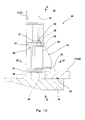
- Fig. 12 is a diagram taken along line XII-XII of Fig. 13.
- Fig. 13 is a diagram taken along line XIII-XIII of Fig. 12 .
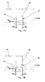
- the locking device 30 is provided at a corner portion between the hull structure 2 that is the wall surface 13 of the thruster arrangement portion 10 and the attachment seat 15.
- the locking device 30 includes the locking piece 34 that projects toward the flange portion 21 of the storage seat 20 or is stored toward the wall surface 13.
- a rotating shaft portion 35 of the locking piece 34 is supported by an attachment base 80 provided so as to project inward from the hull structure 2.
- the attachment base 80 includes plate-shaped members 81 spaced apart from each other in the upper-lower direction by a predetermined distance and each having a predetermined thickness. Each of the plate-shaped members 81 is provided with an attachment hole 82 penetrating therethrough in the upper-lower direction. Support shafts 36 respectively provided at upper and lower sides of the rotating shaft portion 35 are respectively inserted into the attachment holes 82. With this, the rotating shaft portion 35 is rotatably supported, so that the locking piece 34 is rotatable in a horizontal direction. Since the locking piece 34 is supported on the hull structure 2 by the attachment base 80, the load supported by the locking piece 34 is supported by the hull structure 2.
- the locking piece 34 is provided with a rotary driving shaft 37 projecting upward and provided at an upper portion of the support shaft 36 provided at an upper portion of the rotating shaft portion 35.
- the rotary driving shaft 37 of the present embodiment is formed to have a rectangular cross section.
- the rotary driving shaft 37 is coupled to an expansion joint 38 provided at a lower end of the power transmission shaft 31 located above the rotary driving shaft 37.
- the expansion joint 38 allows movements of the rotary driving shaft 37 in the upper-lower direction. With this, by rotating the power transmission shaft 31, the rotating shaft portion 35 of the locking piece 34 can be rotated through the expansion joint 38. Even if the rotating shaft portion 35 is displaced upward, the expansion joint 38 absorbs the upward displacement of the rotary driving shaft 37, so that the upward displacement is not transmitted to the power transmission shaft 31.
- the upward load acting on the locking piece 34 is supported by the hull structure 2 through the attachment base 80. Therefore, the upward load does not act on the power transmission shaft 31 coupled to the rotary driving shaft 37 of the rotating shaft portion 35 through the expansion joint 38.
- the locking device 30 provided at the lower portion of the thruster arrangement portion 10 can be operated.
- the locking piece 34 can be rotated in the horizontal direction in a range of about 90° in plan view.
- a wedge seat 90 with which the locking piece 34 engages is provided at the flange portion 21 of the storage seat 20. From a position shown by a chain double-dashed line in Fig. 14 , the locking piece 34 is rotated about 90° toward the wedge seat 90 to engage with an upper surface of the wedge seat 90. Thus, the locking piece 34 becomes a locked state.
- a stopper 83 with which the locking piece 34 contacts when the locking piece 34 is rotated toward the wall surface 13 is provided at the attachment base 80. The position which is shown by the chain double-dashed line and at which the locking piece 34 contacts the stopper 83 is a stored position, and the locking piece 34 is in an unlocked state.
- the upper surface of the wedge seat 90 is formed as a tapered surface 91 having an angle ⁇ by which a wedge effect can be obtained.
- An engagement surface 39 of the locking piece 34 that engages with the wedge seat 90 is also formed to have the angle ⁇ that is the same as the angle of the upper surface of the wedge seat 90.
- the angle ⁇ is set depending on a force necessary to rotate the locking piece 34, a contact area, and the like.
- the locking devices 30 are in the locked states, and the flange portion 21 of the storage seat 20 is being fixed to the attachment seat 15 by the fixing bolts 60 (see Fig. 3 ).
- the components, such as the driving device 4, which drive the thruster 3 are also being attached.
- the locking devices 30 may be the locked states or the unlocked states. However, the present embodiment explains a case where in the operating state, the locking devices 30 are in the locked states.
- the driving device 4 and the other components are detached, and waterproof covers and the like are attached to respective portions.
- the specific preparation for detaching the thruster 3 for example, pipes, electric wires, the driving device 4, the driving shaft 5, a lubricating oil pump unit, a swivel pump unit, and a swivel valve unit are detached, and the waterproof covers and the like are attached to those components.
- a wire 7 of a lift-up device is attached to predetermined positions of the storage seat 20.
- the locked states of the locking devices 30 are reconfirmed, and the fixing of the flange portion 21 by the fixing bolts 60 is released.
- the fixing of the flange portion 21 is released in such a manner that an operator gets into the internal space 17 of the thruster arrangement portion 10.
- the operator can operate in a dry environment.
- the storage seat 20 is held at the attachment seat 15 only by the locking devices 30.
- the fixing bolts 60 are detached, the upward load acting on the thruster 3 and the storage seat 20 by the water-level difference between the inside of the thruster arrangement portion 10 and the outside of the hull is held at the hull structure by the locking devices 30 provided at plural positions around the storage seat 20.
- the operating lever 55 When the water is poured to the same level as the outer draft 8, the operating lever 55 is attached to the upper portion of the power transmission shaft 31, and the operator rotates the operating lever 55. Thus, the power transmission shaft 31 is rotated. With this, the locking piece 34 of the locking device 30 is rotated to be unlocked (the state of the locking piece 34 shown by the chain double-dashed line in Fig. 14 ). At this time, the water pressure acting on the thruster 3 and the storage seat 20 from outside and the water pressure acting on the thruster 3 and the storage seat 20 from inside are balanced. In addition, the total of downward own weights of the storage seat 20 and the thruster 3 is larger than upward buoyant force acting on the storage seat 20 and the thruster 3, and these downward loads are supported by the attachment seat 15. Therefore, the upward load is not acting on the locking piece 34. On this account, the locking piece 34 can be easily rotated.
- divers confirms whether or not the locking devices 30 are unlocked. This operation by the divers is just a confirmation of the unlocked states, so that it is easy. In addition, since the divers get into the thruster arrangement portion 10 to perform this operation, the operation can be easily performed regardless of marine weather outside the ship.
- the storage seat 20 is lifted up by the wire 7 of the lift-up device, such as a winch or a crane.
- the storage seat 20 is lifted up in a state where the lifting guide metal fittings 23 of the flange portion 21 are guided by the lifting guides 40 (see Figs. 2 and 3 ). Therefore, the storage seat 20 and the thruster 3 can be integrally, stably lifted up.
- the weight lifted up by the wire 7 is weight obtained by subtracting the buoyant force acting on the storage seat 20 and the thruster 3 from the total of the own weights of the storage seat 20 and the thruster 3.
- the weight lifted up by the wire 7 is the total of the own weights of the thruster 3 and the storage seat 20. Therefore, by the winch, the crane, or the like capable of lifting up such weight, the thruster 3 can be detached in the ship. Therefore, a special lifting device for heavy weight is not required, and the thruster 3 and the storage seat 20 can be lifted up and down by a normal simple winch or the like.
- the thruster 3 lifted up from the thruster arrangement portion 10 in the ship is inspected or repaired at a predetermined place.
- the thruster 3 projecting downward from the hull structure 2 can be detached at a position above the draft surface in the ship by a simple handling device using a winch, a crane, or the like, and the thruster 3 can be inspected, repaired, or the like.
- the thruster 3 fixed integrally with the storage seat 20 is lifted down by the winch, the crane, or the like to be put into the thruster arrangement portion 10.
- the flange portion 21 of the storage seat 20 is guided by the lift-down guides 41 (see Fig. 2 ) provided at the upper portion of the thruster arrangement portion 10.
- the thruster 3 can be lifted down such that the lifting guide metal fittings 23 of the flange portion 21 respectively engage with the lifting guides 40 provided at the thruster arrangement portion 10 (see Figs. 2 and 3 ).
- the power transmission shafts 31 are rotated by the operating levers 55 attached to the upper portions of the power transmission shafts 31.
- the locking pieces 34 of the locking devices 30 are rotated to respectively engage with the wedge seats 90 provided at the flange portion 21 of the storage seat 20.
- the flange portion 21 is locked to the attachment seat 15 (see a solid line in Fig. 14 ).
- the locking pieces 34 are rotated toward the tapered surfaces 91 of the wedge seats 90. Therefore, even underwater, the locking pieces 34 can surely engage with the wedge seats 90.
- the locked states by the locking devices 30 are confirmed such that the divers get into water in the thruster arrangement portion 10.
- This confirmation operation by the divers is just the confirmation of the locked states, so that it is easy.
- the operation can be easily performed regardless of the marine weather outside the ship.
- the entire water in the thruster arrangement portion 10 is discharged.
- the flange portion 21 and the attachment seat 15 are fixed to each other by the locking devices 30 as described above, the internal space 17 of the thruster arrangement portion 10 is sealed water-tightly by the seal member 29 provided between the flange portion 21 and the attachment seat 15.
- the inside of the thruster arrangement portion 10 becomes the dry environment (space).
- the wire 7 of a lift-up device is detached.
- the flange portion 21 around the storage seat 20 is fixed by the fixing bolts 60 provided at the attachment seat 15 (see the state shown by the solid line in Fig. 11 ). Since these operations are performed after the water is discharged from the thruster arrangement portion 10, these are performed in the dry environment and can be easily performed. With this, the storage seat 20 and the thruster 3 are fixed to the hull structure 2.
- the waterproof covers and the like attached when detaching the thruster 3 are detached.
- various components are attached. Although many of the components are not shown, specifically, pipes, electric wires, the driving device 4, the driving shaft 5, the lubricating oil pump unit, the swivel pump unit, the swivel valve unit, and the like are attached. After the components are attached, the adjustment of the devices and the confirmation of the driving are performed.
- the thruster 3 can be attached to the lower portion of the thruster arrangement portion 10 in the ship by the simple handling device using the winch, the crane, or the like.
- the thruster 3 projecting from the ship bottom can be detached in the ship. Therefore, the thruster 3 detached in the ship can be inspected, repaired, or the like in the ship.
- the detached thruster 3 After the detached thruster 3 is inspected or repaired, it may be attached to the thruster arrangement portion 10, or while the detached thruster 3 is being inspected or repaired, the other thruster 3 may be arranged at the thruster arrangement portion 10. Thus, while maintaining the point holding or the like of the hull, a part of the thrusters 3 can be easily inspected, repaired, or replaced.
- the inboard detachable thruster apparatus 1 can be configured at low cost.
- the operation of detaching the thruster 3 in the ship does not have to be performed underwater outside the ship, the operation of detaching the thruster 3 can be quickly performed without being affected by weather at the time of malfunctions or the like of the thruster 3.
- the implanted fixing bolts (fixing units) 60 are used as the fixing units that fix the flange portion 21 of the storage seat 20 to the attachment seat 15.
- the fixing units may be tap bolts to be inserted from above the flange portion 21 or may be the other units.
- the fixing units are not limited to the above embodiment.
- the locking device 30 of the above embodiment becomes the locked state in such a manner that the locking piece 34 engages with the wedge seat 90.
- the locking device may become the locked state by a component other than the wedge seat 90.
- the configuration of the locking device 30 is not limited to the above embodiment.
- the locking device 30 is activated or released by rotating the locking piece 34.
- the locking device 30 may be activated or released by a linear movement method instead of the rotary movement method, and the method is not limited to the above embodiment.
- lifting guide 40 is not limited to the above embodiment.
- the inboard detachable thruster apparatus according to the present invention can be utilized in the drilling ship or the like in which the thruster is desired to be detached in the ship to be inspected, repaired, or the like while the point holding or the like of the ship is being performed on the ocean.
Landscapes
- Chemical & Material Sciences (AREA)
- Engineering & Computer Science (AREA)
- Combustion & Propulsion (AREA)
- Mechanical Engineering (AREA)
- Ocean & Marine Engineering (AREA)
- Earth Drilling (AREA)
- Load-Engaging Elements For Cranes (AREA)
- Barrages (AREA)
Applications Claiming Priority (2)
| Application Number | Priority Date | Filing Date | Title |
|---|---|---|---|
| JP2012158929 | 2012-07-17 | ||
| PCT/JP2013/004346 WO2014013724A1 (ja) | 2012-07-17 | 2013-07-16 | 船内取外し式スラスタ装置 |
Publications (3)
| Publication Number | Publication Date |
|---|---|
| EP2876040A1 true EP2876040A1 (de) | 2015-05-27 |
| EP2876040A4 EP2876040A4 (de) | 2016-03-30 |
| EP2876040B1 EP2876040B1 (de) | 2019-01-16 |
Family
ID=49948566
Family Applications (1)
| Application Number | Title | Priority Date | Filing Date |
|---|---|---|---|
| EP13820414.4A Active EP2876040B1 (de) | 2012-07-17 | 2013-07-16 | Schiffsinterne verdrängungstriebwerkvorrichtung |
Country Status (4)
| Country | Link |
|---|---|
| EP (1) | EP2876040B1 (de) |
| JP (1) | JP5802335B2 (de) |
| KR (1) | KR20150027247A (de) |
| WO (1) | WO2014013724A1 (de) |
Families Citing this family (2)
| Publication number | Priority date | Publication date | Assignee | Title |
|---|---|---|---|---|
| CN109080806A (zh) * | 2018-09-21 | 2018-12-25 | 昆山耀和体育用品有限公司 | 一种可快速安拆推进器的皮划艇 |
| KR102211880B1 (ko) * | 2020-01-09 | 2021-02-03 | 케이오티 (주) | 트러스터 수중 설치장치 |
Family Cites Families (9)
| Publication number | Priority date | Publication date | Assignee | Title |
|---|---|---|---|---|
| JPS3814234B1 (de) * | 1960-12-05 | 1963-08-06 | ||
| GB1040621A (en) * | 1962-03-23 | 1966-09-01 | Reiners Walter | A marine outboard drive |
| JPS5926397A (ja) * | 1982-08-04 | 1984-02-10 | Kawasaki Heavy Ind Ltd | 水中交換型旋回式スラスタ着脱装置 |
| BR9813875A (pt) | 1997-10-23 | 2000-09-26 | Rsv Gusto Eng Bv | Vaso provido com um empurrador retrátil |
| JP3643734B2 (ja) * | 1999-08-23 | 2005-04-27 | 三菱重工業株式会社 | スラスタ昇降装置 |
| GB0702791D0 (en) * | 2007-02-14 | 2007-03-28 | Rolls Royce Plc | Linear actuator |
| CA2763257A1 (en) * | 2009-05-28 | 2010-12-02 | Gerd Krautkraemer | Rudder propeller ship propulsion system and ship equipped therewith and assembly and disassembly process therefor |
| SG175035A1 (en) * | 2010-04-16 | 2011-11-28 | Waertsilae Finland Oy | Mounting method of thruster |
| JP2012101580A (ja) * | 2010-11-08 | 2012-05-31 | Mitsubishi Heavy Ind Ltd | 洋上における推進装置のメンテナンス方法 |
-
2013
- 2013-07-16 EP EP13820414.4A patent/EP2876040B1/de active Active
- 2013-07-16 JP JP2014525719A patent/JP5802335B2/ja active Active
- 2013-07-16 KR KR20157001948A patent/KR20150027247A/ko not_active Ceased
- 2013-07-16 WO PCT/JP2013/004346 patent/WO2014013724A1/ja not_active Ceased
Also Published As
| Publication number | Publication date |
|---|---|
| EP2876040A4 (de) | 2016-03-30 |
| JP5802335B2 (ja) | 2015-10-28 |
| JPWO2014013724A1 (ja) | 2016-06-30 |
| EP2876040B1 (de) | 2019-01-16 |
| KR20150027247A (ko) | 2015-03-11 |
| WO2014013724A1 (ja) | 2014-01-23 |
Similar Documents
| Publication | Publication Date | Title |
|---|---|---|
| JP3413196B2 (ja) | 積卸し式浮標 | |
| AU2011250766B2 (en) | System for lifting thrusters for providing maintenance to thrusters of floating vessels | |
| US20120231682A1 (en) | vessel with a retractable thruster assembly | |
| US9254894B2 (en) | Flotable subsea platform (FSP) | |
| US11739732B2 (en) | Off-shore wind turbine system and method of installation | |
| RU2601086C2 (ru) | Способ швартовки судна и устройство для осуществления этого способа | |
| CN110758702A (zh) | 一种可船内维护的伸缩式推进器系统 | |
| EP2001737B1 (de) | Verbindungssystem und verfahren zur verbindung und trennung einer schwimmeinheit mit und von einer mit einer unterwasserinstallation verbundenen boje | |
| US8544400B2 (en) | Mooring arrangement | |
| KR20240004955A (ko) | 해상 자기-엘리베이팅 선박과 함께 사용하도록 구성된 수송 선박용 랙 구조물을 위한 시스템들 및 방법들 | |
| EP2876040B1 (de) | Schiffsinterne verdrängungstriebwerkvorrichtung | |
| US8181589B2 (en) | Gravity anchor | |
| KR102247619B1 (ko) | 부유식풍력발전기의 상부타워를 이송하기 위한 운송장치 | |
| JP2024507604A (ja) | 海洋発電プラントアセンブリ | |
| KR20260046093A (ko) | 관절형 기계식 커넥터 및 그 사용 방법 | |
| EP2610160B1 (de) | System zum Anheben von Propellergondeln zur Bereitstellung der Wartung von Propellergondeln von schwimmenden Schiffskörpern | |
| KR20180042940A (ko) | 스러스터의 프로펠러 고정부가 안착되는 크래들 및 승강장치로 프로펠러 고정부를 리프팅하는 방법 | |
| EP2909082B1 (de) | Strahlruderanordnung in einem wasserfahrzeug | |
| EP2909081B1 (de) | Verschlussdeckel zum schliessen des unteren teils einer hebekammer in der hülle eines wasserfahrzeugs und verfahren zur ermöglichung des zugangs zum unteren teil der hebekammer | |
| JP6959928B2 (ja) | 海洋発電システム | |
| NL2015981B1 (en) | Fairlead for a mooring leg | |
| KR101487460B1 (ko) | 선박의 레그 탑재 방법 | |
| Murray et al. | Disconnectable Mooring System for Ice Class Floaters | |
| KR101498208B1 (ko) | 추진기의 유지보수 장치 | |
| Hendriks et al. | 3rd generation Thruster Retrieval System taking Thruster Maintenance Planning off the Critical Path |
Legal Events
| Date | Code | Title | Description |
|---|---|---|---|
| PUAI | Public reference made under article 153(3) epc to a published international application that has entered the european phase |
Free format text: ORIGINAL CODE: 0009012 |
|
| 17P | Request for examination filed |
Effective date: 20150217 |
|
| AK | Designated contracting states |
Kind code of ref document: A1 Designated state(s): AL AT BE BG CH CY CZ DE DK EE ES FI FR GB GR HR HU IE IS IT LI LT LU LV MC MK MT NL NO PL PT RO RS SE SI SK SM TR |
|
| AX | Request for extension of the european patent |
Extension state: BA ME |
|
| DAX | Request for extension of the european patent (deleted) | ||
| RA4 | Supplementary search report drawn up and despatched (corrected) |
Effective date: 20160226 |
|
| RIC1 | Information provided on ipc code assigned before grant |
Ipc: B63H 5/125 20060101AFI20160222BHEP |
|
| GRAP | Despatch of communication of intention to grant a patent |
Free format text: ORIGINAL CODE: EPIDOSNIGR1 |
|
| STAA | Information on the status of an ep patent application or granted ep patent |
Free format text: STATUS: GRANT OF PATENT IS INTENDED |
|
| RIC1 | Information provided on ipc code assigned before grant |
Ipc: B63H 5/125 20060101AFI20180619BHEP |
|
| INTG | Intention to grant announced |
Effective date: 20180724 |
|
| GRAS | Grant fee paid |
Free format text: ORIGINAL CODE: EPIDOSNIGR3 |
|
| GRAA | (expected) grant |
Free format text: ORIGINAL CODE: 0009210 |
|
| STAA | Information on the status of an ep patent application or granted ep patent |
Free format text: STATUS: THE PATENT HAS BEEN GRANTED |
|
| AK | Designated contracting states |
Kind code of ref document: B1 Designated state(s): AL AT BE BG CH CY CZ DE DK EE ES FI FR GB GR HR HU IE IS IT LI LT LU LV MC MK MT NL NO PL PT RO RS SE SI SK SM TR |
|
| REG | Reference to a national code |
Ref country code: GB Ref legal event code: FG4D |
|
| REG | Reference to a national code |
Ref country code: CH Ref legal event code: EP |
|
| REG | Reference to a national code |
Ref country code: IE Ref legal event code: FG4D |
|
| REG | Reference to a national code |
Ref country code: DE Ref legal event code: R096 Ref document number: 602013049994 Country of ref document: DE |
|
| REG | Reference to a national code |
Ref country code: AT Ref legal event code: REF Ref document number: 1089508 Country of ref document: AT Kind code of ref document: T Effective date: 20190215 |
|
| REG | Reference to a national code |
Ref country code: NO Ref legal event code: T2 Effective date: 20190116 |
|
| REG | Reference to a national code |
Ref country code: NL Ref legal event code: MP Effective date: 20190116 |
|
| REG | Reference to a national code |
Ref country code: LT Ref legal event code: MG4D |
|
| PG25 | Lapsed in a contracting state [announced via postgrant information from national office to epo] |
Ref country code: NL Free format text: LAPSE BECAUSE OF FAILURE TO SUBMIT A TRANSLATION OF THE DESCRIPTION OR TO PAY THE FEE WITHIN THE PRESCRIBED TIME-LIMIT Effective date: 20190116 |
|
| REG | Reference to a national code |
Ref country code: AT Ref legal event code: MK05 Ref document number: 1089508 Country of ref document: AT Kind code of ref document: T Effective date: 20190116 |
|
| PG25 | Lapsed in a contracting state [announced via postgrant information from national office to epo] |
Ref country code: LT Free format text: LAPSE BECAUSE OF FAILURE TO SUBMIT A TRANSLATION OF THE DESCRIPTION OR TO PAY THE FEE WITHIN THE PRESCRIBED TIME-LIMIT Effective date: 20190116 Ref country code: SE Free format text: LAPSE BECAUSE OF FAILURE TO SUBMIT A TRANSLATION OF THE DESCRIPTION OR TO PAY THE FEE WITHIN THE PRESCRIBED TIME-LIMIT Effective date: 20190116 Ref country code: ES Free format text: LAPSE BECAUSE OF FAILURE TO SUBMIT A TRANSLATION OF THE DESCRIPTION OR TO PAY THE FEE WITHIN THE PRESCRIBED TIME-LIMIT Effective date: 20190116 Ref country code: PL Free format text: LAPSE BECAUSE OF FAILURE TO SUBMIT A TRANSLATION OF THE DESCRIPTION OR TO PAY THE FEE WITHIN THE PRESCRIBED TIME-LIMIT Effective date: 20190116 Ref country code: PT Free format text: LAPSE BECAUSE OF FAILURE TO SUBMIT A TRANSLATION OF THE DESCRIPTION OR TO PAY THE FEE WITHIN THE PRESCRIBED TIME-LIMIT Effective date: 20190516 |
|
| PG25 | Lapsed in a contracting state [announced via postgrant information from national office to epo] |
Ref country code: RS Free format text: LAPSE BECAUSE OF FAILURE TO SUBMIT A TRANSLATION OF THE DESCRIPTION OR TO PAY THE FEE WITHIN THE PRESCRIBED TIME-LIMIT Effective date: 20190116 Ref country code: BG Free format text: LAPSE BECAUSE OF FAILURE TO SUBMIT A TRANSLATION OF THE DESCRIPTION OR TO PAY THE FEE WITHIN THE PRESCRIBED TIME-LIMIT Effective date: 20190416 Ref country code: GR Free format text: LAPSE BECAUSE OF FAILURE TO SUBMIT A TRANSLATION OF THE DESCRIPTION OR TO PAY THE FEE WITHIN THE PRESCRIBED TIME-LIMIT Effective date: 20190417 Ref country code: IS Free format text: LAPSE BECAUSE OF FAILURE TO SUBMIT A TRANSLATION OF THE DESCRIPTION OR TO PAY THE FEE WITHIN THE PRESCRIBED TIME-LIMIT Effective date: 20190516 Ref country code: LV Free format text: LAPSE BECAUSE OF FAILURE TO SUBMIT A TRANSLATION OF THE DESCRIPTION OR TO PAY THE FEE WITHIN THE PRESCRIBED TIME-LIMIT Effective date: 20190116 Ref country code: HR Free format text: LAPSE BECAUSE OF FAILURE TO SUBMIT A TRANSLATION OF THE DESCRIPTION OR TO PAY THE FEE WITHIN THE PRESCRIBED TIME-LIMIT Effective date: 20190116 |
|
| REG | Reference to a national code |
Ref country code: DE Ref legal event code: R097 Ref document number: 602013049994 Country of ref document: DE |
|
| PG25 | Lapsed in a contracting state [announced via postgrant information from national office to epo] |
Ref country code: DK Free format text: LAPSE BECAUSE OF FAILURE TO SUBMIT A TRANSLATION OF THE DESCRIPTION OR TO PAY THE FEE WITHIN THE PRESCRIBED TIME-LIMIT Effective date: 20190116 Ref country code: AT Free format text: LAPSE BECAUSE OF FAILURE TO SUBMIT A TRANSLATION OF THE DESCRIPTION OR TO PAY THE FEE WITHIN THE PRESCRIBED TIME-LIMIT Effective date: 20190116 Ref country code: AL Free format text: LAPSE BECAUSE OF FAILURE TO SUBMIT A TRANSLATION OF THE DESCRIPTION OR TO PAY THE FEE WITHIN THE PRESCRIBED TIME-LIMIT Effective date: 20190116 Ref country code: SK Free format text: LAPSE BECAUSE OF FAILURE TO SUBMIT A TRANSLATION OF THE DESCRIPTION OR TO PAY THE FEE WITHIN THE PRESCRIBED TIME-LIMIT Effective date: 20190116 Ref country code: IT Free format text: LAPSE BECAUSE OF FAILURE TO SUBMIT A TRANSLATION OF THE DESCRIPTION OR TO PAY THE FEE WITHIN THE PRESCRIBED TIME-LIMIT Effective date: 20190116 Ref country code: EE Free format text: LAPSE BECAUSE OF FAILURE TO SUBMIT A TRANSLATION OF THE DESCRIPTION OR TO PAY THE FEE WITHIN THE PRESCRIBED TIME-LIMIT Effective date: 20190116 Ref country code: CZ Free format text: LAPSE BECAUSE OF FAILURE TO SUBMIT A TRANSLATION OF THE DESCRIPTION OR TO PAY THE FEE WITHIN THE PRESCRIBED TIME-LIMIT Effective date: 20190116 Ref country code: RO Free format text: LAPSE BECAUSE OF FAILURE TO SUBMIT A TRANSLATION OF THE DESCRIPTION OR TO PAY THE FEE WITHIN THE PRESCRIBED TIME-LIMIT Effective date: 20190116 |
|
| PLBE | No opposition filed within time limit |
Free format text: ORIGINAL CODE: 0009261 |
|
| STAA | Information on the status of an ep patent application or granted ep patent |
Free format text: STATUS: NO OPPOSITION FILED WITHIN TIME LIMIT |
|
| PG25 | Lapsed in a contracting state [announced via postgrant information from national office to epo] |
Ref country code: SM Free format text: LAPSE BECAUSE OF FAILURE TO SUBMIT A TRANSLATION OF THE DESCRIPTION OR TO PAY THE FEE WITHIN THE PRESCRIBED TIME-LIMIT Effective date: 20190116 |
|
| 26N | No opposition filed |
Effective date: 20191017 |
|
| PG25 | Lapsed in a contracting state [announced via postgrant information from national office to epo] |
Ref country code: MC Free format text: LAPSE BECAUSE OF FAILURE TO SUBMIT A TRANSLATION OF THE DESCRIPTION OR TO PAY THE FEE WITHIN THE PRESCRIBED TIME-LIMIT Effective date: 20190116 Ref country code: SI Free format text: LAPSE BECAUSE OF FAILURE TO SUBMIT A TRANSLATION OF THE DESCRIPTION OR TO PAY THE FEE WITHIN THE PRESCRIBED TIME-LIMIT Effective date: 20190116 |
|
| REG | Reference to a national code |
Ref country code: CH Ref legal event code: PL |
|
| GBPC | Gb: european patent ceased through non-payment of renewal fee |
Effective date: 20190716 |
|
| PG25 | Lapsed in a contracting state [announced via postgrant information from national office to epo] |
Ref country code: TR Free format text: LAPSE BECAUSE OF FAILURE TO SUBMIT A TRANSLATION OF THE DESCRIPTION OR TO PAY THE FEE WITHIN THE PRESCRIBED TIME-LIMIT Effective date: 20190116 |
|
| REG | Reference to a national code |
Ref country code: BE Ref legal event code: MM Effective date: 20190731 |
|
| PG25 | Lapsed in a contracting state [announced via postgrant information from national office to epo] |
Ref country code: GB Free format text: LAPSE BECAUSE OF NON-PAYMENT OF DUE FEES Effective date: 20190716 |
|
| PG25 | Lapsed in a contracting state [announced via postgrant information from national office to epo] |
Ref country code: BE Free format text: LAPSE BECAUSE OF NON-PAYMENT OF DUE FEES Effective date: 20190731 Ref country code: LU Free format text: LAPSE BECAUSE OF NON-PAYMENT OF DUE FEES Effective date: 20190716 Ref country code: LI Free format text: LAPSE BECAUSE OF NON-PAYMENT OF DUE FEES Effective date: 20190731 Ref country code: CH Free format text: LAPSE BECAUSE OF NON-PAYMENT OF DUE FEES Effective date: 20190731 |
|
| PG25 | Lapsed in a contracting state [announced via postgrant information from national office to epo] |
Ref country code: FR Free format text: LAPSE BECAUSE OF NON-PAYMENT OF DUE FEES Effective date: 20190731 |
|
| PG25 | Lapsed in a contracting state [announced via postgrant information from national office to epo] |
Ref country code: IE Free format text: LAPSE BECAUSE OF NON-PAYMENT OF DUE FEES Effective date: 20190716 |
|
| PG25 | Lapsed in a contracting state [announced via postgrant information from national office to epo] |
Ref country code: CY Free format text: LAPSE BECAUSE OF FAILURE TO SUBMIT A TRANSLATION OF THE DESCRIPTION OR TO PAY THE FEE WITHIN THE PRESCRIBED TIME-LIMIT Effective date: 20190116 |
|
| PG25 | Lapsed in a contracting state [announced via postgrant information from national office to epo] |
Ref country code: HU Free format text: LAPSE BECAUSE OF FAILURE TO SUBMIT A TRANSLATION OF THE DESCRIPTION OR TO PAY THE FEE WITHIN THE PRESCRIBED TIME-LIMIT; INVALID AB INITIO Effective date: 20130716 Ref country code: MT Free format text: LAPSE BECAUSE OF FAILURE TO SUBMIT A TRANSLATION OF THE DESCRIPTION OR TO PAY THE FEE WITHIN THE PRESCRIBED TIME-LIMIT Effective date: 20190116 |
|
| PG25 | Lapsed in a contracting state [announced via postgrant information from national office to epo] |
Ref country code: MK Free format text: LAPSE BECAUSE OF FAILURE TO SUBMIT A TRANSLATION OF THE DESCRIPTION OR TO PAY THE FEE WITHIN THE PRESCRIBED TIME-LIMIT Effective date: 20190116 |
|
| PGFP | Annual fee paid to national office [announced via postgrant information from national office to epo] |
Ref country code: FI Payment date: 20250715 Year of fee payment: 13 |
|
| PGFP | Annual fee paid to national office [announced via postgrant information from national office to epo] |
Ref country code: DE Payment date: 20250528 Year of fee payment: 13 |
|
| PGFP | Annual fee paid to national office [announced via postgrant information from national office to epo] |
Ref country code: NO Payment date: 20250709 Year of fee payment: 13 |