EP2876242A1 - Système de liaison destiné à fixer un jambage à une poutre d'une fenêtre, d'une porte ou similaire en matière plastique - Google Patents
Système de liaison destiné à fixer un jambage à une poutre d'une fenêtre, d'une porte ou similaire en matière plastique Download PDFInfo
- Publication number
- EP2876242A1 EP2876242A1 EP14190304.7A EP14190304A EP2876242A1 EP 2876242 A1 EP2876242 A1 EP 2876242A1 EP 14190304 A EP14190304 A EP 14190304A EP 2876242 A1 EP2876242 A1 EP 2876242A1
- Authority
- EP
- European Patent Office
- Prior art keywords
- post
- base plate
- frame
- side walls
- arrangement according
- Prior art date
- Legal status (The legal status is an assumption and is not a legal conclusion. Google has not performed a legal analysis and makes no representation as to the accuracy of the status listed.)
- Withdrawn
Links
- 238000003466 welding Methods 0.000 claims description 51
- 238000004519 manufacturing process Methods 0.000 claims description 13
- 238000000465 moulding Methods 0.000 claims description 11
- 238000007493 shaping process Methods 0.000 claims description 2
- 230000000630 rising effect Effects 0.000 abstract 1
- 238000000034 method Methods 0.000 description 3
- 230000000295 complement effect Effects 0.000 description 2
- 230000002349 favourable effect Effects 0.000 description 2
- 238000003780 insertion Methods 0.000 description 2
- 230000037431 insertion Effects 0.000 description 2
- 150000001875 compounds Chemical class 0.000 description 1
- 230000006835 compression Effects 0.000 description 1
- 238000007906 compression Methods 0.000 description 1
- 238000010276 construction Methods 0.000 description 1
- 238000006073 displacement reaction Methods 0.000 description 1
- 230000000694 effects Effects 0.000 description 1
- 238000010438 heat treatment Methods 0.000 description 1
- 238000009434 installation Methods 0.000 description 1
- 238000005304 joining Methods 0.000 description 1
Images


Classifications
-
- E—FIXED CONSTRUCTIONS
- E06—DOORS, WINDOWS, SHUTTERS, OR ROLLER BLINDS IN GENERAL; LADDERS
- E06B—FIXED OR MOVABLE CLOSURES FOR OPENINGS IN BUILDINGS, VEHICLES, FENCES OR LIKE ENCLOSURES IN GENERAL, e.g. DOORS, WINDOWS, BLINDS, GATES
- E06B3/00—Window sashes, door leaves, or like elements for closing wall or like openings; Layout of fixed or moving closures, e.g. windows in wall or like openings; Features of rigidly-mounted outer frames relating to the mounting of wing frames
- E06B3/96—Corner joints or edge joints for windows, doors, or the like frames or wings
- E06B3/964—Corner joints or edge joints for windows, doors, or the like frames or wings using separate connection pieces, e.g. T-connection pieces
- E06B3/9642—Butt type joints with at least one frame member cut off square; T-shape joints
-
- E—FIXED CONSTRUCTIONS
- E06—DOORS, WINDOWS, SHUTTERS, OR ROLLER BLINDS IN GENERAL; LADDERS
- E06B—FIXED OR MOVABLE CLOSURES FOR OPENINGS IN BUILDINGS, VEHICLES, FENCES OR LIKE ENCLOSURES IN GENERAL, e.g. DOORS, WINDOWS, BLINDS, GATES
- E06B3/00—Window sashes, door leaves, or like elements for closing wall or like openings; Layout of fixed or moving closures, e.g. windows in wall or like openings; Features of rigidly-mounted outer frames relating to the mounting of wing frames
- E06B3/96—Corner joints or edge joints for windows, doors, or the like frames or wings
- E06B3/964—Corner joints or edge joints for windows, doors, or the like frames or wings using separate connection pieces, e.g. T-connection pieces
- E06B3/968—Corner joints or edge joints for windows, doors, or the like frames or wings using separate connection pieces, e.g. T-connection pieces characterised by the way the connecting pieces are fixed in or on the frame members
- E06B3/98—Corner joints or edge joints for windows, doors, or the like frames or wings using separate connection pieces, e.g. T-connection pieces characterised by the way the connecting pieces are fixed in or on the frame members the connecting pieces being specially adapted for drawing the frame members towards each other
-
- E—FIXED CONSTRUCTIONS
- E06—DOORS, WINDOWS, SHUTTERS, OR ROLLER BLINDS IN GENERAL; LADDERS
- E06B—FIXED OR MOVABLE CLOSURES FOR OPENINGS IN BUILDINGS, VEHICLES, FENCES OR LIKE ENCLOSURES IN GENERAL, e.g. DOORS, WINDOWS, BLINDS, GATES
- E06B1/00—Border constructions of openings in walls, floors, or ceilings; Frames to be rigidly mounted in such openings
- E06B1/04—Frames for doors, windows, or the like to be fixed in openings
- E06B1/36—Frames uniquely adapted for windows
- E06B1/366—Mullions or transoms therefor
-
- E—FIXED CONSTRUCTIONS
- E06—DOORS, WINDOWS, SHUTTERS, OR ROLLER BLINDS IN GENERAL; LADDERS
- E06B—FIXED OR MOVABLE CLOSURES FOR OPENINGS IN BUILDINGS, VEHICLES, FENCES OR LIKE ENCLOSURES IN GENERAL, e.g. DOORS, WINDOWS, BLINDS, GATES
- E06B1/00—Border constructions of openings in walls, floors, or ceilings; Frames to be rigidly mounted in such openings
- E06B1/04—Frames for doors, windows, or the like to be fixed in openings
- E06B1/52—Frames specially adapted for doors
- E06B1/524—Mullions; Transoms
Definitions
- the invention relates to a connection arrangement for attaching a post to a frame support of a window, a door or the like.
- Plastic wherein the post has a hollow profile which can be fastened for mounting with a frame support mounted on the post connector having a base plate with at both Pages vertically uprising side walls, in each of which a receiving recess is formed at its free from the base plate projecting end edge with an opening edge open towards the inlet and both receiving recesses are aligned with each other, perpendicular to the side walls through the end portion of the hollow profile of the post, a guide pin extends whose two axial end portions laterally project laterally from the post and are received at the end of the assembly in the two receiving recesses of the side walls.
- jambs is intended to designate both jambs and rungs
- frame girders is used as a generic term for the frame profiles defining the outer circumference of a frame as well as posts and rungs within the clamping surface of the frame
- connection arrangements each with a multi-part post connector, are for use in the manufacture of plastic frames for windows or doors not suitable by means of an automated frame welding machine, since in each case the variety and complexity of the individual measures to be taken during assembly, it is necessary first to produce the main frame on the welding machine in order to subsequently attach and mount the desired posts to the frame in a separate step.
- a connection arrangement of the type mentioned is in the DE 20 2012 008 665 U1 described, in which case the post connector itself is executed only in one piece and with a certain configuration on the facing end portion of the post during assembly enters into operative engagement. But even here, a simultaneous installation of the post in the production of the main frame is not possible because the posts would not be kept in an insertion in the main frame before welding and would fall out of the machine.
- the invention has the object, a connection assembly of the type mentioned in such a way that it allows the mounting and attachment of posts on the main frame at the same time with its production on a conventional frame welding machine, and to propose a suitable for use in such a connector assembly post connector.
- connection arrangement according to the invention is achieved in a connection arrangement of the type mentioned above in that the post connector during assembly is positively inserted into the hollow profile of the post, the post connector between its two side walls projecting from the base plate, extending beyond the height of the side walls also protrusion which has a front surface at which it is provided over its height with at least one flat sliding surface whose clamping plane is perpendicular to the side walls and tangential to the inlet portion of the two receiving recesses, further wherein the shaping projection on each of its two each side wall facing sides is provided with an extending from the base plate at least over a portion of its height extension guide surface on which during assembly of the end portion of the inner surface of the facing side wall of the hollow profile of the P fostens is slidably guided, and wherein the guide pin is arranged in the end region of the hollow profile of the post so that it is slidably mounted on the at least one sliding surface of the mold projection during assembly.
- connection arrangement When using the connection arrangement according to the invention initially takes place during assembly a positive attachment of the post on the post connector, which can be ensured by the projecting from the base plate of the post connector with respect to the post molding projection.
- the latter lies in the end region of the post through its hollow profile mounted guide pins during the mounting operation along at least one attached to the front of the mold projection flat sliding surface which extends in the height direction of the molding projection, and is slidably guided there.
- this flat sliding surface is arranged so that it is also aligned tangentially to the inlet portion of the two receiving recesses on the side walls, so that when plugging the post on the post connector of the guide pin, introduced in the final state of assembly, directly into the receiving recesses of the side walls and received there becomes.
- the movements of the welding machines are at a frame production, deviating from the nominal size, about 40 mm. If the connection arrangement according to the invention for the attachment of a post to an associated frame support is used in such a production, then the shape projection of the already fixed to the frame support post connector is designed so that it already in the inserted and disassembled state of the various posts and frame parts in protrudes the hollow cross-section of the associated post, whereby even the shank of the guide pin rests against the at least one flat sliding surface of the molding projection.
- the post which is to be fixed in the inserted state at its two ends to the respectively present there frame support in each case via a post connector, even in the state in which the welding machine is in its disassembled state, to his both ends of each of which is held in its hollow cross-section projecting mold projection of the respective post connector and can not fall off.
- the welding machine can thus move apart and close the various frame parts problem-free, wherein when closing the end portions of the guide pins at the end portions of the post are respectively inserted into the receiving recesses of the side walls of the respective post connector precisely and positively in their final assembly position.
- connection arrangement according to the invention also an attachment between posts and frame support on a conventional frame welding machine simultaneously with the production of the main frame possible, which allows not only a particularly rapid, but also cost-effective production of the entire frame on the machine.
- the post connector according to the invention for use in a connecting arrangement according to the invention has a base plate with vertically upwardly extending side walls on each side, in each of which a receiving recess is formed at its freely projecting from the base plate connecting edge with an opening edge open towards the end edge, wherein both receiving recesses are aligned ,
- a projection protruding from the base plate and extending beyond the height of the side walls is provided between the two side walls, which has a front face over which at least one flat sliding surface is mounted over its height, the clamping plane being perpendicular to the side walls and tangent to the side walls
- the molding projection is provided on each of its two sides facing each side wall with a planar guide surface extending from the base plate over at least a portion of its height extension.
- a particularly advantageous embodiment of the invention is that the shape projection not only one, but two mutually parallel, mounted in a common clamping surface flat sliding surfaces are mounted, resulting in particularly favorable conditions in the positive guidance of the post on the molding projection of the post connector.
- each receiving recess in the side walls of the post connector have an identical cross section, wherein, again preferably, each receiving recess is formed in the central region of the associated side wall.
- each side wall is provided on its side facing the mold protrusion with a bevel inclined to the base plate, so that when pushing the post on the mold projection a favorable introduction of the lateral end edges of the post upon reaching the end edges of the two side walls in the direction the guide surfaces is ensured at the molding projection out.
- each receiving recess can be made in any suitable form, but as a very particularly preferred a substantially circular opening cross-section is provided, since in him the usually circular shaft of the guide pin is optimally maintained in its final assembly state.
- connection arrangement according to the invention also consists in that the guide pin has at its ends projecting laterally from the post end portions at their ends in each case a radially enlarged bolt head.
- the guide pin is formed so that it consists of two parts, one of which is provided with an internal threaded shaft pin and the other is a screwed into this from the other side screw, which is a particularly simple mounting of the guide pin allowed at the post.
- each receiving recess seen in a section in the axial direction, an axially towards the outside of the side wall widening shape, which can cooperate with a corresponding complementary shape of the bolt head to this during assembly to center when entering the relevant receiving recess and to achieve a particularly secure fixation in the final assembly position.
- a cone-shaped configuration is advantageously provided for the axially outwardly widening shape of each receiving recess.
- a further advantageous embodiment of the invention consists in the fact that each flat sliding surface of the mold projection is provided at its end remote from the base end portion with a protruding from her stop to limit movement of the guide pin in the direction of the base plate away. This can be achieved that in the inserted into the welding machine state in the event that there is worked with vertical movements, in the open or open state of the welding machine in the vertical direction an inserted post can not fall off.
- connection arrangement according to the invention can be used in a special way for use in the production of plastic window or door frames on a frame welding machine, it is of course equally possible to provide this connection arrangement in a frame manufacturing, in the use of a Frame welding machine is omitted.
- connection arrangement according to the invention is relatively simple in construction, easy to handle and also uncomplicated when used on a frame welding machine. It allows for the first time, in one operation on a frame welding machine both the main frame, as well as attached to this post and assemble.
- Fig. 1 an oblique perspective view of a post connector 1 made of suitable plastic and Fig. 2 a section through this along the section plane II-II Fig. 1 represent.
- the post connector 1 has a base plate 2 (see. Fig. 2 ), on whose opposite sides vertically upwards in each case a side wall 3 expires, which terminates at its free end in an upper end edge 5.
- This form of projection 4 is used (which will be discussed in more detail below) the purpose that he in the assembly of the post connector 1 with a post to be connected, whose profile is in turn designed as a plastic hollow profile, in a form-fitting manner in the hollow profile of the post in the Assembly can be inserted until the post sits firmly on the post connector 1 at the end of assembly.
- each side wall 3 Furthermore, at the top of each side wall 3, a receiving recess 6 is provided, which is open via an inlet section 7 up to the upper end edge 5 out, in this respect to the drawings of the Fig. 1 and 2 expressly referred to.
- the receiving recesses 6 on both side walls 3 are aligned with each other.
- the receiving recess 6 is provided with a circular section-shaped cross section, which extends semicircular on its base plate 2 facing lower side, the semicircle then at its ends in each case in a tangential subsequent, up to the end of the upper end edge 5 extending Side wall opens, as this particular from the sectional view of Fig. 2 can be removed.
- the mold projection 4 is provided on its front of the receiving recess 6 facing two vertically upstanding, mutually parallel planar sliding surfaces 8, as best seen in the illustration of Fig. 3 it can be seen, which in a perspective view of the post connector Fig. 1 in a mounted on a profiled surface of a frame support 15 state.
- Fig. 3 shows, the two flat sliding surfaces 8 lie in a common clamping plane, which in turn runs perpendicularly between the two side walls 3 and the base plate 2 and, moreover, as shown in the sectional view of Fig. 2 recognizable, is aligned tangentially to its side facing the receiving recesses 6.
- the receiving recesses 6 are designed so that they expand, in an axial section, in each case to the outside of the respective side wall 3 out in cross-section, for this purpose preferably a cone-section-shaped extension is provided, as indicated in the figures only in principle.
- a guide surface 9 is formed extending from the lower, the base plate 2 facing the end of the molding projection 4 and at least over part of his Total height extends.
- These two lateral guide surfaces 9 on the molding projection 4 serve to guide the insertion of the mold projection 4 in the hollow profile of a post to be connected laterally the end portion of the latter so that the side walls of the post during assembly in a space between the respective guide surface 9 and hers facing inside of the associated side wall 3 of the post connector 1 laterally guided positively enter.
- each flat sliding surface 8 is at this, as in particular from the sectional view of Fig. 3 can be removed well, in each case one of the flat sliding surface 8 projecting stop 10 is formed, whose function will be discussed further below.
- the side walls 3 are further provided at its upper end edge 5 on its side facing the other side wall 3 with a base plate 2 inclined towards bevel 14, which during assembly a good inlet of the associated side surface of the post to be connected to the inside of the respective side wall. 3 guaranteed.
- Fig. 3 shows in a perspective view
- the post connector 1 is placed on a profiled top of a frame member 15, wherein it is formed on its corresponding to the frame support 15 underside corresponding complementary.
- a post 16 having a hollow profile from the in Fig. 3 placed on the upper side of the molding projection 4 and then lowered in the direction of the base plate 2, as shown in Fig. 4 is shown, wherein Fig. 4 initially shows a partially lowered post 16, while Fig. 5 the assembly end position of the connection arrangement according to the invention is reproduced, in which the post 16 is lowered completely with its lower end region between the side walls 3 and the lateral guide surfaces 9 of the mold projection 4.
- the post 16 is provided at its lower end with a parallel to the longitudinal direction of the frame member 15 extending through its hollow profile guide pin 12 which protrudes at its end portions on the two opposite side walls of the post 16 and there each opens into an enlarged diameter bolt head 13 ,
- the guide pin 12 is mounted at the lower end portion of the post 16 to be connected in a position such that it is in the in Fig. 5 shown assembly end position, that is, when it is pushed all the way to the post connector 1, with its laterally projecting end portions in the two receiving recesses 6 on the side walls 3 of the post connector 1 run and recorded there.
- the position of the guide pin 12 on the post 16 is also such that it rests during assembly on the flat sliding surfaces 8 of the molding projection 4 and slides along the same. Due to the orientation of the clamping plane of the flat sliding surfaces 8 tangentially to the inlet portion 7 of the receiving recess 6 of the guide pin 2 is guided at the end of its sliding along the sliding surfaces 8 in the receiving recess 6 in, so that it at the end of the assembly process with its laterally projecting end portions in the receiving recesses 6 is taken and laterally projects over this, that the respective bolt head 13 is located on the outside of the associated receiving recess 6, as this Fig. 5 shows.
- the guide pin 12 consists of two parts, a first part in the form of a shaft bolt with an internal thread in the shaft, and a second part in the form of a threaded bolt with external thread, which is screwed into the shaft bolt.
- the guide pin 12 but also z. B. consist of a shank rivet on which after its attachment to the post on both sides, each a head is formed.
- the stops 10 on each of the base plate 2 facing away from the end of the two flat sliding surfaces 8 prevent the bolt 12 run out at a run-up in the opposite direction over the upper end of the mold projection 4 and could get out of engagement with the two flat sliding surfaces 8, whereupon further below will be once to enter.
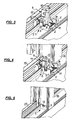
- FIGS. 6, 7 and 8 are different stages in the assembly of a post 16 with its two ends each shown on a frame support 15 and 17 made of plastic, as in the manufacturing process of a window frame 25 (see. Fig. 17 ) are present on a frame welding machine 18.
- FIG. 6 a side view of the post 16 with the two associated frame rails 15 and 17 after inserting the various frame parts in the frame welding machine
- Fig. 7 a longitudinal section through the arrangement Fig. 6 but in an already partially assembled intermediate stage
- Fig. 8 again a side view of the arrangement, but this time in final assembly state.
- a post connector 1 is already fastened by screws 11 to each of the two frame supports 15 and 17 shown.
- the post 16 is arranged in the frame welding machine so that the respective mold projection 4 of the associated post connector 1 protrudes to a certain extent already in the facing hollow profile of the post 16, in such a way that there the guide pin 12 already on the two flat sliding surfaces. 8 this shape projection 4 is applied.
- the frame welding machine is in this case in the extended position, d. H. the mounted on the frame welding frame profiles are spent in a remote position. Since in this position the mold projection 4 of each post connector 1 already protrudes into the hollow profile of the post 16 to be connected, it is ensured that the post 16 on the ends of the mold protrusions 4 already engaging at its ends in him under the support of his local guide pin 12 on the facing Sliding surfaces 8 is securely held and can not fall down.
- the sectional view of the Fig. 7 now shows an intermediate position during the assembly process, in which the distance between the two frame members 15 and 17 already against the position Fig. 6 reduced, but the final assembly position has not yet been reached.
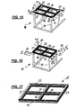
- a frame welding machine 18 which has a machine frame 19 which is provided at its upper end with four movable welding mirrors 20, each of which serves in the subsequent welding of a frame 25 for welding to a frame corner.
- Each welding mirror 20 is mounted so that it is at a desired miter angle, which is 45 ° in the illustrated embodiment, the individual mitred precut frame sections 15, 21, 22, 23 (see. Fig. 17 ) are heated at their abutting ends for welding.
- the welding mirrors 20 in the direction of arrow a (see. Fig. 15 ) between the frame corners to heat the facing end surfaces of the frame profiles for welding, after which the welding mirror 20 in the opposite direction a ' (see. Fig. 16 ) are driven outwards again.
- a frame profile 21 is first arranged on the machine frame 19 of the welding machine 18, as this Fig. 9 shows.
- a frame carrier is arranged centrally as a post 17, after which, approximately in the middle of the frame profiles 15 and 22, a further post 24, oriented perpendicular to these, is inserted (FIG. Fig. 12 ).
- Fig. 13 is illustrated, is still between the frame members 15 and 17, a post 16, aligned with the post 24, placed.
- the welding mirror 20 retracted in the feed direction (arrows a ) between the ends of the frame profiles 15, 21, 22 and 23, then this by the frame welding machine 18 moves toward each other so that their end faces abut against the welding mirror 20, after which the welding mirror 20 are heated and effect a corresponding heating of the voltage applied to them end surfaces of the frame profiles 15, 21, 22 and 23.
Landscapes
- Engineering & Computer Science (AREA)
- Civil Engineering (AREA)
- Structural Engineering (AREA)
- Mutual Connection Of Rods And Tubes (AREA)
- Lining Or Joining Of Plastics Or The Like (AREA)
- Connection Of Plates (AREA)
Applications Claiming Priority (1)
| Application Number | Priority Date | Filing Date | Title |
|---|---|---|---|
| DE102013223968.8A DE102013223968B4 (de) | 2013-11-22 | 2013-11-22 | Verbindungsanordnung zum Befestigen eines Pfostens an einem Rahmenträger eines Fensters, einer Türe oder dgl. aus Kunststoff |
Publications (1)
| Publication Number | Publication Date |
|---|---|
| EP2876242A1 true EP2876242A1 (fr) | 2015-05-27 |
Family
ID=51868769
Family Applications (1)
| Application Number | Title | Priority Date | Filing Date |
|---|---|---|---|
| EP14190304.7A Withdrawn EP2876242A1 (fr) | 2013-11-22 | 2014-10-24 | Système de liaison destiné à fixer un jambage à une poutre d'une fenêtre, d'une porte ou similaire en matière plastique |
Country Status (3)
| Country | Link |
|---|---|
| EP (1) | EP2876242A1 (fr) |
| DE (1) | DE102013223968B4 (fr) |
| RU (1) | RU2014146796A (fr) |
Families Citing this family (6)
| Publication number | Priority date | Publication date | Assignee | Title |
|---|---|---|---|---|
| DE102015112563A1 (de) | 2015-07-30 | 2017-02-02 | PHI Technik für Fenster und Türen GmbH | Verbindungsanordnung zum Verbinden eines Pfostens an einem Rahmenprofil eines Fensters oder einer Türe aus Kunststoff |
| DE102017122328A1 (de) | 2017-09-26 | 2019-03-28 | PHI Technik für Fenster und Türen GmbH | Verfahren und Verbindungsanordnung zum Verbinden eines Pfostens mit einem Rahmenprofil bei einem Fenster oder einer Türe aus Kunststoff |
| DE102018106525B4 (de) * | 2018-03-20 | 2025-06-05 | PHI Technik für Fenster und Türen GmbH | Verbindungsanordnung |
| DE202020107215U1 (de) | 2020-12-14 | 2022-03-15 | REHAU Industries SE & Co. KG | Verbinder zur mechanischen Verbindung von Rahmenprofile mit Pfosten-, Kämpfer- oder Sprossenprofilen im Fenster- und Türenbau sowie diesen umfassende Verbindung |
| DE102022102935B4 (de) | 2022-02-08 | 2024-08-22 | PHI Technik für Fenster und Türen GmbH | Verbindungsanordnung zum Verbinden eines Pfostens mit einem Rahmenprofil eines Fensters oder einer Türe aus Kunststoff |
| DE202022100722U1 (de) | 2022-02-08 | 2022-02-17 | PHI Technik für Fenster und Türen GmbH | Verbindungsanordnung zum Verbinden eines Pfostens mit einem Rahmenprofil eines Fensters oder einer Türe aus Kunststoff |
Citations (4)
| Publication number | Priority date | Publication date | Assignee | Title |
|---|---|---|---|---|
| DE9206625U1 (de) | 1992-05-15 | 1993-09-16 | Niemann, Hans Dieter, 50169 Kerpen | Verbindung für winklig aneinanderstoßende Hohlprofilstäbe |
| DE9316308U1 (de) | 1993-10-27 | 1995-02-23 | Niemann, Hans Dieter, 50169 Kerpen | Verbindungsstück für winklig aneinanderstoßende Rahmenstäbe |
| DE102010045809A1 (de) * | 2010-09-20 | 2012-03-22 | Hans Dieter Grotefeld | Verfahren und Vorrichtung zum Einsetzen eines Kämpfers in einen Tür- oder Fensterrahmen |
| DE202012008665U1 (de) | 2012-09-11 | 2012-10-26 | PHI Technik für Fenster und Türen GmbH | Anordnung zum Befestigen eines Pfostens an einer Rahmenleiste eines Fensters oder einer Türe mittels eines Pfostenverbinders |
-
2013
- 2013-11-22 DE DE102013223968.8A patent/DE102013223968B4/de active Active
-
2014
- 2014-10-24 EP EP14190304.7A patent/EP2876242A1/fr not_active Withdrawn
- 2014-11-21 RU RU2014146796A patent/RU2014146796A/ru not_active Application Discontinuation
Patent Citations (4)
| Publication number | Priority date | Publication date | Assignee | Title |
|---|---|---|---|---|
| DE9206625U1 (de) | 1992-05-15 | 1993-09-16 | Niemann, Hans Dieter, 50169 Kerpen | Verbindung für winklig aneinanderstoßende Hohlprofilstäbe |
| DE9316308U1 (de) | 1993-10-27 | 1995-02-23 | Niemann, Hans Dieter, 50169 Kerpen | Verbindungsstück für winklig aneinanderstoßende Rahmenstäbe |
| DE102010045809A1 (de) * | 2010-09-20 | 2012-03-22 | Hans Dieter Grotefeld | Verfahren und Vorrichtung zum Einsetzen eines Kämpfers in einen Tür- oder Fensterrahmen |
| DE202012008665U1 (de) | 2012-09-11 | 2012-10-26 | PHI Technik für Fenster und Türen GmbH | Anordnung zum Befestigen eines Pfostens an einer Rahmenleiste eines Fensters oder einer Türe mittels eines Pfostenverbinders |
Also Published As
| Publication number | Publication date |
|---|---|
| RU2014146796A (ru) | 2016-06-10 |
| DE102013223968A1 (de) | 2015-05-28 |
| DE102013223968B4 (de) | 2015-07-16 |
Similar Documents
| Publication | Publication Date | Title |
|---|---|---|
| DE102013223968B4 (de) | Verbindungsanordnung zum Befestigen eines Pfostens an einem Rahmenträger eines Fensters, einer Türe oder dgl. aus Kunststoff | |
| DE102012017948B3 (de) | Verfahren und Anordnung zum Befestigen eines Pfostens an einer Rahmenleiste eines Fensters oder einer Türe mittels eines Pfostenverbinders | |
| EP2233676A2 (fr) | Connecteur de rembourrage | |
| EP3031547B1 (fr) | Procede et dispositif de fabrication d'un raccord d'angle | |
| EP3124734B1 (fr) | Systeme de liaison destine a relier un jambage a un profil de cadre d'une fenetre ou d'une porte en matiere plastique | |
| EP3636844B1 (fr) | Cadre de construction en mur sec pour une porte coulissante | |
| DE102008015989B3 (de) | Schwellenhalter für Türrahmen | |
| EP2781678B1 (fr) | Guide de porte élévatrice/coulissante | |
| EP2760090A1 (fr) | Système de fixation et kit d'intégration pour le montage d'une passerelle de montage dans une armoire de commande | |
| DE102012000515A1 (de) | Rahmeneckverbindung für Fenster und/oder Türen | |
| DE3225049C2 (de) | Treibstangenverschluß | |
| EP2128372B1 (fr) | Fenêtre ou porte en matière plastique et son procédé de fabrication | |
| DE202009003438U1 (de) | Pfostenverbinder | |
| DE202012002574U1 (de) | Pfostenverbinder | |
| EP2947248B1 (fr) | Fenêtre, porte ou élément analogue pourvu d'un dispositif de centrage | |
| EP2679759B1 (fr) | Connecteur d'angle pour châssis en corps creux | |
| EP2354432B1 (fr) | Vantail d'une porte coulissante | |
| DE102012005295B3 (de) | Pfostenverbinder | |
| DE102012005091A1 (de) | Pfostenverbinder | |
| EP4407136B1 (fr) | Raccord d'angle avec élément d'expansion | |
| DE102006001045B4 (de) | Eckverbinder für Tür- oder Fensterrahmen | |
| DE102014100688A1 (de) | Profilverbinder | |
| DE202008004218U1 (de) | Schwellenhalter für Türrahmen | |
| DE202012002712U1 (de) | Pfostenverbinder | |
| DE2202599C3 (de) | Eckumlenkung für Treibstangen an Dreh-Kipp-Fenstern oder -Türen |
Legal Events
| Date | Code | Title | Description |
|---|---|---|---|
| PUAI | Public reference made under article 153(3) epc to a published international application that has entered the european phase |
Free format text: ORIGINAL CODE: 0009012 |
|
| 17P | Request for examination filed |
Effective date: 20141024 |
|
| AK | Designated contracting states |
Kind code of ref document: A1 Designated state(s): AL AT BE BG CH CY CZ DE DK EE ES FI FR GB GR HR HU IE IS IT LI LT LU LV MC MK MT NL NO PL PT RO RS SE SI SK SM TR |
|
| AX | Request for extension of the european patent |
Extension state: BA ME |
|
| STAA | Information on the status of an ep patent application or granted ep patent |
Free format text: STATUS: THE APPLICATION IS DEEMED TO BE WITHDRAWN |
|
| 18D | Application deemed to be withdrawn |
Effective date: 20151128 |