EP2876247B1 - Synchroniseur de volume pour des outils de manipulation de matériel tubulaire - Google Patents
Synchroniseur de volume pour des outils de manipulation de matériel tubulaire Download PDFInfo
- Publication number
- EP2876247B1 EP2876247B1 EP14193437.2A EP14193437A EP2876247B1 EP 2876247 B1 EP2876247 B1 EP 2876247B1 EP 14193437 A EP14193437 A EP 14193437A EP 2876247 B1 EP2876247 B1 EP 2876247B1
- Authority
- EP
- European Patent Office
- Prior art keywords
- chambers
- fluid
- piston
- handling tool
- tubular
- Prior art date
- Legal status (The legal status is an assumption and is not a legal conclusion. Google has not performed a legal analysis and makes no representation as to the accuracy of the status listed.)
- Not-in-force
Links
Images

Classifications
-
- E—FIXED CONSTRUCTIONS
- E21—EARTH OR ROCK DRILLING; MINING
- E21B—EARTH OR ROCK DRILLING; OBTAINING OIL, GAS, WATER, SOLUBLE OR MELTABLE MATERIALS OR A SLURRY OF MINERALS FROM WELLS
- E21B44/00—Automatic control systems specially adapted for drilling operations, i.e. self-operating systems which function to carry out or modify a drilling operation without intervention of a human operator, e.g. computer-controlled drilling systems; Systems specially adapted for monitoring a plurality of drilling variables or conditions
- E21B44/02—Automatic control of the tool feed
-
- E—FIXED CONSTRUCTIONS
- E21—EARTH OR ROCK DRILLING; MINING
- E21B—EARTH OR ROCK DRILLING; OBTAINING OIL, GAS, WATER, SOLUBLE OR MELTABLE MATERIALS OR A SLURRY OF MINERALS FROM WELLS
- E21B19/00—Handling rods, casings, tubes or the like outside the borehole, e.g. in the derrick; Apparatus for feeding the rods or cables
-
- E—FIXED CONSTRUCTIONS
- E21—EARTH OR ROCK DRILLING; MINING
- E21B—EARTH OR ROCK DRILLING; OBTAINING OIL, GAS, WATER, SOLUBLE OR MELTABLE MATERIALS OR A SLURRY OF MINERALS FROM WELLS
- E21B19/00—Handling rods, casings, tubes or the like outside the borehole, e.g. in the derrick; Apparatus for feeding the rods or cables
- E21B19/10—Slips; Spiders ; Catching devices
-
- F—MECHANICAL ENGINEERING; LIGHTING; HEATING; WEAPONS; BLASTING
- F15—FLUID-PRESSURE ACTUATORS; HYDRAULICS OR PNEUMATICS IN GENERAL
- F15B—SYSTEMS ACTING BY MEANS OF FLUIDS IN GENERAL; FLUID-PRESSURE ACTUATORS, e.g. SERVOMOTORS; DETAILS OF FLUID-PRESSURE SYSTEMS, NOT OTHERWISE PROVIDED FOR
- F15B11/00—Servomotor systems without provision for follow-up action ; Circuits therefor
- F15B11/16—Servomotor systems without provision for follow-up action ; Circuits therefor with two or more servomotors
- F15B11/22—Synchronisation of the movement of two or more servomotors
-
- F—MECHANICAL ENGINEERING; LIGHTING; HEATING; WEAPONS; BLASTING
- F15—FLUID-PRESSURE ACTUATORS; HYDRAULICS OR PNEUMATICS IN GENERAL
- F15B—SYSTEMS ACTING BY MEANS OF FLUIDS IN GENERAL; FLUID-PRESSURE ACTUATORS, e.g. SERVOMOTORS; DETAILS OF FLUID-PRESSURE SYSTEMS, NOT OTHERWISE PROVIDED FOR
- F15B11/00—Servomotor systems without provision for follow-up action ; Circuits therefor
- F15B11/08—Servomotor systems without provision for follow-up action ; Circuits therefor with only one servomotor
- F15B11/12—Servomotor systems without provision for follow-up action ; Circuits therefor with only one servomotor providing distinct intermediate positions; with step-by-step action
- F15B11/13—Servomotor systems without provision for follow-up action ; Circuits therefor with only one servomotor providing distinct intermediate positions; with step-by-step action using separate dosing chambers of predetermined volume
-
- F—MECHANICAL ENGINEERING; LIGHTING; HEATING; WEAPONS; BLASTING
- F15—FLUID-PRESSURE ACTUATORS; HYDRAULICS OR PNEUMATICS IN GENERAL
- F15B—SYSTEMS ACTING BY MEANS OF FLUIDS IN GENERAL; FLUID-PRESSURE ACTUATORS, e.g. SERVOMOTORS; DETAILS OF FLUID-PRESSURE SYSTEMS, NOT OTHERWISE PROVIDED FOR
- F15B2211/00—Circuits for servomotor systems
- F15B2211/40—Flow control
- F15B2211/405—Flow control characterised by the type of flow control means or valve
-
- F—MECHANICAL ENGINEERING; LIGHTING; HEATING; WEAPONS; BLASTING
- F15—FLUID-PRESSURE ACTUATORS; HYDRAULICS OR PNEUMATICS IN GENERAL
- F15B—SYSTEMS ACTING BY MEANS OF FLUIDS IN GENERAL; FLUID-PRESSURE ACTUATORS, e.g. SERVOMOTORS; DETAILS OF FLUID-PRESSURE SYSTEMS, NOT OTHERWISE PROVIDED FOR
- F15B2211/00—Circuits for servomotor systems
- F15B2211/70—Output members, e.g. hydraulic motors or cylinders or control therefor
- F15B2211/71—Multiple output members, e.g. multiple hydraulic motors or cylinders
-
- F—MECHANICAL ENGINEERING; LIGHTING; HEATING; WEAPONS; BLASTING
- F15—FLUID-PRESSURE ACTUATORS; HYDRAULICS OR PNEUMATICS IN GENERAL
- F15B—SYSTEMS ACTING BY MEANS OF FLUIDS IN GENERAL; FLUID-PRESSURE ACTUATORS, e.g. SERVOMOTORS; DETAILS OF FLUID-PRESSURE SYSTEMS, NOT OTHERWISE PROVIDED FOR
- F15B2211/00—Circuits for servomotor systems
- F15B2211/70—Output members, e.g. hydraulic motors or cylinders or control therefor
- F15B2211/78—Control of multiple output members
- F15B2211/782—Concurrent control, e.g. synchronisation of two or more actuators
Definitions
- Embodiments of the invention generally relate to a control system for synchronizing the supply of a volume of fluid to a tubular handling tool.
- spiders and elevators include a plurality of slips that are disposed about the inner circumference of a housing, also known as a bowl.
- the slips include teeth that grip the tubular string.
- the inner surface of the housing is inclined so that the slips may be moved downwardly and radially inward into engagement with the tubular string, and may be moved upwardly and radially outward out of engagement with the tubular string.
- US6089338 discloses a spider and slip assembly for manipulating pipe strings.
- slips engage the tubular string uniformly about its circumference.
- the slips are generally positioned symmetrically around the tubular string. However, as the slips are moved into engagement with the tubular string, one slip may contact the tubular before another slip, and thereby move the tubular string into a slightly off-center position.
- a control system comprising a fluid source; a tubular handling tool having a plurality of piston cylinders and a plurality of slips configured to engage a tubular string; and a volume synchronizer.
- the volume synchronizer comprises a plurality of first chambers in fluid communication with the fluid source; a plurality of second chambers in fluid communication with the piston cylinders; a piston separating each of the first and second chambers; and a rod member connected to each piston. Pressurized fluid supplied to the first chambers simultaneously moves each of the pistons to simultaneously force pressurized fluid out of the second chambers and into the piston cylinders of the tubular handling tool to actuate the slips into engagement with the tubular string.
- Each of the piston cylinders of the tubular handling tool includes a piston separating a first chamber from a second chamber of the piston cylinder.
- a valve is configured to control fluid communication between the fluid source and the first chambers of the volume synchronizer, and between the fluid source and the second chambers of the piston cylinders.
- a control system comprising a tubular handling tool having a plurality of piston cylinders and a plurality of slips configured to engage a tubular string; and a volume synchronizer.
- the volume synchronizer comprises a first piston cylinder having a piston connected to a first rod member; a plate member connected to the first rod member; and a plurality of second piston cylinders, each having pistons connected to the plate member by a plurality of second rod members. Pressurized fluid supplied to the first piston cylinder moves the plate member to move each of the pistons in the second piston cylinders to simultaneously force pressurized fluid out of the second piston cylinders and into the piston cylinders of the tubular handling tool to actuate the slips into engagement with the tubular string.
- a method of actuating a tubular handling tool comprises supplying pressurized fluid to a plurality of first chambers of a volume synchronizer, each of the first chambers being separated from a second chamber by a piston, each of the pistons being connected together by a rod member; simultaneously supplying a substantially equal amount of pressurized fluid from each of the second chambers to a plurality of piston cylinders of the tubular handling tool; wherein each of the piston cylinders of the tubular handing tool includes a piston separating a first chamber and a second chamber of the piston cylinder, each piston coupled to a slip by a rod member; simultaneously actuating slips of the tubular handling tool into engagement with a tubular string and actuating a valve that controls fluid communication between a fluid source and the first chambers of the volume synchronizer, and between the fluid source and the second chambers of the piston cylinders.
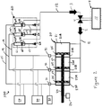
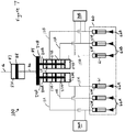
- Figure 1 illustrates a control system 100 for controlling the operation of a tubular handling tool 60.
- the control system 100 controls the supply of fluid to a plurality of piston cylinders 61 to synchronize the actuation of a plurality of slips 66 of the tubular handing tool 60.
- the tubular handling tool 60 may include any type of spider, elevator, tong, and/or articulating arm device known in the art.
- One example of a tubular handling tool 60 is the wedge device 1 disclosed in U.S. Patent No. 7,980,298 .
- Another example of a tubular handling tool 60 is the apparatus 101 having arms 109, 114, 115 disclosed in U.S. Patent No. 6,591,471 .
- the control system 100 may be configured to control the operation of other fluid actuated tools known in the art.
- the control system 100 includes a control unit 4 comprising a fluid source 10 configured to supply and receive fluid to and from the tubular handling tool 60 and a volume synchronizer 20.
- the control unit 4 may comprise one or more control panels (including key pads, switches, knobs, touch pads, etc.), valves, and/or additional control and fluid lines configured to communicate with, monitor, and control the operation of the components of the control system 100, including valve 5, volume synchronizer 20, tubular handling tool 60, sensors 26, 31, relieve valve 30, fluid inlet 40, and fluid outlet 50.
- the control unit 4 may be equipped with a programmable central processing unit, a memory, a mass storage device, and well-known support circuits such as power supplies, clocks, cache, input/output circuits and the like.
- the control unit 4 may actuate a valve 5, such as a solenoid valve, that controls the flow of fluid to and from the tubular handling tool 60 and the volume synchronizer 20.
- a valve 5 such as a solenoid valve
- fluid from (first) chambers 21A, 22A, 23A of the volume synchronizer 20 is returned to the fluid source 10 via fluid line 11.
- fluid from the fluid source 10 is supplied to (second) chambers 61B, 62B, 63B of the piston cylinders 61 of the tubular handling tool 60 via fluid line 12.
- Each slip 66 of the tubular handling tool 60 is connected to a piston 65 disposed in each piston cylinder 61 by a rod member 64.
- Pressurized fluid supplied to the chambers 61B, 62B, 63B moves the pistons 65 to move the slips 66 in unison into a first position, such as a retracted or open position where the slips 66 do not engage a tubular string disposed in or adjacent the tubular handling tool 60.
- the pistons 65 force fluid out of (first) chambers 61 , 62A, 63A and into the fluid lines 13, 14, 15 that are respectively connected to each chamber.
- the fluid lines 13, 14, 15 are in fluid communication with (second) chambers 21B, 22B, 23B of the volume synchronizer 20.
- the volume synchronizer 20 includes a body, such as a piston cylinder, having one or more chambers. As illustrated, three chambers 21, 22, 23 are fluidly isolated from each other. A piston 25 is disposed in each chamber 21, 22, 23, separating first chambers 21A, 22A, 23A and second chambers 21B, 22B, 23B. Each piston 25 is coupled to a single rod member 24 so that all of the pistons 25 move in unison, e.g. together as a unit. The rod member 24 is movable and extends through one or more of the chambers 21, 22, 23 and out of the body of the volume synchronizer 20.
- One or more seals may be disposed between the rod member 24 and the body of volume synchronizer 20 to prevent leakage out of the body and between the chambers 21, 22, 23.
- the pistons 25 are coupled to the rod member 24 and positioned within the chambers 21, 22, 23 such that the chambers 21A, 22A, 23A have substantially equal volumes, and such that the chambers 21B, 22B, 23B also have substantially equal volumes.
- one or more of the chambers 21A, 22A, 23A and/or 21B, 22B, 23B may have substantially different volumes than the other chambers.
- the volume synchronizer 20 may be positioned adjacent to or within the control unit 4 and/or fluid source 10. In other embodiments, the volume synchronizer 20 may be positioned adjacent to or within the tubular handling tool 60, or at any other location between the tubular handling tool 60 and the control unit 4 and/or fluid source 10.
- the pistons 25 force fluid out of the chambers 21A, 22A, 23A and into the fluid line 11 that is connected to each chamber 21A, 22A, 23A.
- the fluid in the fluid line 11 is returned to the fluid source 10 through the valve 5 as illustrated by reference arrow 2 in Figure 1 .
- the fluid lines 13, 14, 15 provide fluid communication between chambers 21B, 22B, 23B of the volume synchronizer 20 and chambers 63A, 62A, 61A, respectively, of the piston cylinders 61 of the tubular handling tool 60. Although illustrated as having different lengths, each of the fluid lines 13, 14, 15 may have substantially the same length.
- the volume synchronizer 20 via the fluid lines 13, 14, 15 synchronizes the timing and amount of pressurized fluid that is supplied to each piston cylinder 61 of the tubular handling tool 60 to synchronize the actuation of the slips 66.
- a relief valve 30 may be in fluid communication with the fluid lines 13, 14, 15 to release fluid from the lines in the event that the pressure in the fluid lines 13, 14, 15 exceeds a predetermined amount.
- One or more sensors 31, such as pressure transducers, may be coupled to each line to measure and monitor the pressure in the fluid lines 13, 14, 15. In one embodiment, one or more of the sensors 31 may measure and monitor the amount of fluid flow out of the chambers 21B, 22B, 23B, into the chambers 61A, 62A, 63A, and/or through at least a portion of the fluid lines 13, 14, 15.
- the sensors 31 may be positioned near the outlet of the chambers 21B, 22B, 23B, near the inlet of the chambers 61A, 62A, 63A, and/or at any other intermediate location along the fluid lines 13, 14, 15.
- a fluid inlet 40 having one or more valves that may be used to fill or refill the fluid lines 13, 14, 15, the pistons 61, and/or the volume synchronizer 20 with fluid, e.g. liquid or gas.
- a fluid outlet 50 having one or more valves that may be used to remove or bleed fluid, e.g. liquid or gas, from the fluid lines 13, 14, 15, the pistons 61, and/or the volume synchronizer 20.
- a sensor 26 may be used to measure and monitor the position of the rod member 24 to provide an indication of the operational position of the volume synchronizer 20.
- the sensor 26 may include a position indicator contacting the rod member 24 to continuously measure and monitor the exact location of the rod member 24, thereby providing an indication of the operational position of the volume synchronizer 20.
- the sensor 26 may include one or more position sensors arranged to measure and monitor discrete positions (such as an initial, intermediate, and/or final position) of the rod member 24, thereby providing an indication of the operational position of the volume synchronizer 20.
- fluid from the fluid source 10 is supplied to chambers 21A, 22A, 23A of the volume synchronizer 20 via fluid line 11.
- Pressurized fluid supplied to the chambers 21A, 22A, 23A moves the pistons 25 and the rod member 24 in unison into a second position, such as an extended or closed position.
- the pistons 25 force pressurized fluid out of the chambers 21B, 22B, 23B and into the fluid line 13, 14, 15 that is connected to each chamber.
- the pressurized fluid from each fluid line 13, 14, 15 is supplied to each chamber 63A, 62A, 61A, respectively, of the pistons 61 of the tubular handling tool 60.
- Pressurized fluid supplied to the chambers 63A, 62A, 61A moves the pistons 65 to move the slips 66 in unison into a second position, such as an extended or closed position where the slips 66 engage a tubular string disposed in or adjacent the tubular handling tool 60.
- the pistons 65 force fluid out of the chambers 61B, 62B, 63B and into the fluid line 12 that is connected to each chamber.
- the fluid in the fluid line 12 is returned to the fluid source 10 through the valve 5 as illustrated by reference arrow 3 in Figure 2 .
- the volume synchronizer 20 is configured to simultaneously supply a substantially equal amount of fluid to each piston 61 of the tubular handling tool 60 to synchronize the movement of the slips 66 into engagement with a tubular string.
- the slips 66 may be uniformly positioned around the tubular string. Actuation of by the slips 66 using the volume synchronizer 20 will ensure that the tubular is properly engaged and supported by the slips 66 of the tubular handling tool 60.
- the rod member 24 may engage the sensor 26.
- the sensor 26 may provide verification that the tubular handling tool 60 has been actuated into a fully closed position by the volume synchronizer 20.
- contact between the rod member 24 and the sensor 26 may provide an indication that the pistons 25 in the volume synchronizer 20 have moved a distance sufficient to force a predetermined amount of pressurized fluid into the chambers 61A, 62A, 63A of the tubular handling tool 60 to actuate the slips 66.
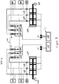
- Figure 3 illustrates the control system 100 controlling the actuation of two (first and second) sets of slips 66A, 66B of a tubular handling tool 60 via two volume synchronizers 20A, 20B.
- the control unit 4 may include two fluid sources 10A, 10B, or may include a single fluid source, configured to supply fluid to the volume synchronizers 20A, 20B and receive fluid from the piston cylinders 61 of the tubular handling tool 60.
- the control unit 4 may be configured to communicate with, monitor, and control the operation of the components of the control system 100, including valves 5A, 5B, volume synchronizers 20A, 20B, tubular handling tool 60, sensors 26A, 26B, 31A, 31B, relieve valves 30A, 30B, fluid inlets 40A, 40B, and fluid outlets 50A, 50B.
- control system 100 may be configured to synchronize the actuation of only the slips 66A to grip and support a tubular string having one outer diameter size, and configured to synchronize the actuation of only the slips 66B to grip and support a tubular string having different outer diameter size.
- the slips 66A may be configured to grip and support tubular strings within one range of outer diameter sizes, while the slips 66B may be configured to grip and support tubular strings within a different range of outer diameter sizes.
- the control system 100 may be configured to synchronize the actuation of all six slips 66A, 66B simultaneously to grip and support a tubular string.
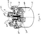
- FIG. 4 illustrates one embodiment of the tubular handling tool 60.
- the tubular handling tool 60 includes the plurality of slips 66A, 66B, each having gripping surfaces 7 for engaging a tubular string disposed along or adjacent the central axis 1 of the tubular handling tool 60.
- the piston cylinders 61 are configured to extend and retract the slips 66A, 66B into and out of engagement with the tubular string.
- the slips 66A, 66B are supported by support members 68, which are coupled to a housing 69, also known as a bowl, of the tubular handling tool 60.
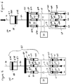
- Figures 5 and 6 illustrate a further control system 100.
- One or more of the components of the control system 100 illustrated in Figures 1 , 2 , 3 , and 4 may be used with the control system 100 illustrated in Figures 5 and 6 . Similar components may be identified with the same reference numerals.
- Figure 5 illustrates a volume synchronizer 80 configured to synchronize the supply of substantially equal amounts of fluid to the piston cylinders 61 of the tubular handling tool 60.
- the volume synchronizer 80 includes three piston cylinders 81 having chambers 83B, 82B, 81B that are in fluid communication with chambers 63A, 62A, 61A of the three piston cylinders 61 of the tubular handling tool 60 via fluid lines 13, 14, 15, respectively.
- the volume synchronizer 80 and the tubular handling tool 60 may be configured with one, two, three, or more piston cylinders.
- One or more control valves 70 may be used to provide fluid communication to the fluid lines 13, 14, 15.
- the control valve 70 may operate similar to the relief valve 30, the fluid inlet 40, and/or the fluid outlet 50.
- the control valve 70 may be configured to relieve, fill, and/or remove fluid from, as well as monitor the fluid pressure in, the fluid lines 13, 14, 15, the chambers 83B, 82B, 81B, and/or the chambers 63A, 62A, 61A.
- a piston 85 may be disposed in each piston cylinder 81, and each piston 85 may be connected to a plate member 84 via rod members 89.
- the plate member 84 also may be connected to a piston 88 disposed in another piston cylinder 87 by a rod member 86. Any number of rod members 86, 89 may be used.
- a chamber 87A of the piston cylinder 87 may be in fluid communication with a fluid line 16.
- the fluid line 16 may supply pressurized fluid to the chamber 87A from a fluid source, such as the fluid source 10 of the control unit 4 illustrated in Figures 1 and 2 .
- the volume synchronizer 80 and the tubular handling tool 60 may be in a first position, such as a retracted or open position, where the slips 66 do not engage a tubular string disposed in or adjacent the tubular handling tool 60.
- the volume synchronizer 80 and the tubular handling tool 60 may be in a second position, such as an extended or closed position, where the slips 66 engage a tubular string disposed in or adjacent the tubular handling tool 60.
- pressurized fluid (such as from the fluid source 10) is supplied to chamber 87A via fluid line 16 to move the piston 88 and the rod member 86 in a direction toward the piston cylinders 81.
- the rod member 86 moves the plate member 84, and at the same time, moves the pistons 85 via rod members 89 in unison to force pressurized fluid out of the chambers 81B, 82B, 83B and into the fluid line 13, 14, 15 that is connected to each chamber.
- the pressurized fluid from each fluid line 13, 14, 15 is supplied to each chamber 63A, 62A, 61A, respectively, of the pistons 61 of the tubular handling tool 60 to actuate the slips 66 in unison.
- Pressurized fluid supplied to the chambers 63A, 62A, 61A moves the pistons 65 to move the slips 66 in unison into the second position, such as the extended or closed position where the slips 66 engage a tubular string disposed in or adjacent the tubular handling tool 60.
- the pistons 65 may compress and/or force fluid out of the chambers 61B, 62B, 63B, which fluid may be returned to the fluid source 10 for example.
- pressurized fluid may be supplied into the chambers 61B, 62B, 63B to retract the slips 66 in unison and move the tubular handling tool 60 and the volume synchronizer 80 back into the first position, such as the retracted or open position.
- the chambers 81A, 82A, 83A may be empty or may include a compressible fluid.
- the volume synchronizer 80 is configured to simultaneously supply substantially equal amount of fluid to each piston cylinder 61 of the tubular handling tool 60 to synchronize the movement of the slips 66 into engagement with a tubular string.
- the slips 66 may be uniformly positioned around the tubular string. Actuation of the slips 66 using the volume synchronizer 20 will ensure that the tubular string is properly engaged and supported by the slips 66 of the tubular handling tool 60.
- the control system 100 may include a plurality of volume synchronizers 80.
- One volume synchronizer 80 may be configured to supply pressurized fluid only to a first set of piston cylinders 61 having slips 66A, and another volume synchronizer 80 may be configured to supply pressurized fluid only to a second set of piston cylinders 61 having slips 66B of the tubular handling tool 60 illustrated in Figure 4 .
- Figure 7 illustrate a further control system 100.
- One or more of the components of the control systems 100 illustrated in Figures 1 , 2 , 3 , 4 , 5, and 6 may be used with the control system 100 illustrated in Figure 7 . Similar components may be identified with the same reference numerals.
- pressurized fluid (such as from the fluid source 10 of control unit 4) is supplied to chamber 87A via fluid line 16 to move the piston 88 and the rod member 86 in a direction toward volume synchronizers 20A, 20B (e.g. piston cylinders).
- the rod member 86 moves the plate member 84, and at the same time, moves the pistons 25 via rod members 24A, 24B in unison to force pressurized fluid out of the chambers 27A, 27B and into the fluid line 13A, 13B, 14A, 14B, 15A, 15B that is connected to each chamber.
- each fluid line 13A, 13B, 14A, 14B, 15A, 15B is supplied to each chamber 67A, 67B, respectively, of the pistons 61 of the tubular handling tool 60 to actuate the slips 66A, 66B in unison.
- the control valves 70A, 70B may be configured to relieve, fill, and/or remove fluid from, as well as monitor the fluid pressure in, the fluid lines 13A, 13B, 14A, 14B, 15A, 15B and the chambers 67A, 67B, respectively.
- only one volume synchronizer 20A or 20B may be used to supply fluid to each of the chambers 67A, 67B.
- the one volume synchronizer 20A or 20B may include six chambers configured to supply fluid to the six piston cylinders 61 of the tubular handling tool 60.
- the one volume synchronizer 20A or 20B may include three chambers, each chamber configured to supply fluid to at least two chambers 67A, 67B of the piston cylinders 61 of the tubular handling tool 60.
Landscapes
- Engineering & Computer Science (AREA)
- Mining & Mineral Resources (AREA)
- Life Sciences & Earth Sciences (AREA)
- Geology (AREA)
- Physics & Mathematics (AREA)
- Fluid Mechanics (AREA)
- Mechanical Engineering (AREA)
- General Life Sciences & Earth Sciences (AREA)
- Geochemistry & Mineralogy (AREA)
- Environmental & Geological Engineering (AREA)
- General Engineering & Computer Science (AREA)
- Earth Drilling (AREA)
- Fluid-Pressure Circuits (AREA)
- Shaping Metal By Deep-Drawing, Or The Like (AREA)
Claims (9)
- Système de commande (100), comprenant :une source de fluide (10) ;un outil de manipulation tubulaire (60) qui comporte une pluralité de cylindres à piston (61) et une pluralité de moyens de préhension à glissement (66) qui sont configurés de manière à engager une colonne tubulaire ;un synchroniseur de volume (20) comprenant :une pluralité de premières chambres (21A, 22A, 23A) en communication de fluide avec la source de fluide ;une pluralité de secondes chambres (21B, 22B, 23B) en communication de fluide avec les cylindres à piston ;un piston (25) qui sépare chacune des premières et secondes chambres ; etun élément de tige (24) qui est connecté à chaque piston,dans lequel :un fluide sous pression qui est alimenté sur les premières chambres déplace de manière simultanée chacun des pistons, ce qui a pour effet de forcer le fluide sous pression hors des secondes chambres et de manière simultanée, à l'intérieur des cylindres à piston de l'outil de manipulation tubulaire, ce qui actionne par voie de conséquence les moyens de préhension à glissement pour les amener en engagement avec la colonne tubulaire ;chacun des cylindres à piston de l'outil de manipulation tubulaire inclut un piston (65) qui sépare une première chambre (61A, 62A, 63A) d'une seconde chambre (61B, 62B, 63B) du cylindre à piston ; etle système de commande comprend en outre une vanne (5) qui est configurée de manière à contrôler une communication de fluide entre la source de fluide et les premières chambres du synchroniseur de volume ainsi qu'entre la source de fluide et les secondes chambres des cylindres à piston.
- Système de commande selon la revendication 1, dans lequel une quantité de fluide sensiblement égale est alimentée depuis chacune des secondes chambres du synchroniseur de volume jusqu'à chacun des cylindres à piston de manière à déplacer les moyens de préhension à glissement à l'unisson et en engagement avec la colonne tubulaire.
- Système de commande selon la revendication 1 ou 2, dans lequel chacune des secondes chambres du synchroniseur de volume est en communication de fluide avec seulement l'une des premières chambres des cylindres à piston, dans lequel chacune des premières chambres des cylindres à piston est en communication de fluide avec seulement l'une des secondes chambres du synchroniseur de volume.
- Système de commande selon l'une quelconque des revendications précédentes, comprenant en outre un capteur qui est configuré de manière à fournir une indication d'une position de l'élément de tige du synchroniseur de volume.
- Système de commande selon l'une quelconque des revendications précédentes, dans lequel l'outil de manipulation tubulaire comprend un outil de repêchage/une araignée, un élévateur, une clé à tige(s) ou un dispositif de bras articulé.
- Procédé d'actionnement d'un outil de manipulation tubulaire (60), comprenant :l'alimentation de fluide sous pression sur une pluralité de premières chambres (21A, 22A, 23A) d'un synchroniseur de volume (20), chacune des premières chambres étant séparée d'une seconde chambre (21B, 22B, 23B) par un piston (25), chacun des pistons étant connecté en association au moyen d'un élément de tige (24) ;l'alimentation de manière simultanée d'une quantité de fluide sous pression sensiblement égale depuis chacune des secondes chambres jusqu'à une pluralité de cylindres à piston (61) de l'outil de manipulation tubulaire, dans lequel chacun des cylindres à piston de l'outil de manipulation tubulaire inclut un piston (65) qui sépare une première chambre (61A, 62A, 63A) et une seconde chambre (61B, 62B, 63B) du cylindre à piston, chaque piston étant couplé à un moyen de préhension à glissement (66) au moyen d'un élément de tige (64) ;l'actionnement de manière simultanée de moyens de préhension à glissement de l'outil de manipulation tubulaire pour les amener en engagement avec une colonne tubulaire ; etl'actionnement d'une vanne (5) qui contrôle une communication de fluide entre une source de fluide (10) et les premières chambres du synchroniseur de volume ainsi qu'entre la source de fluide et les secondes chambres des cylindres à piston.
- Procédé selon la revendication 6, comprenant en outre l'alimentation de manière simultanée de fluide sous pression depuis chacune des secondes chambres du synchroniseur de volume jusqu'à chacune des premières chambres des cylindres à piston et le retour du fluide depuis les secondes chambres des cylindres à piston jusqu'à une source de fluide.
- Procédé selon la revendication 7, comprenant en outre l'alimentation de fluide sous pression depuis la source de fluide jusqu'à la pluralité de premières chambres du synchroniseur de volume.
- Procédé selon la revendication 8, comprenant en outre l'actionnement d'un premier jeu de moyens de préhension à glissement de l'outil de manipulation tubulaire en utilisant le synchroniseur de volume et l'actionnement d'un second jeu de moyens de préhension à glissement de l'outil de manipulation tubulaire en utilisant un autre synchroniseur de volume.
Priority Applications (1)
| Application Number | Priority Date | Filing Date | Title |
|---|---|---|---|
| EP16202438.4A EP3168411B1 (fr) | 2013-11-26 | 2014-11-17 | Synchroniseur de volume pour outils de manipulation de matériel tubulaire |
Applications Claiming Priority (1)
| Application Number | Priority Date | Filing Date | Title |
|---|---|---|---|
| US14/091,230 US9528363B2 (en) | 2013-11-26 | 2013-11-26 | Volume synchronizer for tubular handling tools |
Related Child Applications (2)
| Application Number | Title | Priority Date | Filing Date |
|---|---|---|---|
| EP16202438.4A Division EP3168411B1 (fr) | 2013-11-26 | 2014-11-17 | Synchroniseur de volume pour outils de manipulation de matériel tubulaire |
| EP16202438.4A Division-Into EP3168411B1 (fr) | 2013-11-26 | 2014-11-17 | Synchroniseur de volume pour outils de manipulation de matériel tubulaire |
Publications (3)
| Publication Number | Publication Date |
|---|---|
| EP2876247A2 EP2876247A2 (fr) | 2015-05-27 |
| EP2876247A3 EP2876247A3 (fr) | 2016-07-27 |
| EP2876247B1 true EP2876247B1 (fr) | 2017-09-20 |
Family
ID=52006818
Family Applications (2)
| Application Number | Title | Priority Date | Filing Date |
|---|---|---|---|
| EP16202438.4A Not-in-force EP3168411B1 (fr) | 2013-11-26 | 2014-11-17 | Synchroniseur de volume pour outils de manipulation de matériel tubulaire |
| EP14193437.2A Not-in-force EP2876247B1 (fr) | 2013-11-26 | 2014-11-17 | Synchroniseur de volume pour des outils de manipulation de matériel tubulaire |
Family Applications Before (1)
| Application Number | Title | Priority Date | Filing Date |
|---|---|---|---|
| EP16202438.4A Not-in-force EP3168411B1 (fr) | 2013-11-26 | 2014-11-17 | Synchroniseur de volume pour outils de manipulation de matériel tubulaire |
Country Status (5)
| Country | Link |
|---|---|
| US (1) | US9528363B2 (fr) |
| EP (2) | EP3168411B1 (fr) |
| AU (2) | AU2014265131B2 (fr) |
| CA (1) | CA2871397C (fr) |
| NO (1) | NO3038879T3 (fr) |
Families Citing this family (15)
| Publication number | Priority date | Publication date | Assignee | Title |
|---|---|---|---|---|
| US9528363B2 (en) * | 2013-11-26 | 2016-12-27 | Weatherford Technology Holdings, Llc | Volume synchronizer for tubular handling tools |
| AU2014397698B2 (en) * | 2014-06-18 | 2018-12-20 | Aw-Energy Oy | Wave energy recovery apparatus with an energy transfer arrangement |
| WO2016061539A1 (fr) | 2014-10-17 | 2016-04-21 | Vehicle Service Group, Llc | Synchroniseur hydraulique |
| CN106015159B (zh) * | 2016-07-12 | 2019-01-18 | 天津优瑞纳斯液压机械有限公司 | 一种非等容积同步分配器液压缸 |
| US10774600B2 (en) | 2016-08-19 | 2020-09-15 | Weatherford Technology Holdings, Llc | Slip monitor and control |
| CN106224311A (zh) * | 2016-09-19 | 2016-12-14 | 南通市腾达锻压机床厂 | 专用控制两油缸同步的同步缸 |
| CN106438535A (zh) * | 2016-10-18 | 2017-02-22 | 浙江佳合文化科技股份有限公司 | 多向等速分流液压缸 |
| CN106678112B (zh) * | 2016-12-27 | 2018-04-27 | 武汉船用机械有限责任公司 | 一种水下油缸控制系统 |
| CN107314000A (zh) * | 2017-06-22 | 2017-11-03 | 马鞍山钢铁股份有限公司 | 基于连铸中间包升降液压缸同步控制系统的同步控制方法 |
| US10392878B2 (en) * | 2017-07-10 | 2019-08-27 | Caterpillar Global Mining Equipment Llc | Control system for actuating drill pipe rack |
| CN107165875B (zh) * | 2017-07-20 | 2019-01-25 | 马鞍山钢铁股份有限公司 | 一种型钢冷床步进梁平移液压缸同步控制方法 |
| CN108127560A (zh) * | 2017-12-08 | 2018-06-08 | 中国兵器科学研究院宁波分院 | 用于方形光学元件双面快速抛光的控制系统 |
| CN109578353B (zh) * | 2018-11-29 | 2020-07-31 | 重庆邮电大学 | 一种同步误差自动清零液压控制回路 |
| CN115025905B (zh) * | 2022-05-30 | 2023-06-23 | 杭州泛亚卫浴股份有限公司 | 一种管类装载结构 |
| WO2026159496A1 (fr) * | 2025-01-21 | 2026-07-30 | Weatherford Technology Holdings, Llc | Actionnement de coins de retenue à étages multiples destiné à être utilisé avec un puits souterrain |
Family Cites Families (19)
| Publication number | Priority date | Publication date | Assignee | Title |
|---|---|---|---|---|
| US2351887A (en) | 1943-05-10 | 1944-06-20 | Shell Dev | Power-actuated spider and slips |
| US3643725A (en) * | 1969-05-15 | 1972-02-22 | William L Fismer | Method for lifting flasks and molds |
| GB1568086A (en) * | 1976-03-05 | 1980-05-21 | Kosmala R | Hydraulic devices |
| US4161229A (en) * | 1977-05-31 | 1979-07-17 | Exxon Production Research Company | Hydraulic synchronizing system for coordinating movement of the vibrator guide rods |
| US4241581A (en) | 1978-12-05 | 1980-12-30 | The Boeing Company | Synchronizer for hydraulic actuators |
| US4624126A (en) | 1985-09-26 | 1986-11-25 | Avila Robert M | Hydraulic press |
| GB9718543D0 (en) | 1997-09-02 | 1997-11-05 | Weatherford Lamb | Method and apparatus for aligning tubulars |
| US6089338A (en) | 1998-04-03 | 2000-07-18 | Frank's Casing Crew And Rental Tools, Inc. | Flush mounted self aligning spider |
| US6394201B1 (en) | 1999-10-04 | 2002-05-28 | Universe Machine Corporation | Tubing spider |
| US20040020197A1 (en) * | 2002-07-30 | 2004-02-05 | Cray Donald L. | Hydraulic synchronizer |
| US7322190B2 (en) * | 2004-02-09 | 2008-01-29 | Jr Automation Technologies Llc | Hydraulic system for synchronized extension of multiple cylinders |
| US7269949B1 (en) * | 2004-09-24 | 2007-09-18 | Davor Petricio Yaksic | Synchronizing hydraulic cylinders |
| NO332716B1 (no) * | 2006-04-27 | 2012-12-27 | Weatherford Rig Systems As | Kildeanordning for fastklemming av ror og verktoy |
| US7603942B1 (en) * | 2006-09-29 | 2009-10-20 | Hwh Corporation | Synchronization cylinder having chambers with different volumes |
| US7926410B2 (en) * | 2007-05-01 | 2011-04-19 | J.R. Automation Technologies, L.L.C. | Hydraulic circuit for synchronized horizontal extension of cylinders |
| NO331239B1 (no) * | 2008-01-17 | 2011-11-07 | Tts Energy As | Klemanordning for avhenging av en bore- eller fôringsrorstreng i et boredekk |
| CA2955772C (fr) | 2010-12-17 | 2019-01-08 | Weatherford Technology Holdings, Llc | Systeme de commande electronique pour un outil de manipulation de tubulure |
| CN203052682U (zh) | 2013-01-29 | 2013-07-10 | 黑龙江省农业机械工程科学研究院 | 多个油缸同步机构 |
| US9528363B2 (en) * | 2013-11-26 | 2016-12-27 | Weatherford Technology Holdings, Llc | Volume synchronizer for tubular handling tools |
-
2013
- 2013-11-26 US US14/091,230 patent/US9528363B2/en not_active Expired - Fee Related
-
2014
- 2014-09-11 NO NO14771234A patent/NO3038879T3/no unknown
- 2014-11-17 CA CA2871397A patent/CA2871397C/fr not_active Expired - Fee Related
- 2014-11-17 EP EP16202438.4A patent/EP3168411B1/fr not_active Not-in-force
- 2014-11-17 EP EP14193437.2A patent/EP2876247B1/fr not_active Not-in-force
- 2014-11-24 AU AU2014265131A patent/AU2014265131B2/en not_active Ceased
-
2016
- 2016-11-09 AU AU2016256711A patent/AU2016256711B2/en not_active Ceased
Non-Patent Citations (1)
| Title |
|---|
| None * |
Also Published As
| Publication number | Publication date |
|---|---|
| US20150144325A1 (en) | 2015-05-28 |
| CA2871397C (fr) | 2017-10-10 |
| AU2014265131B2 (en) | 2016-11-10 |
| AU2016256711B2 (en) | 2018-12-06 |
| EP3168411A1 (fr) | 2017-05-17 |
| US9528363B2 (en) | 2016-12-27 |
| EP3168411B1 (fr) | 2019-10-09 |
| EP2876247A3 (fr) | 2016-07-27 |
| NO3038879T3 (fr) | 2018-03-31 |
| AU2016256711A1 (en) | 2016-11-24 |
| AU2014265131A1 (en) | 2015-06-11 |
| EP2876247A2 (fr) | 2015-05-27 |
| CA2871397A1 (fr) | 2015-05-26 |
Similar Documents
| Publication | Publication Date | Title |
|---|---|---|
| EP3168411B1 (fr) | Synchroniseur de volume pour outils de manipulation de matériel tubulaire | |
| JP6538205B2 (ja) | 空気圧式作動システムおよび方法 | |
| WO2007103384A3 (fr) | Dispositifs de transfert d'energie fluidique | |
| NO333203B1 (no) | Verktoyenhet for nedihulls bruk | |
| EP3063364B1 (fr) | Procédé et dispositif pour outil de fond de trou | |
| NO340298B1 (no) | System for bruk i et borehull samt fremgangsmåte for perforering ved bruk av et perforeringssystem | |
| NO317527B1 (no) | Bronnisoleringssystem | |
| AU2017363191B2 (en) | High pressure interventionless borehole tool setting force | |
| CN107709697B (zh) | 环空隔离阀组件 | |
| JP6119055B2 (ja) | 流体圧シリンダ | |
| US20120255738A1 (en) | Multi-barrier system and method | |
| NO311269B1 (no) | Utblåsningssikkerhetsventil | |
| MY160763A (en) | Safety valve with electrical actuator and tubing pressure balancing | |
| NO20130179A1 (no) | Ventiloppsett og fremgangsmåte for drift av den samme | |
| KR20200121290A (ko) | 다중 감압 장치 활성화 시스템 | |
| WO2012094164A3 (fr) | Procédé et appareil de commande d'outil de type multipoints | |
| NO334269B1 (no) | Bestemmelse av posisjon for hydraulisk undersjøisk aktuator | |
| NO20161353A1 (no) | Rørmontert nedihulls aktiveringssystem | |
| CN106687695A (zh) | 用于零泄露的方向控制阀的控制装置 | |
| NO346297B1 (no) | Nedihullsverktøy aktuator | |
| WO2010147960A2 (fr) | Système et procédé de manchon de fracturation | |
| US20250347182A1 (en) | Elevator for tubular handling | |
| EP3221676B1 (fr) | Transducteur de pression en température à volume constant destiné à être utilisé avec des ensembles capteurs de pression récupérables | |
| NO20130238A1 (no) | Bronnverktoy-tetningsarrangement og fremgangsmate for tetting av et bronnror | |
| FI20095970A7 (fi) | Järjestely kaasunvaihtoventtiilin käyttämiseksi |
Legal Events
| Date | Code | Title | Description |
|---|---|---|---|
| PUAI | Public reference made under article 153(3) epc to a published international application that has entered the european phase |
Free format text: ORIGINAL CODE: 0009012 |
|
| 17P | Request for examination filed |
Effective date: 20141117 |
|
| AK | Designated contracting states |
Kind code of ref document: A2 Designated state(s): AL AT BE BG CH CY CZ DE DK EE ES FI FR GB GR HR HU IE IS IT LI LT LU LV MC MK MT NL NO PL PT RO RS SE SI SK SM TR |
|
| AX | Request for extension of the european patent |
Extension state: BA ME |
|
| REG | Reference to a national code |
Ref country code: DE Ref legal event code: R079 Ref document number: 602014014754 Country of ref document: DE Free format text: PREVIOUS MAIN CLASS: E21B0019000000 Ipc: E21B0019100000 |
|
| PUAL | Search report despatched |
Free format text: ORIGINAL CODE: 0009013 |
|
| AK | Designated contracting states |
Kind code of ref document: A3 Designated state(s): AL AT BE BG CH CY CZ DE DK EE ES FI FR GB GR HR HU IE IS IT LI LT LU LV MC MK MT NL NO PL PT RO RS SE SI SK SM TR |
|
| AX | Request for extension of the european patent |
Extension state: BA ME |
|
| RIC1 | Information provided on ipc code assigned before grant |
Ipc: E21B 19/10 20060101AFI20160623BHEP |
|
| STAA | Information on the status of an ep patent application or granted ep patent |
Free format text: STATUS: REQUEST FOR EXAMINATION WAS MADE |
|
| R17P | Request for examination filed (corrected) |
Effective date: 20161103 |
|
| RBV | Designated contracting states (corrected) |
Designated state(s): AL AT BE BG CH CY CZ DE DK EE ES FI FR GB GR HR HU IE IS IT LI LT LU LV MC MK MT NL NO PL PT RO RS SE SI SK SM TR |
|
| RAP1 | Party data changed (applicant data changed or rights of an application transferred) |
Owner name: WEATHERFORD TECHNOLOGY HOLDINGS, LLC |
|
| GRAP | Despatch of communication of intention to grant a patent |
Free format text: ORIGINAL CODE: EPIDOSNIGR1 |
|
| STAA | Information on the status of an ep patent application or granted ep patent |
Free format text: STATUS: GRANT OF PATENT IS INTENDED |
|
| RIN1 | Information on inventor provided before grant (corrected) |
Inventor name: THIEMANN, BJOERN Inventor name: HEIDECKE, KARSTEN |
|
| INTG | Intention to grant announced |
Effective date: 20170502 |
|
| GRAS | Grant fee paid |
Free format text: ORIGINAL CODE: EPIDOSNIGR3 |
|
| GRAA | (expected) grant |
Free format text: ORIGINAL CODE: 0009210 |
|
| STAA | Information on the status of an ep patent application or granted ep patent |
Free format text: STATUS: THE PATENT HAS BEEN GRANTED |
|
| AK | Designated contracting states |
Kind code of ref document: B1 Designated state(s): AL AT BE BG CH CY CZ DE DK EE ES FI FR GB GR HR HU IE IS IT LI LT LU LV MC MK MT NL NO PL PT RO RS SE SI SK SM TR |
|
| REG | Reference to a national code |
Ref country code: GB Ref legal event code: FG4D |
|
| REG | Reference to a national code |
Ref country code: CH Ref legal event code: EP |
|
| REG | Reference to a national code |
Ref country code: AT Ref legal event code: REF Ref document number: 930282 Country of ref document: AT Kind code of ref document: T Effective date: 20171015 |
|
| REG | Reference to a national code |
Ref country code: IE Ref legal event code: FG4D |
|
| REG | Reference to a national code |
Ref country code: DE Ref legal event code: R096 Ref document number: 602014014754 Country of ref document: DE |
|
| REG | Reference to a national code |
Ref country code: NL Ref legal event code: FP |
|
| PG25 | Lapsed in a contracting state [announced via postgrant information from national office to epo] |
Ref country code: HR Free format text: LAPSE BECAUSE OF FAILURE TO SUBMIT A TRANSLATION OF THE DESCRIPTION OR TO PAY THE FEE WITHIN THE PRESCRIBED TIME-LIMIT Effective date: 20170920 Ref country code: LT Free format text: LAPSE BECAUSE OF FAILURE TO SUBMIT A TRANSLATION OF THE DESCRIPTION OR TO PAY THE FEE WITHIN THE PRESCRIBED TIME-LIMIT Effective date: 20170920 Ref country code: SE Free format text: LAPSE BECAUSE OF FAILURE TO SUBMIT A TRANSLATION OF THE DESCRIPTION OR TO PAY THE FEE WITHIN THE PRESCRIBED TIME-LIMIT Effective date: 20170920 Ref country code: FI Free format text: LAPSE BECAUSE OF FAILURE TO SUBMIT A TRANSLATION OF THE DESCRIPTION OR TO PAY THE FEE WITHIN THE PRESCRIBED TIME-LIMIT Effective date: 20170920 |
|
| REG | Reference to a national code |
Ref country code: LT Ref legal event code: MG4D |
|
| REG | Reference to a national code |
Ref country code: AT Ref legal event code: MK05 Ref document number: 930282 Country of ref document: AT Kind code of ref document: T Effective date: 20170920 |
|
| REG | Reference to a national code |
Ref country code: NO Ref legal event code: T2 Effective date: 20170920 |
|
| PG25 | Lapsed in a contracting state [announced via postgrant information from national office to epo] |
Ref country code: RS Free format text: LAPSE BECAUSE OF FAILURE TO SUBMIT A TRANSLATION OF THE DESCRIPTION OR TO PAY THE FEE WITHIN THE PRESCRIBED TIME-LIMIT Effective date: 20170920 Ref country code: LV Free format text: LAPSE BECAUSE OF FAILURE TO SUBMIT A TRANSLATION OF THE DESCRIPTION OR TO PAY THE FEE WITHIN THE PRESCRIBED TIME-LIMIT Effective date: 20170920 Ref country code: GR Free format text: LAPSE BECAUSE OF FAILURE TO SUBMIT A TRANSLATION OF THE DESCRIPTION OR TO PAY THE FEE WITHIN THE PRESCRIBED TIME-LIMIT Effective date: 20171221 Ref country code: BG Free format text: LAPSE BECAUSE OF FAILURE TO SUBMIT A TRANSLATION OF THE DESCRIPTION OR TO PAY THE FEE WITHIN THE PRESCRIBED TIME-LIMIT Effective date: 20171220 |
|
| PG25 | Lapsed in a contracting state [announced via postgrant information from national office to epo] |
Ref country code: RO Free format text: LAPSE BECAUSE OF FAILURE TO SUBMIT A TRANSLATION OF THE DESCRIPTION OR TO PAY THE FEE WITHIN THE PRESCRIBED TIME-LIMIT Effective date: 20170920 Ref country code: PL Free format text: LAPSE BECAUSE OF FAILURE TO SUBMIT A TRANSLATION OF THE DESCRIPTION OR TO PAY THE FEE WITHIN THE PRESCRIBED TIME-LIMIT Effective date: 20170920 Ref country code: ES Free format text: LAPSE BECAUSE OF FAILURE TO SUBMIT A TRANSLATION OF THE DESCRIPTION OR TO PAY THE FEE WITHIN THE PRESCRIBED TIME-LIMIT Effective date: 20170920 Ref country code: CZ Free format text: LAPSE BECAUSE OF FAILURE TO SUBMIT A TRANSLATION OF THE DESCRIPTION OR TO PAY THE FEE WITHIN THE PRESCRIBED TIME-LIMIT Effective date: 20170920 |
|
| PG25 | Lapsed in a contracting state [announced via postgrant information from national office to epo] |
Ref country code: IT Free format text: LAPSE BECAUSE OF FAILURE TO SUBMIT A TRANSLATION OF THE DESCRIPTION OR TO PAY THE FEE WITHIN THE PRESCRIBED TIME-LIMIT Effective date: 20170920 Ref country code: IS Free format text: LAPSE BECAUSE OF FAILURE TO SUBMIT A TRANSLATION OF THE DESCRIPTION OR TO PAY THE FEE WITHIN THE PRESCRIBED TIME-LIMIT Effective date: 20180120 Ref country code: SM Free format text: LAPSE BECAUSE OF FAILURE TO SUBMIT A TRANSLATION OF THE DESCRIPTION OR TO PAY THE FEE WITHIN THE PRESCRIBED TIME-LIMIT Effective date: 20170920 Ref country code: SK Free format text: LAPSE BECAUSE OF FAILURE TO SUBMIT A TRANSLATION OF THE DESCRIPTION OR TO PAY THE FEE WITHIN THE PRESCRIBED TIME-LIMIT Effective date: 20170920 Ref country code: EE Free format text: LAPSE BECAUSE OF FAILURE TO SUBMIT A TRANSLATION OF THE DESCRIPTION OR TO PAY THE FEE WITHIN THE PRESCRIBED TIME-LIMIT Effective date: 20170920 Ref country code: AT Free format text: LAPSE BECAUSE OF FAILURE TO SUBMIT A TRANSLATION OF THE DESCRIPTION OR TO PAY THE FEE WITHIN THE PRESCRIBED TIME-LIMIT Effective date: 20170920 |
|
| REG | Reference to a national code |
Ref country code: DE Ref legal event code: R097 Ref document number: 602014014754 Country of ref document: DE |
|
| PG25 | Lapsed in a contracting state [announced via postgrant information from national office to epo] |
Ref country code: MC Free format text: LAPSE BECAUSE OF FAILURE TO SUBMIT A TRANSLATION OF THE DESCRIPTION OR TO PAY THE FEE WITHIN THE PRESCRIBED TIME-LIMIT Effective date: 20170920 |
|
| PLBE | No opposition filed within time limit |
Free format text: ORIGINAL CODE: 0009261 |
|
| STAA | Information on the status of an ep patent application or granted ep patent |
Free format text: STATUS: NO OPPOSITION FILED WITHIN TIME LIMIT |
|
| PG25 | Lapsed in a contracting state [announced via postgrant information from national office to epo] |
Ref country code: DK Free format text: LAPSE BECAUSE OF FAILURE TO SUBMIT A TRANSLATION OF THE DESCRIPTION OR TO PAY THE FEE WITHIN THE PRESCRIBED TIME-LIMIT Effective date: 20170920 Ref country code: CH Free format text: LAPSE BECAUSE OF NON-PAYMENT OF DUE FEES Effective date: 20171130 Ref country code: LI Free format text: LAPSE BECAUSE OF NON-PAYMENT OF DUE FEES Effective date: 20171130 |
|
| 26N | No opposition filed |
Effective date: 20180621 |
|
| PG25 | Lapsed in a contracting state [announced via postgrant information from national office to epo] |
Ref country code: LU Free format text: LAPSE BECAUSE OF NON-PAYMENT OF DUE FEES Effective date: 20171117 |
|
| REG | Reference to a national code |
Ref country code: FR Ref legal event code: ST Effective date: 20180731 Ref country code: BE Ref legal event code: MM Effective date: 20171130 |
|
| REG | Reference to a national code |
Ref country code: IE Ref legal event code: MM4A |
|
| PG25 | Lapsed in a contracting state [announced via postgrant information from national office to epo] |
Ref country code: MT Free format text: LAPSE BECAUSE OF NON-PAYMENT OF DUE FEES Effective date: 20171117 |
|
| PG25 | Lapsed in a contracting state [announced via postgrant information from national office to epo] |
Ref country code: IE Free format text: LAPSE BECAUSE OF NON-PAYMENT OF DUE FEES Effective date: 20171117 Ref country code: FR Free format text: LAPSE BECAUSE OF NON-PAYMENT OF DUE FEES Effective date: 20171130 |
|
| PG25 | Lapsed in a contracting state [announced via postgrant information from national office to epo] |
Ref country code: BE Free format text: LAPSE BECAUSE OF NON-PAYMENT OF DUE FEES Effective date: 20171130 Ref country code: SI Free format text: LAPSE BECAUSE OF FAILURE TO SUBMIT A TRANSLATION OF THE DESCRIPTION OR TO PAY THE FEE WITHIN THE PRESCRIBED TIME-LIMIT Effective date: 20170920 |
|
| PG25 | Lapsed in a contracting state [announced via postgrant information from national office to epo] |
Ref country code: HU Free format text: LAPSE BECAUSE OF FAILURE TO SUBMIT A TRANSLATION OF THE DESCRIPTION OR TO PAY THE FEE WITHIN THE PRESCRIBED TIME-LIMIT; INVALID AB INITIO Effective date: 20141117 |
|
| PG25 | Lapsed in a contracting state [announced via postgrant information from national office to epo] |
Ref country code: CY Free format text: LAPSE BECAUSE OF FAILURE TO SUBMIT A TRANSLATION OF THE DESCRIPTION OR TO PAY THE FEE WITHIN THE PRESCRIBED TIME-LIMIT Effective date: 20170920 |
|
| PG25 | Lapsed in a contracting state [announced via postgrant information from national office to epo] |
Ref country code: MK Free format text: LAPSE BECAUSE OF FAILURE TO SUBMIT A TRANSLATION OF THE DESCRIPTION OR TO PAY THE FEE WITHIN THE PRESCRIBED TIME-LIMIT Effective date: 20170920 |
|
| PGFP | Annual fee paid to national office [announced via postgrant information from national office to epo] |
Ref country code: NL Payment date: 20191114 Year of fee payment: 6 Ref country code: DE Payment date: 20191105 Year of fee payment: 6 Ref country code: NO Payment date: 20191115 Year of fee payment: 6 |
|
| PG25 | Lapsed in a contracting state [announced via postgrant information from national office to epo] |
Ref country code: TR Free format text: LAPSE BECAUSE OF FAILURE TO SUBMIT A TRANSLATION OF THE DESCRIPTION OR TO PAY THE FEE WITHIN THE PRESCRIBED TIME-LIMIT Effective date: 20170920 |
|
| PGFP | Annual fee paid to national office [announced via postgrant information from national office to epo] |
Ref country code: GB Payment date: 20191001 Year of fee payment: 6 |
|
| PG25 | Lapsed in a contracting state [announced via postgrant information from national office to epo] |
Ref country code: PT Free format text: LAPSE BECAUSE OF FAILURE TO SUBMIT A TRANSLATION OF THE DESCRIPTION OR TO PAY THE FEE WITHIN THE PRESCRIBED TIME-LIMIT Effective date: 20170920 |
|
| PG25 | Lapsed in a contracting state [announced via postgrant information from national office to epo] |
Ref country code: AL Free format text: LAPSE BECAUSE OF FAILURE TO SUBMIT A TRANSLATION OF THE DESCRIPTION OR TO PAY THE FEE WITHIN THE PRESCRIBED TIME-LIMIT Effective date: 20170920 |
|
| REG | Reference to a national code |
Ref country code: NL Ref legal event code: RC Free format text: DETAILS LICENCE OR PLEDGE: RIGHT OF PLEDGE, ESTABLISHED Name of requester: DEUTSCHE BANK TRUST COMPANY AMERICAS Effective date: 20200723 |
|
| REG | Reference to a national code |
Ref country code: GB Ref legal event code: 732E Free format text: REGISTERED BETWEEN 20200813 AND 20200819 |
|
| REG | Reference to a national code |
Ref country code: GB Ref legal event code: 732E Free format text: REGISTERED BETWEEN 20201126 AND 20201202 |
|
| REG | Reference to a national code |
Ref country code: DE Ref legal event code: R119 Ref document number: 602014014754 Country of ref document: DE |
|
| REG | Reference to a national code |
Ref country code: NO Ref legal event code: MMEP |
|
| REG | Reference to a national code |
Ref country code: NL Ref legal event code: MM Effective date: 20201201 |
|
| GBPC | Gb: european patent ceased through non-payment of renewal fee |
Effective date: 20201117 |
|
| PG25 | Lapsed in a contracting state [announced via postgrant information from national office to epo] |
Ref country code: NO Free format text: LAPSE BECAUSE OF NON-PAYMENT OF DUE FEES Effective date: 20201130 |
|
| PG25 | Lapsed in a contracting state [announced via postgrant information from national office to epo] |
Ref country code: NL Free format text: LAPSE BECAUSE OF NON-PAYMENT OF DUE FEES Effective date: 20201201 |
|
| PG25 | Lapsed in a contracting state [announced via postgrant information from national office to epo] |
Ref country code: GB Free format text: LAPSE BECAUSE OF NON-PAYMENT OF DUE FEES Effective date: 20201117 Ref country code: DE Free format text: LAPSE BECAUSE OF NON-PAYMENT OF DUE FEES Effective date: 20210601 |