EP2876273B1 - Module de liaison constitué d'une conduite de véhicule automobile pouvant être chauffée et d'un connecteur pouvant être chauffé - Google Patents
Module de liaison constitué d'une conduite de véhicule automobile pouvant être chauffée et d'un connecteur pouvant être chauffé Download PDFInfo
- Publication number
- EP2876273B1 EP2876273B1 EP13194096.7A EP13194096A EP2876273B1 EP 2876273 B1 EP2876273 B1 EP 2876273B1 EP 13194096 A EP13194096 A EP 13194096A EP 2876273 B1 EP2876273 B1 EP 2876273B1
- Authority
- EP
- European Patent Office
- Prior art keywords
- connector
- pipeline
- heating
- electrical contact
- connection unit
- Prior art date
- Legal status (The legal status is an assumption and is not a legal conclusion. Google has not performed a legal analysis and makes no representation as to the accuracy of the status listed.)
- Not-in-force
Links
Images







Classifications
-
- F—MECHANICAL ENGINEERING; LIGHTING; HEATING; WEAPONS; BLASTING
- F01—MACHINES OR ENGINES IN GENERAL; ENGINE PLANTS IN GENERAL; STEAM ENGINES
- F01N—GAS-FLOW SILENCERS OR EXHAUST APPARATUS FOR MACHINES OR ENGINES IN GENERAL; GAS-FLOW SILENCERS OR EXHAUST APPARATUS FOR INTERNAL-COMBUSTION ENGINES
- F01N13/00—Exhaust or silencing apparatus characterised by constructional features
- F01N13/18—Construction facilitating manufacture, assembly, or disassembly
-
- F—MECHANICAL ENGINEERING; LIGHTING; HEATING; WEAPONS; BLASTING
- F16—ENGINEERING ELEMENTS AND UNITS; GENERAL MEASURES FOR PRODUCING AND MAINTAINING EFFECTIVE FUNCTIONING OF MACHINES OR INSTALLATIONS; THERMAL INSULATION IN GENERAL
- F16L—PIPES; JOINTS OR FITTINGS FOR PIPES; SUPPORTS FOR PIPES, CABLES OR PROTECTIVE TUBING; MEANS FOR THERMAL INSULATION IN GENERAL
- F16L25/00—Construction or details of pipe joints not provided for in, or of interest apart from, groups F16L13/00 - F16L23/00
- F16L25/01—Construction or details of pipe joints not provided for in, or of interest apart from, groups F16L13/00 - F16L23/00 specially adapted for realising electrical conduction between the two pipe ends of the joint or between parts thereof
-
- F—MECHANICAL ENGINEERING; LIGHTING; HEATING; WEAPONS; BLASTING
- F16—ENGINEERING ELEMENTS AND UNITS; GENERAL MEASURES FOR PRODUCING AND MAINTAINING EFFECTIVE FUNCTIONING OF MACHINES OR INSTALLATIONS; THERMAL INSULATION IN GENERAL
- F16L—PIPES; JOINTS OR FITTINGS FOR PIPES; SUPPORTS FOR PIPES, CABLES OR PROTECTIVE TUBING; MEANS FOR THERMAL INSULATION IN GENERAL
- F16L53/00—Heating of pipes or pipe systems; Cooling of pipes or pipe systems
- F16L53/30—Heating of pipes or pipe systems
- F16L53/35—Ohmic-resistance heating
- F16L53/38—Ohmic-resistance heating using elongate electric heating elements, e.g. wires or ribbons
-
- F—MECHANICAL ENGINEERING; LIGHTING; HEATING; WEAPONS; BLASTING
- F01—MACHINES OR ENGINES IN GENERAL; ENGINE PLANTS IN GENERAL; STEAM ENGINES
- F01N—GAS-FLOW SILENCERS OR EXHAUST APPARATUS FOR MACHINES OR ENGINES IN GENERAL; GAS-FLOW SILENCERS OR EXHAUST APPARATUS FOR INTERNAL-COMBUSTION ENGINES
- F01N2610/00—Adding substances to exhaust gases
- F01N2610/02—Adding substances to exhaust gases the substance being ammonia or urea
-
- F—MECHANICAL ENGINEERING; LIGHTING; HEATING; WEAPONS; BLASTING
- F01—MACHINES OR ENGINES IN GENERAL; ENGINE PLANTS IN GENERAL; STEAM ENGINES
- F01N—GAS-FLOW SILENCERS OR EXHAUST APPARATUS FOR MACHINES OR ENGINES IN GENERAL; GAS-FLOW SILENCERS OR EXHAUST APPARATUS FOR INTERNAL-COMBUSTION ENGINES
- F01N2610/00—Adding substances to exhaust gases
- F01N2610/10—Adding substances to exhaust gases the substance being heated, e.g. by heating tank or supply line of the added substance
-
- F—MECHANICAL ENGINEERING; LIGHTING; HEATING; WEAPONS; BLASTING
- F01—MACHINES OR ENGINES IN GENERAL; ENGINE PLANTS IN GENERAL; STEAM ENGINES
- F01N—GAS-FLOW SILENCERS OR EXHAUST APPARATUS FOR MACHINES OR ENGINES IN GENERAL; GAS-FLOW SILENCERS OR EXHAUST APPARATUS FOR INTERNAL-COMBUSTION ENGINES
- F01N2610/00—Adding substances to exhaust gases
- F01N2610/14—Arrangements for the supply of substances, e.g. conduits
-
- F—MECHANICAL ENGINEERING; LIGHTING; HEATING; WEAPONS; BLASTING
- F01—MACHINES OR ENGINES IN GENERAL; ENGINE PLANTS IN GENERAL; STEAM ENGINES
- F01N—GAS-FLOW SILENCERS OR EXHAUST APPARATUS FOR MACHINES OR ENGINES IN GENERAL; GAS-FLOW SILENCERS OR EXHAUST APPARATUS FOR INTERNAL-COMBUSTION ENGINES
- F01N2610/00—Adding substances to exhaust gases
- F01N2610/14—Arrangements for the supply of substances, e.g. conduits
- F01N2610/1486—Means to prevent the substance from freezing
Definitions
- the invention relates to a connection unit from a heatable motor vehicle line for the passage of a fluid medium and a heatable connector for connection to the motor vehicle line. It is within the scope of the invention that the fluid medium conducted through the motor vehicle pipeline is heated or tempered. This is above all a liquid medium to be heated or tempered. - Instead of the term motor vehicle pipeline is also shortened below the term pipeline used. - With the connector, the pipeline can be connected to another pipeline or to another component, such as a tank for a fluid medium or the like. As a connector according to a particularly preferred embodiment of the invention, a quick connector (so-called quick connector) is used. The connector or quick connector according to the invention is designed according to a particularly recommended embodiment for a detachable connection with another component or with a further pipeline.
- Connecting units of the type mentioned are basically known in practice in different embodiments.
- SCR SCR
- Connecting units of the type mentioned are basically known in practice in different embodiments.
- an aqueous urea solution to be heated or tempered in the context of an SCR (SCR) system through a motor vehicle pipeline and also through a connector connected thereto.
- SCR SCR
- an SCR system with an SCR catalytic converter for the exhaust gas treatment is usually present.
- a urea solution is metered into the exhaust gas upstream of the SCR catalytic converter.
- Such a urea solution or aqueous urea solution has the disadvantage that urea freezes at temperatures below -11 ° C and partially crystallized.
- connection units have the disadvantage that a sufficiently effective temperature control or heating of the fluid medium either insufficiently takes place or is possible only with costly or costly measures. Furthermore, the connections between the heating conductors of the motor vehicle pipeline and the heating conductors of the connector are usually elaborate and also prone to failure or unstable to mechanical stresses. As a result, the known connection units can be improved.
- Heated fluid-carrying pipelines which can be interconnected by means of an angle-shaped connector.
- the connector is also heated and the heating conductors of the pipes are in contact with the heating conductors of the connector. This contact is made when connecting the pipes to the connector.
- the electrical contact between connector on the one hand and piping on the other hand leaves much to be desired.
- the invention is based on the technical problem of specifying a connection unit of the type mentioned above, in which the above-described Disadvantages can be reliably avoided and above all ensures effective heating at nonetheless little effort or expense.
- the invention teaches a connection unit of a heated motor vehicle pipeline for the passage and heating of a fluid medium and a heatable connector for the connection or for direct connection to the motor vehicle pipeline, wherein the pipeline has at least one planar heating conductor, wherein the at least one planar heating conductor extends over the length of the pipeline or extends essentially over the length of the pipeline and extends into a connection section of the pipeline for the connection to the connector, wherein the at least one planar heating conductor has an electrical contact region at the connecting section of the pipeline, and wherein the electrical contact region of the pipeline is in electrically conductive contact contact or directly in electrically conductive when the pipeline is connected to the connector or when the pipeline and connector are pushed together and / or plugged together Comes into contact contact with at least one electrical contact point of the connector or a in the course of connecting the pipe and connector on or on the connecting portion applied connection sleeve wherein when the connection between the connector and the pipeline, a mandrel of the connector in the interior of the pipeline is
- the mandrel has sawtooth-shaped profilings on its outer side, wherein the profilings support or simplify the pushing or pushing of the first and / or the second contact area to the outside.
- the pipe according to a particularly preferred embodiment, at least two flat heating element.
- the fluid medium is passed through the motor vehicle pipeline and through the connector.
- the motor vehicle pipeline according to the invention may have a connecting section or a connected connector at its two ends.
- a quick connector or quick connector is used as connector according to a particularly preferred embodiment of the invention.
- the connected to such a quick connector or quick connector further pipeline or the unit connected thereto can be solved in a simple and timely manner of the quick connector.
- the motor vehicle line has a circular cross-section or a substantially circular cross-section.
- Heating conductor means in the context of the invention, an electrical conductor, which can be used in the passage of an electric current for heating - in the present case, the fluid medium.
- Flat heating element means in the context of the invention, a heating conductor whose width is significantly greater than the thickness of the heating element.
- the width of the heat conductor is at least three times, preferably at least four times and more preferably at least five times as large as the thickness of the heating conductor.
- a urea solution or an aqueous urea solution for a catalyst system of the motor vehicle is passed as a fluid medium through the pipeline and expediently also through the connector.
- a urea solution or aqueous urea solution in the context of an SCR system of a motor vehicle has already been explained above.
- the pipeline has an inner layer which is in contact with the fluid medium conducted through the pipeline.
- the inner layer may for example consist of a fluoropolymer or consist essentially of a fluoropolymer.
- the inner surface of the inner layer may be arranged to be conductive, in particular by conductivity additives in the plastic of the inner layer.
- the pipeline has at least one outer layer and that the at least one planar heating conductor is arranged between the inner layer and the outer layer of the pipeline.
- the outer layer ensures protection or mechanical protection of the at least one heating conductor.
- the motor vehicle pipeline is provided with a thermal insulation layer, which is preferably arranged on the outside of the outer layer of the pipeline.
- the motor vehicle pipeline can be provided with an outer protective layer, which protects the pipeline, in particular against external mechanical stresses.
- the following layer sequence is implemented in the motor vehicle pipeline from the inside to the outside: inner layer - planar or planar heating conductor - outer layer - thermal insulation layer - outer protective layer.
- the thermal insulation layer may be formed according to a variant embodiment as an air layer.
- the at least one planar heating conductor is designed as a heating conductor layer of the pipeline.
- Schuleiter Mrs means in particular that the layer is electrically conductive and the pipe is formed heated.
- the formation of the at least one planar heat conductor as a layer or heat conductor layer which surrounds the interior of the pipeline through which the fluid medium flows has proven particularly useful in the context of the invention.
- a heat conductor layer extends over the entire length of the pipeline or substantially over the entire length of the pipeline. It is within the scope of the invention that a heat conductor layer rotates over at least part of the circumference of the pipeline and according to one embodiment over the entire circumference of the pipeline.
- a heat conductor layer runs over at least one-eighth, preferably over at least one-seventh and more preferably over at least one-sixth of the circumference of the pipeline. It is within the scope of the invention that a heat conductor layer runs parallel or substantially parallel to the longitudinal direction of the pipeline.
- a particularly preferred embodiment of the invention is characterized in that the pipeline has at least one first planar heating conductor and at least one second planar heating conductor, wherein the two heating conductors extend over the length of the pipeline or extend substantially over the length of the pipeline and into the connecting section of the pipeline for connection to the connector extend, wherein the two heating conductors at the connecting portion of the pipeline each having an electrical contact area and wherein when connecting the pipe to the connector or when pushing together and / or mating of pipe and connector, the two electrical contact areas of the pipe in electrically conductive contact with at least two electrical Contact points of the connector or a in the course of connecting pipe and connector applied to or on the connecting portion connecting sleeve come.
- the at least one first planar heating conductor is designed as a heating conductor layer of the pipeline and / or that the at least one second planar heating conductor is designed as a second heating conductor layer of the pipeline.
- the heat conductor layers are formed with respect to the layer sequence of the pipeline as an inner Schuleiter für and as an outer Schuleiter für.
- the outer Schuleiter für surrounds the inner Schuleiter für.
- an inner layer of the pipeline is provided which is in contact with the fluid medium conducted through the pipeline.
- the inner heating conductor layer of the inner layer of the pipeline adjacent or immediately adjacent.
- an outer layer is provided which surrounds the heating conductors and thus according to a preferred embodiment, the inner and outer Schuleiter harsh.
- the outer layer adjoins the outer heating conductor layer or directly to the outer heating conductor layer. It is recommended that at least one separating layer or an at least electrically insulating separating layer is interposed between the first heating conductor layer and the second heating conductor layer. This ensures that there is no electrically conductive connection between the two heating conductor layers.
- At least two Schuleiter Anlagen are arranged in the same circumferential plane of the pipeline.
- the at least two heat conductor layers are then arranged next to one another in the circumferential direction and are preferably not arranged one above the other.
- This embodiment is particularly - but not exclusively - if, according to a recommended embodiment, the heat conductor layers are applied by means of a printing process. This will be explained below.
- the at least one heating conductor layer or the first and / or the second heating conductor layer consists of metallic material or essentially of metallic material.
- at least one heating conductor layer or at least two heating conductor layers are formed as metal foil or as metal film.
- at least one heat conductor layer or the first heat conductor layer and / or the second heat conductor layer consists of at least one conductive polymer or of at least one conductive plastic. It is within the scope of the invention that conductivity additives are added to the polymer or the plastic so that an electrical conductivity or a heating capability of the heating conductor (s) or the heating conductor layer (s) results.
- the at least one heat conductor layer or the heat conductor layers is applied by printing on the pipeline by means of a printing process.
- the printing of the Edelleiter Anlagen or Schuleiter Anlagen GmbH can, for example by means of an ink jet printing process and / or by means of a screen printing process. It is within the scope of the invention that a layer thickness of the Edelleiter Anlagen / Schuleiter füren is realized by the printing process, which makes the required heating power possible, in particular a heating power of 10 to 20 W / m.
- the materials applied by means of the printing process may be, for example, conductive polymers. Pastes or dispersions with integrated conductive particles can be used.
- the layers - as already explained above - be arranged in a circumferential plane next to each other. It is within the scope of the invention that between the - advantageously in the longitudinal direction of the pipe extending - Edelleiter Anlagenen or Schuleiter Anlagenen interspaces are arranged so that there is no electrically conductive connection between the Schuleiter füren.
- the Schuleiter füren or Schuleiter fürmaschinen are suitably connected in the end region of the connection unit in series or in series.
- the heat conductor layers / heat conductor layer webs or the preferably adjacent heat conductor layers / heat conductor layer webs are not implemented in the longitudinal direction of the pipeline over the entire surface.
- a first heating segment of the first electrical contact area is or is provided The first planar heat conductor or the first Schuleiter harsh arranged in the connecting portion of the pipe to the outer surface of the pipe or the connecting portion.
- the first heating segment or the first electrical contact region (prior to connection to the connector or to the connection sleeve) is designed to be free and uncovered or uncoated towards the outside.
- a second heating segment forming the second electrical contact area of the second planar heating conductor or the second heating conductor layer is arranged in the connecting section of the pipeline on the outer surface of the pipeline or of the connecting section.
- the second heating segment or the second electrical contact region (before connecting to the connector or with the connecting sleeve) is designed to be free and uncovered or uncoated towards the outside.
- This free and uncovered / uncoated design of the heating segments or the electrical contact areas ensures easy production of an electrical contact when pushing together or plugging together the pipeline and the connector and optionally the connecting sleeve.
- an embodiment with two flat heat conductors or with two heat conductor layers has been explained above.
- the relevant explanations also apply to pipelines with more than two flat heating conductors or heat conductor layers or heat conductor layer webs. This also applies to the following remarks.
- the first heating segment of the first planar heating conductor or the first heating conductor layer and the second heating segment of the second planar heating conductor or the second heating conductor layer are arranged in steps in the connecting section of the pipeline.
- the two heating conductors or heating conductor layers thus form in the connecting section a step.
- This embodiment with a step-like structure relates in particular to the embodiment with planar heating conductors or heating conductor layers arranged one above the other in the radial direction of the pipeline.
- an aggregate of the first heating conductor or first heating conductor layer, subsequent separating layer and second heating conductor or second heating conductor layer is designed in steps. It is within the scope of the invention that the first planar heating conductor or the first heating conductor layer and the second planar heating conductor or the second heating conductor layer and preferably also the separating layer form the outer surface of the connecting portion of the pipeline.
- a mandrel of the connector is inserted or inserted into the interior of the pipeline when establishing the connection between the connector and the pipeline.
- the mandrel engages at one end of the tubing into the interior of the tubing and preferably into the interior of an inner layer of the tubing.
- the contact area / the heating segment or the contact areas / the heating segments of the connecting portion are pushed outwards or bent outwardly during insertion or insertion of the mandrel.
- the electrical contact with contact of the respective heating segment or the respective contact region with the electrical contact points of the connector or the connecting sleeve is made possible or facilitated.
- the invention is characterized in that the mandrel has on its outside sawtooth-shaped profiles, wherein the profiling support the pressing or bending of the contact areas to the outside.
- a recommended embodiment of the connection unit according to the invention is characterized in that the connector has an annular groove, in which annular groove, the pipe or the connecting portion of the pipe during insertion of the connection between the connector and the pipe is inserted.
- the electrical contact points of the connector are arranged on the pipe side or connecting portion side inner surface of the annular groove.
- the pipe or the connecting portion of the pipe is inserted into the annular groove up to a stop end of the annular groove. In this insertion of the pipe or the connecting portion into the annular groove of the connector is preferably readily or more or less automatically the contact between the contact areas of the connecting portion and the contact points of the connector instead.
- the annular groove or the internal contact surfaces of the inner surface of the annular groove is at least partially conical. In this way, reliable electrical contact between the contact areas and the contact points can be achieved.
- the outer surface of the connecting portion may be formed conically with the contact areas. It is, moreover, within the scope of the invention that the annular groove of the connector surrounds the mandrel to be inserted into the pipeline or the mandrel to be inserted into the connecting section or surrounds the greater part of the length of the mandrel.
- a connecting sleeve is in the course of the connection of the pipeline and connector on the connecting portion of the invention for making an electrical contact Pipe pushed or attachable.
- the electrical connection points are arranged on the connection portion side inside of the connecting sleeve, which come when pushing or plugging with the electrical contact regions of the connecting portion in electrical contact with or are brought.
- the connecting sleeve can be pushed along the pipeline onto the connecting section of the pipeline.
- the connecting sleeve expediently surrounds or surrounds the pipeline or the connecting section at least partially and preferably completely. It has been proven that the deferred connection sleeve rests against a stop surface of the connector or rests positively.
- the connecting sleeve is cylindrical or substantially cylindrical in shape, and preferably the receiving channel of the connecting sleeve surrounding the pipeline is cylindrical or substantially cylindrical.
- the heating segments of the heating conductors are formed according to an embodiment step-shaped, also the inside of the connecting sleeve can be made step-shaped or conical. It is within the scope of the invention that, when the mandrel of the connector is pushed into the pipeline and the connecting sleeve is pushed onto the connecting section, the connecting section or heating segments are / are received with their contact areas in a clamping manner between the connecting sleeve and the mandrel.
- connection sleeve works according to the recommended embodiment of the invention as a clamping sleeve for the connecting portion and for the electrical contact areas of the connecting portion.
- the shape of the connecting sleeve due to deformation due to the clamping action change or deviate from the cylindrical shape.
- the jamming postponing the Connecting sleeve ensures a reliable electrical contact between the contact areas of the connecting portion and the contact points of the connecting sleeve.
- the electrical contact points of the connecting sleeve are directly connected to provided on the connecting sleeve external electrical connections, via which the electrical power supply is ensured.
- the electrical contact points of the connecting sleeve are connected to heating conductors or to electrical conductors of the connector.
- the electrical power supply can then take place via this heating conductor or electrical conductor of the connector.
- the connection sleeve may be formed in an embodiment in the form of an at least partially electrically conductive terminal or clip.
- the at least one electrical contact point or the electrical contact points of the connector and / or the connecting sleeve is connected to at least one connector heating conductor extending along the connector and heating the connector. It is recommended that a plurality of electrical contact points of the connector and / or the connecting sleeve are connected with connector heating conductors running along the connector and heating the connector.
- the illustrated embodiments also relate to the embodiment with only one connector heating connector heating conductor.
- the connector heating conductors extend over at least the major part of the length of the connector and preferably over the entire length of the connector or over substantially the entire length of the connector.
- the VerbinderMapleiter are formed as a flat VerbinderMapleiter.
- a particularly preferred embodiment is characterized in that the Verbindersammlungleiter arranged in the connector and provided for heating the connector are formed as Verbinderschreibleiter füren.
- the connector heating conductor layers are recommended to recirculate over at least part of the connector circumference and, in one embodiment, over the entire connector circumference.
- the connector heating conductor layers consist of metal or essentially of metal, and particularly preferably the connector heating conductor layers are formed as metal foil or as a metal film.
- the Verbinderschreibleiter füren consist of a conductive polymer or conductive plastic or substantially of a conductive polymer or conductive plastic. The polymer / plastic expediently added conductivity additives. It is within the scope of the invention that the Verbinderschreibleiter füren are arranged with respect to the choice of material according to the Schuleiter füren the motor vehicle pipeline.
- a recommended embodiment of the invention is characterized in that the connector heating conductors and the connector heating conductor layers, respectively, are applied to the connector by printing by means of a printing process.
- the VerbinderMapleiter or the Verbinderschreibleiter Anlagen can be applied relatively simply and inexpensively by means of a printing process.
- the VerbinderMapleiter or VerbinderMapleitertechnik can be arranged as it were in a circumferential plane of the connector and thus adjacent to each other. This also has the advantage that Separating layers or cover layers on the VerbinderMapleiter or on the Verbinderschreibleiter harshen are not required in principle.
- the electrical contact between the contact areas of the pipe and the contact points of the connector / the connecting sleeve is realized only by pushing or mating of pipe and connector and optionally connecting sleeve.
- the electrical contact or the electrical connection is realized solder-free and / or crimp connection free and / or adhesive-free and / or screw connection free.
- the electrical contact thus takes place only by pushing together / plugging together of the components and particularly preferably by means of a clamping connection.
- clamping connection is achieved, in particular, by means of the profilings provided on the outside of the mandrel, when these profilings press the contact regions in the direction of the contact points of the connector or the connecting sleeve.
- the clamping action or clamping connection can be realized according to an embodiment of the invention in the annular groove of the connector. According to another embodiment - as stated above - the clamping action or clamping connection is realized with the pushed onto the connecting portion or plugging connection sleeve.
- the invention is based on the finding that with the connection unit according to the invention an optimal temperature control or heating of both the motor vehicle pipeline and a connector connected to the motor vehicle pipeline can be realized.
- the invention is further based on the finding that this can be achieved in particular can, if both the motor vehicle pipeline and the connector with flat heating conductors / VerbinderMapleitern or with Schuleiter füren / Verbinderschreibleiter füren are equipped.
- an electrical connection between the heating conductors of the motor vehicle pipeline and the Verbindersammlungleitern is realized in a particularly simple manner.
- An effective electrical contact is achieved in particular by means of the invention preferred clamping connection in the annular groove of the connector or by means of the connecting sleeve.
- connection unit according to the invention can be realized with very simple and inexpensive components. The invention is characterized in summary so mainly by low cost and low cost.
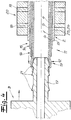
- connection unit 1 from a heated motor vehicle pipeline 2 for the passage of a fluid medium and a heatable connector 3 for connection to the motor vehicle pipeline 2.
- the connector may be preferred and in the embodiment designed as a quick connector (Quick Connector). It is recommended that an aqueous urea solution for a catalyst system of a motor vehicle be passed as a fluid medium through the pipe 2 and through the connector 3.
- the pipeline has an inner layer 4, which is in contact with the fluid medium conducted through the pipeline 2 (not shown in the figures) on its inner surface.
- the pipe 2 in the embodiment of the Fig. 1 to 8 an inner first heat conductor layer 5 adjoining the inner layer and a second outer heat conductor layer 6.
- the two heating conductor layers 5, 6 are preferably the forward and return lines for the heating current and, to that extent, both layers are preferably connected in series.
- Both Schuleiter füren 5, 6 expediently and in the embodiment over the circumference of the pipe 2 to. This may be heat conductor layers 5, 6 made of conductive plastic.
- the two heating conductor layers 5, 6 are separated from each other by an electrically insulating separating layer 7.
- This outer layer 8 serves in particular for the external protection of the heating conductor layers 5, 6 against, for example, mechanical stresses.
- an outer protective layer 10 is still arranged, which protects the pipeline 2 from external mechanical influences and corrosive influences.
- the thermal insulation layer 9 and the outer protection layer 10 were placed in the FIGS. 2 to 8 not shown.
- the two heating conductor layers 5, 6 of the pipeline 2 extend over the length of the pipeline 2. They extend into the connecting section 11 of the pipeline 2.
- the first inner heating conductor layer 5 has a first outwardly open or uncovered heating segment 12 which provides a first electrical contact region 13 of the connecting section 11 or the pipeline 2.
- the second heating conductor layer 6 has a second, uncovered, uncovered heating segment 14, which provides a second electrical contact region 15 for the second heating conductor layer 6.
- the ends of the two heat conductor layers 5, 6 or the two heating segments 12 and 14 in the connecting portion 11 is step-like or stepped. This also applies to the interposed insulating separating layer 7, which protrudes with a corresponding step portion 16 in the connecting portion 11 of the pipe 2.
- the two electrical contact areas 13, 15 of the pipeline 2 come directly into electrically conductive contact with electrical contact points or with two electrical contact points 18 and 19 of the pipe 2 and connector 3 or when pushing together / plugging the pipe 2 and connector Connector 3 or a connecting sleeve 20.
- the electrical contact between the contact areas 13 and 15 of the pipe 2 and the connecting portion 11 and the two contact points 18, 19 of the connector 3 and the connecting sleeve 20 is carried out alone Pushing together or plugging together the components.
- a solder joint or crimp connection or the like between the contact areas 13, 15 and the electrical contact points 18, 19 is basically not necessary.
- FIGS. 2 to 8 It can be seen that according to a preferred embodiment and in the embodiment when establishing the connection between connector 3 and pipe 2, a mandrel 17 of the connector 3 in the interior of the pipe 2 can be inserted or inserted.
- the mandrel 17 on its outer side profiles - preferably and in the embodiment sawtooth-shaped profilings 21 - on.
- the first contact region 13 and the second contact region 15 are pressed or bent outward in particular under the action of the sawtooth-shaped profilings 21, so that the electrical contact between the contact regions 13, 15 and the electrical contact points 18, 19 of Connector 3 and the connecting sleeve 20 allows or facilitates.
- FIG. 5 Incidentally, it has been indicated by arrows on the connecting section 11 that the connecting section 11 and the mandrel 17 can be welded together, preferably by means of laser welding.
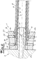
- the connector 3 has a cylindrical annular groove 22, in which annular groove 22 of the connecting portion 11 of the pipe 2 is inserted in establishing the connection between the connector 3 and pipe 2.
- annular groove 22 of the connecting portion 11 of the pipe 2 is inserted in establishing the connection between the connector 3 and pipe 2.
- the electrical contact points 18, 19 of the connector are arranged on the pipe side or connecting portion side inner surface of the annular groove 22 .
- the electrical contact pads 18, 19 of the connector 3 are connected to connector heating conductors, which may be formed as Verbinderschreibleiter Anlagenen 23, 24.
- Such connector heating conductor layers 23, 24, which preferably circulate over the entire circumference of the connector 3, are in the FIGS. 7 and 8th been hinted at.
- a stepped arrangement of the two heating segments 12, 14 or of the two contact regions 13, 15 of the connecting section 11 is realized.
- the inner surface of the annular groove 22 is conically formed in its front region, so that an effective electrical contact between the contact regions 13, 15 and the contact points 18, 19 can take place.
- This inner surface of the annular groove 22 could also - according to the formation of the connecting portion 11 - be designed step-shaped. In principle, the inner surface of the annular groove could also be formed only cylindrical.
- the connecting portion 11 with its contact areas 13, 15 between the mandrel 17 and the inner surface of the annular groove 22 as it were clamped, so that due to the clamping action a reliable electrical contact between the contact areas 13, 15 and the contact points 18, 19 results.
- FIGS. 4 to 8 show a connection of a connector 3 with a motor vehicle pipeline 2, including a connecting sleeve 20.
- a cylindrical connecting sleeve 20 is pushed onto the connecting section 11 of the pipeline 2 here.
- the connecting sleeve 20 surrounds the pipeline 2 and has a corresponding receiving channel 25 for the pipeline 2.
- the two electrical contact points 18, 19 are arranged, which when pushing or plugging the connection sleeve 20 are brought into electrical contact contact with the electrical contact areas 13, 15 of the connection section 11 or the pipeline 2.
- the mandrel 17 of the connector 3 is expediently inserted into the interior of the pipeline 2 or of the connecting section 11 (see in particular FIG. 5 ).
- the sawtooth-like profilings 21 of the mandrel 17 With the sawtooth-like profilings 21 of the mandrel 17, a pushing out or bending out of the electrical contact regions 13, 15 to the outside or in the direction of the contact points 18, 19 of the connecting sleeve 20 is achieved.
- the connecting portion 11 is clamped with its contact areas 13, 15 between the mandrel 17 and the connecting sleeve 20 as it were.
- the electrical contact points 18, 19 of the connecting sleeve 20 are connected to external electrical connections 27 of the connecting sleeve 20.
- the external electrical connections 27 are arranged on the outside of the connecting sleeve 20 facing away from the connecting section 11.
- the electrical contact points 18, 19 of the connection sleeve 20 are connected to the connector heating conductor layers 23, 24 extending through the connector 3 and heating the connector.
- the connector heater layers 23, 24 preferably extend at least over most of the length of the connector 3 and are recommended to run around the circumference of the connector Connector 3 um.
- the connector heating conductor layers 23, 24 may, like the heating conductor layers 5, 6 of the pipeline, consist of a conductive plastic. You could also consist of a metal foil or the like electrically conductive material.
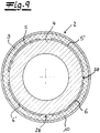
- the Fig. 9 shows another embodiment of a pipe according to the invention 2.
- four Bankleiter Anlagenen 5, 5 ', 6, 6' applied to the pipe 2 and an inner layer 4 of the pipe.
- This Bankleiter füren 5, 5 ', 6, 6' were printed by means of a printing process on the pipe 2 and on the inner layer 4.
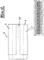
- the Fig. 10 shows, the Schuleiter füren 5, 5 ', 6, 6' extend over the length of the pipe 2.
- the four Schuleiter füren 5, 5 ', 6, 6' are arranged as it were on a circumferential plane of the pipe 2 over the circumference of the pipe 2 side by side ( Fig. 9 ).
- An outer layer 8 is basically not required in this embodiment for the pipe 2.
- the Fig. 9 shows a thermal insulating layer 9 disposed on the heating conductor layers 5, 5 ', 6, 6'. Over the thermal insulating layer 9, an outer protective layer 10 is applied.
- Fig. 9 and 10 show that between the extending over the length of the pipe 2 Edelleiter Anlagenen 5, 5 ', 6, 6' gaps 28 are provided which separate these Bankleiter füren 5, 5 ', 6, 6' from each other or isolating from each other.
- a heat conductor layer 5, 5 ', 6, 6' over the length of the pipe 2 need not be formed continuously.
- FIGS. 11 and 12 show a connection sleeve 20 for the connection of a pipeline 2 according to the Fig. 9 and 10 to a connector 3 (connected state in FIG Fig. 13 ).
- the connecting sleeve has four sleeve heating conductor layers 29 for electrical contact with the heating conductor layers 5, 5 ', 6, 6' of the pipeline 2.
- the sleeve heating conductor layers 29 can in principle also be printed onto the connecting sleeve 20 by means of a printing method.
- the connector 3 has connector heating conductor layers 23, 24 printed on the connector 3 by a printing method. These connector heating conductor layers 23, 24 are brought into contact with the sleeve heating conductor layers 29 of the connecting sleeve 20 ( Fig. 13 ).
- the electrical contact between the contact areas 13, 15 of the pipe 2 and the contact points 18, 19 of the connector 3 and the connecting sleeve 20 only by pushing together or plugging together of the pipe 2 and connector 3 when establishing the connection between the pipe 2 and connector 3 or realized by connecting sleeve 20.
- the electrical connection between contact areas 13, 15 and contact points 18, 19 is preferably formed solder-free and / or crimp connection-free and / or screw connection and / or adhesive-free. Special and complex connection measures of the electrical contacts are basically not required within the scope of the invention.
Landscapes
- Engineering & Computer Science (AREA)
- General Engineering & Computer Science (AREA)
- Mechanical Engineering (AREA)
- Chemical & Material Sciences (AREA)
- Combustion & Propulsion (AREA)
- Resistance Heating (AREA)
- Pipe Accessories (AREA)
Claims (19)
- Ensemble de raccordement (1) composé d'une conduite chauffable de véhicule automobile (2) pour faire passer un milieu fluide et d'un raccord (3) pour le raccordement avec la conduite de véhicule automobile (2), la conduite (2) comportant au moins un conducteur chauffant mince, au moins un conducteur chauffant s'étendant sur la longueur de la conduite (2) ou s'étendant pour l'essentiel sur la longueur de la conduite (2) et s'étendant jusque dans une section de raccordement (11) de la conduite (2) pour le raccordement avec le raccord (3),
au moins un conducteur chauffant mince sur la section de raccordement (11) de la conduite (2) comportant une zone de contact électrique (13, 15) et lors du raccordement de la conduite (2) au raccord (3) ou lors du télescopage et/ou de l'emboîtement de la conduite (2) et du raccord (3), la zone de contact électrique (13, 15) de la conduite (2) vient en contact électroconducteur avec un point de contact électrique (18, 19) du raccord (3) ou un manchon de raccordement (20) appliqué au ou sur la section de raccordement (11) au cours du raccordement de la conduite (2) et du raccord (3),
lors de l'établissement de la liaison entre le raccord (3) et la conduite (2), une broche (17) du raccord (3) peut être insérée ou emboîtée à l'intérieur de la conduite (2),
lors de l'insertion ou de l'emboîtement de la broche (17), la zone de contact (13, 15) étant comprimée ou courbée vers l'extérieur de sorte que le contact électrique de la zone de contact est possible ou facilité avec les points de contact électriques du raccord ou du manchon de raccordement,
et la broche (17) comportant sur son côté extérieur des profilages en forme de dents de scie (21), les profilages en forme de dents de scie (21) facilitant ou simplifiant la compression ou le glissement de la première et/ou de la deuxième zone de contact (13, 15) vers l'extérieur, - Ensemble de raccordement selon la revendication 1, la conduite (2) comportant une couche intérieure (4), qui est en contact avec le milieu fluide guidé à travers la conduite (2), la conduite (2) comportant de préférence au moins une couche extérieure (8) et au moins un conducteur chauffant mince étant disposé entre la couche intérieure (4) et la couche extérieure (8).
- Ensemble de raccordement selon l'une quelconque des revendications 1 ou 2, au moins un conducteur chauffant mince étant constitué comme couche de conducteur chauffant (5, 6) de la conduite (2), la couche de conducteur chauffant (5, 6) entourant au moins une partie de la périphérie de la conduite (2) et passant autour sur toute la périphérie de la conduite (2) selon une forme d'exécution.
- Ensemble de raccordement selon l'une quelconque des revendications 1 à 3, la conduite (2) comportant au moins un premier conducteur chauffant mince et au moins un deuxième conducteur chauffant mince, les deux conducteurs chauffants s'étendant sur la longueur de la conduite (2) ou s'étendant pour l'essentiel sur la longueur de la conduite (2) et s'étendant jusque dans une section de raccordement (11) de la conduite (2) pour le raccordement avec le raccord (3), les deux conducteurs chauffants sur la section de raccordement (11) de la conduite (2) comportant respectivement une zone de contact électrique (13, 15) et lors du raccordement de la conduite (2) avec le raccord (3) ou lors du télescopage et/ou de l'emboîtement de la conduite (2) et du raccord (3), les deux zones de contact électriques (13, 15) de la conduite (2) venant en contact électroconducteur avec au moins deux points de contact électriques (18, 19) du raccord (3) ou un manchon de raccordement (20) appliqué à ou sur la section de raccordement (11) au cours du raccordement de la conduite (2) et du raccord (3).
- Ensemble de raccordement selon la revendication 4, une couche de séparation (7) ou une couche de séparation électriquement isolante (7) étant intercalée entre le premier conducteur chauffant mince ou entre la première couche de conducteur chauffant (5) et le deuxième conducteur chauffant mince ou la deuxième couche de conducteur chauffant (6).
- Ensemble de raccordement selon l'une quelconque des revendications 3 à 5, au moins une première et/ou au moins une deuxième couche de conducteur chauffant (5, 6) étant constituée d'un matériau métallique ou pour l'essentiel d'un matériau métallique et de préférence constituée sous forme de feuille métallique ou sous forme de film métallique.
- Ensemble de raccordement selon l'une quelconque des revendications 3 à 6, au moins une première couche de conducteur chauffant (5) et/ou au moins une deuxième couche de conducteur chauffant (6) étant composée au moins d'un polymère conducteur ou d'une matière plastique conductrice.
- Ensemble de raccordement selon l'une quelconque des revendications 1 à 7, au moins un premier segment chauffant (12) formant ou comportant la première zone de contact électrique (13) d'au moins un premier conducteur chauffant mince ou d'au moins une première couche de conducteur chauffant (5) est disposé dans la section de raccordement (11) de la conduite (2) sur la surface extérieure de la conduite (2) ou de la section de raccordement (11).
- Ensemble de raccordement selon l'une quelconque des revendications 1 à 8, au moins un deuxième segment chauffant (14) formant ou comportant la deuxième zone de contact électrique (15) d'au moins un deuxième conducteur chauffant mince ou d'au moins une deuxième couche de conducteur chauffant (6) est disposé dans la section de raccordement (11) de la conduite (2) sur la surface extérieure de la conduite (2) ou de la section de raccordement (11).
- Ensemble de raccordement selon l'une quelconque des revendications 1 à 9, le premier segment chauffant (12) du premier conducteur chauffant mince ou de la première couche de conducteur chauffant (5) et le deuxième segment chauffant (14) du deuxième conducteur chauffant mince ou de la deuxième couche de conducteur chauffant (6) étant disposés dans la section de raccordement (11) de la conduite (2).
- Ensemble de raccordement selon l'une quelconque des revendications 1 à 10, lors de l'insertion ou de l'emboîtement de la broche (17), la première zone de contact (13) ou le premier segment chauffant (12) et la deuxième zone de contact (15) ou le deuxième segment chauffant (14) étant comprimé ou poussé vers l'extérieur de manière à permettre ou faciliter le contact électrique avec les points de contact électriques (18, 19) du raccord (3) ou du manchon de raccordement (20).
- Ensemble de raccordement selon l'une quelconque des revendications 1 à 11, le raccord (3) comportant une rainure annulaire (22), rainure annulaire (22) dans laquelle la conduite (2) ou la section de raccordement (11) de la conduite (2) pouvant être insérée lors de l'établissement du raccordement entre le raccord (3) et la conduite (2) et au moins un point de contact électrique (18, 19) du raccord (3) ou les points de contact électriques (18, 19) du raccord (3) étant disposés sur la surface intérieure côté conduite ou côté section de raccordement de la rainure annulaire (22).
- Ensemble de raccordement selon l'une quelconque des revendications 1 à 12, un manchon de raccordement (20) pouvant être inséré ou emboîté sur la section de raccordement (11) de la conduite (2) pour établir un contact électrique, au moins un point de contact électrique (18, 19) ou les points de contact électriques (18, 19) étant disposés sur le côté intérieur du côté de la section de raccordement (26) du manchon de raccordement (20), qui vient/viennent en contact électrique lors de l'insertion ou de l'emboîtement avec au moins une zone de contact électrique (13, 15) ou avec les zones de contacts électriques (13, 15) de la section de raccordement (11).
- Ensemble de raccordement selon l'une quelconque des revendications 1 à 13, au moins un point de contact électrique (18, 19) ou les points de contact électriques (18, 19) du raccord (3) et/ou du manchon de raccordement (20) étant reliés avec au moins un conducteur chauffant de raccord passant le long du raccord (3) et chauffant le raccord (3), le ou les conducteur(s) chauffant(s) de raccord s'étendant de préférence sur au moins la majeure partie de la longueur du raccord (3).
- Ensemble de raccordement selon l'une quelconque des revendications 1 à 14, au moins un conducteur chauffant de raccord disposé dans le raccord (3) et pour chauffer le raccord (3) étant configuré sous la forme d'une couche de conducteur chauffant de raccord (23, 24), qui passe de préférence autour de la majeure partie de la périphérie du raccord et de façon recommandée sur toute la périphérie du raccord.
- Ensemble de raccordement selon l'une quelconque des revendications 1 à 15, lors de l'établissement du raccordement entre la conduite (2) et le raccord (3), le contact électrique entre la zone de contact (13, 15) ou les zones de contact (13, 15) de la conduite (2) et du point de contact (18, 19) ou des points de contact (18, 19) du raccord (3) ou du manchon de raccordement (20) est réalisé grâce au télescopage ou à l'emboîtement de la conduite (2) et du raccord (3) et le cas échéant du manchon de raccordement (20).
- Ensemble de raccordement selon l'une quelconque des revendications 1 à 16, au moins un conducteur chauffant mince ou les conducteurs chauffants minces, en particulier au moins une couche de conducteur chauffant (5, 6) ou les couches de conducteur chauffant (5, 6) est/sont appliqué(s) sur la conduite par pression au moyen d'un procédé de pression.
- Ensemble de raccordement selon l'une quelconque des revendications 14 à 17, au moins un conducteur chauffant de raccord ou les conducteurs chauffants de raccord, en particulier au moins une couche de conducteur chauffant de raccord (23, 24) ou les couches de conducteur chauffant de raccord (23, 24) est/sont appliqué(s) sur le raccord par pression au moyen d'un procédé de pression.
- Ensemble de raccordement selon l'une quelconque des revendications 1 à 18, le manchon de raccordement (20) étant configuré sous la forme d'une pince ou d'une attache.
Priority Applications (1)
| Application Number | Priority Date | Filing Date | Title |
|---|---|---|---|
| EP13194096.7A EP2876273B1 (fr) | 2013-11-22 | 2013-11-22 | Module de liaison constitué d'une conduite de véhicule automobile pouvant être chauffée et d'un connecteur pouvant être chauffé |
Applications Claiming Priority (1)
| Application Number | Priority Date | Filing Date | Title |
|---|---|---|---|
| EP13194096.7A EP2876273B1 (fr) | 2013-11-22 | 2013-11-22 | Module de liaison constitué d'une conduite de véhicule automobile pouvant être chauffée et d'un connecteur pouvant être chauffé |
Publications (2)
| Publication Number | Publication Date |
|---|---|
| EP2876273A1 EP2876273A1 (fr) | 2015-05-27 |
| EP2876273B1 true EP2876273B1 (fr) | 2017-01-04 |
Family
ID=49709468
Family Applications (1)
| Application Number | Title | Priority Date | Filing Date |
|---|---|---|---|
| EP13194096.7A Not-in-force EP2876273B1 (fr) | 2013-11-22 | 2013-11-22 | Module de liaison constitué d'une conduite de véhicule automobile pouvant être chauffée et d'un connecteur pouvant être chauffé |
Country Status (1)
| Country | Link |
|---|---|
| EP (1) | EP2876273B1 (fr) |
Family Cites Families (4)
| Publication number | Priority date | Publication date | Assignee | Title |
|---|---|---|---|---|
| US5544275A (en) * | 1993-03-17 | 1996-08-06 | Applied Materials, Inc. | Electrically heated fluid carrying conduit having integrated heating elements and electrical conductors |
| DE102005048943A1 (de) * | 2005-10-13 | 2007-04-19 | Phoenix Fluid Handling Industry Gmbh | Beheizbarer Schlauch |
| DE202009012230U1 (de) * | 2009-06-23 | 2010-11-04 | Voss Automotive Gmbh | Elektrisch beheizbare Medienleitung sowie Leitungsverbinder |
| FR2958991B1 (fr) * | 2010-04-14 | 2012-05-04 | Total Sa | Conduite pour le transport d'un fluide comprenant un hydrocarbure, et procede de fabrication d'une telle conduite. |
-
2013
- 2013-11-22 EP EP13194096.7A patent/EP2876273B1/fr not_active Not-in-force
Also Published As
| Publication number | Publication date |
|---|---|
| EP2876273A1 (fr) | 2015-05-27 |
Similar Documents
| Publication | Publication Date | Title |
|---|---|---|
| EP2641006B1 (fr) | Conduite de fluides confectionnée à chauffage électrique et procédé de fabrication de ladite conduite | |
| EP1519098B1 (fr) | Conduit de transport de fluide à chauffage électrique | |
| EP3372736B1 (fr) | Appareil de liaison | |
| DE202010006739U1 (de) | Durchlauferhitzer | |
| EP3158250B1 (fr) | Conduite de fluide | |
| EP3276243B1 (fr) | Conduite de fluide de vehicule automobile | |
| WO2011110408A2 (fr) | Protection de conduites d'eau contre le gel | |
| DE102013000588A1 (de) | Konfektionierte beheizbare Medienleitung, Verwendung einer solchen sowie Verfahren zum Herstellen einer solchen | |
| EP2418364B1 (fr) | Conduite pouvant être chauffée | |
| EP1387440B1 (fr) | Méthode pour mettre à la masse une conduite métallique revêtue et un clip à utiliser pour cette méthode | |
| EP2496874B1 (fr) | Système de raccordement de conduites flexibles | |
| EP2801743B1 (fr) | Procédé permettant de relier un connecteur de conduite avec une conduite de véhicule automobile contenant un fluide | |
| EP2876273B1 (fr) | Module de liaison constitué d'une conduite de véhicule automobile pouvant être chauffée et d'un connecteur pouvant être chauffé | |
| EP3477178B1 (fr) | Tuyau flexible chauffable à élément chauffant monté | |
| DE202014003776U1 (de) | Kunststoffrohr | |
| EP1764541A1 (fr) | Dispositif de chauffage électrique, tuyau chauffable et son procédé de fabrication | |
| EP3234434B1 (fr) | Conduite de fluide chauffante et procédé pour fabriquer une conduite de fluide chauffante | |
| EP2979018A1 (fr) | Conduite de fluide équipée d'un dispositif chauffe-raccord | |
| DE202007007125U1 (de) | Heizmittel zur Erwärmung eines Fluids | |
| DE202015009640U1 (de) | Schweißverbinder | |
| EP2401892A1 (fr) | Dispositif de chauffage électrique | |
| DE102020106220B3 (de) | Heizschlauch-Wellrohr-Verbindung | |
| DE102018208252A1 (de) | Verfahren zur Herstellung einer Heizeinrichtung und damit hergestellte Heizeinrichtung | |
| EP1463153B1 (fr) | Procédé de mise à la terre d'une conduite métallique revêtue et une conduite métallique revêtue | |
| EP3831586A1 (fr) | Procédé de fabrication d'un tuyau chauffable et dispositif de fixation associé |
Legal Events
| Date | Code | Title | Description |
|---|---|---|---|
| PUAI | Public reference made under article 153(3) epc to a published international application that has entered the european phase |
Free format text: ORIGINAL CODE: 0009012 |
|
| 17P | Request for examination filed |
Effective date: 20141124 |
|
| AK | Designated contracting states |
Kind code of ref document: A1 Designated state(s): AL AT BE BG CH CY CZ DE DK EE ES FI FR GB GR HR HU IE IS IT LI LT LU LV MC MK MT NL NO PL PT RO RS SE SI SK SM TR |
|
| AX | Request for extension of the european patent |
Extension state: BA ME |
|
| RBV | Designated contracting states (corrected) |
Designated state(s): AL AT BE BG CH CY CZ DE DK EE ES FI FR GB GR HR HU IE IS IT LI LT LU LV MC MK MT NL NO PL PT RO RS SE SI SK SM TR |
|
| 17Q | First examination report despatched |
Effective date: 20151124 |
|
| GRAP | Despatch of communication of intention to grant a patent |
Free format text: ORIGINAL CODE: EPIDOSNIGR1 |
|
| INTG | Intention to grant announced |
Effective date: 20160614 |
|
| GRAS | Grant fee paid |
Free format text: ORIGINAL CODE: EPIDOSNIGR3 |
|
| GRAA | (expected) grant |
Free format text: ORIGINAL CODE: 0009210 |
|
| AK | Designated contracting states |
Kind code of ref document: B1 Designated state(s): AL AT BE BG CH CY CZ DE DK EE ES FI FR GB GR HR HU IE IS IT LI LT LU LV MC MK MT NL NO PL PT RO RS SE SI SK SM TR |
|
| REG | Reference to a national code |
Ref country code: GB Ref legal event code: FG4D Free format text: NOT ENGLISH |
|
| REG | Reference to a national code |
Ref country code: CH Ref legal event code: EP |
|
| REG | Reference to a national code |
Ref country code: AT Ref legal event code: REF Ref document number: 859458 Country of ref document: AT Kind code of ref document: T Effective date: 20170115 |
|
| REG | Reference to a national code |
Ref country code: IE Ref legal event code: FG4D Free format text: LANGUAGE OF EP DOCUMENT: GERMAN |
|
| REG | Reference to a national code |
Ref country code: DE Ref legal event code: R096 Ref document number: 502013005964 Country of ref document: DE |
|
| REG | Reference to a national code |
Ref country code: LT Ref legal event code: MG4D Ref country code: NL Ref legal event code: MP Effective date: 20170104 |
|
| PG25 | Lapsed in a contracting state [announced via postgrant information from national office to epo] |
Ref country code: NL Free format text: LAPSE BECAUSE OF FAILURE TO SUBMIT A TRANSLATION OF THE DESCRIPTION OR TO PAY THE FEE WITHIN THE PRESCRIBED TIME-LIMIT Effective date: 20170104 |
|
| PG25 | Lapsed in a contracting state [announced via postgrant information from national office to epo] |
Ref country code: IS Free format text: LAPSE BECAUSE OF FAILURE TO SUBMIT A TRANSLATION OF THE DESCRIPTION OR TO PAY THE FEE WITHIN THE PRESCRIBED TIME-LIMIT Effective date: 20170504 Ref country code: FI Free format text: LAPSE BECAUSE OF FAILURE TO SUBMIT A TRANSLATION OF THE DESCRIPTION OR TO PAY THE FEE WITHIN THE PRESCRIBED TIME-LIMIT Effective date: 20170104 Ref country code: NO Free format text: LAPSE BECAUSE OF FAILURE TO SUBMIT A TRANSLATION OF THE DESCRIPTION OR TO PAY THE FEE WITHIN THE PRESCRIBED TIME-LIMIT Effective date: 20170404 Ref country code: HR Free format text: LAPSE BECAUSE OF FAILURE TO SUBMIT A TRANSLATION OF THE DESCRIPTION OR TO PAY THE FEE WITHIN THE PRESCRIBED TIME-LIMIT Effective date: 20170104 Ref country code: GR Free format text: LAPSE BECAUSE OF FAILURE TO SUBMIT A TRANSLATION OF THE DESCRIPTION OR TO PAY THE FEE WITHIN THE PRESCRIBED TIME-LIMIT Effective date: 20170405 Ref country code: LT Free format text: LAPSE BECAUSE OF FAILURE TO SUBMIT A TRANSLATION OF THE DESCRIPTION OR TO PAY THE FEE WITHIN THE PRESCRIBED TIME-LIMIT Effective date: 20170104 |
|
| PG25 | Lapsed in a contracting state [announced via postgrant information from national office to epo] |
Ref country code: PT Free format text: LAPSE BECAUSE OF FAILURE TO SUBMIT A TRANSLATION OF THE DESCRIPTION OR TO PAY THE FEE WITHIN THE PRESCRIBED TIME-LIMIT Effective date: 20170504 Ref country code: BG Free format text: LAPSE BECAUSE OF FAILURE TO SUBMIT A TRANSLATION OF THE DESCRIPTION OR TO PAY THE FEE WITHIN THE PRESCRIBED TIME-LIMIT Effective date: 20170404 Ref country code: SE Free format text: LAPSE BECAUSE OF FAILURE TO SUBMIT A TRANSLATION OF THE DESCRIPTION OR TO PAY THE FEE WITHIN THE PRESCRIBED TIME-LIMIT Effective date: 20170104 Ref country code: PL Free format text: LAPSE BECAUSE OF FAILURE TO SUBMIT A TRANSLATION OF THE DESCRIPTION OR TO PAY THE FEE WITHIN THE PRESCRIBED TIME-LIMIT Effective date: 20170104 Ref country code: ES Free format text: LAPSE BECAUSE OF FAILURE TO SUBMIT A TRANSLATION OF THE DESCRIPTION OR TO PAY THE FEE WITHIN THE PRESCRIBED TIME-LIMIT Effective date: 20170104 Ref country code: RS Free format text: LAPSE BECAUSE OF FAILURE TO SUBMIT A TRANSLATION OF THE DESCRIPTION OR TO PAY THE FEE WITHIN THE PRESCRIBED TIME-LIMIT Effective date: 20170104 Ref country code: LV Free format text: LAPSE BECAUSE OF FAILURE TO SUBMIT A TRANSLATION OF THE DESCRIPTION OR TO PAY THE FEE WITHIN THE PRESCRIBED TIME-LIMIT Effective date: 20170104 |
|
| REG | Reference to a national code |
Ref country code: DE Ref legal event code: R097 Ref document number: 502013005964 Country of ref document: DE |
|
| PG25 | Lapsed in a contracting state [announced via postgrant information from national office to epo] |
Ref country code: RO Free format text: LAPSE BECAUSE OF FAILURE TO SUBMIT A TRANSLATION OF THE DESCRIPTION OR TO PAY THE FEE WITHIN THE PRESCRIBED TIME-LIMIT Effective date: 20170104 Ref country code: SK Free format text: LAPSE BECAUSE OF FAILURE TO SUBMIT A TRANSLATION OF THE DESCRIPTION OR TO PAY THE FEE WITHIN THE PRESCRIBED TIME-LIMIT Effective date: 20170104 Ref country code: IT Free format text: LAPSE BECAUSE OF FAILURE TO SUBMIT A TRANSLATION OF THE DESCRIPTION OR TO PAY THE FEE WITHIN THE PRESCRIBED TIME-LIMIT Effective date: 20170104 Ref country code: EE Free format text: LAPSE BECAUSE OF FAILURE TO SUBMIT A TRANSLATION OF THE DESCRIPTION OR TO PAY THE FEE WITHIN THE PRESCRIBED TIME-LIMIT Effective date: 20170104 Ref country code: CZ Free format text: LAPSE BECAUSE OF FAILURE TO SUBMIT A TRANSLATION OF THE DESCRIPTION OR TO PAY THE FEE WITHIN THE PRESCRIBED TIME-LIMIT Effective date: 20170104 |
|
| PLBE | No opposition filed within time limit |
Free format text: ORIGINAL CODE: 0009261 |
|
| STAA | Information on the status of an ep patent application or granted ep patent |
Free format text: STATUS: NO OPPOSITION FILED WITHIN TIME LIMIT |
|
| REG | Reference to a national code |
Ref country code: FR Ref legal event code: PLFP Year of fee payment: 5 |
|
| PG25 | Lapsed in a contracting state [announced via postgrant information from national office to epo] |
Ref country code: DK Free format text: LAPSE BECAUSE OF FAILURE TO SUBMIT A TRANSLATION OF THE DESCRIPTION OR TO PAY THE FEE WITHIN THE PRESCRIBED TIME-LIMIT Effective date: 20170104 Ref country code: SM Free format text: LAPSE BECAUSE OF FAILURE TO SUBMIT A TRANSLATION OF THE DESCRIPTION OR TO PAY THE FEE WITHIN THE PRESCRIBED TIME-LIMIT Effective date: 20170104 |
|
| 26N | No opposition filed |
Effective date: 20171005 |
|
| PG25 | Lapsed in a contracting state [announced via postgrant information from national office to epo] |
Ref country code: SI Free format text: LAPSE BECAUSE OF FAILURE TO SUBMIT A TRANSLATION OF THE DESCRIPTION OR TO PAY THE FEE WITHIN THE PRESCRIBED TIME-LIMIT Effective date: 20170104 |
|
| PG25 | Lapsed in a contracting state [announced via postgrant information from national office to epo] |
Ref country code: MC Free format text: LAPSE BECAUSE OF FAILURE TO SUBMIT A TRANSLATION OF THE DESCRIPTION OR TO PAY THE FEE WITHIN THE PRESCRIBED TIME-LIMIT Effective date: 20170104 |
|
| GBPC | Gb: european patent ceased through non-payment of renewal fee |
Effective date: 20171122 |
|
| PG25 | Lapsed in a contracting state [announced via postgrant information from national office to epo] |
Ref country code: CH Free format text: LAPSE BECAUSE OF NON-PAYMENT OF DUE FEES Effective date: 20171130 Ref country code: LI Free format text: LAPSE BECAUSE OF NON-PAYMENT OF DUE FEES Effective date: 20171130 |
|
| PG25 | Lapsed in a contracting state [announced via postgrant information from national office to epo] |
Ref country code: LU Free format text: LAPSE BECAUSE OF NON-PAYMENT OF DUE FEES Effective date: 20171122 |
|
| REG | Reference to a national code |
Ref country code: BE Ref legal event code: MM Effective date: 20171130 |
|
| REG | Reference to a national code |
Ref country code: IE Ref legal event code: MM4A |
|
| PG25 | Lapsed in a contracting state [announced via postgrant information from national office to epo] |
Ref country code: MT Free format text: LAPSE BECAUSE OF FAILURE TO SUBMIT A TRANSLATION OF THE DESCRIPTION OR TO PAY THE FEE WITHIN THE PRESCRIBED TIME-LIMIT Effective date: 20170104 |
|
| PG25 | Lapsed in a contracting state [announced via postgrant information from national office to epo] |
Ref country code: IE Free format text: LAPSE BECAUSE OF NON-PAYMENT OF DUE FEES Effective date: 20171122 |
|
| PG25 | Lapsed in a contracting state [announced via postgrant information from national office to epo] |
Ref country code: GB Free format text: LAPSE BECAUSE OF NON-PAYMENT OF DUE FEES Effective date: 20171122 Ref country code: BE Free format text: LAPSE BECAUSE OF NON-PAYMENT OF DUE FEES Effective date: 20171130 |
|
| PG25 | Lapsed in a contracting state [announced via postgrant information from national office to epo] |
Ref country code: HU Free format text: LAPSE BECAUSE OF FAILURE TO SUBMIT A TRANSLATION OF THE DESCRIPTION OR TO PAY THE FEE WITHIN THE PRESCRIBED TIME-LIMIT; INVALID AB INITIO Effective date: 20131122 |
|
| PG25 | Lapsed in a contracting state [announced via postgrant information from national office to epo] |
Ref country code: CY Free format text: LAPSE BECAUSE OF FAILURE TO SUBMIT A TRANSLATION OF THE DESCRIPTION OR TO PAY THE FEE WITHIN THE PRESCRIBED TIME-LIMIT Effective date: 20170104 |
|
| PG25 | Lapsed in a contracting state [announced via postgrant information from national office to epo] |
Ref country code: MK Free format text: LAPSE BECAUSE OF FAILURE TO SUBMIT A TRANSLATION OF THE DESCRIPTION OR TO PAY THE FEE WITHIN THE PRESCRIBED TIME-LIMIT Effective date: 20170104 |
|
| REG | Reference to a national code |
Ref country code: AT Ref legal event code: MM01 Ref document number: 859458 Country of ref document: AT Kind code of ref document: T Effective date: 20181122 |
|
| PG25 | Lapsed in a contracting state [announced via postgrant information from national office to epo] |
Ref country code: AT Free format text: LAPSE BECAUSE OF NON-PAYMENT OF DUE FEES Effective date: 20181122 |
|
| PGFP | Annual fee paid to national office [announced via postgrant information from national office to epo] |
Ref country code: DE Payment date: 20191128 Year of fee payment: 7 |
|
| PGFP | Annual fee paid to national office [announced via postgrant information from national office to epo] |
Ref country code: FR Payment date: 20191128 Year of fee payment: 7 |
|
| PG25 | Lapsed in a contracting state [announced via postgrant information from national office to epo] |
Ref country code: TR Free format text: LAPSE BECAUSE OF FAILURE TO SUBMIT A TRANSLATION OF THE DESCRIPTION OR TO PAY THE FEE WITHIN THE PRESCRIBED TIME-LIMIT Effective date: 20170104 |
|
| PG25 | Lapsed in a contracting state [announced via postgrant information from national office to epo] |
Ref country code: AL Free format text: LAPSE BECAUSE OF FAILURE TO SUBMIT A TRANSLATION OF THE DESCRIPTION OR TO PAY THE FEE WITHIN THE PRESCRIBED TIME-LIMIT Effective date: 20170104 |
|
| REG | Reference to a national code |
Ref country code: DE Ref legal event code: R119 Ref document number: 502013005964 Country of ref document: DE |
|
| PG25 | Lapsed in a contracting state [announced via postgrant information from national office to epo] |
Ref country code: FR Free format text: LAPSE BECAUSE OF NON-PAYMENT OF DUE FEES Effective date: 20201130 |
|
| PG25 | Lapsed in a contracting state [announced via postgrant information from national office to epo] |
Ref country code: DE Free format text: LAPSE BECAUSE OF NON-PAYMENT OF DUE FEES Effective date: 20210601 |
|
| P01 | Opt-out of the competence of the unified patent court (upc) registered |
Effective date: 20230524 |