EP2876339A2 - Système de construction pour un robinet à soupape et robinet à soupape pour un chauffage basse température - Google Patents
Système de construction pour un robinet à soupape et robinet à soupape pour un chauffage basse température Download PDFInfo
- Publication number
- EP2876339A2 EP2876339A2 EP14190954.9A EP14190954A EP2876339A2 EP 2876339 A2 EP2876339 A2 EP 2876339A2 EP 14190954 A EP14190954 A EP 14190954A EP 2876339 A2 EP2876339 A2 EP 2876339A2
- Authority
- EP
- European Patent Office
- Prior art keywords
- valve
- fitting
- valve fitting
- cover
- installation
- Prior art date
- Legal status (The legal status is an assumption and is not a legal conclusion. Google has not performed a legal analysis and makes no representation as to the accuracy of the status listed.)
- Granted
Links
Images


Classifications
-
- F—MECHANICAL ENGINEERING; LIGHTING; HEATING; WEAPONS; BLASTING
- F16—ENGINEERING ELEMENTS AND UNITS; GENERAL MEASURES FOR PRODUCING AND MAINTAINING EFFECTIVE FUNCTIONING OF MACHINES OR INSTALLATIONS; THERMAL INSULATION IN GENERAL
- F16K—VALVES; TAPS; COCKS; ACTUATING-FLOATS; DEVICES FOR VENTING OR AERATING
- F16K27/00—Construction of housing; Use of materials therefor
- F16K27/12—Covers for housings
-
- F—MECHANICAL ENGINEERING; LIGHTING; HEATING; WEAPONS; BLASTING
- F24—HEATING; RANGES; VENTILATING
- F24D—DOMESTIC- OR SPACE-HEATING SYSTEMS, e.g. CENTRAL HEATING SYSTEMS; DOMESTIC HOT-WATER SUPPLY SYSTEMS; ELEMENTS OR COMPONENTS THEREFOR
- F24D19/00—Details
- F24D19/0097—Casings or frame structures for hydraulic components
-
- F—MECHANICAL ENGINEERING; LIGHTING; HEATING; WEAPONS; BLASTING
- F24—HEATING; RANGES; VENTILATING
- F24D—DOMESTIC- OR SPACE-HEATING SYSTEMS, e.g. CENTRAL HEATING SYSTEMS; DOMESTIC HOT-WATER SUPPLY SYSTEMS; ELEMENTS OR COMPONENTS THEREFOR
- F24D19/00—Details
- F24D19/10—Arrangement or mounting of control or safety devices
- F24D19/1006—Arrangement or mounting of control or safety devices for water heating systems
- F24D19/1009—Arrangement or mounting of control or safety devices for water heating systems for central heating
- F24D19/1015—Arrangement or mounting of control or safety devices for water heating systems for central heating using a valve or valves
-
- G—PHYSICS
- G05—CONTROLLING; REGULATING
- G05D—SYSTEMS FOR CONTROLLING OR REGULATING NON-ELECTRIC VARIABLES
- G05D23/00—Control of temperature
- G05D23/01—Control of temperature without auxiliary power
- G05D23/02—Control of temperature without auxiliary power with sensing element expanding and contracting in response to changes of temperature
- G05D23/021—Control of temperature without auxiliary power with sensing element expanding and contracting in response to changes of temperature the sensing element being a non-metallic solid, e.g. elastomer, paste
- G05D23/023—Control of temperature without auxiliary power with sensing element expanding and contracting in response to changes of temperature the sensing element being a non-metallic solid, e.g. elastomer, paste the sensing element being placed outside a regulating fluid flow
-
- F—MECHANICAL ENGINEERING; LIGHTING; HEATING; WEAPONS; BLASTING
- F24—HEATING; RANGES; VENTILATING
- F24D—DOMESTIC- OR SPACE-HEATING SYSTEMS, e.g. CENTRAL HEATING SYSTEMS; DOMESTIC HOT-WATER SUPPLY SYSTEMS; ELEMENTS OR COMPONENTS THEREFOR
- F24D2220/00—Components of central heating installations excluding heat sources
- F24D2220/02—Fluid distribution means
- F24D2220/025—Check valves
-
- F—MECHANICAL ENGINEERING; LIGHTING; HEATING; WEAPONS; BLASTING
- F24—HEATING; RANGES; VENTILATING
- F24D—DOMESTIC- OR SPACE-HEATING SYSTEMS, e.g. CENTRAL HEATING SYSTEMS; DOMESTIC HOT-WATER SUPPLY SYSTEMS; ELEMENTS OR COMPONENTS THEREFOR
- F24D2220/00—Components of central heating installations excluding heat sources
- F24D2220/02—Fluid distribution means
- F24D2220/0257—Thermostatic valves
-
- F—MECHANICAL ENGINEERING; LIGHTING; HEATING; WEAPONS; BLASTING
- F24—HEATING; RANGES; VENTILATING
- F24D—DOMESTIC- OR SPACE-HEATING SYSTEMS, e.g. CENTRAL HEATING SYSTEMS; DOMESTIC HOT-WATER SUPPLY SYSTEMS; ELEMENTS OR COMPONENTS THEREFOR
- F24D3/00—Hot-water central heating systems
- F24D3/12—Tube and panel arrangements for ceiling, wall, or underfloor heating
- F24D3/122—Details
- F24D3/125—Hydraulic pipe connections
-
- Y—GENERAL TAGGING OF NEW TECHNOLOGICAL DEVELOPMENTS; GENERAL TAGGING OF CROSS-SECTIONAL TECHNOLOGIES SPANNING OVER SEVERAL SECTIONS OF THE IPC; TECHNICAL SUBJECTS COVERED BY FORMER USPC CROSS-REFERENCE ART COLLECTIONS [XRACs] AND DIGESTS
- Y02—TECHNOLOGIES OR APPLICATIONS FOR MITIGATION OR ADAPTATION AGAINST CLIMATE CHANGE
- Y02B—CLIMATE CHANGE MITIGATION TECHNOLOGIES RELATED TO BUILDINGS, e.g. HOUSING, HOUSE APPLIANCES OR RELATED END-USER APPLICATIONS
- Y02B30/00—Energy efficient heating, ventilation or air conditioning [HVAC]
Definitions
- the invention relates to an installation arrangement for the installation of a valve fitting comprising a thermostatic valve whose controller protrudes through an opening of a closure cover, in particular for a low temperature heating with a return temperature or sudlauftemperaturbegrenzer, often referred to simply as RTL valve, for limiting the return temperature of the low temperature heating and a thermostatic valve disposed downstream in series with the return temperature valve.
- valve fitting On site, such a valve fitting is often installed in a housing which can be closed by a removable cover.
- the thermostatic valve of the valve fitting is adjustable by means of a control element rotatably mounted in the cover, preferably designed as a rotary control.
- the housing for receiving the valves connected to the lines of the heater valve fitting is often referred to simply as RTL or Einbaubox.
- Such a valve fitting is for example from the DE 10 2005 043 255 B3 known.
- heated heating water flows from a boiler in an inlet for the heating medium of the valve fitting with a flow temperature of about 70 ° Celsius in the system and is distributed to a radiator and a in one Ground recessed heating loop, for example, in a bath, wherein the heating water cools with the release of heat to the radiator and the floor. Finally, the cooled heating water flows through the valve fitting, within which the RTL valve is arranged.
- the control element in the RTL valve is thus flowed around by the Schufitwasser exiting from the Schuweflife and cooled heating water and thus regulates first emerging from the system return temperature by preventing the temperature within the adoptedêtitzschleife is too high, which can lead to damage in the soil.
- the RTL valve thus detects the return temperature of the water flowing out of the underfloor heating loop and regulates its flow rate through the system.
- An in the flow direction behind the RTL valve, so downstream arranged thermostatic valve detects the room air and regulates the flow in addition to this room air.
- This thermostatic valve is usually directly accessible and adjustable without disassembly, whereas the RTL valve is usually embedded in a box-like box, a so-called Einbaubox or RTL box in a recess in the wall near the floor and only after disassembly of a cover of the Einbaubox is accessible.
- RTL or built-in boxes for mounting the valve fitting in installation position are usually mounted directly in the wall in the shell and can be closed by a removable cover.
- the controller of the thermostatic valve is rotatably received in the cover for accessibility from the outside, so that its projection depends on the particular installation situation in the finished installation with the used up height of the plaster, the wall covering, etc., whereby the controller more or less far out, what sometimes elaborate reworking required.
- the thermostatic heads used are about 65 mm and longer.
- today's controllers look out of the wall between approx. 50 mm and 70 mm.
- today's covers of RTL installation boxes are approx. 155 x 200 mm in size.
- the valve body is permanently installed in the installation box.
- the present invention seeks to at least partially avoid these disadvantages and in particular to provide a valve fitting and a Einbaubox that is easier to install and significantly smaller than existing Einbauboxen.
- the adjusting means according to the invention thus allow an individual and accurate adjustment of the relative position of the valve fitting in the housing in relation to the cover, taking into account the individual circumstances in the context of fine installation.
- these adjustment means comprise a length-adjustable intermediate member for connecting the thermostat with the thermostatic valve.
- the actuating element of the thermostatic valve, in particular the rotary knob, with the expansion body disposed therein was always at a fixed distance to the valve body of the thermostatic valve and thus provoked a more or less protruding actuator, can now by the length-adjustable pontic, which is arranged between the actuator and the valve body, the overall system of the installation box can be adjusted to the specific installation situation.
- the inventive construction it is thus possible to bring the cover plate and the thermostat so in the context of fine installation that their location is only dependent on the location of the wall surface.
- the intermediate member or connecting element according to the invention is provided, which can either be formed in different lengths or is adjustable to the respective fine construction situation, to bridge or adjust the distance between the plunger and piston of the rotary knob and the thermostatic valve body as needed.
- the adjustable variant can e.g. a variable length pin with end caps for insertion between the working piston of the dial and the thermostatic valve body, which is connected by a fixing system, e.g. a locking system to the exact nominal length is adjustable.
- the intermediate member is preferably designed as variable-length plunger and can be formed in a particularly simple embodiment, for example, as a shortenable plastic rod, preferably comprising different pliers marks, or as a threaded rod which is received in a threaded bush and whose length is adjustable by rotation.
- the adjusting element of the thermostatic valve comprises a Dehnscherlement with a working piston which closes a spring-loaded valve seat with temperature increase, thereby controlling the Schumacherstrom until the preset temperature at the sensor element or sensor element is again fallen below. Subsequently, the valve can open again by the spring load by the volume reduction in the expansion element. It adjusts a control loop.
- the adjusting means are adapted to adapt the position of the valve body with respect to its relative position to the cover in the housing or the Einbaubox. Even so, the distance between the thermostatic valve head to the surface of the wall can be adjusted as needed in the context of fine installation.
- a movable valve body preferably by means of an adjustable connecting element, arranged between the valve fitting and cover.
- the preferred embodiment provides for the formation of the connecting element as adjusting screws, particularly preferably supplemented by a spacer sleeve. These adjusting screws are screwed in the mounting position on the front side in the cover and thus accessible. These adjustment screws act with their distal, rear end to adjust the valve fitting.
- valve fitting preferably releasably attached to the retaining element, for example by means of fastening clips.
- the distance between the thermostatic valve head and cover can still be individually adjusted and adjusted during the fine installation.
- these position fixing means comprise on the inside of the housing provided guide pins, which are preferably integrally formed on the inside and engage in the fitting and / or the retaining element in a position-fixing.
- connection of the valve fitting to the pipes or pipes preferably takes place via movable pipes.
- an elongated Rohbaubox be used, which has a deeper, in the installed position top valve receiving portion and a subsequent subordinate pipe section lesser depth.
- this pipe section can first be concealed and plastered with a cover on the front. The further assembly and arrangement of the valve fitting is then realized only by means of the valve receiving portion of the Einbaubox, which is accessible to the cover or a cover plate.
- Another aspect of the invention includes the manner of the connection technique of the valve fitting with the flow line and the return line.
- the prior art has hitherto included screw or clamp connections for connecting the valve fitting with the projecting from the wall or the floor Cables.
- the loosening of the connection technology is always complicated in the confined space of the Einbaubox in corners and in the floor area because of the limited accessibility.
- To simplify the valve assembly at the initial assembly and disassembly for maintenance is also proposed to equip the ends of the lines with insertable into the lines and the valve fitting fittings that are sealingly releasably connectable to the valve body.
- the fittings comprise double-sided spigot and a preferably centrally between the spigot radially transversely to the longitudinal direction of the fitting projecting and circumferential abutment flange.
- the spigot on one side of the fitting are preferably permanently connected to a line and the opposite plug-in connection releasably connected to the valve fitting.
- the releasable attachment of the fitting with the valve fitting is preferably via a clip or a split pin, which is inserted into the valve fitting so that it surrounds the insertion of the fitting in the installed position or clamps.
- the insertion stubs are designed to realize an offset in the adjustment of the valve fitting. This is particularly preferably done by a material recess, for example a groove, which allows movement in a certain range of about 3 to 5 mm.
- This groove is preferably provided on the Einsteckstutzen, in which the engaging in the installation position fastening means is movable. This avoids that the connecting lines in the Depth setting under tension.
- a preferred embodiment of the installation box also comprises means for preventing excessive heating of the space within the closed by the cover Einbaubox in operation.
- the heating fluid flowing through the valve fitting often leads to a disproportionate warming of the interior within the closed Einbaubox, causing an undesirable effect on the heat-sensitive expansion element within the thermostatic valve, which is actually the Jardinlauft in the is to capture heating space, so that it closes early and undesirably.
- a special ventilation technique is proposed, which prevents excessive heating within the Einbaubox.
- this ventilation technology ventilation holes at the top and bottom of the cover which allows a flow through the Einbaubox with ambient air due to the chimney effect.
- air circulation ducts laid laterally inside the installation box and in the wall are provided, which open into the room at an unrecognized location, for example in the area of the skirting boards or behind cabinets.
- the space between the thermostatic valve head and the installation box can be insulated. Due to the slower heat transfer between the installation box and the thermostatic valve, heat changes within the installation box are not significant compared to the heat changes in the room.
- valve fitting itself.
- the smallest possible design of the installation box is desirable so that it does not have to be placed in the foot or at the bottom of the room in hidden positions, where this is always difficult is accessible.
- Desirable would be the arrangement in the field of easy access similar to a normal light switch, only with a knob to set the desired temperature.
- combined RTL and thermostatic valves in a valve fitting are always relatively large, so that they significantly determine the size of the Einbaubox to its inclusion in the wall.
- the RTL valve does not have to sit on the outside of the valve fitting as usual, so must be located outside of the actual valve body, but rather can be integrated into this valve body, preferably in the inflow side of a valve fitting. This results in a possibility of reducing the size of the valve fitting by up to 60 percent compared to the prior art.
- the inflow and outflow of the valve body of the valve body extending substantially parallel to each other and are connected via a connecting portion, wherein the connecting portion preferably receives the thermostatic valve, particularly preferably the thermostatic valve is offset by 90 degrees to the longitudinal direction of the valve body, so also to the longitudinal direction of the RTL valve to ensure easy operability of the knob for the thermostatic valve in installation position.
- the RTL valve is received in the downstream side of the valve fitting and the thermostatic valve is disposed in a connecting portion between the upstream and downstream sides.
- the fitting housing is formed as a cast body produced in one piece.
- a further aspect of the invention adjusts to Valve fitting connectable vent valve, by means of which a venting of the heating circuit can be made.
- the housing of the mounting box can be designed as a substantially rectangular box with an edge length of about 100 x 80 mm.
- the built-in box comprises a substantially cube-shaped valve chamber of greater depth for receiving the valve fitting, for example, with a depth of 100mm, and an adjoining this valve space longer connection space lesser depth of eg 60 mm.
- a depth ratio of 1.5 to 1.6 at the depth of Ventilzu terminal space has resulted.
- the invention thus also relates to an installation method for the installation of a valve fitting in a previously described installation arrangement.
- This method comprises at least the following with the steps of: attaching a built-in box to a wall as part of a shell installation, connecting pipes to the valve fitting and prefixing the valve fitting in a valve space of the installation box in a prefixing position, finishing a wall surface surrounding the installation box, releasing the valve fitting from the Vorfix istsposition, providing adjustment means between cover and valve fitting, fixing the cover to the Einbaubox, fine alignment of the position of a mounting position protruding through the cover actuator of the valve fitting in relation to the cover attached to the Einbaubox by means of the adjustment.
- the method steps may or may not necessarily be performed in this order.
- the installation box can be preferably shortened before fixing the cover and is preferably designed for this purpose, for example by means of Predetermined breaking points.
- the wall surface may have one or more layers of plaster, drywall, wallpaper, paint, tile, wood, natural stone or other wallcoverings.
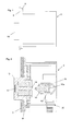
- FIGS. 1 to 5 the first embodiment of the invention, in which the adjusting means comprise an adjustable or variable connecting element between the rotary knob and the thermostatic valve.
- valve fitting 4 is embedded in a box-shaped Einbaubox 2 in a surrounding wall 6 in a corresponding recess.
- the front opening of the Einbaubox is closed by a plate-shaped and removable cover 8.
- a circular cylindrical knob 10 is rotatably received. Trained as an aluminum body knob 10 takes on its inside in a cylindrical recess on an expansion body 12, or an expansion element whose inwardly projecting and variable-length working piston 14 presses in installation position against the front of a thermostatic valve body 16, which in turn guided longitudinally displaceable in the valve body 4 is with and depending on the setting of the knob 10 more or less spring-loaded with a rear-side thermostatic valve 16a against a thermostatic valve seat 4a of the valve fitting 4 and
- the flow of the heating medium as a function of the ambient temperature more or less limited, so regulates.
- valve fitting 4 comprises an integrally formed brass body in the essential shape of an H, with two longitudinally extending parallel to each other, designed as valve seats 4b and 4c longitudinal cylinder 4d over a transversely extending to this longitudinal direction connecting portion are integrally connected to each other with a passage opening.
- the valve seats 4b and 4c each have at the lower end a first circular-cylindrical attachment portion with a first smaller outer and inner diameter, which then merges into a middle section adjoining this, forming a first outer and inner shoulder, which has a larger inner diameter. and outer diameter than the attachment portion and then finally merges each forming a second outer and inner shoulder into a top portion, the inner and outer diameter are in turn each larger than the diameter of the central portion.
- the three sections thus define the valve seats 4b, 4c of the valve fitting 4 for accommodating valves, in particular an RTL valve, of which only one RTL valve 18 is arranged in the feed side of the valve fitting 4 in the figures.
- the right-side valve seat 4b in the figures is closed by a sealing plug (not shown) screwed in at the top.
- sealing plug 38 may be provided instead of the sealing plug 38 for the purpose of venting a vent valve.
- the valve fitting 4 is sealingly placed with its lower attachment stub to fittings 20, 22, which are formed here as a press fitting via not shown press connections with plastic lines 24, 26 are connected to guide the heating medium.
- the RTL valve 18 accordingly comprises an expansion element 28 which is flowed around by the heating water and which acts at its lower end with a valve cone 30 on a valve seat 32 formed in the valve section 4b at the lower end of the middle section on the shoulder for passage into the fastening section.
- the expansion element 28 is in a cup-like receiving sleeve 29 with devis furnishedem Used federal, against which a receiving sleeve 29 surrounding lower coil spring 34 rests on the upper side and the bottom rests against the shoulder between the central portion and mounting portion of the valve seat 4b.
- the expansion element 28 is inserted on the valve cone 30 opposite upper end in a stopper cap 31, on the outer flange of an upper coil spring 36 sits with its top against the inside of a screwed into the valve seat in the upper portion of the valve seat 4c knob 38 of the RTL Valve pushes.
- the closing temperature of the RTL valve 18 can be adjusted very precisely as needed by pressing the knob 38.
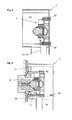
- FIGS. 6 and 7 show the second embodiment of the invention with differently shaped adjusting means, which act between the cover 46 and the valve body 4.
- the valve fitting 4 is otherwise constructed as in the first embodiment.
- the housing 40 of the installation box is inserted into a prefabricated recess in the wall 6.
- This extended Einbaubox has a mounting position in the upper box-like valve chamber 42 with a depth of about 100 mm for movably receiving the valve fitting 4 and a lower connection space 44 with a smaller depth of about 60 mm. These dimensions are merely exemplary and not mandatory.
- the valve chamber 42 is designed for the relatively movable receiving the valve fitting 4 and the connection space 44 serves to connect the lines 24, 26 to the valve fitting 4 and preferably also to reduce the voltage in the lines 24, 26, which could occur when moving the valve unit 4.
- the valve space 42 protruding from the wall of the housing 40 is cut flush with the wall. Then, the plate-shaped cover 46 is fixed to the front of the upper valve space 42 of the housing, e.g. by means screwed in the corners screws. Under the cover 46, an additional plate-shaped holding element or mounting frame 88 may be arranged, which may have a front-side depression for receiving the screw heads of the adjusting screws 48, 50.
- the entire valve fitting 4 by means of two long adjustment screws 48, 50 and the holder 52 for the valve fitting 4 with threaded holes for the adjusting screws 48, 50 to the adjusting screws 48, 50 enclosing spacers 54, 56 used until the Spacers 54, 56 defined distance to the cover 46 is realized exactly.
- spacers 54, 56 different length changes in the thickness of the wall covering can be compensated, which also allows a later needs-based adjustment.
- it is fastened to the holder 52 with two fastening clips 58, 60 which can be used detachably on the front side.
- the recorded on the inside of the expansion element in the knob 10 push rod 62 has a fixed length and thus presses evenly at each plaster thickness to 30 mm on the thermostatic valve body 16th
- the lower connecting pieces 64, 66 each have a longitudinal groove 74, 76, which in the longitudinal direction over about 5 mm on the outer surfaces of the upper mounting position and in the lower Connecting end of the valve fitting 4 inserted connecting pieces 64, 66 extends.
- the connecting pieces 64, 66 can move slightly vertically to absorb the change.
- the connecting pieces 64, 66 are also held releasably in the valve fitting 4 with clips 68, 70 in this embodiment.
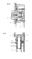
- valve 8 and 11 show the valve used in the mounting box 2 valve body 4 in the shell, so if the Einbaubox 2 is screwed either with its back with a wall, not shown, or inserted into a corresponding wall opening.
- the valve fitting 4 is screwed with two fixing screws 82, 84 on the back of the mounting box 2, so that the valve fitting 4 with the lines 24, 26 attached thereto is held so that these on a projecting into the interior of the Einbaubox support web 86th rests or sits on.
- the support web 86 also serves according to the enlarged view in FIG. 11 As a stop for the lines 24, 26 in the fittings 20, 22.
- the support web 86 thus ensures a certain protrusion or a game of fittings 22, 24 in the two insert pipe at the lower end of the valve body 4 for the realization of the vertical offset in the lower insert neck of the valve fitting 4 inserted fittings socket 64, 66 of the fittings 20, 22 in the vertical direction when transferring the valve fitting 4 from the shell to the fine construction position.
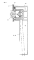
- FIG. 8 is the installation box in full length in which these also in accordance with the in FIG. 9 illustrated embodiment is used with thick wall construction, so if the wall thickness with plaster, tiles, wallpaper, etc. has a corresponding total thickness.
- the valve fitting 4 according to the invention is set at the correct distance from the front plane of the diaphragm 72 via the adjusting screws 48, 50 whose rear threaded end engage in the threaded holes for the fixing screws 82, 84.
- a cover 72 which is structurally adapted to the installation situation, can be detachably fastened to the cover 46, e.g. designed as an attachable glass panel.
- the invention provides an installation arrangement with adjusting means, which allow the on-site setting of the relative position of the actuating element in relation to a capping the installation assembly cover depending on the applied wall thickness in the fine construction position.
- this mounting arrangement comprises a front open, more preferably box-shaped Einbaubox which defines a valve chamber for receiving a valve fitting and can be closed by the cover.
- the acting between the cover and the valve body, and front operable adjustment means allow the alignment of the valve body with the actuator in relation to the reference line defining cover.
- the adjusting means comprise at least one adjusting screw inserted in the cover, which engages with a projecting into the valve chamber rear end in a corresponding thread in the valve fitting or a holder for the valve fitting for fine adjustment.
- the cover may further comprise a mounting frame, which has at least one opening for receiving the adjusting screw and possibly a depression, so that the front design cover is placed without spacing even when inserted adjusting screw.
- the pot-shaped knob 10 for receiving the expansion body is formed as a one-piece metal part, preferably made of aluminum, which does not have the required in the prior art made of plastic knobs cooling slots.
- the metal body of the knob is sufficiently large to dissipate the heat and heat and prevent distortions of the measurement result. This makes it possible to provide closed control buttons, which look like a light controller and therefore offer completely new design possibilities.
- the control knob is the expansion element, has from the expansion element in itself.
- the invention thus provides, for the first time by surprisingly simple means, an adaptation of the exact position of a valve fitting installed in a wall box in a wall box, the position of which can never be exactly determined due to the special installation situation.
- a variable-length connecting element preferably as a working piston or at least its extension is formed
- the exact position of the valve fitting in the Einbaubox, the special installation situation taking into account the material thickness of the applied wall covering and other conditions in the fine installation can be optimally taken into account for well-defined arrangement of the cover arranged in the knob, which for the first time highest designerischen requirements regarding the dimensional accuracy can be met.
- variable-length connecting element which comprises, for example, a threaded rod which can be screwed into a plug-on sleeve which can be plugged onto the thermostatic valve body and fixed to the required length.
- the invention provides a valve fitting which is particularly easy to install and dismantle, which merely has to be plugged onto the fittings provided at the ends of the lines 24, 26 and fixed in the installation position via cotter pins. This can even be done without tools. This allows a particularly simple installation and changing the valve inserts in case of maintenance essentially with standard components; so the entire valve fitting is simply completely removable.
- the invention also relates to a mounting kit comprising a Einbaubox, the valve fitting described at the beginning, fittings for connection to the lines of a floor heating, a valve fitting and the adjusting means according to the invention for adapting the valve fitting to the mounting position.
Landscapes
- Engineering & Computer Science (AREA)
- General Engineering & Computer Science (AREA)
- Physics & Mathematics (AREA)
- Mechanical Engineering (AREA)
- Thermal Sciences (AREA)
- Chemical & Material Sciences (AREA)
- Combustion & Propulsion (AREA)
- Fluid Mechanics (AREA)
- General Physics & Mathematics (AREA)
- Automation & Control Theory (AREA)
- Valve Housings (AREA)
- Control Of Temperature (AREA)
Applications Claiming Priority (1)
| Application Number | Priority Date | Filing Date | Title |
|---|---|---|---|
| DE102013221994 | 2013-10-29 |
Publications (3)
| Publication Number | Publication Date |
|---|---|
| EP2876339A2 true EP2876339A2 (fr) | 2015-05-27 |
| EP2876339A3 EP2876339A3 (fr) | 2015-08-19 |
| EP2876339B1 EP2876339B1 (fr) | 2018-06-13 |
Family
ID=51845307
Family Applications (1)
| Application Number | Title | Priority Date | Filing Date |
|---|---|---|---|
| EP14190954.9A Active EP2876339B1 (fr) | 2013-10-29 | 2014-10-29 | Système de construction pour un robinet à soupape et robinet à soupape pour un chauffage basse température |
Country Status (1)
| Country | Link |
|---|---|
| EP (1) | EP2876339B1 (fr) |
Cited By (3)
| Publication number | Priority date | Publication date | Assignee | Title |
|---|---|---|---|---|
| RU2736904C1 (ru) * | 2019-03-07 | 2020-11-23 | Овентроп Гмбх Унд Ко.Кг | Блок управления для систем отопления или охлаждения |
| CN113195943A (zh) * | 2019-03-07 | 2021-07-30 | 格鲁纳股份公司 | 调节阀减速传动机构 |
| CN115593156A (zh) * | 2022-10-20 | 2023-01-13 | 中策橡胶集团股份有限公司(Cn) | 一种缺气保用轮胎及其制造方法 |
Citations (1)
| Publication number | Priority date | Publication date | Assignee | Title |
|---|---|---|---|---|
| DE102005043255B3 (de) | 2005-09-09 | 2007-01-04 | Simplex Armaturen + Fittings Gmbh & Co. Kg | Ventilarmatur für Niedertemperaturheizungen mit einem Rücklauftemperaturbegrenzer |
Family Cites Families (18)
| Publication number | Priority date | Publication date | Assignee | Title |
|---|---|---|---|---|
| DE2910833C2 (de) * | 1979-03-20 | 1982-12-23 | Danfoss A/S, 6430 Nordborg | Ventilanordnung für eine Fußbodenheizung |
| DE3308070C2 (de) * | 1983-03-08 | 1985-01-17 | Wella Ag, 6100 Darmstadt | Temperaturabhängig steuerbares Heizungsventil mit Voreinstellvorrichtung |
| US4654900A (en) * | 1985-11-21 | 1987-04-07 | Mcghee Charles M | Bathtub valve fixture module |
| DE3625131A1 (de) * | 1986-07-25 | 1988-02-04 | Grohe Armaturen Friedrich | Unterputz-einbaukasten fuer mischbatterien o. dgl. |
| GB2312037B (en) * | 1996-04-09 | 2000-03-29 | Blue Circle Heating Ltd | Heat radiators |
| DE19955257C1 (de) * | 1999-11-17 | 2001-06-28 | Danfoss As | Ventil, insbesondere Thermostatventil für Heizungsanlagen |
| DE10119589C1 (de) * | 2001-04-21 | 2003-02-13 | Danfoss As | Ventil, insbesondere Thermostatventil für Heizungsanlagen |
| DE10130924A1 (de) * | 2001-06-27 | 2003-09-04 | Wolf Gmbh | Hydraulikverbindung für die Vor- und/oder Rücklaufleitung einer Gastherme |
| DE10148796A1 (de) * | 2001-10-02 | 2003-04-10 | Ralf Zumstrull | Ein Adapter als Verstelleinrichtung zur Voreinstellung eines Heizkörperventils |
| DE10312366B3 (de) * | 2003-03-20 | 2004-04-29 | Theodor Heimeier Metallwerk Gmbh & Co. Kg | Unterputzkasten für Raumheizungsregler |
| US20090145493A1 (en) * | 2004-11-23 | 2009-06-11 | Pip Co., Ltd. | Built-in wall water service box |
| DE102004058353B3 (de) * | 2004-12-03 | 2006-02-16 | Theodor Heimeier Metallwerk Gmbh & Co. Kg | Unterputzkasten mit Raumheizungsregler |
| GB2450700B (en) * | 2007-07-04 | 2009-12-23 | Philip Watson | Adjustable fluidic conduit |
| GB2458185A (en) * | 2008-03-12 | 2009-09-16 | John Ford | Radiator valve head replacement |
| DE102008052528A1 (de) * | 2008-10-21 | 2010-04-22 | Hansa Metallwerke Ag | Sanitäre Unterputzarmatur |
| DE202009016394U1 (de) * | 2009-12-02 | 2010-03-11 | Wachholz, Frank | Adapter als Rücklauftemperaturbegrenzer an Thermostatventilen |
| DE102011076210B4 (de) * | 2011-05-20 | 2017-03-16 | Hansgrohe Se | Befestigungsanordnung für zwei benachbarte Sanitärarmaturen |
| DE202011108342U1 (de) * | 2011-11-28 | 2012-02-15 | Oventrop Gmbh & Co. Kg | Montagekasten für verteilerlose Fußbodenheizung |
-
2014
- 2014-10-29 EP EP14190954.9A patent/EP2876339B1/fr active Active
Patent Citations (1)
| Publication number | Priority date | Publication date | Assignee | Title |
|---|---|---|---|---|
| DE102005043255B3 (de) | 2005-09-09 | 2007-01-04 | Simplex Armaturen + Fittings Gmbh & Co. Kg | Ventilarmatur für Niedertemperaturheizungen mit einem Rücklauftemperaturbegrenzer |
Cited By (4)
| Publication number | Priority date | Publication date | Assignee | Title |
|---|---|---|---|---|
| RU2736904C1 (ru) * | 2019-03-07 | 2020-11-23 | Овентроп Гмбх Унд Ко.Кг | Блок управления для систем отопления или охлаждения |
| CN113195943A (zh) * | 2019-03-07 | 2021-07-30 | 格鲁纳股份公司 | 调节阀减速传动机构 |
| US11933517B2 (en) | 2019-03-07 | 2024-03-19 | Gruner Ag | Butterfly flap reduction gear |
| CN115593156A (zh) * | 2022-10-20 | 2023-01-13 | 中策橡胶集团股份有限公司(Cn) | 一种缺气保用轮胎及其制造方法 |
Also Published As
| Publication number | Publication date |
|---|---|
| EP2876339A3 (fr) | 2015-08-19 |
| EP2876339B1 (fr) | 2018-06-13 |
Similar Documents
| Publication | Publication Date | Title |
|---|---|---|
| EP2876339B1 (fr) | Système de construction pour un robinet à soupape et robinet à soupape pour un chauffage basse température | |
| EP2876222A1 (fr) | Dispositif de fixation encastré pour un WC suspendu | |
| DE102008031558A1 (de) | Kopf- oder Seitenbrause | |
| DE29704807U1 (de) | Anschlußkasten | |
| DE102013201322A1 (de) | Sanitärarmatur mit tastenbetätigbarem Steuerorgan | |
| DE19912284B4 (de) | Kompaktheizungsanlage | |
| EP0918972B1 (fr) | Dispositif de support ou de montage pour element de chauffage | |
| EP2760090B1 (fr) | Système de fixation et kit d'intégration pour le montage d'une passerelle de montage dans une armoire de commande | |
| DE29511076U1 (de) | Heizkörperanordnung | |
| DE102011005365A1 (de) | Flächenheizeinrichtung und Anschlussbox | |
| EP3242978B1 (fr) | Raccord en s pour raccorder une conduite d'eau à un élément de robinetterie | |
| DE19909101C2 (de) | Steuergerät für einen Thermostatventilaufsatz | |
| EP2578759B1 (fr) | Mécanisme de verrouillage pour un égout | |
| EP0835412B1 (fr) | Dispositif de support, tel que console pour radiateurs plats a une ou plusieurs couches pourvus de toles de convection | |
| WO2015051936A1 (fr) | Dispositif permettant le raccordement de robinetteries sanitaires | |
| DE202004008946U1 (de) | Befestigungsvorrichtung | |
| DE102004058353B3 (de) | Unterputzkasten mit Raumheizungsregler | |
| DE20305054U1 (de) | Vorrichtung zum gemeinsamen Anschluß eines Heizkörpers und einer Fußbodenheizung an einen Heizungskreislauf | |
| DE29715784U1 (de) | Ventilgruppe für Fußbodenheizungen | |
| DE102019105750B4 (de) | Reglerbox für Heizungs- oder Kühlanlagen | |
| DE202009003122U1 (de) | Montageeinheit für Heizungs- und Sanitärinstallation | |
| DE202004017027U1 (de) | Installations-Bausatz zur Vorwand-Montage von sanitären Bauelementen sowie diesen Installations-Bausatz ... | |
| EP2902715B1 (fr) | Écran latéral pour un radiateur | |
| DE29907096U1 (de) | Ventileinrichtung mit radial ansetzender Betätigungseinrichtung | |
| DE9110740U1 (de) | Anschlußarmatur für einen Heizkörper |
Legal Events
| Date | Code | Title | Description |
|---|---|---|---|
| PUAI | Public reference made under article 153(3) epc to a published international application that has entered the european phase |
Free format text: ORIGINAL CODE: 0009012 |
|
| 17P | Request for examination filed |
Effective date: 20141029 |
|
| AK | Designated contracting states |
Kind code of ref document: A2 Designated state(s): AL AT BE BG CH CY CZ DE DK EE ES FI FR GB GR HR HU IE IS IT LI LT LU LV MC MK MT NL NO PL PT RO RS SE SI SK SM TR |
|
| AX | Request for extension of the european patent |
Extension state: BA ME |
|
| PUAL | Search report despatched |
Free format text: ORIGINAL CODE: 0009013 |
|
| AK | Designated contracting states |
Kind code of ref document: A3 Designated state(s): AL AT BE BG CH CY CZ DE DK EE ES FI FR GB GR HR HU IE IS IT LI LT LU LV MC MK MT NL NO PL PT RO RS SE SI SK SM TR |
|
| AX | Request for extension of the european patent |
Extension state: BA ME |
|
| RIC1 | Information provided on ipc code assigned before grant |
Ipc: F24D 19/10 20060101ALI20150713BHEP Ipc: F16K 27/12 20060101AFI20150713BHEP Ipc: F24D 19/00 20060101ALI20150713BHEP |
|
| R17P | Request for examination filed (corrected) |
Effective date: 20160219 |
|
| RBV | Designated contracting states (corrected) |
Designated state(s): AL AT BE BG CH CY CZ DE DK EE ES FI FR GB GR HR HU IE IS IT LI LT LU LV MC MK MT NL NO PL PT RO RS SE SI SK SM TR |
|
| 17Q | First examination report despatched |
Effective date: 20161125 |
|
| GRAP | Despatch of communication of intention to grant a patent |
Free format text: ORIGINAL CODE: EPIDOSNIGR1 |
|
| INTG | Intention to grant announced |
Effective date: 20170803 |
|
| GRAJ | Information related to disapproval of communication of intention to grant by the applicant or resumption of examination proceedings by the epo deleted |
Free format text: ORIGINAL CODE: EPIDOSDIGR1 |
|
| GRAP | Despatch of communication of intention to grant a patent |
Free format text: ORIGINAL CODE: EPIDOSNIGR1 |
|
| INTC | Intention to grant announced (deleted) | ||
| INTG | Intention to grant announced |
Effective date: 20180109 |
|
| INTG | Intention to grant announced |
Effective date: 20180118 |
|
| INTG | Intention to grant announced |
Effective date: 20180118 |
|
| GRAS | Grant fee paid |
Free format text: ORIGINAL CODE: EPIDOSNIGR3 |
|
| GRAA | (expected) grant |
Free format text: ORIGINAL CODE: 0009210 |
|
| AK | Designated contracting states |
Kind code of ref document: B1 Designated state(s): AL AT BE BG CH CY CZ DE DK EE ES FI FR GB GR HR HU IE IS IT LI LT LU LV MC MK MT NL NO PL PT RO RS SE SI SK SM TR |
|
| REG | Reference to a national code |
Ref country code: GB Ref legal event code: FG4D Free format text: NOT ENGLISH |
|
| REG | Reference to a national code |
Ref country code: CH Ref legal event code: EP Ref country code: AT Ref legal event code: REF Ref document number: 1008844 Country of ref document: AT Kind code of ref document: T Effective date: 20180615 |
|
| REG | Reference to a national code |
Ref country code: IE Ref legal event code: FG4D Free format text: LANGUAGE OF EP DOCUMENT: GERMAN |
|
| REG | Reference to a national code |
Ref country code: DE Ref legal event code: R096 Ref document number: 502014008524 Country of ref document: DE |
|
| REG | Reference to a national code |
Ref country code: NL Ref legal event code: MP Effective date: 20180613 |
|
| REG | Reference to a national code |
Ref country code: LT Ref legal event code: MG4D |
|
| PG25 | Lapsed in a contracting state [announced via postgrant information from national office to epo] |
Ref country code: ES Free format text: LAPSE BECAUSE OF FAILURE TO SUBMIT A TRANSLATION OF THE DESCRIPTION OR TO PAY THE FEE WITHIN THE PRESCRIBED TIME-LIMIT Effective date: 20180613 Ref country code: BG Free format text: LAPSE BECAUSE OF FAILURE TO SUBMIT A TRANSLATION OF THE DESCRIPTION OR TO PAY THE FEE WITHIN THE PRESCRIBED TIME-LIMIT Effective date: 20180913 Ref country code: CY Free format text: LAPSE BECAUSE OF FAILURE TO SUBMIT A TRANSLATION OF THE DESCRIPTION OR TO PAY THE FEE WITHIN THE PRESCRIBED TIME-LIMIT Effective date: 20180613 Ref country code: LT Free format text: LAPSE BECAUSE OF FAILURE TO SUBMIT A TRANSLATION OF THE DESCRIPTION OR TO PAY THE FEE WITHIN THE PRESCRIBED TIME-LIMIT Effective date: 20180613 Ref country code: FI Free format text: LAPSE BECAUSE OF FAILURE TO SUBMIT A TRANSLATION OF THE DESCRIPTION OR TO PAY THE FEE WITHIN THE PRESCRIBED TIME-LIMIT Effective date: 20180613 Ref country code: NO Free format text: LAPSE BECAUSE OF FAILURE TO SUBMIT A TRANSLATION OF THE DESCRIPTION OR TO PAY THE FEE WITHIN THE PRESCRIBED TIME-LIMIT Effective date: 20180913 Ref country code: SE Free format text: LAPSE BECAUSE OF FAILURE TO SUBMIT A TRANSLATION OF THE DESCRIPTION OR TO PAY THE FEE WITHIN THE PRESCRIBED TIME-LIMIT Effective date: 20180613 |
|
| PG25 | Lapsed in a contracting state [announced via postgrant information from national office to epo] |
Ref country code: HR Free format text: LAPSE BECAUSE OF FAILURE TO SUBMIT A TRANSLATION OF THE DESCRIPTION OR TO PAY THE FEE WITHIN THE PRESCRIBED TIME-LIMIT Effective date: 20180613 Ref country code: RS Free format text: LAPSE BECAUSE OF FAILURE TO SUBMIT A TRANSLATION OF THE DESCRIPTION OR TO PAY THE FEE WITHIN THE PRESCRIBED TIME-LIMIT Effective date: 20180613 Ref country code: GR Free format text: LAPSE BECAUSE OF FAILURE TO SUBMIT A TRANSLATION OF THE DESCRIPTION OR TO PAY THE FEE WITHIN THE PRESCRIBED TIME-LIMIT Effective date: 20180914 Ref country code: LV Free format text: LAPSE BECAUSE OF FAILURE TO SUBMIT A TRANSLATION OF THE DESCRIPTION OR TO PAY THE FEE WITHIN THE PRESCRIBED TIME-LIMIT Effective date: 20180613 |
|
| PG25 | Lapsed in a contracting state [announced via postgrant information from national office to epo] |
Ref country code: NL Free format text: LAPSE BECAUSE OF FAILURE TO SUBMIT A TRANSLATION OF THE DESCRIPTION OR TO PAY THE FEE WITHIN THE PRESCRIBED TIME-LIMIT Effective date: 20180613 |
|
| PG25 | Lapsed in a contracting state [announced via postgrant information from national office to epo] |
Ref country code: RO Free format text: LAPSE BECAUSE OF FAILURE TO SUBMIT A TRANSLATION OF THE DESCRIPTION OR TO PAY THE FEE WITHIN THE PRESCRIBED TIME-LIMIT Effective date: 20180613 Ref country code: SK Free format text: LAPSE BECAUSE OF FAILURE TO SUBMIT A TRANSLATION OF THE DESCRIPTION OR TO PAY THE FEE WITHIN THE PRESCRIBED TIME-LIMIT Effective date: 20180613 Ref country code: PL Free format text: LAPSE BECAUSE OF FAILURE TO SUBMIT A TRANSLATION OF THE DESCRIPTION OR TO PAY THE FEE WITHIN THE PRESCRIBED TIME-LIMIT Effective date: 20180613 Ref country code: CZ Free format text: LAPSE BECAUSE OF FAILURE TO SUBMIT A TRANSLATION OF THE DESCRIPTION OR TO PAY THE FEE WITHIN THE PRESCRIBED TIME-LIMIT Effective date: 20180613 Ref country code: IS Free format text: LAPSE BECAUSE OF FAILURE TO SUBMIT A TRANSLATION OF THE DESCRIPTION OR TO PAY THE FEE WITHIN THE PRESCRIBED TIME-LIMIT Effective date: 20181013 Ref country code: EE Free format text: LAPSE BECAUSE OF FAILURE TO SUBMIT A TRANSLATION OF THE DESCRIPTION OR TO PAY THE FEE WITHIN THE PRESCRIBED TIME-LIMIT Effective date: 20180613 |
|
| PG25 | Lapsed in a contracting state [announced via postgrant information from national office to epo] |
Ref country code: SM Free format text: LAPSE BECAUSE OF FAILURE TO SUBMIT A TRANSLATION OF THE DESCRIPTION OR TO PAY THE FEE WITHIN THE PRESCRIBED TIME-LIMIT Effective date: 20180613 Ref country code: IT Free format text: LAPSE BECAUSE OF FAILURE TO SUBMIT A TRANSLATION OF THE DESCRIPTION OR TO PAY THE FEE WITHIN THE PRESCRIBED TIME-LIMIT Effective date: 20180613 |
|
| REG | Reference to a national code |
Ref country code: DE Ref legal event code: R097 Ref document number: 502014008524 Country of ref document: DE |
|
| PLBE | No opposition filed within time limit |
Free format text: ORIGINAL CODE: 0009261 |
|
| STAA | Information on the status of an ep patent application or granted ep patent |
Free format text: STATUS: NO OPPOSITION FILED WITHIN TIME LIMIT |
|
| 26N | No opposition filed |
Effective date: 20190314 |
|
| PG25 | Lapsed in a contracting state [announced via postgrant information from national office to epo] |
Ref country code: DK Free format text: LAPSE BECAUSE OF FAILURE TO SUBMIT A TRANSLATION OF THE DESCRIPTION OR TO PAY THE FEE WITHIN THE PRESCRIBED TIME-LIMIT Effective date: 20180613 Ref country code: SI Free format text: LAPSE BECAUSE OF FAILURE TO SUBMIT A TRANSLATION OF THE DESCRIPTION OR TO PAY THE FEE WITHIN THE PRESCRIBED TIME-LIMIT Effective date: 20180613 |
|
| REG | Reference to a national code |
Ref country code: CH Ref legal event code: PL |
|
| GBPC | Gb: european patent ceased through non-payment of renewal fee |
Effective date: 20181029 |
|
| REG | Reference to a national code |
Ref country code: BE Ref legal event code: MM Effective date: 20181031 |
|
| PG25 | Lapsed in a contracting state [announced via postgrant information from national office to epo] |
Ref country code: LU Free format text: LAPSE BECAUSE OF NON-PAYMENT OF DUE FEES Effective date: 20181029 Ref country code: MC Free format text: LAPSE BECAUSE OF FAILURE TO SUBMIT A TRANSLATION OF THE DESCRIPTION OR TO PAY THE FEE WITHIN THE PRESCRIBED TIME-LIMIT Effective date: 20180613 |
|
| REG | Reference to a national code |
Ref country code: IE Ref legal event code: MM4A |
|
| PG25 | Lapsed in a contracting state [announced via postgrant information from national office to epo] |
Ref country code: LI Free format text: LAPSE BECAUSE OF NON-PAYMENT OF DUE FEES Effective date: 20181031 Ref country code: BE Free format text: LAPSE BECAUSE OF NON-PAYMENT OF DUE FEES Effective date: 20181031 Ref country code: FR Free format text: LAPSE BECAUSE OF NON-PAYMENT OF DUE FEES Effective date: 20181031 Ref country code: CH Free format text: LAPSE BECAUSE OF NON-PAYMENT OF DUE FEES Effective date: 20181031 |
|
| PG25 | Lapsed in a contracting state [announced via postgrant information from national office to epo] |
Ref country code: GB Free format text: LAPSE BECAUSE OF NON-PAYMENT OF DUE FEES Effective date: 20181029 Ref country code: IE Free format text: LAPSE BECAUSE OF NON-PAYMENT OF DUE FEES Effective date: 20181029 |
|
| PG25 | Lapsed in a contracting state [announced via postgrant information from national office to epo] |
Ref country code: AL Free format text: LAPSE BECAUSE OF FAILURE TO SUBMIT A TRANSLATION OF THE DESCRIPTION OR TO PAY THE FEE WITHIN THE PRESCRIBED TIME-LIMIT Effective date: 20180613 |
|
| PG25 | Lapsed in a contracting state [announced via postgrant information from national office to epo] |
Ref country code: MT Free format text: LAPSE BECAUSE OF FAILURE TO SUBMIT A TRANSLATION OF THE DESCRIPTION OR TO PAY THE FEE WITHIN THE PRESCRIBED TIME-LIMIT Effective date: 20180613 |
|
| PG25 | Lapsed in a contracting state [announced via postgrant information from national office to epo] |
Ref country code: TR Free format text: LAPSE BECAUSE OF FAILURE TO SUBMIT A TRANSLATION OF THE DESCRIPTION OR TO PAY THE FEE WITHIN THE PRESCRIBED TIME-LIMIT Effective date: 20180613 |
|
| PG25 | Lapsed in a contracting state [announced via postgrant information from national office to epo] |
Ref country code: PT Free format text: LAPSE BECAUSE OF FAILURE TO SUBMIT A TRANSLATION OF THE DESCRIPTION OR TO PAY THE FEE WITHIN THE PRESCRIBED TIME-LIMIT Effective date: 20180613 |
|
| PG25 | Lapsed in a contracting state [announced via postgrant information from national office to epo] |
Ref country code: MK Free format text: LAPSE BECAUSE OF NON-PAYMENT OF DUE FEES Effective date: 20180613 Ref country code: HU Free format text: LAPSE BECAUSE OF FAILURE TO SUBMIT A TRANSLATION OF THE DESCRIPTION OR TO PAY THE FEE WITHIN THE PRESCRIBED TIME-LIMIT; INVALID AB INITIO Effective date: 20141029 |
|
| P01 | Opt-out of the competence of the unified patent court (upc) registered |
Effective date: 20230527 |
|
| PGFP | Annual fee paid to national office [announced via postgrant information from national office to epo] |
Ref country code: AT Payment date: 20231019 Year of fee payment: 10 |
|
| REG | Reference to a national code |
Ref country code: AT Ref legal event code: MM01 Ref document number: 1008844 Country of ref document: AT Kind code of ref document: T Effective date: 20241029 |
|
| PG25 | Lapsed in a contracting state [announced via postgrant information from national office to epo] |
Ref country code: AT Free format text: LAPSE BECAUSE OF NON-PAYMENT OF DUE FEES Effective date: 20241029 |
|
| PGFP | Annual fee paid to national office [announced via postgrant information from national office to epo] |
Ref country code: DE Payment date: 20251024 Year of fee payment: 12 |
|
| REG | Reference to a national code |
Ref country code: DE Ref legal event code: R081 Ref document number: 502014008524 Country of ref document: DE Owner name: TECE SE, DE Free format text: FORMER OWNER: TECE GMBH, 48282 EMSDETTEN, DE |