EP2876352B1 - Nutzfahrzeug mit Druckgasbehälter - Google Patents
Nutzfahrzeug mit Druckgasbehälter Download PDFInfo
- Publication number
- EP2876352B1 EP2876352B1 EP14002812.7A EP14002812A EP2876352B1 EP 2876352 B1 EP2876352 B1 EP 2876352B1 EP 14002812 A EP14002812 A EP 14002812A EP 2876352 B1 EP2876352 B1 EP 2876352B1
- Authority
- EP
- European Patent Office
- Prior art keywords
- pressurized gas
- utility vehicle
- gas container
- container
- vehicle
- Prior art date
- Legal status (The legal status is an assumption and is not a legal conclusion. Google has not performed a legal analysis and makes no representation as to the accuracy of the status listed.)
- Active
Links
Images

Classifications
-
- F—MECHANICAL ENGINEERING; LIGHTING; HEATING; WEAPONS; BLASTING
- F17—STORING OR DISTRIBUTING GASES OR LIQUIDS
- F17C—VESSELS FOR CONTAINING OR STORING COMPRESSED, LIQUEFIED OR SOLIDIFIED GASES; FIXED-CAPACITY GAS-HOLDERS; FILLING VESSELS WITH, OR DISCHARGING FROM VESSELS, COMPRESSED, LIQUEFIED, OR SOLIDIFIED GASES
- F17C1/00—Pressure vessels, e.g. gas cylinder, gas tank, replaceable cartridge
- F17C1/16—Pressure vessels, e.g. gas cylinder, gas tank, replaceable cartridge constructed of plastics materials
-
- B—PERFORMING OPERATIONS; TRANSPORTING
- B60—VEHICLES IN GENERAL
- B60T—VEHICLE BRAKE CONTROL SYSTEMS OR PARTS THEREOF; BRAKE CONTROL SYSTEMS OR PARTS THEREOF, IN GENERAL; ARRANGEMENT OF BRAKING ELEMENTS ON VEHICLES IN GENERAL; PORTABLE DEVICES FOR PREVENTING UNWANTED MOVEMENT OF VEHICLES; VEHICLE MODIFICATIONS TO FACILITATE COOLING OF BRAKES
- B60T13/00—Transmitting braking action from initiating means to ultimate brake actuator with power assistance or drive; Brake systems incorporating such transmitting means, e.g. air-pressure brake systems
- B60T13/10—Transmitting braking action from initiating means to ultimate brake actuator with power assistance or drive; Brake systems incorporating such transmitting means, e.g. air-pressure brake systems with fluid assistance, drive, or release
- B60T13/24—Transmitting braking action from initiating means to ultimate brake actuator with power assistance or drive; Brake systems incorporating such transmitting means, e.g. air-pressure brake systems with fluid assistance, drive, or release the fluid being gaseous
- B60T13/26—Compressed-air systems
- B60T13/268—Compressed-air systems using accumulators or reservoirs
-
- B—PERFORMING OPERATIONS; TRANSPORTING
- B60—VEHICLES IN GENERAL
- B60R—VEHICLES, VEHICLE FITTINGS, OR VEHICLE PARTS, NOT OTHERWISE PROVIDED FOR
- B60R11/00—Arrangements for holding or mounting articles, not otherwise provided for
-
- B—PERFORMING OPERATIONS; TRANSPORTING
- B60—VEHICLES IN GENERAL
- B60T—VEHICLE BRAKE CONTROL SYSTEMS OR PARTS THEREOF; BRAKE CONTROL SYSTEMS OR PARTS THEREOF, IN GENERAL; ARRANGEMENT OF BRAKING ELEMENTS ON VEHICLES IN GENERAL; PORTABLE DEVICES FOR PREVENTING UNWANTED MOVEMENT OF VEHICLES; VEHICLE MODIFICATIONS TO FACILITATE COOLING OF BRAKES
- B60T13/00—Transmitting braking action from initiating means to ultimate brake actuator with power assistance or drive; Brake systems incorporating such transmitting means, e.g. air-pressure brake systems
- B60T13/10—Transmitting braking action from initiating means to ultimate brake actuator with power assistance or drive; Brake systems incorporating such transmitting means, e.g. air-pressure brake systems with fluid assistance, drive, or release
- B60T13/24—Transmitting braking action from initiating means to ultimate brake actuator with power assistance or drive; Brake systems incorporating such transmitting means, e.g. air-pressure brake systems with fluid assistance, drive, or release the fluid being gaseous
- B60T13/26—Compressed-air systems
-
- B—PERFORMING OPERATIONS; TRANSPORTING
- B60—VEHICLES IN GENERAL
- B60T—VEHICLE BRAKE CONTROL SYSTEMS OR PARTS THEREOF; BRAKE CONTROL SYSTEMS OR PARTS THEREOF, IN GENERAL; ARRANGEMENT OF BRAKING ELEMENTS ON VEHICLES IN GENERAL; PORTABLE DEVICES FOR PREVENTING UNWANTED MOVEMENT OF VEHICLES; VEHICLE MODIFICATIONS TO FACILITATE COOLING OF BRAKES
- B60T17/00—Component parts, details, or accessories of power brake systems not covered by groups B60T8/00, B60T13/00 or B60T15/00, or presenting other characteristic features
- B60T17/06—Applications or arrangements of reservoirs
-
- F—MECHANICAL ENGINEERING; LIGHTING; HEATING; WEAPONS; BLASTING
- F17—STORING OR DISTRIBUTING GASES OR LIQUIDS
- F17C—VESSELS FOR CONTAINING OR STORING COMPRESSED, LIQUEFIED OR SOLIDIFIED GASES; FIXED-CAPACITY GAS-HOLDERS; FILLING VESSELS WITH, OR DISCHARGING FROM VESSELS, COMPRESSED, LIQUEFIED, OR SOLIDIFIED GASES
- F17C1/00—Pressure vessels, e.g. gas cylinder, gas tank, replaceable cartridge
-
- F—MECHANICAL ENGINEERING; LIGHTING; HEATING; WEAPONS; BLASTING
- F17—STORING OR DISTRIBUTING GASES OR LIQUIDS
- F17C—VESSELS FOR CONTAINING OR STORING COMPRESSED, LIQUEFIED OR SOLIDIFIED GASES; FIXED-CAPACITY GAS-HOLDERS; FILLING VESSELS WITH, OR DISCHARGING FROM VESSELS, COMPRESSED, LIQUEFIED, OR SOLIDIFIED GASES
- F17C1/00—Pressure vessels, e.g. gas cylinder, gas tank, replaceable cartridge
- F17C1/02—Pressure vessels, e.g. gas cylinder, gas tank, replaceable cartridge involving reinforcing arrangements
- F17C1/04—Protecting sheathings
- F17C1/06—Protecting sheathings built-up from wound-on bands or filamentary material, e.g. wires
-
- F—MECHANICAL ENGINEERING; LIGHTING; HEATING; WEAPONS; BLASTING
- F17—STORING OR DISTRIBUTING GASES OR LIQUIDS
- F17C—VESSELS FOR CONTAINING OR STORING COMPRESSED, LIQUEFIED OR SOLIDIFIED GASES; FIXED-CAPACITY GAS-HOLDERS; FILLING VESSELS WITH, OR DISCHARGING FROM VESSELS, COMPRESSED, LIQUEFIED, OR SOLIDIFIED GASES
- F17C1/00—Pressure vessels, e.g. gas cylinder, gas tank, replaceable cartridge
- F17C1/14—Pressure vessels, e.g. gas cylinder, gas tank, replaceable cartridge constructed of aluminium; constructed of non-magnetic steel
-
- F—MECHANICAL ENGINEERING; LIGHTING; HEATING; WEAPONS; BLASTING
- F17—STORING OR DISTRIBUTING GASES OR LIQUIDS
- F17C—VESSELS FOR CONTAINING OR STORING COMPRESSED, LIQUEFIED OR SOLIDIFIED GASES; FIXED-CAPACITY GAS-HOLDERS; FILLING VESSELS WITH, OR DISCHARGING FROM VESSELS, COMPRESSED, LIQUEFIED, OR SOLIDIFIED GASES
- F17C2201/00—Vessel construction, in particular geometry, arrangement or size
- F17C2201/01—Shape
- F17C2201/0104—Shape cylindrical
-
- F—MECHANICAL ENGINEERING; LIGHTING; HEATING; WEAPONS; BLASTING
- F17—STORING OR DISTRIBUTING GASES OR LIQUIDS
- F17C—VESSELS FOR CONTAINING OR STORING COMPRESSED, LIQUEFIED OR SOLIDIFIED GASES; FIXED-CAPACITY GAS-HOLDERS; FILLING VESSELS WITH, OR DISCHARGING FROM VESSELS, COMPRESSED, LIQUEFIED, OR SOLIDIFIED GASES
- F17C2201/00—Vessel construction, in particular geometry, arrangement or size
- F17C2201/01—Shape
- F17C2201/0147—Shape complex
- F17C2201/0157—Polygonal
-
- F—MECHANICAL ENGINEERING; LIGHTING; HEATING; WEAPONS; BLASTING
- F17—STORING OR DISTRIBUTING GASES OR LIQUIDS
- F17C—VESSELS FOR CONTAINING OR STORING COMPRESSED, LIQUEFIED OR SOLIDIFIED GASES; FIXED-CAPACITY GAS-HOLDERS; FILLING VESSELS WITH, OR DISCHARGING FROM VESSELS, COMPRESSED, LIQUEFIED, OR SOLIDIFIED GASES
- F17C2201/00—Vessel construction, in particular geometry, arrangement or size
- F17C2201/05—Size
- F17C2201/056—Small (<1 m3)
-
- F—MECHANICAL ENGINEERING; LIGHTING; HEATING; WEAPONS; BLASTING
- F17—STORING OR DISTRIBUTING GASES OR LIQUIDS
- F17C—VESSELS FOR CONTAINING OR STORING COMPRESSED, LIQUEFIED OR SOLIDIFIED GASES; FIXED-CAPACITY GAS-HOLDERS; FILLING VESSELS WITH, OR DISCHARGING FROM VESSELS, COMPRESSED, LIQUEFIED, OR SOLIDIFIED GASES
- F17C2203/00—Vessel construction, in particular walls or details thereof
- F17C2203/06—Materials for walls or layers thereof; Properties or structures of walls or their materials
- F17C2203/0602—Wall structures; Special features thereof
- F17C2203/0612—Wall structures
- F17C2203/0614—Single wall
- F17C2203/0617—Single wall with one layer
-
- F—MECHANICAL ENGINEERING; LIGHTING; HEATING; WEAPONS; BLASTING
- F17—STORING OR DISTRIBUTING GASES OR LIQUIDS
- F17C—VESSELS FOR CONTAINING OR STORING COMPRESSED, LIQUEFIED OR SOLIDIFIED GASES; FIXED-CAPACITY GAS-HOLDERS; FILLING VESSELS WITH, OR DISCHARGING FROM VESSELS, COMPRESSED, LIQUEFIED, OR SOLIDIFIED GASES
- F17C2203/00—Vessel construction, in particular walls or details thereof
- F17C2203/06—Materials for walls or layers thereof; Properties or structures of walls or their materials
- F17C2203/0602—Wall structures; Special features thereof
- F17C2203/0612—Wall structures
- F17C2203/0614—Single wall
- F17C2203/0619—Single wall with two layers
-
- F—MECHANICAL ENGINEERING; LIGHTING; HEATING; WEAPONS; BLASTING
- F17—STORING OR DISTRIBUTING GASES OR LIQUIDS
- F17C—VESSELS FOR CONTAINING OR STORING COMPRESSED, LIQUEFIED OR SOLIDIFIED GASES; FIXED-CAPACITY GAS-HOLDERS; FILLING VESSELS WITH, OR DISCHARGING FROM VESSELS, COMPRESSED, LIQUEFIED, OR SOLIDIFIED GASES
- F17C2203/00—Vessel construction, in particular walls or details thereof
- F17C2203/06—Materials for walls or layers thereof; Properties or structures of walls or their materials
- F17C2203/0634—Materials for walls or layers thereof
- F17C2203/0636—Metals
- F17C2203/0639—Steels
-
- F—MECHANICAL ENGINEERING; LIGHTING; HEATING; WEAPONS; BLASTING
- F17—STORING OR DISTRIBUTING GASES OR LIQUIDS
- F17C—VESSELS FOR CONTAINING OR STORING COMPRESSED, LIQUEFIED OR SOLIDIFIED GASES; FIXED-CAPACITY GAS-HOLDERS; FILLING VESSELS WITH, OR DISCHARGING FROM VESSELS, COMPRESSED, LIQUEFIED, OR SOLIDIFIED GASES
- F17C2203/00—Vessel construction, in particular walls or details thereof
- F17C2203/06—Materials for walls or layers thereof; Properties or structures of walls or their materials
- F17C2203/0634—Materials for walls or layers thereof
- F17C2203/0658—Synthetics
- F17C2203/0663—Synthetics in form of fibers or filaments
-
- F—MECHANICAL ENGINEERING; LIGHTING; HEATING; WEAPONS; BLASTING
- F17—STORING OR DISTRIBUTING GASES OR LIQUIDS
- F17C—VESSELS FOR CONTAINING OR STORING COMPRESSED, LIQUEFIED OR SOLIDIFIED GASES; FIXED-CAPACITY GAS-HOLDERS; FILLING VESSELS WITH, OR DISCHARGING FROM VESSELS, COMPRESSED, LIQUEFIED, OR SOLIDIFIED GASES
- F17C2205/00—Vessel construction, in particular mounting arrangements, attachments or identifications means
- F17C2205/01—Mounting arrangements
- F17C2205/0153—Details of mounting arrangements
- F17C2205/0157—Details of mounting arrangements for transport
-
- F—MECHANICAL ENGINEERING; LIGHTING; HEATING; WEAPONS; BLASTING
- F17—STORING OR DISTRIBUTING GASES OR LIQUIDS
- F17C—VESSELS FOR CONTAINING OR STORING COMPRESSED, LIQUEFIED OR SOLIDIFIED GASES; FIXED-CAPACITY GAS-HOLDERS; FILLING VESSELS WITH, OR DISCHARGING FROM VESSELS, COMPRESSED, LIQUEFIED, OR SOLIDIFIED GASES
- F17C2205/00—Vessel construction, in particular mounting arrangements, attachments or identifications means
- F17C2205/03—Fluid connections, filters, valves, closure means or other attachments
- F17C2205/0302—Fittings, valves, filters, or components in connection with the gas storage device
- F17C2205/0323—Valves
-
- F—MECHANICAL ENGINEERING; LIGHTING; HEATING; WEAPONS; BLASTING
- F17—STORING OR DISTRIBUTING GASES OR LIQUIDS
- F17C—VESSELS FOR CONTAINING OR STORING COMPRESSED, LIQUEFIED OR SOLIDIFIED GASES; FIXED-CAPACITY GAS-HOLDERS; FILLING VESSELS WITH, OR DISCHARGING FROM VESSELS, COMPRESSED, LIQUEFIED, OR SOLIDIFIED GASES
- F17C2205/00—Vessel construction, in particular mounting arrangements, attachments or identifications means
- F17C2205/03—Fluid connections, filters, valves, closure means or other attachments
- F17C2205/0388—Arrangement of valves, regulators, filters
- F17C2205/0394—Arrangement of valves, regulators, filters in direct contact with the pressure vessel
-
- F—MECHANICAL ENGINEERING; LIGHTING; HEATING; WEAPONS; BLASTING
- F17—STORING OR DISTRIBUTING GASES OR LIQUIDS
- F17C—VESSELS FOR CONTAINING OR STORING COMPRESSED, LIQUEFIED OR SOLIDIFIED GASES; FIXED-CAPACITY GAS-HOLDERS; FILLING VESSELS WITH, OR DISCHARGING FROM VESSELS, COMPRESSED, LIQUEFIED, OR SOLIDIFIED GASES
- F17C2221/00—Handled fluid, in particular type of fluid
- F17C2221/03—Mixtures
- F17C2221/031—Air
-
- F—MECHANICAL ENGINEERING; LIGHTING; HEATING; WEAPONS; BLASTING
- F17—STORING OR DISTRIBUTING GASES OR LIQUIDS
- F17C—VESSELS FOR CONTAINING OR STORING COMPRESSED, LIQUEFIED OR SOLIDIFIED GASES; FIXED-CAPACITY GAS-HOLDERS; FILLING VESSELS WITH, OR DISCHARGING FROM VESSELS, COMPRESSED, LIQUEFIED, OR SOLIDIFIED GASES
- F17C2223/00—Handled fluid before transfer, i.e. state of fluid when stored in the vessel or before transfer from the vessel
- F17C2223/01—Handled fluid before transfer, i.e. state of fluid when stored in the vessel or before transfer from the vessel characterised by the phase
- F17C2223/0107—Single phase
- F17C2223/0123—Single phase gaseous, e.g. CNG, GNC
-
- F—MECHANICAL ENGINEERING; LIGHTING; HEATING; WEAPONS; BLASTING
- F17—STORING OR DISTRIBUTING GASES OR LIQUIDS
- F17C—VESSELS FOR CONTAINING OR STORING COMPRESSED, LIQUEFIED OR SOLIDIFIED GASES; FIXED-CAPACITY GAS-HOLDERS; FILLING VESSELS WITH, OR DISCHARGING FROM VESSELS, COMPRESSED, LIQUEFIED, OR SOLIDIFIED GASES
- F17C2223/00—Handled fluid before transfer, i.e. state of fluid when stored in the vessel or before transfer from the vessel
- F17C2223/03—Handled fluid before transfer, i.e. state of fluid when stored in the vessel or before transfer from the vessel characterised by the pressure level
- F17C2223/035—High pressure (>10 bar)
-
- F—MECHANICAL ENGINEERING; LIGHTING; HEATING; WEAPONS; BLASTING
- F17—STORING OR DISTRIBUTING GASES OR LIQUIDS
- F17C—VESSELS FOR CONTAINING OR STORING COMPRESSED, LIQUEFIED OR SOLIDIFIED GASES; FIXED-CAPACITY GAS-HOLDERS; FILLING VESSELS WITH, OR DISCHARGING FROM VESSELS, COMPRESSED, LIQUEFIED, OR SOLIDIFIED GASES
- F17C2260/00—Purposes of gas storage and gas handling
- F17C2260/01—Improving mechanical properties or manufacturing
- F17C2260/012—Reducing weight
-
- F—MECHANICAL ENGINEERING; LIGHTING; HEATING; WEAPONS; BLASTING
- F17—STORING OR DISTRIBUTING GASES OR LIQUIDS
- F17C—VESSELS FOR CONTAINING OR STORING COMPRESSED, LIQUEFIED OR SOLIDIFIED GASES; FIXED-CAPACITY GAS-HOLDERS; FILLING VESSELS WITH, OR DISCHARGING FROM VESSELS, COMPRESSED, LIQUEFIED, OR SOLIDIFIED GASES
- F17C2270/00—Applications
- F17C2270/01—Applications for fluid transport or storage
- F17C2270/0165—Applications for fluid transport or storage on the road
- F17C2270/0168—Applications for fluid transport or storage on the road by vehicles
-
- F—MECHANICAL ENGINEERING; LIGHTING; HEATING; WEAPONS; BLASTING
- F17—STORING OR DISTRIBUTING GASES OR LIQUIDS
- F17C—VESSELS FOR CONTAINING OR STORING COMPRESSED, LIQUEFIED OR SOLIDIFIED GASES; FIXED-CAPACITY GAS-HOLDERS; FILLING VESSELS WITH, OR DISCHARGING FROM VESSELS, COMPRESSED, LIQUEFIED, OR SOLIDIFIED GASES
- F17C2270/00—Applications
- F17C2270/01—Applications for fluid transport or storage
- F17C2270/0165—Applications for fluid transport or storage on the road
- F17C2270/0168—Applications for fluid transport or storage on the road by vehicles
- F17C2270/0171—Trucks
-
- F—MECHANICAL ENGINEERING; LIGHTING; HEATING; WEAPONS; BLASTING
- F17—STORING OR DISTRIBUTING GASES OR LIQUIDS
- F17C—VESSELS FOR CONTAINING OR STORING COMPRESSED, LIQUEFIED OR SOLIDIFIED GASES; FIXED-CAPACITY GAS-HOLDERS; FILLING VESSELS WITH, OR DISCHARGING FROM VESSELS, COMPRESSED, LIQUEFIED, OR SOLIDIFIED GASES
- F17C2270/00—Applications
- F17C2270/01—Applications for fluid transport or storage
- F17C2270/0165—Applications for fluid transport or storage on the road
- F17C2270/0168—Applications for fluid transport or storage on the road by vehicles
- F17C2270/0176—Buses
Definitions
- the invention relates to a utility vehicle, preferably a bus or a truck, with a compressed gas system which has at least one compressed gas container.
- EP 1 818 596 A1 discloses a pressure container made of plastic, in particular compressed air containers for brake power systems and pneumatic auxiliary devices on trucks, trucks, buses, rail vehicles or on fire extinguishing systems and a method for its production.
- the compressed air tank is characterized in particular by the fact that it is formed with pole caps from a multi-layered body composed of spherical segments or shaped as an ellipsoid of revolution, the ratio of the pole cap radius and the radius of the central area of the pressure vessel being a ratio of at least 1: 2.5 to 1: 5 achieved, wherein the wall of the pole caps and the wall of the jacket center area merge seamlessly into one another with the same curvature.
- the compressed air tank is made into a body of composite spherical sections or as an ellipsoidal body of rotation with a pole cap radius / jacket radius ratio of at least 1: 2.5 to 1: 5 in the steps of spraying the liner, welding the reinforcement layers when wrapping on the liner and overmoulding the armored one Liners being molded.
- the prior art are also the WO 2013/030857 A and the US 2009/304308 A1 to call.
- One object of the invention is to create a utility vehicle with a pressurized gas container that is lightweight on the one hand and, on the other hand, at the same time suitable for use in a pressurized gas system for commercial vehicles.
- the invention creates a utility vehicle, preferably a bus or a truck, with a compressed gas system which has at least one compressed gas container which is used to hold compressed gas and which includes at least one filling connection for supplying compressed gas and discharge connections for discharging compressed gas.
- the compressed gas container is characterized in particular by the fact that it is made entirely of fabric material.
- the fabric material used is expediently relatively lightweight on the one hand and relatively inexpensive on the other.
- the fabric material is expediently also flexible in geometry.
- the fabric material is preferably a flexible fabric material and / or a fabric synthetic material.
- the pressurized gas container is made entirely from the fabric material.
- Functional components of the pressurized gas container e.g. the filling and discharging connections, interfaces, fastening measures, etc.
- the pressurized gas container can also serve as a noise curtain and / or acoustic shielding measure.
- the expedient outer envelope surface of the pressurized gas container is made from fabric material.
- the pressurized gas container is designed for a pressure of up to at least 7.5 bar, 10 bar, 12, 5 bar or up to at least 15 bar.
- the compressed gas container is connected to at least one auxiliary unit of the utility vehicle, preferably a braking device of the utility vehicle, in order to supply the at least one auxiliary unit with compressed gas.
- the pressurized gas container prefferably has at least two, at least three, at least four, at least five or even at least six discharge connections for discharging pressurized gas.
- the pressurized gas container can be connected to at least two, at least three, at least four, at least five or even at least six auxiliary units of the commercial vehicle via the aforementioned discharge connections in order to supply them with pressurized gas.
- the compressed gas container can, for. B. be connected to a motor compressor, which is used to generate the compressed gas.
- the pressurized gas container can also be connected to a drive motor which is used to generate the pressurized gas (e.g. gas extraction from a cylinder).
- the generation of the compressed gas is therefore not limited to a motor compressor, but can also be done, for example, by a drive motor.
- the compressed gas container can be geometrically hose-shaped or tubular (for example, essentially circular-cylindrical) or pillow-shaped (for example, essentially rectangular or square-cushion-shaped).
- the at least one filling connection and / or the at least one discharge connection can be provided with a threaded ring to which an adapter for a quick-release fastener of a compressed gas line can be screwed.
- the compressed gas container is expediently used to store compressed gas and to maintain the overpressure in its interior for a predefined period of time during a standstill.
- the volume of the pressurized gas supply of the pressurized gas container is variable and z. B. according to the average gas requirement of the at least one connected commercial vehicle component to be supplied with compressed gas, in particular at least one auxiliary unit, is directed.
- the utility vehicle can initially have a vehicle frame comprising two longitudinal members in the usual way.
- At least one pressurized gas container can, for. B. between the two longitudinal beams, below at least one of the two longitudinal beams and / or above at least one of the two longitudinal beams.
- a pressurized gas container can also be arranged on a driver's cab of the utility vehicle, in particular its rear wall and / or its roof spoiler.
- a pressurized gas container can also be arranged on or in an apron or on or in a bumper of the utility vehicle.
- pressurized gas container prefferably mounted on the utility vehicle via at least one pipe clamp fastening device.
- Air is preferably used as the gas, so that the compressed gas is expediently compressed air.
- the invention is not limited to the medium of air, but also includes other gaseous substances as a medium.
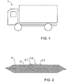
- FIG 1 shows a schematic side view of a utility vehicle 1 according to an embodiment of the invention.
- the utility vehicle 1 is shown by way of example as a transporter truck.
- the utility vehicle 1 can also be z.
- B. be a tractor-trailer, a tractor unit, a semi-trailer and any other type of truck or trailer and also a bus.
- the utility vehicle 1 initially comprises a compressed gas system (not shown) in the usual way.
- a special feature of the compressed gas system is that it is equipped with at least one, in Figure 2 shown pressurized gas container 2 is equipped.
- Figure 2 shows a schematic side view of the compressed gas container 2.
- the compressed gas container 2 is essentially hose-shaped or tubular, is used to receive compressed gas and has a filling connection 2.1 for supplying compressed gas and two discharge connections 2.2 and 2.3 for discharging compressed gas.
- the pressurized gas container 2 per se, including its envelope surface, is not made of metal or steel, but rather is made of a slack, flexible synthetic fabric G material.
- the filling and discharging connections 2.1, 2.2 and 2.3 and possibly other functional components of the pressurized gas container 2 can of course continue to be made of metal, steel or other suitable materials.
- the fabric material G is designed for a pressure of at least approximately 12.5 bar in order to be able to meet the requirements within the commercial vehicle pressurized gas system.
- the filling connection 2.1 for supplying compressed gas is connected to a motor compressor, not shown, of the utility vehicle 1, which is used to apply pressure to the gas and thus to generate the compressed gas.
- the compressed gas container 2 is connected to two auxiliary units (not shown) of the commercial vehicle 1 via the two discharge connections 2.2 and 2.3 for the compressed gas discharge (e.g. a brake system of the commercial vehicle 1, an auxiliary steering device of the commercial vehicle 1, a power steering of the commercial vehicle 1, a brake booster of the Commercial vehicle 1, an air conditioning system of the commercial vehicle 1, etc.) in order to supply them with compressed gas.
- the compressed gas discharge e.g. a brake system of the commercial vehicle 1, an auxiliary steering device of the commercial vehicle 1, a power steering of the commercial vehicle 1, a brake booster of the Commercial vehicle 1, an air conditioning system of the commercial vehicle 1, etc.
- the filling connection 2.1 is provided with a threaded ring to which an adapter for a quick-release fastener of a pressurized gas supply line can be screwed.
- the discharge connections 2.2 and 2.3 are also provided with threaded rings, onto which adapters for a quick-release fastener of a compressed gas discharge line can be screwed.
- the pressurized gas container 2 is designed so that it stores pressurized gas and can maintain the overpressure in its interior for a predefined period of time when the utility vehicle 1 is stationary.
- the volume of the pressurized gas supply of the pressurized gas container 2 is expediently made variable and can, for. B. according to the average gas requirement of the connected commercial vehicle ancillary units.
- the in Figure 2 The pressurized gas container 2 shown is made entirely of fabric material G and can expediently act as a noise curtain depending on the material.
- the utility vehicle 1 shown comprises a conventional vehicle frame which has two longitudinal members. Suitable mounting positions of one or more pressurized gas containers 2 are, for example: The installation space between the two longitudinal members, e.g. B. laterally next to a drive axle of the commercial vehicle 1, below at least one of the two longitudinal members, above at least one of the two longitudinal members, a driver's cab, in particular its rear wall or roof spoiler, a commercial vehicle apron or a bumper of the commercial vehicle 1, etc ..
- the gas used is preferably air and thus the compressed gas expediently corresponds to compressed air.
- Figure 3 shows a schematic perspective view of a pressurized gas container 2 according to another embodiment of the invention.
- a special feature of the in Figure 3 The embodiment shown is that the pressurized gas container 2 is not designed in the shape of a hose or pipe, but rather in the shape of a pillow, in particular in the shape of a substantially rectangular or square pillow.
Landscapes
- Engineering & Computer Science (AREA)
- Mechanical Engineering (AREA)
- General Engineering & Computer Science (AREA)
- Transportation (AREA)
- Filling Or Discharging Of Gas Storage Vessels (AREA)
Description
- Die Erfindung betrifft ein Nutzfahrzeug, vorzugsweise einen Omnibus oder einen Lastkraftwagen, mit einem Druckgassystem, das zumindest einen Druckgasbehälter aufweist.
- Nutzfahrzeuge sind üblicherweise mit Druckluftsystemen ausgestattet, die einen oder mehrere Druckluftbehälter zur Aufnahme von Druckluft aufweisen. Die Druckluftbehälter sind üblicherweise aus Stahl gefertigt und weisen somit ein nicht unbeachtliches Gewicht auf.
EP 1 818 596 A1 offenbart einen Druckbehälter aus Kunststoff, insbesondere Druckluftbehälter für Bremskraftanlagen und pneumatische Hilfseinrichtungen an Lastkraftwagen, Trucks, Omnibussen, Schienenfahrzeugen oder an Feuerlöschanlagen und ein Verfahren zu seiner Herstellung. Der Druckluftbehälter zeichnet sich insbesondere dadurch aus, dass er mit Polkappen aus einen aus Kugelabschnitten zusammengesetzter oder als Rotationsellipsoid geformter mehrlagiger Körper ausgebildet ist, wobei das Verhältnis aus Polkappenradius und Radius des Mantelmittenbereichs des Druckbehälters ein Verhältnis von mindestens 1:2,5 bis 1:5 erreicht, wobei die Wand der Polkappen und die Wand des Mantelmittelbereichs unter gleicher Krümmung ansatzlos ineinander übergehen. Der Druckluftbehälter wird zu einem Körper aus zusammengesetzten Kugelabschnitten oder als Rotationsellipsoidkörper mit einem Polkappenradius-/Mantelradius-Verhältnis von mindestens 1:2,5 bis 1:5 in den Arbeitschritten Spritzen des Liners, Aufschweißen der Armierungsschichten beim Bewickeln auf den Liner und Umspritzen des armierten Liners geformt wird. Zum Stand der Technik sind ferner dieWO 2013/030857 A und dieUS 2009/304308 A1 zu nennen. - Eine Aufgabe der Erfindung ist es, ein Nutzfahrzeug mit einem Druckgasbehälter zu schaffen, der einerseits leichtgewichtig und andererseits zugleich für den Einsatz in einem Nutzfahrzeug-Druckgassystem geeignet ist.
- Diese Aufgabe kann mit den Merkmalen des unabhängigen Anspruchs gelöst werden. Vorteilhafte Weiterbildungen der Erfindung sind in den Unteransprüchen und der nachfolgenden Beschreibung offenbart.
- Die Erfindung schafft ein Nutzfahrzeug, vorzugsweise einen Omnibus oder einen Lastkraftwagen, mit einem Druckgassystem, das zumindest einen Druckgasbehälter aufweist, der zur Aufnahme von Druckgas dient und zumindest einen Befüllanschluss zur Druckgas-Zuführung und Entladeanschlüsse zur Druckgas-Entladung umfasst. Der Druckgasbehälter zeichnet sich insbesondere dadurch aus, dass er gänzlich aus Gewebematerial hergestellt ist. Das verwendete Gewebematerial ist zweckmäßig einerseits relativ leichtgewichtig und andererseits relativ kostengünstig. Das Gewebematerial ist zweckmäßig ferner flexibel in der Geometrie.
- Das Gewebematerial ist vorzugsweise ein flexibles Gewebematerial und/oder ein Gewebe-Synthetikmaterial.
- Erfindungsgemäß ist der Druckgasbehälter gänzlich aus dem Gewebematerial hergestellt. Funktionskomponenten des Druckgasbehälters (z.B. die Befüll- und Entladeanschlüsse, Schnittstellen, Befestigungsmaßnahmen, etc.) können im Rahmen der Erfindung zweckmäßig natürlich aus Metall, Stahl oder anderen geeigneten Materialien ausgeführt sein.
- Der Druckgasbehälter kann zweckmäßig materialbedingt ferner als Geräuschschürze und/oder Akustikabschirmmaßnahme dienen.
- Zu erwähnen ist, dass im Rahmen der Erfindung insbesondere die zweckmäßig äußere Hüllfläche des Druckgasbehälters aus Gewebematerial hergestellt ist.
- Es ist möglich, dass der Druckgasbehälter für einen Druck von bis zumindest 7,5 bar, 10 bar, 12, 5 bar oder bis zumindest 15 bar ausgelegt ist.
- Der Druckgasbehälter ist mit zumindest einem Nebenaggregat des Nutzfahrzeugs, vorzugsweise einer Bremsvorrichtung des Nutzfahrzeugs, verbunden, um das zumindest eine Nebenaggregat mit Druckgas zu versorgen.
- Es ist möglich, dass der Druckgasbehälter zumindest zwei, zumindest drei, zumindest vier, zumindest fünf oder sogar zumindest sechs Entladeanschlüsse zur Druckgas-Entladung aufweist. Alternativ oder ergänzend kann der Druckgasbehälter mit zumindest zwei, zumindest drei, zumindest vier, zumindest fünf oder sogar zumindest sechs Nebenaggregaten des Nutzfahrzeugs zweckmäßig über die zuvor genannten Entladeanschlüsse verbunden sein, um sie mit Druckgas zu versorgen.
- Der Druckgasbehälter kann z. B. mit einem Motorkompressor, der zur Erzeugung des Druckgases dient, verbunden sein. Ebenso kann der Druckgasbehälter mit einem Antriebsmotor verbunden sein, der zur Erzeugung des Druckgases genutzt wird (z. B. Gasentnahme an einem Zylinder). Die Erzeugung des Druckgases ist somit nicht auf einen Motorkompressor beschränkt, sondern kann z.B. auch durch einen Antriebsmotor erfolgen.
- Der Druckgasbehälter kann geometrisch schlauch- oder rohrförmig (z. B. im Wesentlichen kreiszylinderförmig) oder kissenförmig (z. B. im Wesentlichen rechteck- oder quadratkissenförmig) ausgebildet sein.
- Der zumindest eine Befüllanschluss und/oder der zumindest eine Entladeanschluss können mit einem Gewindering versehen sein, an den ein Adapter für einen Schnellverschluss einer Druckgasleitung anschraubbar ist.
- Der Druckgasbehälter dient zweckmäßig dazu, Druckgas zu speichern, und während eines Stillstands den Überdruck in seinem Innern über eine vordefinierte Zeitdauer aufrecht zu erhalten.
- Es ist möglich, dass das Volumen der Druckgas-Bevorratung des Druckgasbehälters variabel ist und sich z. B. nach dem durchschnittlichen Gasbedarf der zumindest einen angeschlossenen, mit Druckgas zu versorgenden Nutzfahrzeug-Komponente, insbesondere zumindest einem Nebenaggregat, richtet.
- Das Nutzfahrzeug kann zunächst auf übliche Weise einen zwei Längsträger umfassenden Fahrzeugrahmen aufweisen. Zumindest ein Druckgasbehälter kann z. B. zwischen den zwei Längsträgern, unterhalb zumindest einem der zwei Längsträger und/oder oberhalb zumindest einem der zwei Längsträger angeordnet werden.
- Ein Druckgasbehälter kann ferner an einer Fahrerkabine des Nutzfahrzeugs, insbesondere deren Rückwand und/oder deren Dachspoiler, angeordnet werden.
- Ein Druckgasbehälter kann ebenso an oder in einer Schürze oder an oder in einem Stoßfänger des Nutzfahrzeugs angeordnet werden.
- Es ist möglich, dass der Druckgasbehälter über zumindest eine Rohrschellen-Befestigungseinrichtung an das Nutzfahrzeug montiert ist.
- Als Gas wird vorzugsweise Luft eingesetzt, so dass das Druckgas zweckmäßig Druckluft ist. Die Erfindung ist allerdings nicht auf das Medium Luft beschränkt, sondern umfasst als Medium auch andere gasförmige Stoffe.
- Die oben beschriebenen bevorzugten Ausführungsformen der Erfindung sind beliebig miteinander kombinierbar. Andere vorteilhafte Weiterbildungen der Erfindung sind in den Unteransprüchen offenbart oder ergeben sich aus der folgenden Beschreibung bevorzugter Ausführungsformen der Erfindung in Verbindung mit den beigefügten Figuren.
- Figur 1
- zeigt eine schematische Seitenansicht eines Nutzfahrzeugs gemäß einer Ausführungsform der Erfindung,
- Figur 2
- zeigt eine schematische Seitenansicht eines Druckgasbehälters gemäß einer Ausführungsform der Erfindung,
- Figur 3
- zeigt eine schematische Perspektivansicht eines Druckgasbehälters gemäß einer anderen Ausführungsform der Erfindung.
- Die in den Figuren gezeigten Ausführungsformen der Erfindung stimmen teilweise überein, wobei ähnliche oder identische Teile mit den gleichen Bezugszeichen versehen sind, und zu deren Erläuterung auch auf die Beschreibung der anderen Ausführungsform verwiesen wird, um Wiederholungen zu vermeiden.
-
Figur 1 zeigt eine schematische Seitenansicht eines Nutzfahrzeugs 1 gemäß einer Ausführungsform der Erfindung. Das Nutzfahrzeug 1 ist beispielhaft als Transporter-Lastkraftwagen dargestellt. Das Nutzfahrzeug 1 kann im Rahmen der Erfindung aber ebenso z. B. ein Sattelzug, eine Sattelzugmaschine, ein Sattelanhänger und jedweder andere Lastkraftwagen- oder Anhänger-Typ sein und ebenso ein Omnibus. Das Nutzfahrzeug 1 umfasst zunächst auf übliche Weise ein nicht dargestelltes Druckgassystem. Eine Besonderheit des Druckgassystems ist, dass es mit zumindest einem, inFigur 2 gezeigten Druckgasbehälter 2 ausgestattet ist. -
Figur 2 zeigt eine schematische Seitenansicht des Druckgasbehälters 2. Der Druckgasbehälter 2 ist im Wesentlichen schlauch- oder rohrförmig ausgebildet, dient zur Aufnahme von Druckgas und weist einen Befüllanschluss 2.1 zur Druckgas-Zuführung und zwei Entladeanschlüsse 2.2 und 2.3 zur Druckgas-Entladung auf. Der Druckgasbehälter 2 per se, einschließlich dessen Hüllfläche, ist nicht aus Metall oder Stahl gefertigt, sondern aus einem schlaffen, flexiblen Gewebe-Synthetikmaterial G ausgebildet. Die Befüll- und Entladeanschlüsse 2.1, 2.2 und 2.3 und ggf. andere Funktionskomponenten des Druckgasbehälters 2 können zweckmäßig natürlich weiterhin aus Metall, Stahl oder anderen geeigneten Materialien hergestellt sein. - Das Gewebematerial G ist für einen Druck von bis zumindest ungefähr 12,5 bar ausgelegt, um den Anforderungen innerhalb des Nutzfahrzeug-Druckgassystems gerecht werden zu können.
- Der Befüllanschluss 2.1 zur Druckgas-Zuführung ist mit einem nicht gezeigten Motorkompressor des Nutzfahrzeugs 1 verbunden, der dazu dient, das Gas mit Druck zu beaufschlagen und somit das Druckgas zu erzeugen.
- Der Druckgasbehälter 2 ist über die zwei Entladeanschlüsse 2.2 und 2.3 zur Druckgas-Entladung mit zwei nicht gezeigten Nebenaggregaten des Nutzfahrzeugs 1 verbunden (z. B. einem Bremssystem des Nutzfahrzeugs 1, einer Hilfslenkeinrichtung des Nutzfahrzeugs 1, einer Servolenkung des Nutzfahrzeugs 1, einem Bremskraftverstärker des Nutzfahrzeugs 1, einer Klimaanlage des Nutzfahrzeugs 1, etc.), um sie mit Druckgas zu versorgen.
- Der Befüllanschluss 2.1 ist mit einem Gewindering versehen, an den ein Adapter für einen Schnellverschluss einer Druckgas-Zuführleitung anschraubbar ist. Die Entladeanschlüsse 2.2 und 2.3 sind ebenso mit Gewinderingen versehen, an die Adapter für einen Schnellverschluss einer Druckgas-Abführleitung anschraubbar sind.
- Der Druckgasbehälter 2 ist so ausgeführt, dass er Druckgas speichert und während eines Stillstands des Nutzfahrzeugs 1 den Überdruck in seinem Innern über eine vordefinierte Zeitdauer aufrecht erhalten kann.
- Das Volumen der Druckgas-Bevorratung des Druckgasbehälters 2 ist zweckmäßig variabel ausgeführt und kann sich z. B. nach dem durchschnittlichen Gasbedarf der angeschlossenen Nutzfahrzeug-Nebenaggregate richten.
- Der in
Figur 2 gezeigte Druckgasbehälter 2 ist insgesamt aus Gewebematerial G gefertigt und kann zweckmäßig materialbedingt als Geräuschschürze wirken. - Das in
Figur 1 gezeigte Nutzfahrzeug 1 umfasst einen herkömmlichen Fahrzeugrahmen, der zwei Längsträger aufweist. Geeignete Montageposition eines oder mehrerer Druckgasbehälter 2 sind z.B.: Der Bauraum zwischen den zwei Längsträgern, z. B. seitlich neben einer Antriebsachse des Nutzfahrzeugs 1, unterhalb zumindest einem der zwei Längsträger, oberhalb zumindest einem der zwei Längsträger, eine Fahrerkabine, insbesondere deren Rückwand oder Dachspoiler, eine Nutzfahrzeug-Schürze oder ein Stoßfänger des Nutzfahrzeugs 1, etc.. - Zu erwähnen ist, dass als Gas vorzugsweise Luft eingesetzt wird und somit das Druckgas zweckmäßig Druckluft entspricht.
-
Figur 3 zeigt eine schematische Perspektivansicht eines Druckgasbehälters 2 gemäß einer anderen Ausführungsform der Erfindung. Eine Besonderheit der inFigur 3 gezeigten Ausführungsform ist, dass der Druckgasbehälter 2 nicht schlauch- oder rohrförmig ausgebildet ist, sondern kissenförmig, insbesondere im Wesentlichen rechteck- oder quadratkissenförmig. - Die Erfindung ist nicht auf die oben beschriebenen bevorzugten Ausführungsformen beschränkt. Vielmehr ist eine Vielzahl von Varianten und Abwandlungen möglich, die ebenfalls von dem Erfindungsgedanken Gebrauch machen und deshalb in den Schutzbereich fallen.
Claims (14)
- Nutzfahrzeug (1), vorzugsweise Omnibus oder Lastkraftwagen, mit einem Druckgassystem, das zumindest einen Druckgasbehälter (2) aufweist, der zur Aufnahme von Druckgas dient, wobei der Druckgasbehälter zumindest einen Befüllanschluss (2.1) zur Druckgas-Zuführung und Entladeanschlüsse zur Druckgas-Entladung (2.2, 2.3) umfasst,
dadurch gekennzeichnet, dass der Druckgasbehälter (2) gänzlich aus flexiblem Gewebematerial (G) hergestellt ist und der Druckgasbehälter (2) mit zumindest einem Nebenaggregat des Nutzfahrzeugs (1) verbunden ist, um das Nebenaggregat mit Druckgas zu versorgen. - Nutzfahrzeug (1) nach Anspruch 1, dadurch gekennzeichnet, dass das Gewebematerial (G) ein Synthetikmaterial ist.
- Nutzfahrzeug (1) nach einem der vorhergehenden Ansprüche, dadurch gekennzeichnet, dass der Druckgasbehälter (2) als Geräuschschürze dient.
- Nutzfahrzeug (1) nach einem der vorhergehenden Ansprüche, dadurch gekennzeichnet, dass der Druckgasbehälter (2) für einen Druck von bis zumindest 7,5 bar, 10 bar, 12,5 bar oder 15 bar ausgelegt ist.
- Nutzfahrzeug (1) nach einem der vorhergehenden Ansprüche, dadurch gekennzeichnet, dass das zumindest eine Nebenaggregat des Nutzfahrzeugs (1) eine Bremsvorrichtung des Nutzfahrzeugs (1) ist.
- Nutzfahrzeug (1) nach einem der vorhergehenden Ansprüche, dadurch gekennzeichnet, dass- der Druckgasbehälter (2) zumindest zwei, zumindest drei, zumindest vier, zumindest fünf oder zumindest sechs Entladeanschlüsse (2.2, 2.3) zur Druckgas-Entladung aufweist, und/oder- der Druckgasbehälter (2) mit zumindest zwei, zumindest drei, zumindest vier, zumindest fünf oder zumindest sechs Nebenaggregaten des Nutzfahrzeugs (1) verbunden ist, um sie mit Druckgas zu versorgen.
- Nutzfahrzeug (1) nach einem der vorhergehenden Ansprüche, dadurch gekennzeichnet, dass der Druckgasbehälter (2) mit einem Motorkompressor zur Erzeugung des Druckgases verbunden ist oder mit einem Motor, der zur Druckgaserzeugung genutzt wird.
- Nutzfahrzeug (1) nach einem der vorhergehenden Ansprüche, dadurch gekennzeichnet, dass das Gewebematerial (G) eine schlauch- oder rohrförmige oder rechteck- oder quadratkissenförmige Geometrie erzeugt.
- Nutzfahrzeug (1) nach einem der vorhergehenden Ansprüche, dadurch gekennzeichnet, dass der zumindest eine Befüllanschluss (2.1) und/oder zumindest ein Entladeanschluss (2.2, 2.3) mit einem Gewindering versehen ist, an den ein Adapter für einen Schnellverschluss einer Druckgasleitung anschraubbar ist.
- Nutzfahrzeug (1) nach einem der vorhergehenden Ansprüche, dadurch gekennzeichnet, dass der Druckgasbehälter (2) Druckgas speichert und während eines Stillstands des Nutzfahrzeugs (1) den Überdrück in seinem Innern über eine vordefinierte Zeitdauer aufrecht erhält.
- Nutzfahrzeug (1) nach einem der vorhergehenden Ansprüche, dadurch gekennzeichnet, dass das Volumen der Druckgas-Bevorratung des Druckgasbehälters (2) variabel ist und sich nach dem durchschnittlichen Gasbedarf der zumindest einen angeschlossenen, mit Druckgas zu versorgenden Nutzfahrzeug-Komponente richtet.
- Nutzfahrzeug (1) nach einem der vorhergehenden Ansprüche, dadurch gekennzeichnet, dass das Nutzfahrzeug (1) einen zwei Längsträger umfassenden Fahrzeugrahmen umfasst und zumindest ein Druckgasbehälter (2) zwischen den zwei Längsträgern, unterhalb zumindest einem der zwei Längsträger und/oder oberhalb zumindest einem der zwei Längsträger angeordnet ist.
- Nutzfahrzeug (1) nach einem der vorhergehenden Ansprüche, dadurch gekennzeichnet, dass zumindest ein Druckgasbehälter (2) an einer Fahrerkabine des Nutzfahrzeugs (1), insbesondere deren Rückwand oder Dachspoiler, angeordnet ist.
- Nutzfahrzeug (1) nach einem der vorhergehenden Ansprüche, dadurch gekennzeichnet, dass ein Druckgasbehälter (2) an oder in einer Schürze oder einem Stoßfänger des Nutzfahrzeugs (1) angeordnet ist.
Applications Claiming Priority (1)
| Application Number | Priority Date | Filing Date | Title |
|---|---|---|---|
| ATA814/2013A AT515036A1 (de) | 2013-10-22 | 2013-10-22 | Nutzfahrzeug mit Druckgasbehälter |
Publications (2)
| Publication Number | Publication Date |
|---|---|
| EP2876352A1 EP2876352A1 (de) | 2015-05-27 |
| EP2876352B1 true EP2876352B1 (de) | 2021-01-20 |
Family
ID=51389843
Family Applications (1)
| Application Number | Title | Priority Date | Filing Date |
|---|---|---|---|
| EP14002812.7A Active EP2876352B1 (de) | 2013-10-22 | 2014-08-12 | Nutzfahrzeug mit Druckgasbehälter |
Country Status (2)
| Country | Link |
|---|---|
| EP (1) | EP2876352B1 (de) |
| AT (1) | AT515036A1 (de) |
Families Citing this family (2)
| Publication number | Priority date | Publication date | Assignee | Title |
|---|---|---|---|---|
| AT514949B1 (de) * | 2013-12-18 | 2015-05-15 | MAN Truck & Bus Österreich AG | Kraftfahrzeug, insbesondere Nutzfahrzeug, mit wenigstens einem Luftspeicherbehälter einer Luftversorgung |
| DE102016220037B4 (de) * | 2016-10-14 | 2019-03-14 | Ford Global Technologies, Llc | Druckabgreifvorrichtung und Kraftfahrzeug mit Druckabgreifvorrichtung sowie Druckabgreifverfahren |
Citations (4)
| Publication number | Priority date | Publication date | Assignee | Title |
|---|---|---|---|---|
| EP1300308A2 (de) * | 2001-10-04 | 2003-04-09 | BPW Bergische Achsen Kommanditgesellschaft | Verfahren zum Betrieb einer druckluftbetriebenen Bremsanlage eines Fahrzeugverbandes sowie Zugfahrzeug mit druckluftbetriebener Bremsanlage |
| US20090304308A1 (en) * | 2008-06-06 | 2009-12-10 | Utilequip, Inc. | Flexible Fabric Shipping and Dispensing Container |
| WO2013030857A1 (en) * | 2011-09-02 | 2013-03-07 | AERO SEKUR S.p.a | Security system for a pneumatic accumulator and plant using said system |
| WO2013083652A2 (en) * | 2011-12-05 | 2013-06-13 | Blue Wave Co S.A. | Pressure vessel for fuel applications |
Family Cites Families (13)
| Publication number | Priority date | Publication date | Assignee | Title |
|---|---|---|---|---|
| GB117343A (en) * | 1917-09-15 | 1918-07-18 | Richard Carlile Jagger | Improvements in and relating to Gas Containers for Motor Driven Vehicles. |
| US3174722A (en) * | 1962-09-17 | 1965-03-23 | Erhard J Alm | Load lifting device |
| DE2038146A1 (de) * | 1970-07-31 | 1972-02-10 | Graubremse Gmbh | Druckluftbremsanlage fuer Motorwagen und Anhaenger |
| DE2405788A1 (de) * | 1974-02-07 | 1975-08-21 | Holger Rohr | Verfahren und vorrichtung zum heben von lasten |
| JPS579698A (en) * | 1980-05-19 | 1982-01-19 | Goodyear Aerospace Corp | Air pressure working lift-pad |
| DE3739490A1 (de) * | 1987-11-21 | 1989-06-01 | Walter Ziegler | Besonders gearteter kugelfoermiger, aufblasbarer ballon bzw. behaelter zur aufnahme und zum lagern von pressluft und komprimierten gasen |
| US6796421B2 (en) * | 2001-05-23 | 2004-09-28 | Stan A. Sanders | Flexible pressure vessel, apparatus and method for making same |
| CN100430301C (zh) * | 2002-09-17 | 2008-11-05 | 亚历山大·S·波奇察雷夫 | 多层压力容器及其制造方法 |
| JP4825209B2 (ja) * | 2004-09-04 | 2011-11-30 | ミドルゲート マーケティング リミテッド | 荷役装置およびそのための膨張バッグ、ならびに可動式の荷台を組み入れた車両およびトレーラ |
| DE102004046352B4 (de) * | 2004-09-24 | 2010-02-25 | Daimler Ag | Druckluft-Versorgungseinrichtung für eine Druckluftanlage in einem Nutzfahrzeug |
| DE102006006902B4 (de) * | 2006-02-09 | 2008-02-21 | Gräfenthaler Kunststofftechnik GmbH | Druckbehälter aus Kunststoff und Verfahren zu seiner Herstellung |
| DE102010043645B4 (de) * | 2010-11-09 | 2012-12-06 | Deutsches Zentrum für Luft- und Raumfahrt e.V. | Drucktankverbund |
| DE102011000674B4 (de) * | 2011-02-11 | 2022-02-17 | Martin Markert | Druckbehälter für Gase |
-
2013
- 2013-10-22 AT ATA814/2013A patent/AT515036A1/de unknown
-
2014
- 2014-08-12 EP EP14002812.7A patent/EP2876352B1/de active Active
Patent Citations (4)
| Publication number | Priority date | Publication date | Assignee | Title |
|---|---|---|---|---|
| EP1300308A2 (de) * | 2001-10-04 | 2003-04-09 | BPW Bergische Achsen Kommanditgesellschaft | Verfahren zum Betrieb einer druckluftbetriebenen Bremsanlage eines Fahrzeugverbandes sowie Zugfahrzeug mit druckluftbetriebener Bremsanlage |
| US20090304308A1 (en) * | 2008-06-06 | 2009-12-10 | Utilequip, Inc. | Flexible Fabric Shipping and Dispensing Container |
| WO2013030857A1 (en) * | 2011-09-02 | 2013-03-07 | AERO SEKUR S.p.a | Security system for a pneumatic accumulator and plant using said system |
| WO2013083652A2 (en) * | 2011-12-05 | 2013-06-13 | Blue Wave Co S.A. | Pressure vessel for fuel applications |
Also Published As
| Publication number | Publication date |
|---|---|
| AT515036A1 (de) | 2015-05-15 |
| EP2876352A1 (de) | 2015-05-27 |
Similar Documents
| Publication | Publication Date | Title |
|---|---|---|
| EP2794325B2 (de) | Nutzfahrzeuganhänger für strassenfahrzeuge, verwendung eines freiraums unterhalb einer ladefläche eines nutzfahrzeuganhängers, verfahren zum betreiben eines motorisierten nutzfahrzeugs und strassenfahrzeuggespann | |
| DE10046298B4 (de) | Verwendung eines Leichtbauwerkstoffs für den Crash-Schutz | |
| DE102017110905B4 (de) | Fahrzeug mit modularer Kraftstoffeinfüllstutzenanordnung | |
| DE102020103684A1 (de) | Energieabsorbierende dichtung für ein fahrzeug | |
| DE102007052246A1 (de) | Airbag, insbesondere für einen Kraftwagen | |
| EP1419876A2 (de) | Verfahren und Vorrichtung zum Abdichten und Aufpumpen von Reifen bei Pannen sowie Dichtmittelbehälter als auch Adapter hierfür | |
| DE102014110880A1 (de) | Harnstofflösung-Vorrichtung für Fahrzeuge | |
| DE102011114298A1 (de) | Kraftfahrzeug mit einem Bremselement | |
| DE102012022809B4 (de) | Trennwandanordnung für ein Fahrzeug | |
| DE102014207555A1 (de) | Anordnung von Komponenten im Bereich einer Hinterachse eines zweispurigen, zumindest teilweise alternativ antreibbaren Kraftfahrzeugs, Hinterachsträger, Druckbehälter sowie zweispuriges Kraftfahrzeug | |
| EP2876352B1 (de) | Nutzfahrzeug mit Druckgasbehälter | |
| DE102012201219B4 (de) | Luftleitelement | |
| EP1380462A2 (de) | Befestigungsvorrichtung für Behälter | |
| WO2012084086A1 (de) | Verfahren zum herstellen von kraftwagen und kraftwagen | |
| DE102006046355A1 (de) | Fahrzeug mit Auftriebskörper | |
| WO2001021468A1 (de) | Fahrzeug für lasten- und personentransporte | |
| EP3653449B1 (de) | Aufprallschutzvorrichtung | |
| DE3211537A1 (de) | Tank fuer unter druck stehende medien | |
| DE102012013605A1 (de) | Kraftwagen mit Tragrahmen und Aufbau | |
| DE19953983A1 (de) | Frontverkleidung für Fahrzeuge insbesondere Strassenfahrzeuge | |
| DE10259204B4 (de) | Kraftstoffreservoir und Verfahren zur Herstellung eines Kraftstoffreservoirs | |
| DE102006059991A1 (de) | Personenkraftwagen | |
| DE102010019827A1 (de) | Dachanordnung für einen Kraftwagen und Verfahren zu deren Herstellung | |
| DE60316343T2 (de) | Stossdämpfender schutz für insassen | |
| DE102016012630A1 (de) | Zugfahrzeug |
Legal Events
| Date | Code | Title | Description |
|---|---|---|---|
| PUAI | Public reference made under article 153(3) epc to a published international application that has entered the european phase |
Free format text: ORIGINAL CODE: 0009012 |
|
| 17P | Request for examination filed |
Effective date: 20140812 |
|
| AK | Designated contracting states |
Kind code of ref document: A1 Designated state(s): AL AT BE BG CH CY CZ DE DK EE ES FI FR GB GR HR HU IE IS IT LI LT LU LV MC MK MT NL NO PL PT RO RS SE SI SK SM TR |
|
| AX | Request for extension of the european patent |
Extension state: BA ME |
|
| R17P | Request for examination filed (corrected) |
Effective date: 20150505 |
|
| STAA | Information on the status of an ep patent application or granted ep patent |
Free format text: STATUS: EXAMINATION IS IN PROGRESS |
|
| 17Q | First examination report despatched |
Effective date: 20180622 |
|
| RIC1 | Information provided on ipc code assigned before grant |
Ipc: F17C 1/14 20060101ALN20200713BHEP Ipc: F17C 1/16 20060101AFI20200713BHEP |
|
| GRAP | Despatch of communication of intention to grant a patent |
Free format text: ORIGINAL CODE: EPIDOSNIGR1 |
|
| STAA | Information on the status of an ep patent application or granted ep patent |
Free format text: STATUS: GRANT OF PATENT IS INTENDED |
|
| INTG | Intention to grant announced |
Effective date: 20200914 |
|
| GRAS | Grant fee paid |
Free format text: ORIGINAL CODE: EPIDOSNIGR3 |
|
| GRAA | (expected) grant |
Free format text: ORIGINAL CODE: 0009210 |
|
| STAA | Information on the status of an ep patent application or granted ep patent |
Free format text: STATUS: THE PATENT HAS BEEN GRANTED |
|
| AK | Designated contracting states |
Kind code of ref document: B1 Designated state(s): AL AT BE BG CH CY CZ DE DK EE ES FI FR GB GR HR HU IE IS IT LI LT LU LV MC MK MT NL NO PL PT RO RS SE SI SK SM TR |
|
| REG | Reference to a national code |
Ref country code: GB Ref legal event code: FG4D Free format text: NOT ENGLISH |
|
| REG | Reference to a national code |
Ref country code: CH Ref legal event code: EP |
|
| REG | Reference to a national code |
Ref country code: DE Ref legal event code: R096 Ref document number: 502014015206 Country of ref document: DE |
|
| REG | Reference to a national code |
Ref country code: AT Ref legal event code: REF Ref document number: 1356717 Country of ref document: AT Kind code of ref document: T Effective date: 20210215 |
|
| REG | Reference to a national code |
Ref country code: IE Ref legal event code: FG4D Free format text: LANGUAGE OF EP DOCUMENT: GERMAN |
|
| REG | Reference to a national code |
Ref country code: NL Ref legal event code: FP |
|
| REG | Reference to a national code |
Ref country code: SE Ref legal event code: TRGR |
|
| REG | Reference to a national code |
Ref country code: LT Ref legal event code: MG9D |
|
| PG25 | Lapsed in a contracting state [announced via postgrant information from national office to epo] |
Ref country code: LT Free format text: LAPSE BECAUSE OF FAILURE TO SUBMIT A TRANSLATION OF THE DESCRIPTION OR TO PAY THE FEE WITHIN THE PRESCRIBED TIME-LIMIT Effective date: 20210120 Ref country code: PT Free format text: LAPSE BECAUSE OF FAILURE TO SUBMIT A TRANSLATION OF THE DESCRIPTION OR TO PAY THE FEE WITHIN THE PRESCRIBED TIME-LIMIT Effective date: 20210520 Ref country code: HR Free format text: LAPSE BECAUSE OF FAILURE TO SUBMIT A TRANSLATION OF THE DESCRIPTION OR TO PAY THE FEE WITHIN THE PRESCRIBED TIME-LIMIT Effective date: 20210120 Ref country code: FI Free format text: LAPSE BECAUSE OF FAILURE TO SUBMIT A TRANSLATION OF THE DESCRIPTION OR TO PAY THE FEE WITHIN THE PRESCRIBED TIME-LIMIT Effective date: 20210120 Ref country code: GR Free format text: LAPSE BECAUSE OF FAILURE TO SUBMIT A TRANSLATION OF THE DESCRIPTION OR TO PAY THE FEE WITHIN THE PRESCRIBED TIME-LIMIT Effective date: 20210421 Ref country code: BG Free format text: LAPSE BECAUSE OF FAILURE TO SUBMIT A TRANSLATION OF THE DESCRIPTION OR TO PAY THE FEE WITHIN THE PRESCRIBED TIME-LIMIT Effective date: 20210420 Ref country code: NO Free format text: LAPSE BECAUSE OF FAILURE TO SUBMIT A TRANSLATION OF THE DESCRIPTION OR TO PAY THE FEE WITHIN THE PRESCRIBED TIME-LIMIT Effective date: 20210420 |
|
| PG25 | Lapsed in a contracting state [announced via postgrant information from national office to epo] |
Ref country code: RS Free format text: LAPSE BECAUSE OF FAILURE TO SUBMIT A TRANSLATION OF THE DESCRIPTION OR TO PAY THE FEE WITHIN THE PRESCRIBED TIME-LIMIT Effective date: 20210120 Ref country code: PL Free format text: LAPSE BECAUSE OF FAILURE TO SUBMIT A TRANSLATION OF THE DESCRIPTION OR TO PAY THE FEE WITHIN THE PRESCRIBED TIME-LIMIT Effective date: 20210120 Ref country code: LV Free format text: LAPSE BECAUSE OF FAILURE TO SUBMIT A TRANSLATION OF THE DESCRIPTION OR TO PAY THE FEE WITHIN THE PRESCRIBED TIME-LIMIT Effective date: 20210120 |
|
| REG | Reference to a national code |
Ref country code: DE Ref legal event code: R081 Ref document number: 502014015206 Country of ref document: DE Owner name: MAN TRUCK & BUS SE, DE Free format text: FORMER OWNER: MAN TRUCK & BUS OESTERREICH AG, STEYR, AT |
|
| PG25 | Lapsed in a contracting state [announced via postgrant information from national office to epo] |
Ref country code: IS Free format text: LAPSE BECAUSE OF FAILURE TO SUBMIT A TRANSLATION OF THE DESCRIPTION OR TO PAY THE FEE WITHIN THE PRESCRIBED TIME-LIMIT Effective date: 20210520 |
|
| REG | Reference to a national code |
Ref country code: DE Ref legal event code: R097 Ref document number: 502014015206 Country of ref document: DE |
|
| RAP2 | Party data changed (patent owner data changed or rights of a patent transferred) |
Owner name: MAN TRUCK & BUS SE |
|
| PG25 | Lapsed in a contracting state [announced via postgrant information from national office to epo] |
Ref country code: SM Free format text: LAPSE BECAUSE OF FAILURE TO SUBMIT A TRANSLATION OF THE DESCRIPTION OR TO PAY THE FEE WITHIN THE PRESCRIBED TIME-LIMIT Effective date: 20210120 Ref country code: EE Free format text: LAPSE BECAUSE OF FAILURE TO SUBMIT A TRANSLATION OF THE DESCRIPTION OR TO PAY THE FEE WITHIN THE PRESCRIBED TIME-LIMIT Effective date: 20210120 Ref country code: CZ Free format text: LAPSE BECAUSE OF FAILURE TO SUBMIT A TRANSLATION OF THE DESCRIPTION OR TO PAY THE FEE WITHIN THE PRESCRIBED TIME-LIMIT Effective date: 20210120 |
|
| PLBE | No opposition filed within time limit |
Free format text: ORIGINAL CODE: 0009261 |
|
| STAA | Information on the status of an ep patent application or granted ep patent |
Free format text: STATUS: NO OPPOSITION FILED WITHIN TIME LIMIT |
|
| PG25 | Lapsed in a contracting state [announced via postgrant information from national office to epo] |
Ref country code: DK Free format text: LAPSE BECAUSE OF FAILURE TO SUBMIT A TRANSLATION OF THE DESCRIPTION OR TO PAY THE FEE WITHIN THE PRESCRIBED TIME-LIMIT Effective date: 20210120 Ref country code: ES Free format text: LAPSE BECAUSE OF FAILURE TO SUBMIT A TRANSLATION OF THE DESCRIPTION OR TO PAY THE FEE WITHIN THE PRESCRIBED TIME-LIMIT Effective date: 20210120 Ref country code: RO Free format text: LAPSE BECAUSE OF FAILURE TO SUBMIT A TRANSLATION OF THE DESCRIPTION OR TO PAY THE FEE WITHIN THE PRESCRIBED TIME-LIMIT Effective date: 20210120 Ref country code: SK Free format text: LAPSE BECAUSE OF FAILURE TO SUBMIT A TRANSLATION OF THE DESCRIPTION OR TO PAY THE FEE WITHIN THE PRESCRIBED TIME-LIMIT Effective date: 20210120 |
|
| 26N | No opposition filed |
Effective date: 20211021 |
|
| PG25 | Lapsed in a contracting state [announced via postgrant information from national office to epo] |
Ref country code: AL Free format text: LAPSE BECAUSE OF FAILURE TO SUBMIT A TRANSLATION OF THE DESCRIPTION OR TO PAY THE FEE WITHIN THE PRESCRIBED TIME-LIMIT Effective date: 20210120 |
|
| PG25 | Lapsed in a contracting state [announced via postgrant information from national office to epo] |
Ref country code: SI Free format text: LAPSE BECAUSE OF FAILURE TO SUBMIT A TRANSLATION OF THE DESCRIPTION OR TO PAY THE FEE WITHIN THE PRESCRIBED TIME-LIMIT Effective date: 20210120 |
|
| REG | Reference to a national code |
Ref country code: CH Ref legal event code: PL |
|
| PG25 | Lapsed in a contracting state [announced via postgrant information from national office to epo] |
Ref country code: MC Free format text: LAPSE BECAUSE OF FAILURE TO SUBMIT A TRANSLATION OF THE DESCRIPTION OR TO PAY THE FEE WITHIN THE PRESCRIBED TIME-LIMIT Effective date: 20210120 |
|
| REG | Reference to a national code |
Ref country code: BE Ref legal event code: MM Effective date: 20210831 |
|
| GBPC | Gb: european patent ceased through non-payment of renewal fee |
Effective date: 20210812 |
|
| PG25 | Lapsed in a contracting state [announced via postgrant information from national office to epo] |
Ref country code: LI Free format text: LAPSE BECAUSE OF NON-PAYMENT OF DUE FEES Effective date: 20210831 Ref country code: CH Free format text: LAPSE BECAUSE OF NON-PAYMENT OF DUE FEES Effective date: 20210831 |
|
| PG25 | Lapsed in a contracting state [announced via postgrant information from national office to epo] |
Ref country code: IS Free format text: LAPSE BECAUSE OF FAILURE TO SUBMIT A TRANSLATION OF THE DESCRIPTION OR TO PAY THE FEE WITHIN THE PRESCRIBED TIME-LIMIT Effective date: 20210520 Ref country code: LU Free format text: LAPSE BECAUSE OF NON-PAYMENT OF DUE FEES Effective date: 20210812 |
|
| PG25 | Lapsed in a contracting state [announced via postgrant information from national office to epo] |
Ref country code: IE Free format text: LAPSE BECAUSE OF NON-PAYMENT OF DUE FEES Effective date: 20210812 Ref country code: GB Free format text: LAPSE BECAUSE OF NON-PAYMENT OF DUE FEES Effective date: 20210812 Ref country code: BE Free format text: LAPSE BECAUSE OF NON-PAYMENT OF DUE FEES Effective date: 20210831 |
|
| REG | Reference to a national code |
Ref country code: AT Ref legal event code: MM01 Ref document number: 1356717 Country of ref document: AT Kind code of ref document: T Effective date: 20210812 |
|
| PG25 | Lapsed in a contracting state [announced via postgrant information from national office to epo] |
Ref country code: AT Free format text: LAPSE BECAUSE OF NON-PAYMENT OF DUE FEES Effective date: 20210812 |
|
| PG25 | Lapsed in a contracting state [announced via postgrant information from national office to epo] |
Ref country code: HU Free format text: LAPSE BECAUSE OF FAILURE TO SUBMIT A TRANSLATION OF THE DESCRIPTION OR TO PAY THE FEE WITHIN THE PRESCRIBED TIME-LIMIT; INVALID AB INITIO Effective date: 20140812 |
|
| PG25 | Lapsed in a contracting state [announced via postgrant information from national office to epo] |
Ref country code: CY Free format text: LAPSE BECAUSE OF FAILURE TO SUBMIT A TRANSLATION OF THE DESCRIPTION OR TO PAY THE FEE WITHIN THE PRESCRIBED TIME-LIMIT Effective date: 20210120 |
|
| REG | Reference to a national code |
Ref country code: NL Ref legal event code: PD Owner name: MAN TRUCK & BUS OESTERREICH GESMBH; AT Free format text: DETAILS ASSIGNMENT: CHANGE OF OWNER(S), ASSIGNMENT; FORMER OWNER NAME: MAN TRUCK & BUS OESTERREICH GESMBH Effective date: 20231031 |
|
| PG25 | Lapsed in a contracting state [announced via postgrant information from national office to epo] |
Ref country code: MK Free format text: LAPSE BECAUSE OF FAILURE TO SUBMIT A TRANSLATION OF THE DESCRIPTION OR TO PAY THE FEE WITHIN THE PRESCRIBED TIME-LIMIT Effective date: 20210120 |
|
| PG25 | Lapsed in a contracting state [announced via postgrant information from national office to epo] |
Ref country code: MT Free format text: LAPSE BECAUSE OF FAILURE TO SUBMIT A TRANSLATION OF THE DESCRIPTION OR TO PAY THE FEE WITHIN THE PRESCRIBED TIME-LIMIT Effective date: 20210120 |
|
| PGFP | Annual fee paid to national office [announced via postgrant information from national office to epo] |
Ref country code: NL Payment date: 20250825 Year of fee payment: 12 |
|
| PGFP | Annual fee paid to national office [announced via postgrant information from national office to epo] |
Ref country code: DE Payment date: 20250827 Year of fee payment: 12 |
|
| PGFP | Annual fee paid to national office [announced via postgrant information from national office to epo] |
Ref country code: IT Payment date: 20250825 Year of fee payment: 12 |
|
| PGFP | Annual fee paid to national office [announced via postgrant information from national office to epo] |
Ref country code: FR Payment date: 20250825 Year of fee payment: 12 |
|
| PGFP | Annual fee paid to national office [announced via postgrant information from national office to epo] |
Ref country code: SE Payment date: 20250825 Year of fee payment: 12 |
|
| PG25 | Lapsed in a contracting state [announced via postgrant information from national office to epo] |
Ref country code: TR Free format text: LAPSE BECAUSE OF FAILURE TO SUBMIT A TRANSLATION OF THE DESCRIPTION OR TO PAY THE FEE WITHIN THE PRESCRIBED TIME-LIMIT Effective date: 20210120 |