EP2876367A1 - Dispositif de génération de vapeur et dispositif de cuisson avec dispositif de génération de vapeur - Google Patents
Dispositif de génération de vapeur et dispositif de cuisson avec dispositif de génération de vapeur Download PDFInfo
- Publication number
- EP2876367A1 EP2876367A1 EP13820682.6A EP13820682A EP2876367A1 EP 2876367 A1 EP2876367 A1 EP 2876367A1 EP 13820682 A EP13820682 A EP 13820682A EP 2876367 A1 EP2876367 A1 EP 2876367A1
- Authority
- EP
- European Patent Office
- Prior art keywords
- water
- storage chamber
- steam
- water storage
- heating
- Prior art date
- Legal status (The legal status is an assumption and is not a legal conclusion. Google has not performed a legal analysis and makes no representation as to the accuracy of the status listed.)
- Granted
Links
Images


Classifications
-
- A—HUMAN NECESSITIES
- A47—FURNITURE; DOMESTIC ARTICLES OR APPLIANCES; COFFEE MILLS; SPICE MILLS; SUCTION CLEANERS IN GENERAL
- A47J—KITCHEN EQUIPMENT; COFFEE MILLS; SPICE MILLS; APPARATUS FOR MAKING BEVERAGES
- A47J27/00—Cooking-vessels
- A47J27/04—Cooking-vessels for cooking food in steam; Devices for extracting fruit juice by means of steam ; Vacuum cooking vessels
-
- A—HUMAN NECESSITIES
- A47—FURNITURE; DOMESTIC ARTICLES OR APPLIANCES; COFFEE MILLS; SPICE MILLS; SUCTION CLEANERS IN GENERAL
- A47J—KITCHEN EQUIPMENT; COFFEE MILLS; SPICE MILLS; APPARATUS FOR MAKING BEVERAGES
- A47J36/00—Parts, details or accessories of cooking-vessels
- A47J36/02—Selection of specific materials, e.g. heavy bottoms with copper inlay or with insulating inlay
- A47J36/027—Cooking- or baking-vessels specially adapted for use in microwave ovens; Accessories therefor
-
- F—MECHANICAL ENGINEERING; LIGHTING; HEATING; WEAPONS; BLASTING
- F22—STEAM GENERATION
- F22B—METHODS OF STEAM GENERATION; STEAM BOILERS
- F22B1/00—Methods of steam generation characterised by form of heating method
- F22B1/28—Methods of steam generation characterised by form of heating method in boilers heated electrically
- F22B1/281—Methods of steam generation characterised by form of heating method in boilers heated electrically other than by electrical resistances or electrodes
-
- F—MECHANICAL ENGINEERING; LIGHTING; HEATING; WEAPONS; BLASTING
- F22—STEAM GENERATION
- F22B—METHODS OF STEAM GENERATION; STEAM BOILERS
- F22B1/00—Methods of steam generation characterised by form of heating method
- F22B1/28—Methods of steam generation characterised by form of heating method in boilers heated electrically
- F22B1/284—Methods of steam generation characterised by form of heating method in boilers heated electrically with water in reservoirs
- F22B1/285—Methods of steam generation characterised by form of heating method in boilers heated electrically with water in reservoirs the water being fed by a pump to the reservoirs
-
- F—MECHANICAL ENGINEERING; LIGHTING; HEATING; WEAPONS; BLASTING
- F24—HEATING; RANGES; VENTILATING
- F24C—DOMESTIC STOVES OR RANGES ; DETAILS OF DOMESTIC STOVES OR RANGES, OF GENERAL APPLICATION
- F24C15/00—Details
- F24C15/32—Arrangements of ducts for hot gases, e.g. in or around baking ovens
- F24C15/322—Arrangements of ducts for hot gases, e.g. in or around baking ovens with forced circulation
- F24C15/327—Arrangements of ducts for hot gases, e.g. in or around baking ovens with forced circulation with air moisturising
-
- H—ELECTRICITY
- H05—ELECTRIC TECHNIQUES NOT OTHERWISE PROVIDED FOR
- H05B—ELECTRIC HEATING; ELECTRIC LIGHT SOURCES NOT OTHERWISE PROVIDED FOR; CIRCUIT ARRANGEMENTS FOR ELECTRIC LIGHT SOURCES, IN GENERAL
- H05B6/00—Heating by electric, magnetic or electromagnetic fields
- H05B6/64—Heating using microwaves
- H05B6/80—Apparatus for specific applications
- H05B6/802—Apparatus for specific applications for heating fluids
- H05B6/804—Water heaters, water boilers
-
- A—HUMAN NECESSITIES
- A47—FURNITURE; DOMESTIC ARTICLES OR APPLIANCES; COFFEE MILLS; SPICE MILLS; SUCTION CLEANERS IN GENERAL
- A47J—KITCHEN EQUIPMENT; COFFEE MILLS; SPICE MILLS; APPARATUS FOR MAKING BEVERAGES
- A47J27/00—Cooking-vessels
- A47J27/04—Cooking-vessels for cooking food in steam; Devices for extracting fruit juice by means of steam ; Vacuum cooking vessels
- A47J2027/043—Cooking-vessels for cooking food in steam; Devices for extracting fruit juice by means of steam ; Vacuum cooking vessels for cooking food in steam
Definitions
- the present invention relates to a steam generator which heats water to generate steam and a heating cooker including the steam generator.
- Patent Literature 1 JP 2008-164284 A
- the present invention is made to overcome the aforementioned issues in a conventional steam generator and aims at providing a steam generator which can prevent boiling water from ejecting from a steam spout port, by inhibiting running-up by the boiling water in the steam generating chamber.
- a steam generator includes: a water storage chamber which stores water; at least one heating portion which heats water in the water storage chamber to generate steam; a water supply device which supplies water into the water storage chamber; and a plurality of fins provided in the water storage chamber, wherein the water storage chamber has a steam spout port from which the steam generated by the heating portion spouts, wherein the plurality of fins extend along a steam-generating direction under the steam spout port, being separated with each other and crossing the heating portion.
- the plurality of fins extend along a steam-generating direction under the steam spout port, being separated with each other and crossing the heating portion.
- the fins can transmit heat in a vicinity of the heating portion, with a high temperature in particular, to the inside of the water in the water storage chamber, to which heat is less likely to be transmitted, and also the fins can increase a contact area between the water storage chamber and the water, thereby transmitting the heat from the heating portion to the water efficiently. Therefore, temperature of a contact portion between the water storage chamber and the water decreases, and thus large bubbles which may occur at high temperature are less likely to be generated.
- a steam generator includes: a water storage chamber which stores water; a heating portion which heats water in the water storage chamber to generate steam; and a water supply device which supplies water into the water storage chamber, wherein the water storage chamber is provided with a steam spout port from which the steam generated by the heating portion spouts, and wherein the at least one heating portion is provided each of above and under a water surface which emerges in the water storage chamber during heating.
- the heating portion arranged above the water surface heats the bubbles and changes them into steam, thereby preventing the boiling water from ejecting from the steam spout port.
- a first invention is a steam generator including: a water storage chamber which stores water; at least one heating portion which heats water in the water storage chamber to generate steam; a water supply device which supplies water into the water storage chamber; and a plurality of fins provided in the water storage chamber, wherein the water storage chamber has a steam spout port from which the steam generated by the heating portion spouts, and wherein the plurality of fins extend along a steam-generating direction under the steam spout port, being separated with each other and crossing the heating portion.
- the fins can transmit heat in a vicinity of the heating portion, with a high temperature in particular, to the inside of the water in the water storage chamber, to which heat is less likely to be transmitted, and also the fins can increase a contact area between the water storage chamber and the water, thereby transmitting the heat from the heating portion to the water efficiently.
- temperature of a contact portion between the water storage chamber and the water decreases, and thus large bubbles which may occur at high temperature are less likely to be generated. Therefore, running-up by boiling water due to burst of the large bubbles which have risen to the water surface can be reduced, and the boiling water can be prevented from ejecting from the steam spout port.
- the large bubbles are less likely to be generated, thereby reducing burst sound of the babbles.
- the temperature of the contact portion between the water storage chamber and the water can be decreased, thereby suppressing scale deposition which is likely to occur at higher temperature.
- the water storage chamber is finely partitioned by the fins, thereby reducing sizes of the bubbles during boiling physically. This can further reduce the large bubble generation.
- the fins are arranged along the steam-generating direction, thereby leading to unstopping of the steam flow. This can increase steam amount and steam flow rate.
- a third invention is the first or second invention, wherein the fins extend from a first side surface in the water storage chamber, and distal ends of the fins are spaced from a second side surface in the water storage chamber opposite to the first side surface.
- water can flow between the fins and the second side surface, thereby increasing the contact area between the water storage chamber and the water. This facilitates water convection, thereby achieving more uniform temperature distribution of the water in the water storage chamber.
- large bubble generation can be reduced, thereby inhibiting running-up by the boiling water and thus preventing the boiling water from ejecting from the steam spout port. Also, it is possible to reduce burst sound of the babbles.
- a fourth invention is any one of the first invention to the third invention, wherein the at least one heating portion is provided each of above and under a water surface which emerges in the water storage chamber during heating.
- the heating portion arranged above the water surface heats the bubbles and changes them into steam, thereby preventing the boiling water from ejecting from the steam spout port.
- a sixth invention is a heating cooker provided with the steam generator any one of the first invention to the fifth invention.
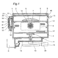
- Fig. 1 is a front cross-sectional view illustrating a heating cooker including a steam generator according to the first embodiment of the present invention.
- a wall surface forming the heat chamber 1 is grounded by electrical connection with an earth cable (not illustrated), and the rails 12 which are formed integrally with the heating chamber 1 are also grounded.
- the wall surface forming the heat chamber 1 according to the first embodiment is applied with a fluorine coating which can be easy to wipe off dirt, a porcelain enamel coating or other heat-resistant coatings can also be applied.
- a fluorine coating which can be easy to wipe off dirt
- a porcelain enamel coating or other heat-resistant coatings can also be applied.
- the aluminum-plated steel plate is used as a material of the heating chamber 1, other metallic materials such as a stainless steel material can also be used.
- the mounting plate 4 is formed by an aluminum-plated steel plate, and is formed to have a concavo-convex shape with press working to make oil and fat contents from the food 5 flow out.
- a fluorine coating is applied to a surface of the mounting plate 4, and a heat generating element which generates heat by absorbing microwaves is provided on a rear surface of the mounting plate 4. Accordingly, by providing the heat generating element on the rear surface of the mounting plate 4, the food 5 can be heated from both sides with combination of the heating chamber heater 2 located above the food 5 and the heat generating element on the rear surface of the mounting plate 4.
- Castings of PPS resin material are provided at the connecting portions between the mounting plate 4 and the rails 12 in order to insulate from the heating chamber 1.
- the surface of the mounting plate 4 is applied with the fluorine coating which can be easy to wipe off dirt
- a porcelain enamel coating or other heat-resistant coatings can also be applied.
- the aluminum-plated steel plate is used as a material of the heating chamber 1, other metallic materials such as a stainless steel material can also be used.
- a circulation fan 7 which stirs and circulates air in the heating chamber 1 and a convection heater 8 which is an interior heater heating up air circulating in the heating chamber 1 are provided such that the circulation fan 7 is surrounded by the convection heater 8.
- a plurality of intake vent holes 16 for drawing air from the heating chamber 1 side to the circulation fan 7 side are formed.
- a plurality of blow vent holes 17 for blowing air from the circulation fan 7 side to the heating chamber 1 side are formed at the specific area in the periphery of the convection heater 8 at the rear side of the heating chamber 1.
- the forming area of the intake vent holes 16 and the blow vent holes 17 are distinguished each other.
- Each of vent holes 16, 17 are formed with a number of punch holes.
- a detection hole 46 is formed at the right side wall (right wall surface) constructing the heating chamber 1, and temperature of the food 5 in the heating chamber 1 is measured by an infrared sensor 15 via the detection hole 46, and inside temperature of the heating chamber 1 is measured by an inside thermistor 9 provided at the upper side of the heating chamber 1.
- a magnetron 6 which is a means for generating microwaves is provided under the left wall surface located at the lower side of the heating chamber 1 such that its output terminal is extended horizontally.
- the magnetron 6 used in the first embodiment has a square shape with a dimension about 80mm x 80 mm when seeing from the left side of Fig.1 .
- the magnetron 6 is connected to a waveguide 14 having an inside channel with an approximate L shape obtained by bending an aluminum-plated steel plate just below the bottom surface of the heating chamber 1.
- the output terminal of the magnetron 6 extended horizontally extends into the waveguide 14, therefore, it is configured such that microwaves are propagated through the inside channel of the waveguide 14.
- the present invention is not limited to this configuration. These elements can also be provided at the upper side or at the lateral side of the heating chamber 1, and relating to a direction for installation, each element can be installed in any direction corresponding to the element.
- the heating cooker according to the first embodiment having the aforementioned configuration is provided with a steam generator 20.
- a water storage chamber 19 which stores water for generating steam in the steam generator 20
- a water storage chamber cover 34 which is opposing to the water storage chamber 19 via a packing disposed in an opening of the water storage chamber 19 are provided at the left side of the heating chamber 1 when seeing from the front of the heating cooker.
- Both the water storage chamber 19 and the water storage chamber cover 34 are formed by aluminum die-casting.
- the steam generator 20 is provided with a first steam generating heater 40 which extends substantially horizontally near the center in a height direction of the water storage chamber 19, and a second steam generating heater 41 which extends substantially horizontally above the first steam generating heater 40. Both the first steam generating heater 40 and the second steam generating heater 41 are used to heat up water in the water storage chamber 19 so as to generate steam and are casted in aluminum die casts of the water storage chamber 19.
- the first steam generating heater 40 is a linear sheath heater having an output of 650W and the second steam generating heater 41 is a linear sheath heater having an output of 350W.
- two linear sheath heaters having the different outputs are used as the first steam generating heater 40 and the second steam generating heater 41, which are both heating portions to heat the water in the water storage chamber 19 to generate the steam, their total output being 1000W (650W at lower, 350W at upper).
- more heater(s) having a desired output may be provided depending on a necessary steam amount, etc.
- heaters having a total output that is not 1000W a plurality of heaters each having a same output, three or more heaters, or only one heater.
- heaters with any kind of shapes other than the straight shape heaters can be used.
- a heater with a U shape, L shape or the like can be used.
- an output of an upper heater may be set to be larger than an output of an lower heater.
- a steam conduit passage 23 is connected to the top surface of the water storage chamber 19 to be extended in the upper direction.
- the steam conduit passage 23 is bent in a L shape along the outer surface of the heating chamber 1 after being extended from the water storage chamber 19 in the upper direction, and then connected to an upper portion of the side surface of the heating chamber 1 through a steam spout port 21.
- the steam conduit passage 23 is formed by a silicon tube having a diameter of 10 mm. Steam is discharged from the steam spout port 21 connected to the steam conduit passage 23 into the heating chamber 1.
- both the steam conduit passage 23 which is extended from the top surface of the water storage chamber 19 in the upper direction and the steam spout port 21 are formed in a circular sectional shape, they may have an elliptic sectional shape or an oblong sectional shape.
- only one steam spout port 21 is provided in the upper portion of the side surface of the heating chamber 1, it can also have configuration such that the steam spout port 21 is provided in the top surface or the bottom surface, etc. to supply steam into the heating chamber 1, and not only one but also a plurality of the ports can be provided.
- a maximum inner dimension of a hole for the steam spout port 21 is a half or less of wavelength of microwaves.
- the maximum inner dimension of the hole for the steam spout port 21 is preferably 60 mm or less because the wavelength of microwaves is about 120 mm.
- a control portion 10 is provided below the waveguide 14.
- the control portion 10 controls the magnetron 6, the motor 18, the circulation fan 7, the heating chamber heater 2, the first steam generating heater 40, the second steam generating heater 41, the convection heater 8, the inside thermistor 9, the water storage chamber thermistor 42, the infrared sensor 15, the water supply pump 28, an operational display portion 39 or the like, according to the cooking menu selected by a user.
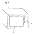
- Fig. 2 is a perspective view illustrating an exterior of the heating cooker including the steam generator 20 according to the first embodiment of the present invention.
- Fig. 3 is a schematic cross-sectional view showing configuration of the steam generator 20 according to the first embodiment of the present invention.
- a plurality of fins 22 are provided near a center of an inner wall of the water storage chamber 19.
- the fins 22 are arranged in 5mm horizontal intervals to cross the first steam generating heater 40 and the second steam generating heater 41 at right angles to the heaters.
- the fins 22 are integral with the water storage chamber 19, and each of the fins 22 has a thicknesses of about 2mm in the first embodiment.
- a longitudinal direction of the fins 22 is set to be substantially the same direction as a steam-generating direction. That is, the fins 22 are formed along the steam-generating direction.
- the "steam-generating direction” means a traveling direction of vapor, which was generated in the water, toward the water surface, or a traveling direction of vapor exited from the water surface.
- the steam generating direction is a direction perpendicular to the water surface in the water storage chamber 19 or a vertical direction in the water storage chamber 19.
- Thicknesses, lengths and intervals of the fins 22 may be set based on outputs or shapes of the first steam generating heater 40 and the second steam generating heater 41, for example.
- the bottom surface in the inner surface of the water storage chamber 19 is configured to have a sloping surface 24 with a sloping angle of about 5 degrees relative to the horizontal plane, whose center portion is located at the lowest end.
- the bottom surface of the water storage chamber 19 is formed in a so called funnel shape, and a discharge port 37 is provided at the lowest end, which is the center portion.
- a water supply port 36 which supplies water to the water storage chamber 19 is formed in the sloping surface 24 of the water storage chamber 19.
- the water supply port 36 is placed at left side of the discharge port 37 in Fig.3 .
- the water supply port 36 and the discharge port 37 are formed in the different position of the bottom surface of the water storage chamber 19.
- the sloping angle of the sloping surface 24 according to the first embodiment is set about 5 degrees relative to horizontal plane, the sloping angle can be determined according to the required water flow in the specification of the heating cooker because water flow is different according to a shape of the water discharge passage 30, amount of water flow supplied after water discharge or the like.
- a translucent water supply passage 27 formed with a silicone material, which is an elastic body, with an inner diameter of 6 mm is connected to an upstream side which is located below the water supply port 36.
- the other end of the water supply passage 27 is connected to the water supply tank 29 via a water supply pump 28, which is a water supply device.
- the water supply pump 28 is provided as the water supply device which supplies water into the water storage chamber via the water supply passage 27 and the water supply port 36 arranged in the water storage chamber 19.
- a water discharge passage 30 in which a first water discharge passage 25 and a second water discharge passage 35 are connected consecutively is provided in the downstream side, which means below the discharge port 37.
- the first water supply passage 25 is translucent and formed with a silicone material which is an elastic body, and has a pipe like shape with an inner diameter of 6mm.
- the first water discharge passage 25 is connected to the discharge port 37 without using another part such as a tube.
- the first water discharge passage 25 is extended downward (in approximately vertical direction) from the discharge port 37, and bent toward approximately horizontal direction at a predetermined length from the discharge port 37, then bent toward upward (in approximately vertical direction) at a further predetermined length.
- the first water discharge passage 25 has so called a U shape to be convex downward.
- the second water discharge passage 35 which is formed by bending a copper pipe with an inner diameter of 6mm, is connected to a downstream side of the first water discharge passage 25 without using another part such as a tube.
- the second water supply passage 35 is extended upward from the connecting portion with the first water discharge passage 25 and further extended beyond the horizontally same level of the first steam generating heater 40 and the second steam generating heater 41.
- the second water discharge passage 35 is bent with 180 degrees at a water discharge passage upmost point 32, as an apex of a U shape, which is located about at the same level as an upmost point of the top surface in the inner surface of the water storage chamber 19.
- the second water discharge passage 35 located at downstream side of the water discharge passage upmost point 32 extends vertically downward.
- the second water discharge passage 35 has so called an inverted U shape to be convex upward.
- the second water supply passage 35 as formed so far is configured to supply water which flows from the first water supply chamber 25 to a water discharge tank 31 through a water supply passage outlet 33.
- the water supply passage outlet 33 of the water supply passage 35 is provided at the position lower than the bottom surface of the water storage chamber 19.
- the second water discharge passage 35 is configured to use a copper pipe, it can also use a pipe made of a material such as aluminum, iron or the like.
- a water supply tank 29 is formed by two parts, a container portion and a lid portion, and each of them is formed with an AS resin material, which is a transparent amorphous plastic material.
- the container portion and the lid portion are hermetically connected by positioning a packing (not illustrated) between them to avoid water leakage.
- a water discharge line 26 and a full water line 38 are indicated by silkscreen on the side surface of the water supply tank 29.
- a volume of water in the water supply tank 29 becomes 100 ml, which is 10 ml more than an inner volume of the water storage chamber 19.
- a volume of water in the water supply tank 29 becomes 400 ml.
- the water storage chamber 19, the water supply tank 29 and the water discharge tank 31 illustrated in Fig.3 do not show actual relative volumes, and the volume of the water storage chamber 19 is exaggerated compared to those of the water supply tank 29 and the water discharge tank 31.
- the water discharge line 26 and the full water line 38 are indicated by silkscreen, it is not limited to the silkscreen.
- the lines can be indicated by stencil onto the water supply tank 29, or by making a concavo-convex portion on the water supply tank 29.
- Fig. 4 is a schematic transverse section view of the steam generator 20 according to the first embodiment of the present invention.
- the fins 22 extend from a first side surface 19A in the water storage chamber 19 and distal ends of the fins 22 are spaced from a second side surface 19B in the water storage chamber 19.
- the second side surface 19B is formed by the water storage chamber cover 34, being opposite to the first side surface.
- gaps between the distal ends of the fins 22 extending from the water storage chamber 19 and the water storage chamber cover 34 are 2mm.
- a cross-sectional area defined by the water storage chamber 19, the fins 22 and the water storage chamber cover 34 in a plane perpendicular to the steam-generating direction (the area corresponding to a white area in Fig. 4 outlined by the water storage chamber 19, the fins 22 and the water storage chamber cover 34) is set to be equal to or larger than a cross-sectional area of the steam spout port 21.
- the gaps between the distal ends of the fins 22 extending from the water storage chamber 19 and the water storage chamber cover 34 are 2mm.
- the gaps may be changed to be larger or smaller than 2mm as long as there is a space between the fins 22 and the water storage chamber cover 34, where water can enter.
- the magnetron 6 emits microwaves.
- the microwaves emitted from the magnetron 6 are propagated through the waveguide 14 and directed to the rotational antenna 11.
- microwaves are supplied to the inside of the heating chamber 1 while being stirred by the rotational antenna 11 which is being rotated by the motor 18.
- Some of the microwaves supplied in the heating chamber 1 are directly absorbed by the food 5 which is an object to be heated, and some of them are absorbed by the food 5 after reflected by the wall surface of the heating chamber 1, thereby heating the food 5.
- a heating chamber heater 2 or a convection heater 8 is energized, and thus caused to generate heat for heating air, and heated air is circulated in the heating chamber 1 by the circulation fan 7, and thereby heating the food 5.
- the infrared sensor 15 and the inside thermistor 9 detect condition of the food and condition inside the heating chamber 1, respectively, and switching between the heating chamber heater 2 and the convection heater 8 or output control are conducted accordingly.
- microwaves are supplied to the heating chamber 1 as well as the microwave mode, and the supplied microwaves cause the heating element located at the rear side of the mounting plate 4 to generate heat. Temperature of the entire mounting plate 4 becomes high by the heat transferred from the heating element by heat conduction, and thereby heating the food 5 from the lower side.
- the microwaves flow through the space between the mounting plate 4 and the wall surface of the heating chamber 1, and thereby heating the food 5.
- the heating chamber heater 2 is energized and thus caused to generate heat, and the food 5 is heated from upper side by radiation heat from the heating chamber heater 2.
- the grill mode it is automatically selected according to the item selected by a user whether applying radiation heat by the heating chamber heater 2 together with heat by microwaves at the same time, or selectively applying heat by microwaves or applying radiation heat by the heating chamber heater 2 independently.
- the infrared sensor 15 and the inside thermistor 9 detect condition of the food and condition inside the heating chamber 1, respectively, and switching between heating by microwaves and the heating chamber heater 2 or output control are conducted accordingly.
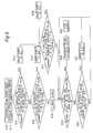
- Fig. 5 shows a flow chart of a steam heating mode of the steam generator 20 of the first embodiment of the present invention.
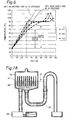
- Fig. 6 is a graph showing a relationship between time and temperature of the water storage chamber thermistor provided in the steam generator 20 according to the first embodiment of the present invention.
- step S12 when the temperature of the water storage chamber 19 detected by the water storage chamber thermistor 42 is increased by more than 60°C in 30 seconds from the start (step S12), the control portion 10 issues a water supply instruction to the water supply pump 28 for performing a water supply of about 40ml (step S13).
- the water supply by the water supply pump 28 is to supply the water in the water supply tank 29 to the water storage chamber 19 from the water supply pump 28 via the water supply passage 27 and the water supply port 36.
- the operation of the water supply pump 28 is stopped.
- step S14 when the temperature increasing value of the water storage chamber 19 in 30 seconds exceeds 50°C and equal to or less than 60°C (step S14), the control portion 10 issues a water supply instruction to the water supply pump 28 for performing a water supply of about 20ml (step S15).
- step S16 when the temperature increasing value of the water storage chamber 19 is less than 50°C, it is determined that the water storage chamber 19 storages a sufficient amount of the water. This will not trigger water supply (step S16).
- the control portion 10 issues a water supply instruction to the water supply pump 28 for performing a water supply of about 10ml (step S18). Until the temperature increasing value of the water chamber 19 in 5 seconds after the water supply becomes less than 7°C, the water supply (S18) will be repeated.
- Such a water supply to the water storage chamber 19 increases the water level to below the second steam generating heater 41 and the water is filled to contact the fins 22. Heating in this state using the first steam generating heater 40 and the second steam generating heater 41 can heat the water in the water storage chamber 19 either directly or via the fins 22, thereby evaporating the heated water to become steam.
- the steam generated in the water chamber 19 passes through the steam conduit passage 23 to be discharged from the steam spout port 21 into the heating chamber 1.
- the steam discharged into the heating chamber 1 heats the food 5.
- the water storage chamber 19 and the water discharge passage 30 are communicated with each other, and therefore increasing of the water level in the water storage chamber 19 will increase the water level in the water discharge passage 30 at the same time.
- a water supply amount by the water supply pump 28 is adjusted so that the water level in the water storage chamber 19 does not exceed the second steam generating heater 41.
- the water in the water storage chamber 19 is evaporated in a state of stored in the water storage chamber 19, not immediately after supplied with its small amount into the water storage chamber. This makes the water in the water storage chamber 19 to be likely to remain in the water storage chamber 19, thereby suppressing scale deposition.
- a highly-reliable steam generator 20 can be provided.
- the first steam generating heater 40 and the second steam generating heater 41 are disposed in a vicinity of the water surface (normal water level). This can evaporate only the water near the water surface prior to heating the water on a lower side in water chamber 19, thereby rapidly generating the steam. That is, the steam generator 20 operable to quickly generate the steam at an early stage can be provided. Further, placing the first steam generating heater 40 and the second steam generating heater 41 to cross the plurality of the fins 22 can heat the water via the fins 22, thereby achieving a uniform water heating.
- the first steam generating heater 40 is arranged below the water surface while the second steam generating heater 41 is arranged above the water surface. According to such an arrangement, the first steam generating heater 40 on the lower side mainly heats the water to generate the steam, while the second steam generating heater 41 on the upper side mainly heats the generated steam or boiling water. Heating the boiling water by the second steam generating heater 41 can change the boiling water into steam, thereby preventing running-up by the boiling water.
- an output of the first steam generating heater 40 for mainly heating the water is set to be larger than an output of the second steam generating heater 41 for mainly heating the steam or the boiling water. Such a setting of the outputs according to the desired heating amounts leads to efficient generation of the steam.
- first steam generating heater 40 and the second steam generating heater 41 are energized at the same time, but either one of the heaters may be energized alone depending on a selected cooking menu or output.
- Performing the water supply by the water supply pump 28 in S21 will decrease the temperature of the water storage chamber 19.
- Water evaporation will continue after performing the water supply once, while a following water supply will not be performed until the water level is decreased and the temperature is increased.
- Such control can maintain the water level in the water storage chamber 19 at or above a certain level. That is, it is possible to detect the water level and perform the water supply in a simple manner without using a water level sensor.
- Thresholds for temperature increasing of the water storage chamber 19 or timings of performing the water supply used in the flow shown in Fig. 5 may be set based on amount of the water supply because the amount will change according to the outputs of the first steam generating heater 40 and the second steam generating heater 41 or the shape of the water storage chamber 19.
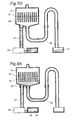
- Fig. 7A is a cross-sectional view showing a first operation of the steam generator 20 according to the first embodiment of the present invention performing a water discharge process using the siphon principle.
- Fig. 7B is a cross-sectional view showing a second operation of the steam generator 20 according to the first embodiment of the present invention performing the water discharge process using the siphon principle.
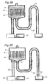
- Fig. 7C is a cross-sectional view showing a third operation of the steam generator 20 according to the first embodiment of the present invention performing the water discharge process using the siphon principle.
- Fig. 7D is a cross-sectional view showing a forth operation of the steam generator 20 according to the first embodiment of the present invention performing the water discharge process using the siphon principle.
- water is supplied to the water storage chamber 19 by automatically driving the water supply pump 28 until the water level in the water storage chamber 19 reaches the water discharge passage upmost point 32 which is located upper than the water level in the water storage chamber 19 during the normal heating condition. If the water level is raised to the water discharge passage upmost point 32, vertical difference "a" is created between the water level in the water storage chamber 19 and the water level in the water discharge passage 30. As illustrated in Fig.
- operation period for the water supply pump 28 is set such that water supply rate is a little bit more than the water supply rate required for discharging water from the water storage chamber 19 considering variation in the operation of the water supply pump 28. Therefore, a means for detecting the water level in the water storage chamber 19 during discharging water can be omitted in the steam generator 20 according to the first embodiment.
- the water discharge by the siphon principle is performed by operating the water supply pump 28 to increase the water level to the water discharge passage upmost point 32, with the water supply tank 29 having a predetermined amount of water. Even while the water discharge by the siphon principle is being performed, the water supply pump 28 is operated to continue the water supply. According to such control, even when the water in the water tank 29 is empty, the water supply pump 28 feeds the air instead of water into the water supply passage 27, thereby pushing the residual water out of the water supply passage 27 to be discharged. The discharged water joins the water which has been discharged by the siphon principle, and both will be discharged simultaneously.
- the large bubbles are less likely to be generated, thereby reducing a burst sound of the bubbles. Also, the temperature of the contact portion between the water storage chamber 19 and the water can be decreased, thereby suppressing scale deposition, which is likely to occur at higher temperature.
- the temperature increasing value of the water storage chamber 19 in 30 seconds exceeds 50°C, it is estimated that the water level in the water storage chamber 19 is low, and a predetermined amount of water supply is performed accordingly. Thus, the temperature of the water storage chamber 19 is decreased, and heating of the empty water storage chamber 19 can be prevented. Therefore, failure of the first steam generating heater 40 and the second steam generating heater 41 due to excessive heating, or efficiency reduction of steam generating can be prevented. That is, the steam generator 20 with high reliability and safety can be provided.
- the configuration such that at least an inner surface of the first water discharge passage 25 of the water discharge passage 30 is coated with a nonmetallic material to form the nonmetallic coating layer it can prevent scales from being adhered to the first water discharge passage 25 with a simple configuration, for example, even if a metallic material has to be applied to the first water discharge passage 25 with reasons of heat resistance or the like. Needless to say, if the above-mentioned coating layer is formed on an inner surface of the water discharge passage 25 formed by using a nonmetallic material, it can enhance heat resistance performance and reliability.
Landscapes
- Engineering & Computer Science (AREA)
- General Engineering & Computer Science (AREA)
- Mechanical Engineering (AREA)
- Physics & Mathematics (AREA)
- Sustainable Energy (AREA)
- Thermal Sciences (AREA)
- Life Sciences & Earth Sciences (AREA)
- Sustainable Development (AREA)
- Food Science & Technology (AREA)
- Chemical & Material Sciences (AREA)
- Combustion & Propulsion (AREA)
- Electromagnetism (AREA)
- Electric Ovens (AREA)
- Cookers (AREA)
Applications Claiming Priority (2)
| Application Number | Priority Date | Filing Date | Title |
|---|---|---|---|
| JP2012161172 | 2012-07-20 | ||
| PCT/JP2013/004270 WO2014013700A1 (fr) | 2012-07-20 | 2013-07-10 | Dispositif de génération de vapeur et dispositif de cuisson avec dispositif de génération de vapeur |
Publications (3)
| Publication Number | Publication Date |
|---|---|
| EP2876367A1 true EP2876367A1 (fr) | 2015-05-27 |
| EP2876367A4 EP2876367A4 (fr) | 2015-08-19 |
| EP2876367B1 EP2876367B1 (fr) | 2017-08-30 |
Family
ID=49948543
Family Applications (1)
| Application Number | Title | Priority Date | Filing Date |
|---|---|---|---|
| EP13820682.6A Active EP2876367B1 (fr) | 2012-07-20 | 2013-07-10 | Dispositif de génération de vapeur et dispositif de cuisson avec dispositif de génération de vapeur |
Country Status (5)
| Country | Link |
|---|---|
| US (1) | US9615688B2 (fr) |
| EP (1) | EP2876367B1 (fr) |
| JP (1) | JP6029032B2 (fr) |
| CN (1) | CN104471315B (fr) |
| WO (1) | WO2014013700A1 (fr) |
Families Citing this family (14)
| Publication number | Priority date | Publication date | Assignee | Title |
|---|---|---|---|---|
| CN103892697B (zh) * | 2014-03-28 | 2016-08-17 | 广东美的厨房电器制造有限公司 | 控制方法、控制装置和蒸汽烹饪器具 |
| CN104367181B (zh) * | 2014-11-13 | 2016-08-17 | 绵阳市树人机电制造有限责任公司 | 一种节能蒸汽式稀饭器 |
| US20160341444A1 (en) * | 2015-05-21 | 2016-11-24 | Darcy McMenamin | Grill grate heat exchanger |
| EP4137015A1 (fr) * | 2017-07-12 | 2023-02-22 | Home Tech Innovation, Inc. | Système de stockage et de cuisson d'aliments |
| CA3065773C (fr) | 2017-08-09 | 2021-02-09 | Sharkninja Operating Llc | Dispositif de cuisson et composants de celui-ci |
| AU2018333946B2 (en) | 2017-09-15 | 2024-05-30 | Home Tech Innovation, Inc. | Apparatus and methods for at least semi-autonomous meal storage and cooking |
| CN108131654B (zh) * | 2017-12-25 | 2019-07-30 | 安徽工业大学 | 一种焦炭反应性测定装置的水蒸气发生方法 |
| WO2020010513A1 (fr) * | 2018-07-10 | 2020-01-16 | Jung Gmbh Apparatebau | Appareil de cuisson pour produits de boulangerie comprenant un générateur de vapeur |
| EP4714316A2 (fr) | 2019-02-25 | 2026-03-25 | SharkNinja Operating LLC | Système de cuisson avec protection |
| US11051654B2 (en) | 2019-02-25 | 2021-07-06 | Sharkninja Operating Llc | Cooking device and components thereof |
| CN110236376B (zh) * | 2019-07-05 | 2024-06-14 | 华帝股份有限公司 | 一种蒸汽发生装置及应用其的蒸汽烹饪设备 |
| JPWO2021153611A1 (fr) * | 2020-01-30 | 2021-08-05 | ||
| US11134808B2 (en) | 2020-03-30 | 2021-10-05 | Sharkninja Operating Llc | Cooking device and components thereof |
| CN118998733B (zh) * | 2024-08-05 | 2025-11-25 | 中国船舶集团有限公司第七一九研究所 | 低振动噪声换热装置 |
Family Cites Families (15)
| Publication number | Priority date | Publication date | Assignee | Title |
|---|---|---|---|---|
| JPS5561201U (fr) * | 1978-10-20 | 1980-04-25 | ||
| JPS56130505A (en) * | 1980-03-14 | 1981-10-13 | Motoyasu Nakanishi | Boiler device |
| JP3607927B2 (ja) * | 2000-03-15 | 2005-01-05 | 三洋電機株式会社 | 蒸気発生装置 |
| ITUD20030130A1 (it) * | 2003-06-12 | 2004-12-13 | De Longhi Spa | Apparecchiatura per generare vapore utilizzabile in un elettrodomestico. |
| JP2006038315A (ja) * | 2004-07-26 | 2006-02-09 | Toshiba Corp | 加熱調理器 |
| JP2006284131A (ja) | 2005-04-04 | 2006-10-19 | Matsushita Electric Ind Co Ltd | 加熱調理器 |
| FR2884688B1 (fr) * | 2005-04-22 | 2007-06-29 | Premark Feg Llc | Four professionnel grande cuisine a energie hyperfrequences confinee dans la cavite de cuisson |
| JP2008032304A (ja) | 2006-07-28 | 2008-02-14 | Sanyo Electric Co Ltd | 加熱調理器及び加熱調理器用の蒸気発生装置 |
| JP5052988B2 (ja) | 2007-08-08 | 2012-10-17 | シャープ株式会社 | 蒸気調理器 |
| KR101232488B1 (ko) | 2007-08-08 | 2013-02-12 | 샤프 가부시키가이샤 | 증기 조리기 |
| JP4267679B2 (ja) | 2008-03-26 | 2009-05-27 | 株式会社東芝 | 加熱調理器 |
| JP4435246B2 (ja) * | 2008-06-26 | 2010-03-17 | シャープ株式会社 | 蒸気発生装置及び加熱調理器 |
| JP2010054176A (ja) | 2008-08-29 | 2010-03-11 | Sharp Corp | 加熱調理器 |
| CN102834671B (zh) | 2010-04-28 | 2015-05-20 | 夏普株式会社 | 加热烹调器 |
| GB201017461D0 (en) * | 2010-10-15 | 2010-12-01 | Strix Ltd | Electric steam generation |
-
2013
- 2013-07-10 EP EP13820682.6A patent/EP2876367B1/fr active Active
- 2013-07-10 JP JP2014525709A patent/JP6029032B2/ja active Active
- 2013-07-10 WO PCT/JP2013/004270 patent/WO2014013700A1/fr not_active Ceased
- 2013-07-10 CN CN201380037233.2A patent/CN104471315B/zh active Active
- 2013-07-10 US US14/415,487 patent/US9615688B2/en active Active
Also Published As
| Publication number | Publication date |
|---|---|
| WO2014013700A1 (fr) | 2014-01-23 |
| US20150173552A1 (en) | 2015-06-25 |
| EP2876367B1 (fr) | 2017-08-30 |
| EP2876367A4 (fr) | 2015-08-19 |
| JPWO2014013700A1 (ja) | 2016-06-30 |
| JP6029032B2 (ja) | 2016-11-24 |
| US9615688B2 (en) | 2017-04-11 |
| CN104471315A (zh) | 2015-03-25 |
| CN104471315B (zh) | 2016-10-05 |
Similar Documents
| Publication | Publication Date | Title |
|---|---|---|
| EP2876367B1 (fr) | Dispositif de génération de vapeur et dispositif de cuisson avec dispositif de génération de vapeur | |
| EP2975320B1 (fr) | Dispositif de génération de vapeur | |
| US9841182B2 (en) | Steam generator and heating cooker comprising steam generator | |
| US10125978B2 (en) | Steam generator | |
| US10835072B2 (en) | Steam generator | |
| US9890946B2 (en) | Steam generator | |
| JP2014020705A (ja) | 蒸気発生装置 |
Legal Events
| Date | Code | Title | Description |
|---|---|---|---|
| PUAI | Public reference made under article 153(3) epc to a published international application that has entered the european phase |
Free format text: ORIGINAL CODE: 0009012 |
|
| 17P | Request for examination filed |
Effective date: 20150119 |
|
| AK | Designated contracting states |
Kind code of ref document: A1 Designated state(s): AL AT BE BG CH CY CZ DE DK EE ES FI FR GB GR HR HU IE IS IT LI LT LU LV MC MK MT NL NO PL PT RO RS SE SI SK SM TR |
|
| AX | Request for extension of the european patent |
Extension state: BA ME |
|
| RA4 | Supplementary search report drawn up and despatched (corrected) |
Effective date: 20150720 |
|
| RIC1 | Information provided on ipc code assigned before grant |
Ipc: F24C 15/32 20060101ALI20150714BHEP Ipc: F24C 1/00 20060101ALI20150714BHEP Ipc: H05B 6/80 20060101ALI20150714BHEP Ipc: F22B 1/28 20060101AFI20150714BHEP Ipc: A47J 27/04 20060101ALI20150714BHEP Ipc: A47J 36/02 20060101ALI20150714BHEP |
|
| DAX | Request for extension of the european patent (deleted) | ||
| GRAP | Despatch of communication of intention to grant a patent |
Free format text: ORIGINAL CODE: EPIDOSNIGR1 |
|
| INTG | Intention to grant announced |
Effective date: 20170227 |
|
| GRAS | Grant fee paid |
Free format text: ORIGINAL CODE: EPIDOSNIGR3 |
|
| GRAA | (expected) grant |
Free format text: ORIGINAL CODE: 0009210 |
|
| AK | Designated contracting states |
Kind code of ref document: B1 Designated state(s): AL AT BE BG CH CY CZ DE DK EE ES FI FR GB GR HR HU IE IS IT LI LT LU LV MC MK MT NL NO PL PT RO RS SE SI SK SM TR |
|
| REG | Reference to a national code |
Ref country code: GB Ref legal event code: FG4D |
|
| REG | Reference to a national code |
Ref country code: CH Ref legal event code: EP |
|
| REG | Reference to a national code |
Ref country code: AT Ref legal event code: REF Ref document number: 923908 Country of ref document: AT Kind code of ref document: T Effective date: 20170915 |
|
| REG | Reference to a national code |
Ref country code: IE Ref legal event code: FG4D |
|
| REG | Reference to a national code |
Ref country code: DE Ref legal event code: R096 Ref document number: 602013025927 Country of ref document: DE |
|
| REG | Reference to a national code |
Ref country code: NL Ref legal event code: MP Effective date: 20170830 |
|
| REG | Reference to a national code |
Ref country code: LT Ref legal event code: MG4D |
|
| REG | Reference to a national code |
Ref country code: AT Ref legal event code: MK05 Ref document number: 923908 Country of ref document: AT Kind code of ref document: T Effective date: 20170830 |
|
| PG25 | Lapsed in a contracting state [announced via postgrant information from national office to epo] |
Ref country code: FI Free format text: LAPSE BECAUSE OF FAILURE TO SUBMIT A TRANSLATION OF THE DESCRIPTION OR TO PAY THE FEE WITHIN THE PRESCRIBED TIME-LIMIT Effective date: 20170830 Ref country code: NO Free format text: LAPSE BECAUSE OF FAILURE TO SUBMIT A TRANSLATION OF THE DESCRIPTION OR TO PAY THE FEE WITHIN THE PRESCRIBED TIME-LIMIT Effective date: 20171130 Ref country code: HR Free format text: LAPSE BECAUSE OF FAILURE TO SUBMIT A TRANSLATION OF THE DESCRIPTION OR TO PAY THE FEE WITHIN THE PRESCRIBED TIME-LIMIT Effective date: 20170830 Ref country code: LT Free format text: LAPSE BECAUSE OF FAILURE TO SUBMIT A TRANSLATION OF THE DESCRIPTION OR TO PAY THE FEE WITHIN THE PRESCRIBED TIME-LIMIT Effective date: 20170830 Ref country code: SE Free format text: LAPSE BECAUSE OF FAILURE TO SUBMIT A TRANSLATION OF THE DESCRIPTION OR TO PAY THE FEE WITHIN THE PRESCRIBED TIME-LIMIT Effective date: 20170830 Ref country code: AT Free format text: LAPSE BECAUSE OF FAILURE TO SUBMIT A TRANSLATION OF THE DESCRIPTION OR TO PAY THE FEE WITHIN THE PRESCRIBED TIME-LIMIT Effective date: 20170830 |
|
| PG25 | Lapsed in a contracting state [announced via postgrant information from national office to epo] |
Ref country code: BG Free format text: LAPSE BECAUSE OF FAILURE TO SUBMIT A TRANSLATION OF THE DESCRIPTION OR TO PAY THE FEE WITHIN THE PRESCRIBED TIME-LIMIT Effective date: 20171130 Ref country code: IS Free format text: LAPSE BECAUSE OF FAILURE TO SUBMIT A TRANSLATION OF THE DESCRIPTION OR TO PAY THE FEE WITHIN THE PRESCRIBED TIME-LIMIT Effective date: 20171230 Ref country code: GR Free format text: LAPSE BECAUSE OF FAILURE TO SUBMIT A TRANSLATION OF THE DESCRIPTION OR TO PAY THE FEE WITHIN THE PRESCRIBED TIME-LIMIT Effective date: 20171201 Ref country code: ES Free format text: LAPSE BECAUSE OF FAILURE TO SUBMIT A TRANSLATION OF THE DESCRIPTION OR TO PAY THE FEE WITHIN THE PRESCRIBED TIME-LIMIT Effective date: 20170830 Ref country code: RS Free format text: LAPSE BECAUSE OF FAILURE TO SUBMIT A TRANSLATION OF THE DESCRIPTION OR TO PAY THE FEE WITHIN THE PRESCRIBED TIME-LIMIT Effective date: 20170830 Ref country code: LV Free format text: LAPSE BECAUSE OF FAILURE TO SUBMIT A TRANSLATION OF THE DESCRIPTION OR TO PAY THE FEE WITHIN THE PRESCRIBED TIME-LIMIT Effective date: 20170830 |
|
| PG25 | Lapsed in a contracting state [announced via postgrant information from national office to epo] |
Ref country code: NL Free format text: LAPSE BECAUSE OF FAILURE TO SUBMIT A TRANSLATION OF THE DESCRIPTION OR TO PAY THE FEE WITHIN THE PRESCRIBED TIME-LIMIT Effective date: 20170830 |
|
| PG25 | Lapsed in a contracting state [announced via postgrant information from national office to epo] |
Ref country code: CZ Free format text: LAPSE BECAUSE OF FAILURE TO SUBMIT A TRANSLATION OF THE DESCRIPTION OR TO PAY THE FEE WITHIN THE PRESCRIBED TIME-LIMIT Effective date: 20170830 Ref country code: PL Free format text: LAPSE BECAUSE OF FAILURE TO SUBMIT A TRANSLATION OF THE DESCRIPTION OR TO PAY THE FEE WITHIN THE PRESCRIBED TIME-LIMIT Effective date: 20170830 Ref country code: DK Free format text: LAPSE BECAUSE OF FAILURE TO SUBMIT A TRANSLATION OF THE DESCRIPTION OR TO PAY THE FEE WITHIN THE PRESCRIBED TIME-LIMIT Effective date: 20170830 Ref country code: RO Free format text: LAPSE BECAUSE OF FAILURE TO SUBMIT A TRANSLATION OF THE DESCRIPTION OR TO PAY THE FEE WITHIN THE PRESCRIBED TIME-LIMIT Effective date: 20170830 |
|
| PG25 | Lapsed in a contracting state [announced via postgrant information from national office to epo] |
Ref country code: IT Free format text: LAPSE BECAUSE OF FAILURE TO SUBMIT A TRANSLATION OF THE DESCRIPTION OR TO PAY THE FEE WITHIN THE PRESCRIBED TIME-LIMIT Effective date: 20170830 Ref country code: EE Free format text: LAPSE BECAUSE OF FAILURE TO SUBMIT A TRANSLATION OF THE DESCRIPTION OR TO PAY THE FEE WITHIN THE PRESCRIBED TIME-LIMIT Effective date: 20170830 Ref country code: SK Free format text: LAPSE BECAUSE OF FAILURE TO SUBMIT A TRANSLATION OF THE DESCRIPTION OR TO PAY THE FEE WITHIN THE PRESCRIBED TIME-LIMIT Effective date: 20170830 Ref country code: SM Free format text: LAPSE BECAUSE OF FAILURE TO SUBMIT A TRANSLATION OF THE DESCRIPTION OR TO PAY THE FEE WITHIN THE PRESCRIBED TIME-LIMIT Effective date: 20170830 |
|
| REG | Reference to a national code |
Ref country code: DE Ref legal event code: R097 Ref document number: 602013025927 Country of ref document: DE |
|
| PLBE | No opposition filed within time limit |
Free format text: ORIGINAL CODE: 0009261 |
|
| STAA | Information on the status of an ep patent application or granted ep patent |
Free format text: STATUS: NO OPPOSITION FILED WITHIN TIME LIMIT |
|
| 26N | No opposition filed |
Effective date: 20180531 |
|
| PG25 | Lapsed in a contracting state [announced via postgrant information from national office to epo] |
Ref country code: SI Free format text: LAPSE BECAUSE OF FAILURE TO SUBMIT A TRANSLATION OF THE DESCRIPTION OR TO PAY THE FEE WITHIN THE PRESCRIBED TIME-LIMIT Effective date: 20170830 |
|
| REG | Reference to a national code |
Ref country code: CH Ref legal event code: PL |
|
| GBPC | Gb: european patent ceased through non-payment of renewal fee |
Effective date: 20180710 |
|
| PG25 | Lapsed in a contracting state [announced via postgrant information from national office to epo] |
Ref country code: MC Free format text: LAPSE BECAUSE OF FAILURE TO SUBMIT A TRANSLATION OF THE DESCRIPTION OR TO PAY THE FEE WITHIN THE PRESCRIBED TIME-LIMIT Effective date: 20170830 Ref country code: LU Free format text: LAPSE BECAUSE OF NON-PAYMENT OF DUE FEES Effective date: 20180710 |
|
| REG | Reference to a national code |
Ref country code: BE Ref legal event code: MM Effective date: 20180731 |
|
| REG | Reference to a national code |
Ref country code: IE Ref legal event code: MM4A |
|
| PG25 | Lapsed in a contracting state [announced via postgrant information from national office to epo] |
Ref country code: LI Free format text: LAPSE BECAUSE OF NON-PAYMENT OF DUE FEES Effective date: 20180731 Ref country code: IE Free format text: LAPSE BECAUSE OF NON-PAYMENT OF DUE FEES Effective date: 20180710 Ref country code: GB Free format text: LAPSE BECAUSE OF NON-PAYMENT OF DUE FEES Effective date: 20180710 Ref country code: FR Free format text: LAPSE BECAUSE OF NON-PAYMENT OF DUE FEES Effective date: 20180731 Ref country code: CH Free format text: LAPSE BECAUSE OF NON-PAYMENT OF DUE FEES Effective date: 20180731 |
|
| PG25 | Lapsed in a contracting state [announced via postgrant information from national office to epo] |
Ref country code: BE Free format text: LAPSE BECAUSE OF NON-PAYMENT OF DUE FEES Effective date: 20180731 |
|
| PG25 | Lapsed in a contracting state [announced via postgrant information from national office to epo] |
Ref country code: MT Free format text: LAPSE BECAUSE OF NON-PAYMENT OF DUE FEES Effective date: 20180710 |
|
| PG25 | Lapsed in a contracting state [announced via postgrant information from national office to epo] |
Ref country code: TR Free format text: LAPSE BECAUSE OF FAILURE TO SUBMIT A TRANSLATION OF THE DESCRIPTION OR TO PAY THE FEE WITHIN THE PRESCRIBED TIME-LIMIT Effective date: 20170830 |
|
| PG25 | Lapsed in a contracting state [announced via postgrant information from national office to epo] |
Ref country code: PT Free format text: LAPSE BECAUSE OF FAILURE TO SUBMIT A TRANSLATION OF THE DESCRIPTION OR TO PAY THE FEE WITHIN THE PRESCRIBED TIME-LIMIT Effective date: 20170830 Ref country code: HU Free format text: LAPSE BECAUSE OF FAILURE TO SUBMIT A TRANSLATION OF THE DESCRIPTION OR TO PAY THE FEE WITHIN THE PRESCRIBED TIME-LIMIT; INVALID AB INITIO Effective date: 20130710 |
|
| PG25 | Lapsed in a contracting state [announced via postgrant information from national office to epo] |
Ref country code: MK Free format text: LAPSE BECAUSE OF NON-PAYMENT OF DUE FEES Effective date: 20170830 Ref country code: CY Free format text: LAPSE BECAUSE OF FAILURE TO SUBMIT A TRANSLATION OF THE DESCRIPTION OR TO PAY THE FEE WITHIN THE PRESCRIBED TIME-LIMIT Effective date: 20170830 |
|
| PG25 | Lapsed in a contracting state [announced via postgrant information from national office to epo] |
Ref country code: AL Free format text: LAPSE BECAUSE OF FAILURE TO SUBMIT A TRANSLATION OF THE DESCRIPTION OR TO PAY THE FEE WITHIN THE PRESCRIBED TIME-LIMIT Effective date: 20170830 |
|
| PGFP | Annual fee paid to national office [announced via postgrant information from national office to epo] |
Ref country code: DE Payment date: 20250722 Year of fee payment: 13 |