EP2876389A1 - Récipient à isolation thermique - Google Patents
Récipient à isolation thermique Download PDFInfo
- Publication number
- EP2876389A1 EP2876389A1 EP14004268.0A EP14004268A EP2876389A1 EP 2876389 A1 EP2876389 A1 EP 2876389A1 EP 14004268 A EP14004268 A EP 14004268A EP 2876389 A1 EP2876389 A1 EP 2876389A1
- Authority
- EP
- European Patent Office
- Prior art keywords
- container
- wall
- elements
- vacuum insulation
- container according
- Prior art date
- Legal status (The legal status is an assumption and is not a legal conclusion. Google has not performed a legal analysis and makes no representation as to the accuracy of the status listed.)
- Granted
Links
Images




Classifications
-
- F—MECHANICAL ENGINEERING; LIGHTING; HEATING; WEAPONS; BLASTING
- F25—REFRIGERATION OR COOLING; COMBINED HEATING AND REFRIGERATION SYSTEMS; HEAT PUMP SYSTEMS; MANUFACTURE OR STORAGE OF ICE; LIQUEFACTION SOLIDIFICATION OF GASES
- F25D—REFRIGERATORS; COLD ROOMS; ICE-BOXES; COOLING OR FREEZING APPARATUS NOT OTHERWISE PROVIDED FOR
- F25D3/00—Devices using other cold materials; Devices using cold-storage bodies
- F25D3/02—Devices using other cold materials; Devices using cold-storage bodies using ice, e.g. ice-boxes
- F25D3/06—Movable containers
-
- F—MECHANICAL ENGINEERING; LIGHTING; HEATING; WEAPONS; BLASTING
- F25—REFRIGERATION OR COOLING; COMBINED HEATING AND REFRIGERATION SYSTEMS; HEAT PUMP SYSTEMS; MANUFACTURE OR STORAGE OF ICE; LIQUEFACTION SOLIDIFICATION OF GASES
- F25D—REFRIGERATORS; COLD ROOMS; ICE-BOXES; COOLING OR FREEZING APPARATUS NOT OTHERWISE PROVIDED FOR
- F25D23/00—General constructional features
- F25D23/06—Walls
- F25D23/062—Walls defining a cabinet
- F25D23/063—Walls defining a cabinet formed by an assembly of panels
-
- F—MECHANICAL ENGINEERING; LIGHTING; HEATING; WEAPONS; BLASTING
- F25—REFRIGERATION OR COOLING; COMBINED HEATING AND REFRIGERATION SYSTEMS; HEAT PUMP SYSTEMS; MANUFACTURE OR STORAGE OF ICE; LIQUEFACTION SOLIDIFICATION OF GASES
- F25D—REFRIGERATORS; COLD ROOMS; ICE-BOXES; COOLING OR FREEZING APPARATUS NOT OTHERWISE PROVIDED FOR
- F25D2201/00—Insulation
- F25D2201/10—Insulation with respect to heat
- F25D2201/14—Insulation with respect to heat using subatmospheric pressure
-
- F—MECHANICAL ENGINEERING; LIGHTING; HEATING; WEAPONS; BLASTING
- F25—REFRIGERATION OR COOLING; COMBINED HEATING AND REFRIGERATION SYSTEMS; HEAT PUMP SYSTEMS; MANUFACTURE OR STORAGE OF ICE; LIQUEFACTION SOLIDIFICATION OF GASES
- F25D—REFRIGERATORS; COLD ROOMS; ICE-BOXES; COOLING OR FREEZING APPARATUS NOT OTHERWISE PROVIDED FOR
- F25D2303/00—Details of devices using other cold materials; Details of devices using cold-storage bodies
- F25D2303/08—Devices using cold storage material, i.e. ice or other freezable liquid
- F25D2303/082—Devices using cold storage material, i.e. ice or other freezable liquid disposed in a cold storage element not forming part of a container for products to be cooled, e.g. ice pack or gel accumulator
- F25D2303/0822—Details of the element
- F25D2303/08221—Fasteners or fixing means for the element
-
- F—MECHANICAL ENGINEERING; LIGHTING; HEATING; WEAPONS; BLASTING
- F25—REFRIGERATION OR COOLING; COMBINED HEATING AND REFRIGERATION SYSTEMS; HEAT PUMP SYSTEMS; MANUFACTURE OR STORAGE OF ICE; LIQUEFACTION SOLIDIFICATION OF GASES
- F25D—REFRIGERATORS; COLD ROOMS; ICE-BOXES; COOLING OR FREEZING APPARATUS NOT OTHERWISE PROVIDED FOR
- F25D2303/00—Details of devices using other cold materials; Details of devices using cold-storage bodies
- F25D2303/08—Devices using cold storage material, i.e. ice or other freezable liquid
- F25D2303/084—Position of the cold storage material in relationship to a product to be cooled
- F25D2303/0843—Position of the cold storage material in relationship to a product to be cooled on the side of the product
-
- F—MECHANICAL ENGINEERING; LIGHTING; HEATING; WEAPONS; BLASTING
- F25—REFRIGERATION OR COOLING; COMBINED HEATING AND REFRIGERATION SYSTEMS; HEAT PUMP SYSTEMS; MANUFACTURE OR STORAGE OF ICE; LIQUEFACTION SOLIDIFICATION OF GASES
- F25D—REFRIGERATORS; COLD ROOMS; ICE-BOXES; COOLING OR FREEZING APPARATUS NOT OTHERWISE PROVIDED FOR
- F25D2303/00—Details of devices using other cold materials; Details of devices using cold-storage bodies
- F25D2303/08—Devices using cold storage material, i.e. ice or other freezable liquid
- F25D2303/085—Compositions of cold storage materials
-
- F—MECHANICAL ENGINEERING; LIGHTING; HEATING; WEAPONS; BLASTING
- F25—REFRIGERATION OR COOLING; COMBINED HEATING AND REFRIGERATION SYSTEMS; HEAT PUMP SYSTEMS; MANUFACTURE OR STORAGE OF ICE; LIQUEFACTION SOLIDIFICATION OF GASES
- F25D—REFRIGERATORS; COLD ROOMS; ICE-BOXES; COOLING OR FREEZING APPARATUS NOT OTHERWISE PROVIDED FOR
- F25D2331/00—Details or arrangements of other cooling or freezing apparatus not provided for in other groups of this subclass
- F25D2331/80—Type of cooled receptacles
- F25D2331/804—Boxes
-
- F—MECHANICAL ENGINEERING; LIGHTING; HEATING; WEAPONS; BLASTING
- F25—REFRIGERATION OR COOLING; COMBINED HEATING AND REFRIGERATION SYSTEMS; HEAT PUMP SYSTEMS; MANUFACTURE OR STORAGE OF ICE; LIQUEFACTION SOLIDIFICATION OF GASES
- F25D—REFRIGERATORS; COLD ROOMS; ICE-BOXES; COOLING OR FREEZING APPARATUS NOT OTHERWISE PROVIDED FOR
- F25D2400/00—General features of, or devices for refrigerators, cold rooms, ice-boxes, or for cooling or freezing apparatus not covered by any other subclass
- F25D2400/36—Visual displays
Definitions
- the invention relates to a thermally insulated container according to the preamble of claim 1.
- thermally insulated containers are used in particular, but not exclusively, for transportation purposes in order to convey temperature-sensitive goods, for example medicines, while maintaining close temperature tolerances.
- a container wall is provided in generic containers, which completely encloses an interior, in which the material to be transported is arranged. At least one closable opening is provided in the container wall in order to be able to introduce the item to be transported into the container.
- Vacuum insulation elements In order to keep the heat flow through the container wall as low as possible, vacuum insulation elements are used for insulation. Vacuum insulation elements have a very high heat transfer resistance at a relatively low layer thickness, so that given a given outer volume, a relatively large usable volume is given with sufficient heat insulation. Due to the vacuum insulation elements, the heat flow from the outside to the inside as well as from the inside to the outside is made more difficult, so that the goods to be transported are protected against excessive heat as well as against excessive cold.
- Thermally insulated containers are known from the prior art, in which active cooling systems are used for additional cooling. For example, it is known that the interior of the container is tempered by means of an electrical air conditioning system. Also known are systems in which dry ice is evaporated and the resulting cold vapor is used to cool the interior. These actively cooled containers have the disadvantage that they are extremely sensitive to disturbances. For example, if the electric air conditioning or the fan of the dry ice system is not supplied with sufficient electrical energy, then sufficient cooling is no longer guaranteed and the transported goods spoils.
- the starting point for the teaching of the present invention is a thermally insulated container for transport purposes as known from US 6,062,040 A is known.
- This container is designed in the manner of a transport box with removable lid.
- a foamed plastic is used to Production of the container wall of the transport box.
- the thermally insulated container is now a container in the manner of a transport container.
- this transport container is also airworthy.
- This transport container has three side wall elements, a ceiling element, a bottom element and at least one door element.
- the door element is pivotally mounted about a vertical axis.
- the interior of the transport container is easily accessible.
- the transport container is characterized in that the container wall is double-walled with a dimensionally stable outer wall and a dimensionally stable inner wall.
- the vacuum insulation elements are located between the outer wall and the inner wall.
- the vacuum insulation elements are formed as thermal insulation panels.
- the vacuum insulation elements are formed is basically arbitrary.
- a base body is used, which is enclosed gas-tight with a film.
- the interior formed by the film is evacuated to thereby realize the desired insulation properties.
- the main body itself gives the vacuum insulation element the required mechanical stability, wherein open-porous materials should be used to produce the basic body in order to ensure sufficient evacuability.
- film-coated vacuum insulation elements are used, these should preferably have no protruding edge tabs made of film, so that the Butt joint between adjacent vacuum insulation elements can be made as narrow as possible.
- the vacuum insulation elements should have a control system for controlling the internal gas pressure.
- metal flakes can be arranged below the enveloping film, wherein the internal gas pressure can then be derived by applying a temperature jump using suitable diagnostic equipment in the area of the metal flakes.
- the container wall should have inspection openings through which the control system for controlling the internal gas pressure is accessible. In this way, the functionality of the built-in vacuum insulation elements can be checked again at any time, in particular before loading, to avoid damage to the goods to be transported by insufficient insulation, as may be caused for example by micro-leaks in the vacuum insulation elements.
- covers may be provided on the access openings, which are preferably transparent, so that the control system located behind the cover can be inspected from the outside.
- the vacuum insulation elements can also be arranged in several layers one above the other or one behind the other.
- the resulting heat flow resistance results essentially from the addition of the heat flow resistance of the individual layers.
- all wall elements of the transport container are insulated, each with at least one vacuum insulation element.
- melt storage elements which are filled with a suitable melt storage material.
- Such melt storage elements have the property that they can store or release a certain amount of heat by phase transformation of the melt storage material. In other words, this means that the melt storage material melts in the melting storage element when heated until the entire supply of melt storage material has gone into the liquid phase.
- the heat energy required for the phase transformation of the melt storage material is thus stored in the melt storage material and does not lead to an increase in temperature. If the melt storage material is cooled inversely, the melt storage material gradually solidifies and releases the stored amount of heat during this phase transformation. As a result, the melt storage elements thus buffer the heat flow according to their respective capacity until the capacity limits are reached.
- melt storage material for example paraffin
- a heat flow buffering in the temperature range above 0 ° C is possible. If, by contrast, a salt solution is contained in the melt storage material, for example, the heat flow can be buffered below 0 ° C. in the temperature range.
- each melt storage material has an optimal buffering area depending on its respective melting point, it is particularly advantageous for certain applications if at least two different melt storage elements are provided in the container, which are each filled with different melt storage materials.
- the buffer area can be spread. It is particularly advantageous if the melt storage elements filled with different melt storage materials are arranged in several layers in the container.
- temperature measuring devices are provided on the melt storage elements, with which the temperature of the melt storage element can be measured.
- known temperature sensors can be used with displays that discolor depending on the temperature.
- a trained in the manner of a transport container container 01 is shown in perspective.
- heat-sensitive goods such as drugs, especially vaccines, can be transported over long distances on the plane.
- the base of the container 01 corresponds to the area of a standard pallet.
- the container wall 02 of the container 01 consists of three rectangular side wall elements 03, a rectangular bottom element 04, a rectangular ceiling element 05 and a pivotally mounted door element 06.
- the three side wall elements 03, the bottom element 04 and the ceiling element 05 are fixed to form a rectangular interior 07 connected. After closing the door member 06, the interior 07 is enclosed on all sides and insulated against the flow of heat through the container wall 02 by means of vacuum insulation elements, which are described in more detail below.
- a closure member 08 To lock the door member 06 is a closure member 08, by the actuation in Fig. 1 Unlocked locking elements can be unlocked or locked. On the closure member 08, a seal can be attached to secure the container 01 against unauthorized opening. Alternatively or in addition to this, a lock, for example a cylinder lock or number lock, can be provided on the closure member 08 in order to prevent an unauthorized opening of the container 01.
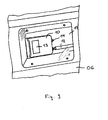
- a data storage device 10 is mounted in a recess. It is protected from the outside by a cover 11 (see also Fig. 9 ). To protect the container wall 02 against the ingress of sharp objects can on the outside guard rails 15 in particularly at risk areas.
- the guard rails 15 may be made for example of a metal sheet.
- the inside structure of the container 01 is made Fig. 2 seen.
- the melt storage elements 16 are filled with a paraffin-containing melt storage material, whereas the melt storage elements 17 contain a salt solution.
- the melt storage elements 16 and 17 serve mounting rails 18 (see also Fig. 3 ), which engage round the melt storage elements 16 and 17 in each case at the upper or lower edge in a form-fitting manner. In this way, the melt storage elements 16 and 17 can be easily replaced by being inserted from the door side into the mounting rails 18.
- the melt storage elements 16 and 17 are fixed to the inside of the container wall 02. This type of attachment allows in particular, the melting storage elements 16 and 17 without tools to assemble or disassemble.
- each inspection openings 19 are provided, whose function will be explained in more detail below.
- a sealing lip 20 is fixed on the inside, with the closing of the door member 06, the parting line between the door member 06 on the one hand and the edge of the two opposite side wall elements 03 and the edge of the ceiling element 05 and the bottom element 04 is sealed.
- Fig. 3 the container 01 is shown schematically in cross-section from the front.
- the flat, namely plate-shaped melt storage elements 16 and 17 are arranged parallel to the container wall 02 on the inner side 21 of the container 01.
- the container wall 02 itself is double-walled from a dimensionally stable outer wall 22 and a likewise dimensionally stable inner wall 23 constructed. Between this mechanically stable double wall of outer wall 22 and inner wall 23 provided for isolation vacuum insulation elements 24 are arranged. Between the vacuum insulation elements 24 and the outer wall 22 impact protection elements 25 are provided made of foamed plastic. The Size relationships between outer wall 22, inner wall 23, the vacuum insulation elements 24 and the impact protection elements 25 are in Fig. 3 only indicated in principle. The exact structure of the structure of the container wall 02 is off Fig. 4 seen.
- FIG. 4 illustrated perspective cross section through the container wall 02 shows that the outer wall 22 and the inner wall 23 are each made of a sandwich material.
- an inner core layer 26 of plywood and an inner core layer 27 of foamed plastic are each covered on the outside by cover layers 28 of fiber-reinforced plastic.
- Fig. 5 a possible embodiment of dimensionally stable melt storage containers 29 is shown. By filling the containers 29 with a suitable melt storage material, the various types of melt storage elements 16 and 17 can be made.
- Fig. 6 the arrangement of the vacuum insulation panels 24 in a side wall 03 is exemplified.
- four vacuum insulation elements 24 are arranged adjacent to each other in all side wall elements 03 and correspondingly also in the bottom element 04, in the ceiling element 05 and in the door element 06. This ensures that if a vacuum insulation element is damaged, for example caused by a microleakage, not all the insulation in the corresponding container wall fails. Rather, a sufficient insulation of the container 01 is still given in total in case of failure of a single vacuum insulation element.
- the flat, formed in the manner of thermal insulation panels vacuum insulation elements 24 touch each other in butt joints 30. In order to minimize the heat is transferred in the butt joints 30, an insulating material can be arranged in the butt joints 30.
- vacuum insulation elements 24 should, if possible, have no projecting film tabs so that vacuum insulation elements 24 can be mounted in the butt joints 30 as closely as possible.
- a further layer of vacuum insulation elements may also be provided in the container wall 02, wherein in the case of several layers, the butt joints 30 should, if possible, be offset from each other.
- each vacuum insulation element 24 there is a control system 31 for controlling the internal gas pressure.
- the four control systems 31 of the four vacuum insulation elements 24 are each adjacent to each other in the middle of the container wall arranged so that the four different control systems 31 are accessible through a single access opening 19 therethrough.
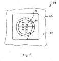
- Fig. 7 the inspection opening 19 is shown enlarged with the four arranged behind a cover 32 control systems 31.
- the cover 32 is removed and placed a test head of a diagnostic device on the control systems 31.
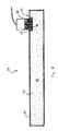
- Structure and function of the control system 31 and structure of the vacuum insulation elements 24 are made Fig. 8 seen.
- the in Fig. 8 shown cross section through the vacuum insulation elements 24 shows an open-pore base body 33 which is gas-tight with a film 34 spanned.
- the gas-tight interior 35 formed by the film 34 is evacuated in order to give the vacuum insulation element 24 the desired insulation properties.
- the control system 31 is placed on the inside of the film 34, which consists of a metal plate 36 and an intermediate layer 37. With a test head 38, a defined temperature jump can then be applied to the control system 31, wherein from the signal response to the temperature jump, the internal gas pressure in the interior 35 can be derived.
- the data storage device 10 is connected via a cable 12 with an internal temperature sensor for measuring the temperature in the interior 07 and with an outside temperature sensor for measuring the ambient temperature surrounding the container 01. At regular intervals, the internal temperature and the outside temperature are measured and the resulting measurement data stored in the data storage device 10 for documentation purposes.
- the current internal temperature or the current outside temperature can be displayed and read from the outside through the transparent cover 11.
- an unillustrated GPS receiver can be connected to the data storage device 10, so that the position data of the container 01 can be stored with the data storage device 10 for documentation purposes.
- the function of the container 01 for temperature insulation is based on the in 10 to FIG. 12 illustrated temperature curves are exemplified.
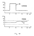
- Fig. 10 a situation is schematically illustrated in which the container 01 is exposed to an outside temperature profile 39.
- the corresponding change in the internal temperature in the interior 07 of the container 01 is presented with the internal temperature profile 40.
- the outdoor temperature profile 39 includes a temperature jump from 10 ° C to 30 ° C over a period of 6 hours.
- This change in the outside temperature initially leads to no temperature change in the interior 07, because the amounts of heat that are transmitted through the vacuum insulation elements 24 are buffered by the melt storage elements 16 and 17 by phase transformation of the melt storage material. Only after a time delay, when large quantities of the melt storage material have already undergone a phase transformation, the internal temperature in the interior 07 increases very slowly.
- Out Fig. 11 is a second outdoor temperature profile 41 and the resulting internal temperature profile 42 in the interior 07 of the container 01 offered.
- the outdoor temperature profile 41 goes through after the positive temperature jump to 30 ° C immediately thereafter a negative temperature jump to just over 0 ° C. Also the negative temperature jump lasts 6 hours. Also, the negative temperature jump is buffered by the melt storage elements 16 and 17, wherein the melt storage elements in turn regenerate by lowering the temperature, so that a subsequent positive temperature jump can in turn be readily buffered.
- a real outdoor temperature profile 43 and a resulting indoor temperature profile 44 are plotted, which were logged in a long-term trial over 210 hours.
- the different curves of the outside temperature profile 43 and the inside temperature profile 44 correspond to the different measuring points outside or within the container 01.
- Fig. 11 Immediately apparent, the internal temperature remains despite a considerable fluctuations in the outside temperature within a narrow temperature band, so that temperature-sensitive goods in the interior of the container 07 are effectively protected from excessive temperature fluctuations.
Landscapes
- Engineering & Computer Science (AREA)
- Chemical & Material Sciences (AREA)
- Combustion & Propulsion (AREA)
- Physics & Mathematics (AREA)
- Mechanical Engineering (AREA)
- Thermal Sciences (AREA)
- General Engineering & Computer Science (AREA)
- Packages (AREA)
Applications Claiming Priority (2)
| Application Number | Priority Date | Filing Date | Title |
|---|---|---|---|
| DE10322764A DE10322764A1 (de) | 2003-05-19 | 2003-05-19 | Container mit Vakuumisolation und Schmelzspeichermaterialien |
| EP04738481.3A EP1625338B2 (fr) | 2003-05-19 | 2004-05-05 | Conteneur isolation thermique |
Related Parent Applications (2)
| Application Number | Title | Priority Date | Filing Date |
|---|---|---|---|
| EP04738481.3A Division-Into EP1625338B2 (fr) | 2003-05-19 | 2004-05-05 | Conteneur isolation thermique |
| EP04738481.3A Division EP1625338B2 (fr) | 2003-05-19 | 2004-05-05 | Conteneur isolation thermique |
Publications (2)
| Publication Number | Publication Date |
|---|---|
| EP2876389A1 true EP2876389A1 (fr) | 2015-05-27 |
| EP2876389B1 EP2876389B1 (fr) | 2018-01-10 |
Family
ID=33461829
Family Applications (3)
| Application Number | Title | Priority Date | Filing Date |
|---|---|---|---|
| EP04738481.3A Expired - Lifetime EP1625338B2 (fr) | 2003-05-19 | 2004-05-05 | Conteneur isolation thermique |
| EP20156390.5A Expired - Lifetime EP3671078B1 (fr) | 2003-05-19 | 2004-05-05 | Récipient à isolation thermique |
| EP14004268.0A Revoked EP2876389B1 (fr) | 2003-05-19 | 2004-05-05 | Récipient à isolation thermique |
Family Applications Before (2)
| Application Number | Title | Priority Date | Filing Date |
|---|---|---|---|
| EP04738481.3A Expired - Lifetime EP1625338B2 (fr) | 2003-05-19 | 2004-05-05 | Conteneur isolation thermique |
| EP20156390.5A Expired - Lifetime EP3671078B1 (fr) | 2003-05-19 | 2004-05-05 | Récipient à isolation thermique |
Country Status (4)
| Country | Link |
|---|---|
| US (1) | US20070051734A1 (fr) |
| EP (3) | EP1625338B2 (fr) |
| DE (1) | DE10322764A1 (fr) |
| WO (1) | WO2004104498A2 (fr) |
Cited By (4)
| Publication number | Priority date | Publication date | Assignee | Title |
|---|---|---|---|---|
| EP3604986A1 (fr) | 2018-08-03 | 2020-02-05 | va-Q-tec AG | Conteneur à palettes destiné au transport de marchandises sensibles à la température |
| US12202665B2 (en) | 2021-07-15 | 2025-01-21 | Pelican Biothermal, Llc | Phase change material panel and passive thermally controlled shipping container employing the panels |
| US12540028B2 (en) | 2019-09-05 | 2026-02-03 | Cold Chain Technologies, Llc | Shipping system for temperature-sensitive materials |
| WO2026038009A1 (fr) | 2024-08-12 | 2026-02-19 | Anderson Marcus Julian Peter Odell | Dispositif d'expédition en chaîne du froid et système de régulation de température |
Families Citing this family (59)
| Publication number | Priority date | Publication date | Assignee | Title |
|---|---|---|---|---|
| DE10322764A1 (de) | 2003-05-19 | 2004-12-30 | Va-Q-Tec Ag | Container mit Vakuumisolation und Schmelzspeichermaterialien |
| DE102006045471A1 (de) * | 2006-09-26 | 2008-04-03 | Va-Q-Tec Ag | Verfahren zur Bestimmung des Gasdruckes in evakuierten Körpern |
| CA2699413C (fr) | 2007-09-11 | 2013-09-10 | Cold Chain Technologies, Llc | Dispositif d'expedition de palette isolee et procedes de realisation et d'utilisation de ce dispositif |
| US7823394B2 (en) * | 2007-11-02 | 2010-11-02 | Reflect Scientific, Inc. | Thermal insulation technique for ultra low temperature cryogenic processor |
| DE102009004353A1 (de) * | 2009-01-08 | 2010-07-15 | SCHÜCO International KG | Vorrichtung und Verfahren zur Raumtemperierung und thermischen Raumkonditionierung |
| US20100200599A1 (en) * | 2009-02-10 | 2010-08-12 | Robert Molthen | Vacuum insulated container |
| TW201205267A (en) * | 2010-07-26 | 2012-02-01 | Wistron Corp | Detecting device capable of economizing electricity and detecting method thereof |
| FR2974353B1 (fr) * | 2011-04-19 | 2014-06-13 | Emball Iso | Dispositif de conditionnement isotherme pour produits thermosensibles |
| US20130255306A1 (en) * | 2012-03-27 | 2013-10-03 | William T. Mayer | Passive thermally regulated shipping container employing phase change material panels containing dual immiscible phase change materials |
| US9140481B2 (en) * | 2012-04-02 | 2015-09-22 | Whirlpool Corporation | Folded vacuum insulated structure |
| DE102012022398B4 (de) * | 2012-11-16 | 2019-03-21 | delta T Gesellschaft für Medizintechnik mbH | Modularer Isolierbehälter |
| DE102012025192A1 (de) * | 2012-12-10 | 2014-06-12 | Va-Q-Tec Ag | Verfahren und Vorrichtung zur Vorkonditionierung von Latentwärmespeicherelementen |
| DE202013001161U1 (de) | 2012-12-11 | 2013-03-28 | Va-Q-Tec Ag | Flaschenkühler und Latentwärmespeicherelement für einen Flaschenkühler |
| DE102013002555A1 (de) | 2012-12-18 | 2014-06-18 | Va-Q-Tec Ag | Verfahren und Vorrichtung zur Vorkonditionierung von Latentwärmespeicherelementen |
| FR3001721A1 (fr) * | 2013-02-05 | 2014-08-08 | Sofrigam | Systeme et procede pour garantir le respect de conditions de temperature pour des produits transportes dans une caisse isotherme. |
| US11248830B2 (en) * | 2014-04-04 | 2022-02-15 | Sunwell Engineering Company Limited | Storage unit for maintaining a generally constant temperature |
| DE102014007987A1 (de) | 2014-05-30 | 2015-12-03 | Va-Q-Tec Ag | Transportbehältersystem |
| DE202014004515U1 (de) | 2014-05-30 | 2015-09-03 | Va-Q-Tec Ag | Transportbehältersystem |
| GB2530077A (en) | 2014-09-12 | 2016-03-16 | Peli Biothermal Ltd | Thermally insulated containers |
| DE102014015770A1 (de) | 2014-10-27 | 2016-04-28 | Va-Q-Tec Ag | Kastenförmiger Transportbehälter |
| DE202014008489U1 (de) | 2014-10-27 | 2016-01-28 | Va-Q-Tec Ag | Kastenförmiger Transportbehälter |
| DE102014016393A1 (de) | 2014-11-07 | 2016-05-12 | Va-Q-Tec Ag | Transportbehälter |
| DE202014008814U1 (de) | 2014-11-07 | 2016-02-11 | Va-Q-Tec Ag | Transportbehälter |
| DE102015007277A1 (de) | 2015-06-10 | 2016-12-15 | Va-Q-Tec Ag | Wärmeisolierender Korpus für ein Kühlgerät sowie Kühlgerät mit einem wärmeisolierenden Korpus |
| DE202015004047U1 (de) | 2015-06-10 | 2016-09-14 | Va-Q-Tec Ag | Wärmesolierender Korpus für ein Kühlgerät sowie Kühlgerät mit einem wärmeisolierenden Korpus |
| CN108351146B (zh) * | 2015-09-11 | 2021-04-20 | 确保冷藏有限公司 | 便携式制冷设备 |
| US10604326B2 (en) | 2015-10-06 | 2020-03-31 | Cold Chain Technologies, Llc. | Pallet cover comprising one or more temperature-control members and kit for use in making the pallet cover |
| EP3359889B1 (fr) * | 2015-10-06 | 2020-08-05 | Cold Chain Technologies, LLC | Système d'expédition isolé thermiquement pour charge palettisable |
| US11591133B2 (en) | 2015-10-06 | 2023-02-28 | Cold Chain Technologies, Llc | Pallet cover comprising one or more temperature-control members and kit for use in making the pallet cover |
| US11964795B2 (en) | 2015-10-06 | 2024-04-23 | Cold Chain Technologies, Llc | Device comprising one or more temperature-control members and kit for use in making the device |
| US10583978B2 (en) | 2015-10-06 | 2020-03-10 | Cold Chain Technologies, Llc | Pallet cover compromising one or more temperature-control members and kit for use in making the pallet cover |
| DE202016001097U1 (de) * | 2016-01-28 | 2017-05-02 | Va-Q-Tec Ag | Transportbehältersystem |
| EP3228960A1 (fr) | 2016-04-08 | 2017-10-11 | ROTTER, Thomas | Élement sous vide, emballage sous vide et caisson sous vide |
| JP6925106B2 (ja) * | 2016-07-19 | 2021-08-25 | 富士フイルム富山化学株式会社 | 搬送装置 |
| JP6870985B2 (ja) * | 2016-12-28 | 2021-05-12 | 旭ファイバーグラス株式会社 | 真空断熱材 |
| DE102017000622B4 (de) | 2017-01-25 | 2023-10-26 | Va-Q-Tec Ag | Verfahren zum Präparieren eines Transportbehälters |
| NL2018588B1 (en) * | 2017-03-28 | 2018-03-26 | Turtle B V | Flight case suited to transport musical instruments |
| WO2018208986A1 (fr) | 2017-05-09 | 2018-11-15 | Cold Chain Technologies, Inc. | Système d'expédition pour le stockage et/ou le transport de matériaux sensibles à la température |
| US11511928B2 (en) | 2017-05-09 | 2022-11-29 | Cold Chain Technologies, Llc | Shipping system for storing and/or transporting temperature-sensitive materials |
| FR3076285B1 (fr) * | 2018-01-03 | 2021-01-15 | Sofrigam | Dispositif et procede pour garantir un releve de temperature fiable dans une caisse thermo-isolante. |
| US10935299B2 (en) * | 2018-06-13 | 2021-03-02 | Cedric Davis | Quick freeze cooler |
| US11999559B2 (en) | 2018-08-10 | 2024-06-04 | Cold Chain Technologies, Llc | Apparatus and method for protectively covering temperature sensitive products |
| DE202018104807U1 (de) | 2018-08-21 | 2018-08-28 | Va-Q-Tec Ag | Vakuumgedämmter Stapelbehälter für den temperaturgeführten Transport von Nahrungsmitteln |
| DE202018106306U1 (de) | 2018-11-06 | 2018-11-13 | Va-Q-Tec Ag | Temperierbarer Container mit Vakuumisolationselementen |
| US11137190B2 (en) | 2019-06-28 | 2021-10-05 | Cold Chain Technologies, Llc | Method and system for maintaining temperature-sensitive materials within a desired temperature range for a period of time |
| PL241881B1 (pl) * | 2020-02-03 | 2022-12-19 | Univ West Pomeranian Szczecin Tech | Sposób zabezpieczania przed szybką utratą parametrów termicznych chłodniczego kontenera z szybko psującym się ładunkiem i pokrywa do zabezpieczania przed szybką utratą parametrów termicznych chłodniczego kontenera z szybko psującym się ładunkiem |
| US20210403224A1 (en) * | 2020-06-24 | 2021-12-30 | World Courier Management Limited | Packaging system for transporting temperature-sensitive products |
| WO2022006547A1 (fr) | 2020-07-02 | 2022-01-06 | Cold Chain Technologies, Llc | Système d'expédition permettant de stocker et/ou de transporter des matières sensibles à la température |
| DE202020104675U1 (de) | 2020-08-12 | 2020-09-30 | Va-Q-Tec Ag | Transportcontainer zum temperaturgeführten Transport von temperatursensiblen Gütern |
| US20220081200A1 (en) * | 2020-09-11 | 2022-03-17 | Sonoco Development, Inc. | Passive Temperature Controlled Packaging System as a ULD |
| EP4288351A4 (fr) * | 2021-02-03 | 2024-12-25 | Peli Biothermal LLC | Conteneur d'expédition àconditionnement sur place par commande thermique passive |
| US12366400B2 (en) | 2021-03-04 | 2025-07-22 | Cold Chain Technologies, Llc | Shipping system for storing and/or transporting temperature-sensitive materials |
| AT524553B1 (de) * | 2021-07-30 | 2022-07-15 | Rep Ip Ag | Versandbehälter für temperaturempfindliches Transportgut |
| WO2024102719A2 (fr) * | 2022-11-07 | 2024-05-16 | Peli Biothermal Llc | Conteneur d'expédition à commande thermique passive et procédés de conditionnement thermique en place, d'évaluation holistique d'intégrité thermique, de réparation ou de remplacement de composants défectueux et de chargement |
| EP4410704A1 (fr) | 2023-01-31 | 2024-08-07 | Rep Ip Ag | Récipient de transport pour le transport de produits sensibles à la température |
| FR3148016B1 (fr) * | 2023-04-24 | 2025-06-13 | Sofrigam | Système amélioré de caisse de transport thermiquement isolante. |
| US12163734B1 (en) | 2023-09-15 | 2024-12-10 | Sharkninja Operating Llc | Insulated container with a drawer |
| USD1103709S1 (en) | 2023-09-15 | 2025-12-02 | Sharkninja Operating Llc | Cooler |
| US12129099B1 (en) | 2024-03-13 | 2024-10-29 | Sharkninja Operating Llc | Insulated container with a drawer |
Citations (4)
| Publication number | Priority date | Publication date | Assignee | Title |
|---|---|---|---|---|
| JPH0868591A (ja) * | 1994-08-29 | 1996-03-12 | Toshiba Corp | 断熱箱体 |
| WO1997012100A1 (fr) * | 1995-09-25 | 1997-04-03 | Owens Corning | Panneaux isolants modulaires et structures isolees |
| US6062040A (en) | 1996-08-30 | 2000-05-16 | Vesture Corporation | Insulated chest and method |
| JP2002264717A (ja) * | 2001-03-12 | 2002-09-18 | Isuzu Motors Ltd | 保冷車のボディ |
Family Cites Families (39)
| Publication number | Priority date | Publication date | Assignee | Title |
|---|---|---|---|---|
| US4091842A (en) | 1977-07-28 | 1978-05-30 | The Dow Chemical Company | Resealable sealing assembly for inspection port hole |
| US4313993A (en) | 1980-04-14 | 1982-02-02 | Mcglory Joseph J | Laminated insulation |
| US4351271A (en) | 1980-09-04 | 1982-09-28 | Paul Mueller Company | Refrigerated receiver |
| JPS63188481U (fr) * | 1987-05-22 | 1988-12-02 | ||
| US4845959A (en) | 1988-06-27 | 1989-07-11 | Fort Valley State College | Fruits and vegetables precooling, shipping and storage container |
| SE9100649L (sv) | 1991-03-05 | 1992-05-25 | Eurotainer Ab | Transportbehaallare foer temperaturkaensliga varor |
| JPH04302978A (ja) * | 1991-03-28 | 1992-10-26 | Matsushita Refrig Co Ltd | 蓄冷型保冷庫 |
| US5351718A (en) | 1993-06-28 | 1994-10-04 | Barton David D | Access plug flange |
| US5522216A (en) | 1994-01-12 | 1996-06-04 | Marlow Industries, Inc. | Thermoelectric refrigerator |
| US5518033A (en) | 1994-09-19 | 1996-05-21 | Sepco Industries | Vessel inspection plug and method of installing same in vessel |
| US5520220A (en) | 1995-08-29 | 1996-05-28 | Barton; David D. | Access mounting flange for cold temperature chemical processing equipment |
| US5669233A (en) | 1996-03-11 | 1997-09-23 | Tcp Reliable Inc. | Collapsible and reusable shipping container |
| US7253731B2 (en) | 2001-01-23 | 2007-08-07 | Raymond Anthony Joao | Apparatus and method for providing shipment information |
| US5950450A (en) * | 1996-06-12 | 1999-09-14 | Vacupanel, Inc. | Containment system for transporting and storing temperature-sensitive materials |
| US5865346A (en) | 1997-01-07 | 1999-02-02 | Del Zotto; William M. | Self-contained fueling system and method |
| JPH10239199A (ja) † | 1997-02-28 | 1998-09-11 | Toshiba Corp | 真空度測定装置 |
| US5924302A (en) | 1997-03-27 | 1999-07-20 | Foremost In Packaging Systems, Inc. | Insulated shipping container |
| JPH10292984A (ja) | 1997-04-18 | 1998-11-04 | Hitachi Ltd | 冷蔵庫 |
| FR2762899A1 (fr) | 1997-05-02 | 1998-11-06 | Applic Gaz Sa | Contenant portatif a usage refrigerant, par exemple glaciere |
| US5893479A (en) | 1997-07-17 | 1999-04-13 | Berberat; Henry | Storage tank vault |
| US5899088A (en) * | 1998-05-14 | 1999-05-04 | Throwleigh Technologies, L.L.C. | Phase change system for temperature control |
| US6065314A (en) | 1998-05-22 | 2000-05-23 | Nicholson; John W. | Lock for freight containers |
| US6244458B1 (en) | 1998-07-09 | 2001-06-12 | Thermo Solutions, Inc. | Thermally insulated container |
| US6209343B1 (en) * | 1998-09-29 | 2001-04-03 | Life Science Holdings, Inc. | Portable apparatus for storing and/or transporting biological samples, tissues and/or organs |
| GB9900312D0 (en) | 1999-01-07 | 1999-02-24 | Unilever Plc | Freezer cabinet |
| WO2000048753A1 (fr) | 1999-02-18 | 2000-08-24 | Kyowa Co., Ltd. | Décomposeur thermique de déchets |
| DE60036572T2 (de) * | 1999-04-12 | 2008-10-23 | Isuzu Motors Ltd. | Wärmedämmendes Mauerelement und Verfahren zu dessen Herstellung |
| US6470821B1 (en) | 1999-05-26 | 2002-10-29 | Insulated Shipping Containers | Method and apparatus for the evaluation of vacuum insulation panels |
| DE10015876A1 (de) * | 2000-03-30 | 2001-10-11 | Jobst H Kerspe | Vakuum-Isolations-Element |
| DE10058566C2 (de) | 2000-08-03 | 2002-10-31 | Va Q Tec Ag | Folienumhüllter, evakuierter Wärmedämmkörper und Herstellungsverfahren für diesen |
| AUPR312901A0 (en) * | 2001-02-15 | 2001-03-08 | Creative Packaging Services Pty Ltd | Temperature retaining container |
| DE10148587C1 (de) * | 2001-03-19 | 2002-11-28 | Hans Zucker Gmbh & Co Kg | Isolierende Komponente für wechselbar temperierfähiges Behältnis |
| US6718776B2 (en) † | 2001-07-10 | 2004-04-13 | University Of Alabama In Huntsville | Passive thermal control enclosure for payloads |
| US20030082357A1 (en) * | 2001-09-05 | 2003-05-01 | Cem Gokay | Multi-layer core for vacuum insulation panel and insulated container including vacuum insulation panel |
| JP2003106760A (ja) * | 2001-09-27 | 2003-04-09 | Mitsubishi Corp | 高断熱複合パネル及びそれを用いた構造体 |
| DE10158441A1 (de) | 2001-11-29 | 2003-06-18 | Va Q Tec Ag | Gasdrucksensor für folienumhüllte Vakuumdämmpaneele |
| DE10215213C1 (de) | 2002-04-06 | 2003-09-11 | Va Q Tec Ag | Vorrichtung und Verfahren zur Messung des Gasdruckes in evakuierten Dämmplatten |
| DE10243120A1 (de) | 2002-09-17 | 2004-03-25 | N. Romijn B.V. | Transportbehälter für temperaturempfindliche Güter |
| DE10322764A1 (de) | 2003-05-19 | 2004-12-30 | Va-Q-Tec Ag | Container mit Vakuumisolation und Schmelzspeichermaterialien |
-
2003
- 2003-05-19 DE DE10322764A patent/DE10322764A1/de not_active Withdrawn
-
2004
- 2004-05-05 EP EP04738481.3A patent/EP1625338B2/fr not_active Expired - Lifetime
- 2004-05-05 US US10/557,398 patent/US20070051734A1/en not_active Abandoned
- 2004-05-05 EP EP20156390.5A patent/EP3671078B1/fr not_active Expired - Lifetime
- 2004-05-05 EP EP14004268.0A patent/EP2876389B1/fr not_active Revoked
- 2004-05-05 WO PCT/DE2004/000953 patent/WO2004104498A2/fr not_active Ceased
Patent Citations (4)
| Publication number | Priority date | Publication date | Assignee | Title |
|---|---|---|---|---|
| JPH0868591A (ja) * | 1994-08-29 | 1996-03-12 | Toshiba Corp | 断熱箱体 |
| WO1997012100A1 (fr) * | 1995-09-25 | 1997-04-03 | Owens Corning | Panneaux isolants modulaires et structures isolees |
| US6062040A (en) | 1996-08-30 | 2000-05-16 | Vesture Corporation | Insulated chest and method |
| JP2002264717A (ja) * | 2001-03-12 | 2002-09-18 | Isuzu Motors Ltd | 保冷車のボディ |
Cited By (4)
| Publication number | Priority date | Publication date | Assignee | Title |
|---|---|---|---|---|
| EP3604986A1 (fr) | 2018-08-03 | 2020-02-05 | va-Q-tec AG | Conteneur à palettes destiné au transport de marchandises sensibles à la température |
| US12540028B2 (en) | 2019-09-05 | 2026-02-03 | Cold Chain Technologies, Llc | Shipping system for temperature-sensitive materials |
| US12202665B2 (en) | 2021-07-15 | 2025-01-21 | Pelican Biothermal, Llc | Phase change material panel and passive thermally controlled shipping container employing the panels |
| WO2026038009A1 (fr) | 2024-08-12 | 2026-02-19 | Anderson Marcus Julian Peter Odell | Dispositif d'expédition en chaîne du froid et système de régulation de température |
Also Published As
| Publication number | Publication date |
|---|---|
| DE10322764A1 (de) | 2004-12-30 |
| EP1625338B2 (fr) | 2023-04-12 |
| WO2004104498A2 (fr) | 2004-12-02 |
| EP1625338B1 (fr) | 2020-02-12 |
| EP2876389B1 (fr) | 2018-01-10 |
| US20070051734A1 (en) | 2007-03-08 |
| WO2004104498A3 (fr) | 2005-03-31 |
| EP3671078B1 (fr) | 2024-02-14 |
| EP3671078A1 (fr) | 2020-06-24 |
| EP1625338A2 (fr) | 2006-02-15 |
Similar Documents
| Publication | Publication Date | Title |
|---|---|---|
| EP2876389B1 (fr) | Récipient à isolation thermique | |
| EP3687922B1 (fr) | Conteneur de transport | |
| EP2354729B1 (fr) | Dispositif de réglage de températures très basses | |
| WO2014076586A1 (fr) | Conteneur isotherme modulaire et procédé pour l'utiliser | |
| DE102015113693A1 (de) | Thermoisolierter Transportbehälter mit an den Wänden anliegender Thermoisolierung sowie Wandaufbau eines derartigen Behälters | |
| EP3921583B1 (fr) | Contenant de transport | |
| DE102006032435A1 (de) | Transportbehälter zur Kühlhaltung von gefrorenem Gut | |
| DE4342947A1 (de) | Wandelement | |
| EP2670238B1 (fr) | Installation frigorifique destinée notamment à la cryoconservation d'échantillons biologiques, équipée de dispositifs pour un cas d'avarie | |
| EP0398232A1 (fr) | Conteneur pour le transport à température et atmosphère contrôlées de denrées périssables | |
| WO2008037451A2 (fr) | Procédé et dispositif destinés à déterminer la pression gazeuse dans des corps évacués | |
| DE8801345U1 (de) | Schutzvorrichtung für temperaturempfindliche Güter | |
| DE102008029171A1 (de) | Transportsystem mit einem Isolierbehälter | |
| DE202010011159U1 (de) | Kühlbox | |
| DE202020107340U1 (de) | Isolationsbehälter für den temperaturgeführten Transport von pharmazeutischen Produkten | |
| DE202004016939U1 (de) | Tragbarer wärmeisolierter Transportbehälter | |
| DE202008013573U1 (de) | Transportsystem mit einem Isolierbehälter | |
| DE102004053113A1 (de) | Tragbarer wärmeisolierter Transportbehälter | |
| DE102020111660A1 (de) | Steckverbinder mit Informationsgeber | |
| WO2018015337A1 (fr) | Véhicule frigorifique et procédé de transport d'échantillons cryogéniques | |
| DE60013908T2 (de) | Behälter für empfindliche fracht | |
| DE102006040697B3 (de) | Betriebs-, Lager- und Transportbehälter für IT-Geräte | |
| WO2005108163A1 (fr) | Systeme de paroi de separation de zone de refrigeration | |
| DE102007048466A1 (de) | Luft-Cargo-Transportgerät | |
| DE202007014306U1 (de) | Kühlfahrzeug |
Legal Events
| Date | Code | Title | Description |
|---|---|---|---|
| PUAI | Public reference made under article 153(3) epc to a published international application that has entered the european phase |
Free format text: ORIGINAL CODE: 0009012 |
|
| 17P | Request for examination filed |
Effective date: 20141218 |
|
| AC | Divisional application: reference to earlier application |
Ref document number: 1625338 Country of ref document: EP Kind code of ref document: P |
|
| AK | Designated contracting states |
Kind code of ref document: A1 Designated state(s): CH DE FR GB IT LI |
|
| R17P | Request for examination filed (corrected) |
Effective date: 20151015 |
|
| RBV | Designated contracting states (corrected) |
Designated state(s): CH DE FR GB IT LI |
|
| 17Q | First examination report despatched |
Effective date: 20160713 |
|
| STAA | Information on the status of an ep patent application or granted ep patent |
Free format text: STATUS: EXAMINATION IS IN PROGRESS |
|
| GRAP | Despatch of communication of intention to grant a patent |
Free format text: ORIGINAL CODE: EPIDOSNIGR1 |
|
| STAA | Information on the status of an ep patent application or granted ep patent |
Free format text: STATUS: GRANT OF PATENT IS INTENDED |
|
| INTG | Intention to grant announced |
Effective date: 20171009 |
|
| GRAS | Grant fee paid |
Free format text: ORIGINAL CODE: EPIDOSNIGR3 |
|
| GRAA | (expected) grant |
Free format text: ORIGINAL CODE: 0009210 |
|
| STAA | Information on the status of an ep patent application or granted ep patent |
Free format text: STATUS: THE PATENT HAS BEEN GRANTED |
|
| RAP1 | Party data changed (applicant data changed or rights of an application transferred) |
Owner name: VA-Q-TEC AG |
|
| AC | Divisional application: reference to earlier application |
Ref document number: 1625338 Country of ref document: EP Kind code of ref document: P |
|
| AK | Designated contracting states |
Kind code of ref document: B1 Designated state(s): CH DE FR GB IT LI |
|
| REG | Reference to a national code |
Ref country code: CH Ref legal event code: EP |
|
| REG | Reference to a national code |
Ref country code: DE Ref legal event code: R096 Ref document number: 502004015633 Country of ref document: DE |
|
| REG | Reference to a national code |
Ref country code: FR Ref legal event code: PLFP Year of fee payment: 15 |
|
| REG | Reference to a national code |
Ref country code: DE Ref legal event code: R026 Ref document number: 502004015633 Country of ref document: DE |
|
| PLBI | Opposition filed |
Free format text: ORIGINAL CODE: 0009260 |
|
| PLAX | Notice of opposition and request to file observation + time limit sent |
Free format text: ORIGINAL CODE: EPIDOSNOBS2 |
|
| 26 | Opposition filed |
Opponent name: PELICAN BIOTHERMAL LLC Effective date: 20181010 |
|
| PLBB | Reply of patent proprietor to notice(s) of opposition received |
Free format text: ORIGINAL CODE: EPIDOSNOBS3 |
|
| APBM | Appeal reference recorded |
Free format text: ORIGINAL CODE: EPIDOSNREFNO |
|
| APBP | Date of receipt of notice of appeal recorded |
Free format text: ORIGINAL CODE: EPIDOSNNOA2O |
|
| APAH | Appeal reference modified |
Free format text: ORIGINAL CODE: EPIDOSCREFNO |
|
| APBQ | Date of receipt of statement of grounds of appeal recorded |
Free format text: ORIGINAL CODE: EPIDOSNNOA3O |
|
| REG | Reference to a national code |
Ref country code: FR Ref legal event code: PLFP Year of fee payment: 19 |
|
| PGFP | Annual fee paid to national office [announced via postgrant information from national office to epo] |
Ref country code: IT Payment date: 20220524 Year of fee payment: 19 Ref country code: GB Payment date: 20220520 Year of fee payment: 19 Ref country code: FR Payment date: 20220523 Year of fee payment: 19 Ref country code: DE Payment date: 20220519 Year of fee payment: 19 |
|
| PGFP | Annual fee paid to national office [announced via postgrant information from national office to epo] |
Ref country code: CH Payment date: 20220519 Year of fee payment: 19 |
|
| REG | Reference to a national code |
Ref country code: DE Ref legal event code: R103 Ref document number: 502004015633 Country of ref document: DE Ref country code: DE Ref legal event code: R064 Ref document number: 502004015633 Country of ref document: DE |
|
| APBU | Appeal procedure closed |
Free format text: ORIGINAL CODE: EPIDOSNNOA9O |
|
| RDAF | Communication despatched that patent is revoked |
Free format text: ORIGINAL CODE: EPIDOSNREV1 |
|
| STAA | Information on the status of an ep patent application or granted ep patent |
Free format text: STATUS: PATENT REVOKED |
|
| RDAG | Patent revoked |
Free format text: ORIGINAL CODE: 0009271 |
|
| REG | Reference to a national code |
Ref country code: CH Ref legal event code: PL |
|
| 27W | Patent revoked |
Effective date: 20221207 |
|
| GBPR | Gb: patent revoked under art. 102 of the ep convention designating the uk as contracting state |
Effective date: 20221207 |