EP2876396A1 - Verfahren zum Trocknen von Trocknungsgut - Google Patents
Verfahren zum Trocknen von Trocknungsgut Download PDFInfo
- Publication number
- EP2876396A1 EP2876396A1 EP14194493.4A EP14194493A EP2876396A1 EP 2876396 A1 EP2876396 A1 EP 2876396A1 EP 14194493 A EP14194493 A EP 14194493A EP 2876396 A1 EP2876396 A1 EP 2876396A1
- Authority
- EP
- European Patent Office
- Prior art keywords
- value
- air
- dehumidifier
- power value
- fan
- Prior art date
- Legal status (The legal status is an assumption and is not a legal conclusion. Google has not performed a legal analysis and makes no representation as to the accuracy of the status listed.)
- Granted
Links
Images
Classifications
-
- F—MECHANICAL ENGINEERING; LIGHTING; HEATING; WEAPONS; BLASTING
- F26—DRYING
- F26B—DRYING SOLID MATERIALS OR OBJECTS BY REMOVING LIQUID THEREFROM
- F26B3/00—Drying solid materials or objects by processes involving the application of heat
- F26B3/02—Drying solid materials or objects by processes involving the application of heat by convection, i.e. heat being conveyed from a heat source to the materials or objects to be dried by a gas or vapour, e.g. air
- F26B3/06—Drying solid materials or objects by processes involving the application of heat by convection, i.e. heat being conveyed from a heat source to the materials or objects to be dried by a gas or vapour, e.g. air the gas or vapour flowing through the materials or objects to be dried
-
- F—MECHANICAL ENGINEERING; LIGHTING; HEATING; WEAPONS; BLASTING
- F26—DRYING
- F26B—DRYING SOLID MATERIALS OR OBJECTS BY REMOVING LIQUID THEREFROM
- F26B21/00—Arrangements for supplying or controlling air or other gases for drying solid materials or objects
- F26B21/20—Circulating air or gases in closed cycles, e.g. wholly within the drying enclosure
- F26B21/25—Circulating air or gases in closed cycles, e.g. wholly within the drying enclosure partly outside the drying enclosure
-
- F—MECHANICAL ENGINEERING; LIGHTING; HEATING; WEAPONS; BLASTING
- F26—DRYING
- F26B—DRYING SOLID MATERIALS OR OBJECTS BY REMOVING LIQUID THEREFROM
- F26B21/00—Arrangements for supplying or controlling air or other gases for drying solid materials or objects
- F26B21/30—Controlling, e.g. regulating, parameters of gas supply
- F26B21/33—Humidity
- F26B21/333—Humidity by condensing the moisture in the drying medium, which may be recycled, e.g. using a heat pump cycle
-
- F—MECHANICAL ENGINEERING; LIGHTING; HEATING; WEAPONS; BLASTING
- F26—DRYING
- F26B—DRYING SOLID MATERIALS OR OBJECTS BY REMOVING LIQUID THEREFROM
- F26B21/00—Arrangements for supplying or controlling air or other gases for drying solid materials or objects
- F26B21/30—Controlling, e.g. regulating, parameters of gas supply
- F26B21/35—Temperature; Pressure
-
- F—MECHANICAL ENGINEERING; LIGHTING; HEATING; WEAPONS; BLASTING
- F26—DRYING
- F26B—DRYING SOLID MATERIALS OR OBJECTS BY REMOVING LIQUID THEREFROM
- F26B21/00—Arrangements for supplying or controlling air or other gases for drying solid materials or objects
- F26B21/30—Controlling, e.g. regulating, parameters of gas supply
- F26B21/37—Velocity of flow; Quantity of flow
-
- F—MECHANICAL ENGINEERING; LIGHTING; HEATING; WEAPONS; BLASTING
- F26—DRYING
- F26B—DRYING SOLID MATERIALS OR OBJECTS BY REMOVING LIQUID THEREFROM
- F26B23/00—Heating arrangements
- F26B23/001—Heating arrangements using waste heat
- F26B23/002—Heating arrangements using waste heat recovered from dryer exhaust gases
- F26B23/005—Heating arrangements using waste heat recovered from dryer exhaust gases using a closed cycle heat pump system ; using a heat pipe system
-
- F—MECHANICAL ENGINEERING; LIGHTING; HEATING; WEAPONS; BLASTING
- F26—DRYING
- F26B—DRYING SOLID MATERIALS OR OBJECTS BY REMOVING LIQUID THEREFROM
- F26B9/00—Machines or apparatus for drying solid materials or objects at rest or with only local agitation; Domestic airing cupboards
- F26B9/06—Machines or apparatus for drying solid materials or objects at rest or with only local agitation; Domestic airing cupboards in stationary drums or chambers
- F26B9/063—Machines or apparatus for drying solid materials or objects at rest or with only local agitation; Domestic airing cupboards in stationary drums or chambers for drying granular material in bulk, e.g. grain bins or silos with false floor
-
- G—PHYSICS
- G05—CONTROLLING; REGULATING
- G05D—SYSTEMS FOR CONTROLLING OR REGULATING NON-ELECTRIC VARIABLES
- G05D23/00—Control of temperature
-
- G—PHYSICS
- G05—CONTROLLING; REGULATING
- G05D—SYSTEMS FOR CONTROLLING OR REGULATING NON-ELECTRIC VARIABLES
- G05D7/00—Control of flow
-
- Y—GENERAL TAGGING OF NEW TECHNOLOGICAL DEVELOPMENTS; GENERAL TAGGING OF CROSS-SECTIONAL TECHNOLOGIES SPANNING OVER SEVERAL SECTIONS OF THE IPC; TECHNICAL SUBJECTS COVERED BY FORMER USPC CROSS-REFERENCE ART COLLECTIONS [XRACs] AND DIGESTS
- Y02—TECHNOLOGIES OR APPLICATIONS FOR MITIGATION OR ADAPTATION AGAINST CLIMATE CHANGE
- Y02B—CLIMATE CHANGE MITIGATION TECHNOLOGIES RELATED TO BUILDINGS, e.g. HOUSING, HOUSE APPLIANCES OR RELATED END-USER APPLICATIONS
- Y02B30/00—Energy efficient heating, ventilation or air conditioning [HVAC]
- Y02B30/52—Heat recovery pumps, i.e. heat pump based systems or units able to transfer the thermal energy from one area of the premises or part of the facilities to a different one, improving the overall efficiency
-
- Y—GENERAL TAGGING OF NEW TECHNOLOGICAL DEVELOPMENTS; GENERAL TAGGING OF CROSS-SECTIONAL TECHNOLOGIES SPANNING OVER SEVERAL SECTIONS OF THE IPC; TECHNICAL SUBJECTS COVERED BY FORMER USPC CROSS-REFERENCE ART COLLECTIONS [XRACs] AND DIGESTS
- Y02—TECHNOLOGIES OR APPLICATIONS FOR MITIGATION OR ADAPTATION AGAINST CLIMATE CHANGE
- Y02P—CLIMATE CHANGE MITIGATION TECHNOLOGIES IN THE PRODUCTION OR PROCESSING OF GOODS
- Y02P70/00—Climate change mitigation technologies in the production process for final industrial or consumer products
- Y02P70/10—Greenhouse gas [GHG] capture, material saving, heat recovery or other energy efficient measures, e.g. motor control, characterised by manufacturing processes, e.g. for rolling metal or metal working
Definitions
- the present invention relates to a method for drying material to be dried, preferably hay, wherein the material to be dried is fed into a ventilation box with an inflatable box surface, wherein air is drawn in by means of at least one controllable fan and at least partially supplied to a controllable dehumidifier, in which the air is dehumidified , and wherein the at least partially dehumidified air is blown by means of the at least one fan into the ventilation box on the inflatable box surface.
- the air In order to carry out the drying sensibly, the air must not be too cold and may need to be warmed up. In addition, the air can also be specifically heated to the Drying performance continues to increase. At the same time, it is important for the drying that a sufficiently large amount of dehumidified air is blown into the ventilation box or through the hay. This can result in very high energy consumption. In addition, very high energy consumption peaks can occur, depending on how cold the air used is or how much the air must be warmed up in order to use it for drying. Accordingly generous the power supply facilities, such as electrical systems, must be dimensioned, which in turn causes considerable costs.
- the invention is based on the idea that in order to avoid energy consumption peaks, a total power value is determined which corresponds to the sum of an average power consumption of a controllable fan and a controllable dehumidifier.
- the control of the fan and the dehumidifier with frequency converters.
- the power consumption of the fan is adjusted by controlling its speed;
- the power consumption of the dehumidifier is essentially determined by the performance of a compressor of the dehumidifier.
- the fan and the dehumidifier are controlled so that the sum of their power is always less than or equal to the total power value, taking into account an internal temperature of the air in the ventilation box.
- the power supply based on the total power value and not have to interpret it larger.
- the current consumption of the fan and the dehumidifier is constantly measured, and it is continuously determined the amount of air sucked (in m 3 ) per unit time (h) and per square meter box area (m B 2 ) determined.
- the internal temperature is preferably measured in an end region of the ventilation box, wherein the material to be dried or hay is arranged between an initial region of the ventilation box and the end region, on the inflatable box surface.
- the minimum value of the intake air amount of between 200 m 3 / h / m B 2 and 300 m 3 / h / m B 2, preferably at 250 m 3 / h / m B 2 lies.
- the hay is substantially loose in the aeration box, ie, especially not in the form of round bales.
- the inflatable box area is limited to the area on which the round bale rests or rest. This can preferably be realized in such a way that in each case a round bale to be dried is arranged above an opening in an initial region of the ventilation box, wherein the air used for drying is blown through the opening into the ventilation box or directly onto the respective round bale.
- the opening can be a circular hole be executed and is adapted to the diameter of the round bale, ie the diameter of the opening substantially corresponds to the diameter of the round bale and is therefore for example between 1.2 m and 2 m. So that the round bale does not fall into the opening, the opening can be covered, for example, with a grid. Accordingly, in this case setpoint values of the intake air quantity of, for example, about 850 m 3 / h to 2000 m 3 / h per opening or per round bale arise.
- the predetermined value for the internal temperature is 20 ° C to 28 ° C, preferably 20 ° C to 25 ° C.
- the dehumidifier includes a compressor. Furthermore, the dehumidifier includes an evaporator and a condenser. In the evaporator refrigerant is vaporized by the heat of the sucked and flowing through the evaporator air. As a result, the sucked air is cooled below the dew point, and there is a condensation of water on the cold surface of the evaporator, wherein the water in the sequence from the evaporator runs off or drips. Accordingly, the air is dehumidified seen behind the evaporator in a flow direction. By means of the compressor, the gaseous refrigerant is compressed and fed to the condenser, where the hot gaseous refrigerant condenses.
- the refrigerant releases latent heat so that the condenser can be used to heat the dehumidified air.
- the compressor from heat, which can also be used to heat the dehumidified air. That is a warming of the dehumidified air basically without additional heat sources, such as an electric heater, possible.
- the air after it has been passed through an evaporator of the dehumidifier, is heated, preferably by means of a condenser of the dehumidifier and / or by means of a compressor of the dehumidifier.
- the air in a first mode, the air is sucked only from the ventilation box, that in a second mode, the air is at least partially sucked from outside the ventilation box and that switching back and forth between the the first mode and the second mode depending on the internal temperature and / or an outside temperature of the sucked from outside of the ventilation box air and / or the difference between the internal temperature and the outside temperature.
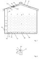
- Fig. 1 schematically a device for drying hay 1 is shown, wherein a method according to the invention can be used.
- the hay 1 is arranged in a ventilation box 2 between an initial region 15 and an end region 16.
- the ventilation box 2 is roofed with a roof 3, so that the hay 1 is protected from the weather.
- the hay 1 rests on a box surface 22.
- the box surface 22 can be flowed in with air by the box surface 22 being realized, for example, by a reinforcing steel grid which rests on grate carriers (not shown) and is arranged at a certain distance, for example 40 cm, above a base 23.
- an air channel 21 is formed in the initial region 15 through which air can be blown onto the box surface 22 or into the ventilation box 2.
- the in Fig. 1 shown device for hay drying a fan 4, wherein the arrows in Fig. 1 possible Symbolize air flows.
- the air to be injected into the ventilation box 2 is first sucked in by means of the fan 4, wherein preferably the entire sucked-in air is sucked through a dehumidifier 5, in which dehumidifier 5 the air is dehumidified.
- the air flow rate can be influenced by a control of the fan 4, ie the amount of air sucked in and thus the amount of air blown into the ventilation box 2 can be regulated.
- the density of the hay 1 can vary - typically between 100 kg / m 3 to 250 kg / m 3 -, which is accompanied by a different resistance for the blown into the ventilation box 2 air. Accordingly, the power or the rotational speed of the fan 4 must be controllable, frequency converters being provided for this purpose (not shown).
- a pressure sensor 19 is arranged in the initial region 15. If the pressure in the starting region 15 or a resulting differential pressure between the starting region 15 and the end region 16 is too great, the fan 4 can be regulated back accordingly. This may be necessary if the density of the hay 1 is too high and affects the air flow too much.
- Frequency converters are also preferably used to control the power of the dehumidifier 5 or a compressor 13 of the dehumidifier 5, wherein the compressor 13 in Fig. 2 , which shows a simplified diagram of the construction of the dehumidifier 5, can be seen. How out Fig. 2 also shows, the dehumidifier 5 further comprises an evaporator 11 and a condenser 12. In the evaporator refrigerant is vaporized by the heat of the sucked and flowing through the evaporator 11 air. As a result, the intake air is below the dew point cooled, and there is a condensation of water on the cold surface of the evaporator 11, wherein the water in the sequence of the evaporator 11 runs off or drips off.
- the air is dehumidified seen behind the evaporator 11 in a flow direction 20.
- the compressor 13 heat from which can also be used to heat the dehumidified air. That is, a warming of the dehumidified air is in principle possible with additional heat sources, such as with an additional electric heater, but not necessary if the already existing heat sources, ie capacitor 12 and / or compressor 13, are used properly.
- the condenser 12 is arranged behind the evaporator 11 in the flow direction 20 and the compressor 13 between the evaporator 11 and the condenser 12.
- the device of Fig. 1 also has a switching flap 6, which is arranged in the end region 16 and can be moved by means of an electric cylinder 10 between a first position 7 and a second position 8 back and forth.
- first position 7 causes the changeover 6, that air can be sucked only from the ventilation box 2. This air is subsequently fed to the dehumidifier 5 and blown back into the ventilation box 2. This means that in this case there is a closed air circulation in the device for hay drying.
- the air is preferably completely sucked from the outside or from outside the ventilation box 2.
- this is an air duct 9 formed under the roof 3.
- a heat transfer between this air and the roof 3 is favored. If the roof 3 is warm due to the sunlight, in this way the air drawn in from outside - ultimately by solar energy - can be warmed up.
- the switching flap 6 thus makes it possible to use air which can be sucked in from the outside in a targeted manner in order to contribute to achieving a desired temperature of the air in the ventilation box 2 or in its starting area 15 and / or end area 16, ie to achieve a desired internal temperature.
- the internal temperature and the relative humidity can be measured with sensors 17 which are arranged in the initial region 15 and end region 16.
- sensors 17 To measure an outside temperature of the air sucked from the outside, a temperature sensor 24 is provided in the air duct 9 in front of the change-over flap 6.
- a sensor 17 is used to also measure the relative humidity of the air sucked from the outside directly in the air duct 9.
- the inventive method now provides that a total power value is set, which corresponds to the sum of an average power consumption of the fan 4 and the dehumidifier 5.
- a total power value is set, which corresponds to the sum of an average power consumption of the fan 4 and the dehumidifier 5.
- the sucked air quantity is reduced to a minimum value. This is done by reducing the speed of the fan 4 by controlling the power of the fan 4 to a minimum power level.
- the power of the dehumidifier 5 is regulated to a maximum power value, in which case essentially the compressor 13 is operated at maximum power.
- the sum of the Minimum power value of the fan 4 and the maximum power value of the dehumidifier 5 is less than or equal to the total power value.
- the dehumidifier 5 By the dehumidifier 5 is operated at maximum power, the air sucked through the dehumidifier 5 is not only dehumidified maximum, but also very warmed by the waste heat of the compressor 13 and / or the capacitor 12, so that the internal temperature increases successively.
- the power of the dehumidifier 5 is adjusted back to a value less than or equal to the maximum power value.
- the power of the fan 4 is up-regulated, to a value greater than the minimum power value to increase the intake air amount to a target value.
- the sum of the current performances of the dehumidifier 5 and the fan 4 always remains less than or equal to the total power value.
- the predetermined value for the internal temperature is 20 ° C to 28 ° C, preferably 20 ° C to 25 ° C. If the internal temperature falls below the predetermined value again, the power of the fan 4 is reduced again, preferably to the minimum power value, and the power of the dehumidifier 5 is raised again, preferably to the maximum power value, and so on.
- the intake air quantity (in m 3 ) per unit time (h) and per square meter of pit area (m B 2 ) is monitored by a sensor 18 for measuring the velocity of the intake air.
- this sensor 18 is arranged behind the evaporator 11 in the dehumidifier 5, viewed in the flow direction 20. Since the cross section of the dehumidifier 5 through which the air can flow is known, the air flow rate results directly from this.
- the minimum value of the intake air quantity between 200 m 3 / h / m B 2 and 300 m 3 / h / m B 2 , preferably at 250 m 3 / h / m B 2 lies. That is, these air flow rates result when the power of the fan 4 is regulated to the minimum power value.
- the desired value of the intake air quantity is between 350 m 3 / h / m B 2 and 600 m 3 / h / m B 2 , preferably at 400 m 3 / h / m B 2 .
- air from outside the ventilation box 2 can be selectively used to increase the inside temperature when the outside temperature is high enough.
- the method is then extended to switch between a first mode and a second mode depending on the internal temperature and / or the external temperature and / or the difference between the internal temperature and the external temperature.
- the first mode is realized by the switching flap 6 in the first position 7, i. the air is only sucked out of the ventilation box 2.
- the second mode is realized by the switching flap 6 in the second position 8, i. the air is sucked in from outside the ventilation box 2.
- the method according to the invention can be carried out automatically by means of a control unit 14.
- the control unit 14 processes for this purpose signals or data of the sensors 17, 18, 19 and the temperature sensor 24 and monitors the power consumption of the fan 4 and dehumidifier 5.
- the execution of the control unit 14 as a programmable logic controller also makes it possible the current amount to consider the hay 1 to be dried as well as adjust the default value for the internal temperature if necessary.
- the control unit 14 actuates the switching flap 6 or the electric cylinder 10 and regulates the power of the fan 4 and of the ventilator 5 or of the compressor 13, without the total power value being exceeded.
Landscapes
- Engineering & Computer Science (AREA)
- Mechanical Engineering (AREA)
- General Engineering & Computer Science (AREA)
- Life Sciences & Earth Sciences (AREA)
- Microbiology (AREA)
- Physics & Mathematics (AREA)
- General Physics & Mathematics (AREA)
- Automation & Control Theory (AREA)
- Sustainable Development (AREA)
- Drying Of Solid Materials (AREA)
- Drying Of Gases (AREA)
Abstract
Description
- Die vorliegende Erfindung betrifft ein Verfahren zum Trocknen von Trocknungsgut, vorzugsweise Heu, wobei das Trocknungsgut in eine Belüftungsbox mit einer anströmbaren Boxenfläche aufgegeben wird, wobei mittels mindestens eines steuerbaren Ventilators Luft angesaugt und zumindest teilweise einem steuerbaren Luftentfeuchter zugeführt wird, in welchem die Luft entfeuchtet wird, und wobei die zumindest teilweise entfeuchtete Luft mittels des mindestens einen Ventilators in die Belüftungsbox auf die anströmbare Boxenfläche eingeblasen wird.
- Bei der Trocknung von Heu, das in der Landwirtschaft als ideales Futter für Rinder eingesetzt werden kann, ist es bekannt, Luft zu entfeuchten und durch das Trocknungsgut zu blasen. Hierfür wird das Trocknungsgut in einer Belüftungsbox platziert. Die Luft wird über einen Ventilator angesaugt, einem Luftentfeuchter zugeführt und anschließend in die Belüftungsbox eingeblasen.
- Um die Trocknung sinnvoll durchführen zu können, darf die Luft nicht zu kalt sein und muss ggf. angewärmt werden. Zudem kann die Luft auch gezielt angeheizt werden, um die Trocknungsleistung weiter zu erhöhen. Gleichzeitig ist es für die Trocknung wichtig, dass eine hinreichend große Menge an entfeuchteter Luft in die Belüftungsbox bzw. durch das Heu geblasen wird. Dies kann einen sehr hohen Energieverbrauch zur Folge haben. Zudem können sehr hohe Energieverbrauchsspitzen auftreten, in Abhängigkeit davon, wie kalt die verwendete Luft ist bzw. wie stark die Luft angewärmt werden muss, um sie zum Trocknen verwenden zu können. Entsprechend großzügig müssen die Energieversorgungseinrichtungen, z.B. elektrische Anlagen, dimensioniert werden, was wiederum erhebliche Kosten verursacht.
- Es ist daher Aufgabe der vorliegenden Erfindung ein Verfahren zur Trocknung von Heu zur Verfügung zu stellen, das einen optimierten Energieverbrauch aufweist, der einerseits grundsätzlich niedrig ist und andererseits möglichst keine Spitzen aufweist.
- Der Erfindung liegt die Idee zugrunde, dass zur Vermeidung von Energieverbrauchsspitzen ein Gesamtleistungswert festgelegt wird, der der Summe aus einer mittleren Leistungsaufnahme eines steuerbaren Ventilators und eines steuerbaren Luftentfeuchters entspricht. Vorzugsweise erfolgt die Steuerung des Ventilators und des Luftentfeuchters mit Frequenzumrichtern. Hierbei wird die Leistungsaufnahme des Ventilators durch Regelung seiner Drehzahl eingestellt; die Leistungsaufnahme des Luftentfeuchters wird im Wesentlichen durch die Leistung eines Kompressors des Luftentfeuchters bestimmt.
- In der Folge werden der Ventilator und der Luftentfeuchter so geregelt, dass die Summe aus deren Leistungen stets kleiner gleich dem Gesamtleistungswert ist, wobei eine Innentemperatur der Luft in der Belüftungsbox berücksichtigt wird. Somit ist es möglich, die Energieversorgung auf den Gesamtleistungswert bezogen zu dimensionieren und nicht größer auslegen zu müssen.
- Daher ist es bei einem Verfahren zum Trocknen von Trocknungsgut, vorzugsweise Heu, wobei das Trocknungsgut in eine Belüftungsbox mit einer anströmbaren Boxenfläche aufgegeben wird, wobei mittels mindestens eines steuerbaren Ventilators Luft angesaugt und zumindest teilweise einem steuerbaren Luftentfeuchter zugeführt wird und wobei die zumindest teilweise entfeuchtete Luft mittels des mindestens einen Ventilators in die Belüftungsbox auf die anströmbare Boxenfläche eingeblasen wird, erfindungsgemäß vorgesehen, dass das Verfahren zumindest in einer Anfangsphase die folgenden Schritte umfasst:
- Reduzierung der angesaugten Luftmenge auf einen Minimalwert durch Regelung der Leistung des mindestens einen Ventilators auf einen Minimalleistungswert;
- Regelung der Leistung des Luftentfeuchters auf einen Maximalleistungswert, wobei die Summe aus Minimalleistungswert und Maximalleistungswert kleiner gleich einem festgelegten Gesamtleistungswert ist;
- Regelung der Leistung des Luftentfeuchters auf einen Wert kleiner als der Maximalleistungswert und Regelung der Leistung des mindestens einen Ventilators auf einen Wert größer als der Minimalleistungswert, um die angesaugte Luftmenge auf einen Sollwert zu erhöhen, sobald eine Innentemperatur der in der Belüftungsbox befindlichen Luft einen vorgegebenen Wert übersteigt, wobei die Summe aus den Leistungen des Luftentfeuchters und des mindestens einen Ventilators kleiner gleich dem Gesamtleistungswert ist.
- Dabei wird ständig die Stromaufnahme des Ventilators und des Luftentfeuchters gemessen, und es wird fortlaufend die angesaugte Luftmenge (in m3) pro Zeiteinheit (h) und pro Quadratmeter Boxenfläche (mB 2) bestimmt. Weiters wird die Innentemperatur vorzugsweise in einem Endbereich der Belüftungsbox gemessen, wobei das Trocknungsgut bzw. Heu zwischen einem Anfangsbereich der Belüftungsbox und dem Endbereich, auf der anströmbaren Boxenfläche angeordnet ist.
- In aufwendigen Versuchen konnte ein insbesondere für die Trocknung von Heu optimaler Bereich für den Minimalwert der angesaugten Luftmenge ermittelt werden. Daher ist es bei einer bevorzugten Ausführungsform des erfindungsgemäßen Verfahrens vorgesehen, dass der Minimalwert der angesaugten Luftmenge zwischen 200 m3/h/mB 2 und 300 m3/h/mB 2, vorzugsweise bei 250 m3/h/mB 2 liegt.
- Für ein optimales Trocknungsergebnis bzw. für ein rasches Trocknen ist eine geeignete Wahl des Sollwerts der angesaugten Luftmenge wichtig. Daher ist es bei einer bevorzugten Ausführungsform des erfindungsgemäßen Verfahrens vorgesehen, dass der Sollwert der angesaugten Luftmenge zwischen 350 m3/h/mB 2 und 600 m3/h/mB 2, vorzugsweise bei 400 m3/h/mB 2 liegt.
- Bevorzugt liegt das Heu im Wesentlichen lose in der Belüftungsbox vor, d.h. insbesondere nicht in Form von Rundballen. Selbstverständlich ist aber auch die Trocknung des Heus in Rundballenform möglich. In diesem Fall wird die anströmbare Boxenfläche auf jene Fläche beschränkt, auf der der bzw. die Rundballen aufliegt bzw. aufliegen. Dies kann bevorzugt so realisiert werden, dass jeweils ein zu trocknender Rundballen über jeweils einer Öffnung in einem Anfangsbereich der Belüftungsbox angeordnet wird, wobei die für das Trocknen verwendete Luft durch die Öffnung in die Belüftungsbox bzw. direkt auf den jeweiligen Rundballen eingeblasen wird. Die Öffnung kann als kreisrundes Loch ausgeführt sein und ist auf den Durchmesser der Rundballen angepasst, d.h. der Durchmesser der Öffnung entspricht im Wesentlichen dem Durchmesser des Rundballens und beträgt daher z.B. zwischen 1,2 m und 2 m. Damit der Rundballen nicht in die Öffnung hinein fällt, kann die Öffnung beispielsweise mit einem Gitter abgedeckt sein. Entsprechend ergeben sich in diesem Fall Sollwerte der angesaugten Luftmenge von z.B. ca. 850 m3/h bis 2000 m3/h pro Öffnung bzw. pro Rundballen.
- Schließlich konnte in aufwendigen Versuchen ein insbesondere für die Trocknung von Heu optimaler Bereich für den vorgegebenen Wert für die Innentemperatur ermittelt werden. Daher ist es bei einer bevorzugten Ausführungsform des erfindungsgemäßen Verfahrens vorgesehen, dass der vorgegebene Wert für die Innentemperatur 20°C bis 28°C, vorzugsweise 20°C bis 25°C beträgt.
- Wie bereits festgehalten, umfasst der Luftentfeuchter einen Kompressor. Weiters umfasst der Luftentfeuchter einen Verdampfer und einen Kondensator. Im Verdampfer wird Kältemittel durch die Wärme der angesaugten und durch den Verdampfer strömenden Luft verdampft. Hierdurch wird die angesaugte Luft unter den Taupunkt abgekühlt, und es kommt zu einer Kondensation von Wasser auf der kalten Oberfläche des Verdampfers, wobei das Wasser in der Folge vom Verdampfer abrinnt bzw. abtropft. Entsprechend ist die Luft in einer Durchströmungsrichtung gesehen hinter dem Verdampfer entfeuchtet. Mittels des Kompressors wird das gasförmige Kältemittel verdichtet und dem Kondensator zugeführt, wo das heiße gasförmige Kältemittel kondensiert. Bei der Kondensation gibt das Kältemittel latente Wärme ab, sodass der Kondensator zum Anwärmen der entfeuchteten Luft verwendet werden kann. Darüberhinaus gibt natürlich auch der Kompressor Wärme ab, die ebenfalls zum Anwärmen der entfeuchteten Luft verwendet werden kann. D.h. ein Anwärmen der entfeuchteten Luft ist grundsätzlich ohne zusätzliche Wärmequellen, wie z.B. eine elektrische Heizung, möglich.
- Daher ist es bei einer bevorzugten Ausführungsform des erfindungsgemäßen Verfahrens vorgesehen, dass die Luft, nachdem sie durch einen Verdampfer des Luftentfeuchters geführt worden ist, angewärmt wird, vorzugsweise mittels eines Kondensators des Luftentfeuchters und/oder mittels eines Kompressors des Luftentfeuchters.
- Neben dem Anwärmen der Luft ist es für die Erreichung des vorgegebenen Werts der Innentemperatur wichtig, dass keine kalte Luft von außerhalb der Belüftungsbox angesaugt wird. Umgekehrt ist es jedoch für die Erreichung des vorgegebenen Werts der Innentemperatur günstig, Luft von außerhalb der Belüftungsbox anzusaugen, wenn diese Luft eine Außentemperatur aufweist, die entsprechend groß, vorzugsweise größer als die Innentemperatur ist. Auf diese Weise kann die Leistung des Luftentfeuchters weiter reduziert werden, da die Luft weniger stark im Luftentfeuchter angewärmt werden muss, um den vorgegebenen Wert der Innentemperatur zu erreichen.
- Daher ist es bei einer bevorzugten Ausführungsform des erfindungsgemäßen Verfahrens vorgesehen, dass in einem ersten Modus die Luft lediglich aus der Belüftungsbox angesaugt wird, dass in einem zweiten Modus die Luft zumindest teilweise von außerhalb der Belüftungsbox angesaugt wird und dass ein Hin- und Herschalten zwischen dem ersten Modus und dem zweiten Modus in Abhängigkeit von der Innentemperatur und/oder einer Außentemperatur der von außerhalb der Belüftungsbox angesaugten Luft und/oder der Differenz zwischen der Innentemperatur und der Außentemperatur erfolgt.
- Die Erfindung wird nun anhand eines Ausführungsbeispiels näher erläutert. Die Zeichnungen sind beispielhaft und sollen den Erfindungsgedanken zwar darlegen, ihn aber keinesfalls einengen oder gar abschließend wiedergeben.
- Dabei zeigt:
- Fig. 1
- eine schematische Darstellung einer Vorrichtung zum Trocknen von Heu gemäß dem erfindungsgemäßen Verfahren
- Fig. 2
- eine schematische Ansicht eines Luftentfeuchters der Vorrichtung aus
Fig. 1 - In
Fig. 1 ist schematisch eine Vorrichtung zum Trocknen von Heu 1 dargestellt, wobei ein erfindungsgemäßes Verfahren eingesetzt werden kann. Das Heu 1 ist in einer Belüftungsbox 2 zwischen einem Anfangsbereich 15 und einem Endbereich 16 angeordnet. Die Belüftungsbox 2 ist mit einem Dach 3 überdacht, sodass das Heu 1 vor Witterungseinflüssen geschützt ist. - Das Heu 1 liegt auf einer Boxenfläche 22 auf. Die Boxenfläche 22 ist mit Luft anströmbar, indem die Boxenfläche 22 beispielsweise durch ein Baustahlgitter realisiert wird, das auf Rostträgern (nicht dargestellt) aufliegt und in einem gewissen Abstand, beispielsweise 40 cm, über einem Boden 23 angeordnet ist. Hierdurch wird im Anfangsbereich 15 ein Luftkanal 21 ausgebildet, durch den Luft auf die Boxenfläche 22 bzw. in die Belüftungsbox 2 einblasbar ist.
- Um die Luft in bzw. durch die Belüftungsbox 2 zu blasen, weist die in
Fig. 1 gezeigte Vorrichtung zur Heutrocknung einen Ventilator 4 auf, wobei die Pfeile inFig. 1 mögliche Luftströme symbolisieren. Die in die Belüftungsbox 2 einzublasende Luft wird zunächst mittels des Ventilators 4 angesaugt, wobei vorzugsweise die gesamte angesaugte Luft durch einen Luftentfeuchter 5 gesaugt wird, in welchem Luftentfeuchter 5 die Luft entfeuchtet wird. - Der Luftdurchsatz kann durch eine Steuerung des Ventilators 4 beeinflusst werden, d.h. die Menge an angesaugter Luft und damit die Menge an in die Belüftungsbox 2 eingeblasener Luft kann reguliert werden. Hierbei ist außerdem zu berücksichtigen, dass die Dichte des Heus 1 variieren kann - typischerweise zwischen 100 kg/m3 bis 250 kg/m3 -, womit ein unterschiedlicher Widerstand für die in die Belüftungsbox 2 eingeblasene Luft einhergeht. Entsprechend muss die Leistung bzw. die Drehzahl des Ventilators 4 steuerbar sein, wobei hierfür Frequenzumrichter vorgesehen sind (nicht dargestellt).
- Zur Überwachung des Drucks der Luft, die in die Belüftungsbox 2 eingeblasen wird, ist im Anfangsbereich 15 ein Drucksensor 19 angeordnet. Wird der Druck im Anfangsbereich 15 bzw. ein sich ergebender Differenzdruck zwischen Anfangsbereich 15 und Endbereich 16 zu groß, kann der Ventilator 4 entsprechend zurückgeregelt werden. Dies kann dann notwendig sein, wenn die Dichte des Heus 1 zu hoch ist und den Luftdurchsatz zu stark beeinträchtigt.
- Vorzugsweise werden Frequenzumrichter außerdem auch zur Steuerung der Leistung des Luftentfeuchters 5 bzw. eines Kompressors 13 des Luftentfeuchters 5 eingesetzt, wobei der Kompressor 13 in
Fig. 2 , die ein vereinfachtes Schema des Aufbaus des Luftentfeuchters 5 zeigt, erkennbar ist. Wie ausFig. 2 ebenfalls hervorgeht, umfasst der Luftentfeuchter 5 weiters einen Verdampfer 11 und einen Kondensator 12. Im Verdampfer wird Kältemittel durch die Wärme der angesaugten und durch den Verdampfer 11 strömenden Luft verdampft. Hierdurch wird die angesaugte Luft unter den Taupunkt abgekühlt, und es kommt zu einer Kondensation von Wasser auf der kalten Oberfläche des Verdampfers 11, wobei das Wasser in der Folge vom Verdampfer 11 abrinnt bzw. abtropft. Entsprechend ist die Luft in einer Durchströmungsrichtung 20 gesehen hinter dem Verdampfer 11 entfeuchtet. Mittels des Kompressors 13 wird das gasförmige Kältemittel verdichtet und dem Kondensator 12 zugeführt, wo das heiße gasförmige Kältemittel kondensiert. Bei der Kondensation gibt das Kältemittel latente Wärme ab, sodass der Kondensator 12 zum Anwärmen der entfeuchteten Luft verwendet werden kann. Darüberhinaus gibt natürlich auch der Kompressor 13 Wärme ab, die ebenfalls zum Anwärmen der entfeuchteten Luft verwendet werden kann. D.h. ein Anwärmen der entfeuchteten Luft ist zwar grundsätzlich mit zusätzlichen Wärmequellen, wie z.B. mit einer zusätzlichen elektrischen Heizung möglich, aber nicht notwendig, wenn die ohnehin vorhandenen Wärmequellen, d.h. Kondensator 12 und/oder Kompressor 13, richtig genutzt werden. Um den Kondensator 12 und den Kompressor 13 für das Anwärmen der entfeuchteten Luft optimal nutzen zu können, ist der Kondensator 12 in der Durchströmungsrichtung 20 gesehen hinter dem Verdampfer 11 angeordnet und der Kompressor 13 zwischen Verdampfer 11 und Kondensator 12. - Die Vorrichtung der
Fig. 1 weist außerdem eine Umschaltklappe 6 auf, die im Endbereich 16 angeordnet ist und mittels eines elektrischen Zylinders 10 zwischen einer ersten Position 7 und einer zweiten Position 8 hin und her bewegt werden kann. In der inFig. 1 gezeigten ersten Position 7 bewirkt die Umschaltklappe 6, dass Luft lediglich aus der Belüftungsbox 2 angesaugt werden kann. Diese Luft wird in der Folge dem Luftentfeuchter 5 zugeführt und wieder in die Belüftungsbox 2 eingeblasen. D.h. es liegt in diesem Fall ein geschlossener Luftkreislauf in der Vorrichtung zur Heutrocknung vor. - In der zweiten Position 8 hingegen, die in
Fig. 1 durch die strichlierte Linie angedeutet ist, wird die Luft vorzugsweise vollständig von außen bzw. von außerhalb der Belüftungsbox 2 angesaugt. Konkret ist hierfür ein Luftkanal 9 unter dem Dach 3 ausgebildet. Durch das Entlangführen der von außen angesaugten Luft unter dem Dach 3 wird eine Wärmeübertragung zwischen dieser Luft und dem Dach 3 begünstigt. Wenn das Dach 3 aufgrund der Sonneneinstrahlung warm ist, kann auf diese Weise die von außen angesaugte Luft - letztlich durch Sonnenenergie - angewärmt werden. Die Umschaltklappe 6 ermöglicht es somit, von außen ansaugbare Luft gezielt einzusetzen, um zum Erreichen einer gewünschten Temperatur der Luft in der Belüftungsbox 2 bzw. in deren Anfangsbereich 15 und/oder Endbereich 16, d.h. zum Erreichen einer gewünschten Innentemperatur, beizutragen. - Die Innentemperatur sowie die relative Luftfeuchtigkeit kann mit Sensoren 17, die im Anfangsbereich 15 und Endbereich 16 angeordnet sind, gemessen werden. Zur Messung einer Außentemperatur der von außen angesaugten Luft ist ein Temperaturfühler 24 im Luftkanal 9 vor der Umschaltklappe 6 vorgesehen. Aber natürlich sind auch Ausführungsvarianten denkbar, in denen statt des Temperaturfühlers 24 ein Sensor 17 verwendet wird, um außerdem die relative Luftfeuchtigkeit der von außen angesaugten Luft direkt im Luftkanal 9 zu messen.
- Das erfindungsgemäße Verfahren sieht nun vor, dass ein Gesamtleistungswert festgelegt wird, der der Summe aus einer mittleren Leistungsaufnahme des Ventilators 4 und des Luftentfeuchters 5 entspricht. Solange die Innentemperatur einen vorgegebenen Wert nicht übersteigt, wird die angesaugte Luftmenge auf einen Minimalwert reduziert. Dies geschieht, durch Reduktion der Drehzahl des Ventilators 4, indem die Leistung des Ventilators 4 auf einen Minimalleistungswert geregelt wird. Gleichzeitig wird die Leistung des Luftentfeuchters 5 auf einen Maximalleistungswert geregelt, wobei hierbei im Wesentlichen der Kompressor 13 mit maximaler Leistung betrieben wird. Die Summe aus dem Minimalleistungswert des Ventilators 4 und dem Maximalleistungswert des Luftentfeuchters 5 ist dabei kleiner gleich dem Gesamtleistungswert.
- Indem der Luftentfeuchter 5 mit maximaler Leistung betrieben wird, wird auch die durch den Luftentfeuchter 5 gesaugte Luft nicht nur maximal entfeuchtet, sondern auch durch die Abwärme des Kompressors 13 und/oder des Kondensators 12 sehr stark angewärmt, sodass sich die Innentemperatur sukzessive erhöht.
- Sobald die Innentemperatur den vorgegebenen Wert übersteigt, wird die Leistung des Luftentfeuchters 5 zurückgeregelt, auf einen Wert kleiner gleich dem Maximalleistungswert. Umgekehrt wird die Leistung des Ventilators 4 hochgeregelt, auf einen Wert größer als der Minimalleistungswert, um die angesaugte Luftmenge auf einen Sollwert zu erhöhen. Dabei bleibt jedoch die Summe aus den aktuellen Leistungen des Luftentfeuchters 5 und des Ventilators 4 stets kleiner gleich dem Gesamtleistungswert. Typischerweise beträgt der vorgegebene Wert für die Innentemperatur 20°C bis 28°C, vorzugsweise 20°C bis 25°C. Fällt die Innentemperatur wieder unter den vorgegebenen Wert, so wird die Leistung des Ventilators 4 wieder zurückgefahren, vorzugsweise auf den Minimalleistungswert, und die Leistung des Luftentfeuchters 5 wird wieder hochgefahren, vorzugsweise auf den Maximalleistungswert, und so fort.
- Die angesaugte Luftmenge (in m3) pro Zeiteinheit (h) und pro Quadratmeter Boxenfläche (mB 2) wird durch einen Sensor 18 zur Messung der Geschwindigkeit der angesaugten Luft überwacht. Dieser Sensor 18 ist im gezeigten Ausführungsbeispiel im Luftentfeuchter 5, in Durchströmungsrichtung 20 gesehen hinter dem Verdampfer 11 angeordnet. Da der von der Luft durchströmbare Querschnitt des Luftentfeuchters 5 bekannt ist, ergibt sich daraus unmittelbar der Luftdurchsatz.
- Bei der Trocknung von Heu 1 hat es sich als optimal erwiesen, wenn der Minimalwert der angesaugten Luftmenge zwischen 200 m3/h/mB 2 und 300 m3/h/mB 2, vorzugsweise bei 250 m3/h/mB 2 liegt. D.h. diese Luftdurchsätze ergeben sich, wenn die Leistung des Ventilators 4 auf den Minimalleistungswert geregelt ist. Der Sollwert der angesaugten Luftmenge liegt hingegen zwischen 350 m3/h/mB 2 und 600 m3/h/mB 2, vorzugsweise bei 400 m3/h/mB 2.
- Wie erwähnt, kann außerdem mit der Umschaltklappe 6 gezielt Luft von außerhalb der Belüftungsbox 2 dazu benutzt werden, die Innentemperatur zu erhöhen, wenn die Außentemperatur hoch genug ist. Das Verfahren wird dann dahingehend erweitert, dass in Abhängigkeit von der Innentemperatur und/oder der Außentemperatur und/oder der Differenz zwischen der Innentemperatur und der Außentemperatur zwischen einem ersten Modus und einem zweiten Modus hin und her geschaltet wird. Dabei wird der erste Modus durch die Umschaltklappe 6 in der ersten Position 7 realisiert, d.h. die Luft wird lediglich aus der Belüftungsbox 2 angesaugt. Der zweite Modus wird durch die Umschaltklappe 6 in der zweiten Position 8 realisiert, d.h. die Luft wird von außerhalb der Belüftungsbox 2 angesaugt.
- Das erfindungsgemäße Verfahren kann mittels einer Regel-Steuereinheit 14 automatisiert durchgeführt werden. Die Regel-Steuereinheit 14 verarbeitet hierzu Signale bzw. Daten der Sensoren 17, 18, 19 und des Temperaturfühlers 24 und überwacht die Leistungsaufnahme von Ventilator 4 und Luftentfeuchter 5. Die Ausführung der Regel-Steuereinheit 14 als speicherprogrammierbare Steuerung ermöglicht es zudem, die aktuelle Menge des zu trocknenden Heus 1 zu berücksichtigen sowie den vorgegebenen Wert für die Innentemperatur ggf. anzupassen. Basierend auf diesen Daten bzw. Angaben steuert die Regel-Steuereinheit 14 die Umschaltklappe 6 bzw. den Elektrozylinder 10 an und regelt die Leistung des Ventilators 4 sowie des Entlüfters 5 bzw. des Kompressors 13, ohne dass es zu einem Übersteigen des Gesamtleistungswerts kommt.
-
- 1
- Heu
- 2
- Belüftungsbox
- 3
- Dach
- 4
- Ventilator
- 5
- Luftentfeuchter
- 6
- Umschaltklappe
- 7
- Erste Position der Umschaltklappe
- 8
- Zweite Position der Umschaltklappe
- 9
- Luftkanal
- 10
- Elektrischer Zylinder
- 11
- Verdampfer
- 12
- Kondensator
- 13
- Kompressor
- 14
- Regel-Steuereinheit
- 15
- Anfangsbereich
- 16
- Endbereich
- 17
- Sensor zur Messung von Temperatur und Luftfeuchtigkeit
- 18
- Sensor zur Messung der Geschwindigkeit der angesaugten Luft
- 19
- Drucksensor
- 20
- Durchströmungsrichtung
- 21
- Luftkanal im Anfangsbereich
- 22
- Boxenfläche
- 23
- Boden
- 24
- Temperaturfühler
Claims (6)
- Verfahrens zum Trocknen von Trocknungsgut, vorzugsweise Heu (1), wobei das Trocknungsgut (1) in eine Belüftungsbox (2) mit einer anströmbaren Boxenfläche (22) aufgegeben wird, wobei mittels mindestens eines steuerbaren Ventilators (4) Luft angesaugt und zumindest teilweise einem steuerbaren Luftentfeuchter (5) zugeführt wird und wobei die zumindest teilweise entfeuchtete Luft mittels des mindestens einen Ventilators (4) in die Belüftungsbox (2) auf die anströmbare Boxenfläche (22) eingeblasen wird, dadurch gekennzeichnet, dass das Verfahren zumindest in einer Anfangsphase die folgenden Schritte umfasst:- Reduzierung der angesaugten Luftmenge auf einen Minimalwert durch Regelung der Leistung des mindestens einen Ventilators (4) auf einen Minimalleistungswert;- Regelung der Leistung des Luftentfeuchters (5) auf einen Maximalleistungswert, wobei die Summe aus Minimalleistungswert und Maximalleistungswert kleiner gleich einem festgelegten Gesamtleistungswert ist;- Regelung der Leistung des Luftentfeuchters (5) auf einen Wert kleiner als der Maximalleistungswert und Regelung der Leistung des mindestens einen Ventilators (4) auf einen Wert größer als der Minimalleistungswert, um die angesaugte Luftmenge auf einen Sollwert zu erhöhen, sobald eine Innentemperatur der in der Belüftungsbox (2) befindlichen Luft einen vorgegebenen Wert übersteigt, wobei die Summe aus den Leistungen des Luftentfeuchters (5) und des mindestens einen Ventilators (4) kleiner gleich dem Gesamtleistungswert ist.
- Verfahren nach Anspruch 1, dadurch gekennzeichnet, dass der Minimalwert der angesaugten Luftmenge zwischen 200 m3/h/mB 2 und 300 m3/h/mB 2, vorzugsweise bei 250 m3/h/mB 2 liegt.
- Verfahren nach einem der Ansprüche 1 bis 2, dadurch gekennzeichnet, dass der Sollwert der angesaugten Luftmenge zwischen 350 m3/h/mB 2 und 600 m3/h/mB 2, vorzugsweise bei 400 m3/h/mB 2 liegt.
- Verfahren nach einem der Ansprüche 1 bis 3, dadurch gekennzeichnet, dass der vorgegebene Wert für die Innentemperatur 20°C bis 28°C, vorzugsweise 20°C bis 25°C beträgt.
- Verfahren nach einem der Ansprüche 1 bis 4, dadurch gekennzeichnet, dass die Luft, nachdem sie durch einen Verdampfer (11) des Luftentfeuchters (5) geführt worden ist, angewärmt wird, vorzugsweise mittels eines Kondensators (12) des Luftentfeuchters (5) und/oder mittels eines Kompressors (13) des Luftentfeuchters (5).
- Verfahren nach einem der Ansprüche 1 bis 5, dadurch gekennzeichnet, dass in einem ersten Modus die Luft lediglich aus der Belüftungsbox (2) angesaugt wird, dass in einem zweiten Modus die Luft zumindest teilweise von außerhalb der Belüftungsbox (2) angesaugt wird und dass ein Hin- und Herschalten zwischen dem ersten Modus (7) und dem zweiten Modus (8) in Abhängigkeit von der Innentemperatur und/oder einer Außentemperatur der von außerhalb der Belüftungsbox (2) angesaugten Luft und/oder der Differenz zwischen der Innentemperatur und der Außentemperatur erfolgt.
Priority Applications (1)
| Application Number | Priority Date | Filing Date | Title |
|---|---|---|---|
| SI201431157T SI2876396T1 (sl) | 2013-11-22 | 2014-11-24 | Postopek sušenja materiala, ki ga je treba sušiti |
Applications Claiming Priority (1)
| Application Number | Priority Date | Filing Date | Title |
|---|---|---|---|
| AT3932013 | 2013-11-22 |
Publications (2)
| Publication Number | Publication Date |
|---|---|
| EP2876396A1 true EP2876396A1 (de) | 2015-05-27 |
| EP2876396B1 EP2876396B1 (de) | 2019-01-02 |
Family
ID=52015836
Family Applications (1)
| Application Number | Title | Priority Date | Filing Date |
|---|---|---|---|
| EP14194493.4A Active EP2876396B1 (de) | 2013-11-22 | 2014-11-24 | Verfahren zum Trocknen von Trocknungsgut |
Country Status (3)
| Country | Link |
|---|---|
| EP (1) | EP2876396B1 (de) |
| AT (1) | AT514801B1 (de) |
| SI (1) | SI2876396T1 (de) |
Cited By (6)
| Publication number | Priority date | Publication date | Assignee | Title |
|---|---|---|---|---|
| CN106016983A (zh) * | 2016-05-24 | 2016-10-12 | 务川自治县春祥草地生态畜牧业农民专业合作社 | 一种牧草干燥房 |
| CN107014166A (zh) * | 2017-05-17 | 2017-08-04 | 力鸿智信(北京)科技有限公司 | 用于机器人制样系统中实现样品空气干燥的装置和方法 |
| CN108195157A (zh) * | 2018-02-09 | 2018-06-22 | 广东美的厨房电器制造有限公司 | 烘干机 |
| CN114719568A (zh) * | 2022-03-31 | 2022-07-08 | 福建工程学院 | 一种建筑用多功能热泵烘干调湿系统及其运行方法 |
| CN115751855A (zh) * | 2022-10-14 | 2023-03-07 | 青岛海尔空调电子有限公司 | 用于控制烤房的方法、装置、烤房和存储介质 |
| CN117606203A (zh) * | 2023-11-23 | 2024-02-27 | 舞阳威森生物医药有限公司 | 一种制药用干燥设备的换热器 |
Families Citing this family (2)
| Publication number | Priority date | Publication date | Assignee | Title |
|---|---|---|---|---|
| DE102022119368A1 (de) | 2022-08-02 | 2024-02-08 | J+W Liegenschaftsverwaltungs GmbH | Verfahren zum Steuern einer Trocknungsanlage |
| CN115839609B (zh) * | 2022-11-24 | 2024-10-01 | 江西兴海床具有限公司 | 一种木材烘干设备 |
Citations (4)
| Publication number | Priority date | Publication date | Assignee | Title |
|---|---|---|---|---|
| US4231166A (en) * | 1979-10-09 | 1980-11-04 | General Electric Company | Automatic control for a clothes dryer |
| EP0055787A1 (de) * | 1980-12-30 | 1982-07-14 | Jack Pierce | Verfahren und Vorrichtung zur Regelung des Feuchtigkeitsgehalts auf Lager gehaltener Ware |
| JP2005027934A (ja) * | 2003-07-08 | 2005-02-03 | Sanyo Electric Co Ltd | 乾燥機 |
| US20120186305A1 (en) * | 2009-10-27 | 2012-07-26 | Panasonic Corporation | Laundry dryer and washer dryer |
Family Cites Families (8)
| Publication number | Priority date | Publication date | Assignee | Title |
|---|---|---|---|---|
| JP4172002B2 (ja) * | 1999-08-24 | 2008-10-29 | 株式会社サタケ | 循環式穀物乾燥機 |
| JP4178494B2 (ja) * | 2000-03-09 | 2008-11-12 | 株式会社サタケ | 穀物乾燥装置 |
| FR2824757B1 (fr) | 2001-05-21 | 2003-08-15 | Oddeis | Procede de traitement de produits par de l'air, dispositif de traitement de produits et produits ainsi traites |
| FR2834779B1 (fr) | 2002-01-15 | 2004-03-26 | Oddeis | Machine de traitement thermodynamique de l'air, dispositif de traitement de produits et produits issus du traitement |
| FR2846405B1 (fr) | 2002-10-29 | 2005-01-28 | Oddeis | Machine de traitement thermodynamique d'air, procede de traitement de produits en vrac par de l'air traite par une telle machine et sechoir automatique mettant en oeuvre un tel procede |
| DK200600246Y6 (da) * | 2006-09-19 | 2007-10-12 | P S E Aps | Mobilt rörtörringsanlæg |
| FR2923588B1 (fr) | 2007-11-09 | 2015-05-01 | Oddeis | Dispositif de sechage de produits en atmosphere humide |
| US8726535B2 (en) * | 2008-12-16 | 2014-05-20 | Pioneer Hi Bred International Inc | Method, apparatus and system for controlling heated air drying |
-
2013
- 2013-11-22 AT ATA8006/2014A patent/AT514801B1/de not_active IP Right Cessation
-
2014
- 2014-11-24 SI SI201431157T patent/SI2876396T1/sl unknown
- 2014-11-24 EP EP14194493.4A patent/EP2876396B1/de active Active
Patent Citations (4)
| Publication number | Priority date | Publication date | Assignee | Title |
|---|---|---|---|---|
| US4231166A (en) * | 1979-10-09 | 1980-11-04 | General Electric Company | Automatic control for a clothes dryer |
| EP0055787A1 (de) * | 1980-12-30 | 1982-07-14 | Jack Pierce | Verfahren und Vorrichtung zur Regelung des Feuchtigkeitsgehalts auf Lager gehaltener Ware |
| JP2005027934A (ja) * | 2003-07-08 | 2005-02-03 | Sanyo Electric Co Ltd | 乾燥機 |
| US20120186305A1 (en) * | 2009-10-27 | 2012-07-26 | Panasonic Corporation | Laundry dryer and washer dryer |
Non-Patent Citations (3)
| Title |
|---|
| ANONYMOUS: "Heu mit möglichst wenig Energieaufwand trocknen | BauernZeitung/Technik", 21 April 2011 (2011-04-21), XP055179098, Retrieved from the Internet <URL:http://www.bauernzeitung.at/?+Heu+mit+moeglichst+wenig+Energieaufwand+trocknen+&id=2500%2C111750%2C%2C%2Cc1F1PSUyMCZjdD00MiZtb2RlPW5leHQmcGFnaW5nPXllc19fNDAmcmVpdGVyPTE0MCZiYWNrPTE%3D> [retrieved on 20150325] * |
| FRANZ NYDEGGER ET AL: "Qualitätsheu durch effektive und kostengünstige Belüftung", 22 April 2013 (2013-04-22), XP055180200, Retrieved from the Internet <URL:http://www.heutrocknung.at/qualitaetsheu.pdf> [retrieved on 20150330] * |
| GOTTHARD WIRLEITNER ET AL: "Qualitätsheu durch energieeffi ziente Technik", VIEHWIRTSCHAFTLICHE FACHTAGUNG, 13 April 2010 (2010-04-13), pages 71 - 80, XP055180191, Retrieved from the Internet <URL:http://www.naturland.de/fileadmin/MDB/documents/Erzeuger/Tagungsbeitraege/Milchviehhaltertagung_2011/2011_03_02_Wirtleitner_Vortrag_Gumpenstein_4.10_Wirleitner_Techniken.pdf> [retrieved on 20150330] * |
Cited By (6)
| Publication number | Priority date | Publication date | Assignee | Title |
|---|---|---|---|---|
| CN106016983A (zh) * | 2016-05-24 | 2016-10-12 | 务川自治县春祥草地生态畜牧业农民专业合作社 | 一种牧草干燥房 |
| CN107014166A (zh) * | 2017-05-17 | 2017-08-04 | 力鸿智信(北京)科技有限公司 | 用于机器人制样系统中实现样品空气干燥的装置和方法 |
| CN108195157A (zh) * | 2018-02-09 | 2018-06-22 | 广东美的厨房电器制造有限公司 | 烘干机 |
| CN114719568A (zh) * | 2022-03-31 | 2022-07-08 | 福建工程学院 | 一种建筑用多功能热泵烘干调湿系统及其运行方法 |
| CN115751855A (zh) * | 2022-10-14 | 2023-03-07 | 青岛海尔空调电子有限公司 | 用于控制烤房的方法、装置、烤房和存储介质 |
| CN117606203A (zh) * | 2023-11-23 | 2024-02-27 | 舞阳威森生物医药有限公司 | 一种制药用干燥设备的换热器 |
Also Published As
| Publication number | Publication date |
|---|---|
| SI2876396T1 (sl) | 2019-05-31 |
| EP2876396B1 (de) | 2019-01-02 |
| AT514801B1 (de) | 2015-04-15 |
| AT514801A4 (de) | 2015-04-15 |
Similar Documents
| Publication | Publication Date | Title |
|---|---|---|
| EP2876396B1 (de) | Verfahren zum Trocknen von Trocknungsgut | |
| EP2876395B1 (de) | Vorrichtung und Verfahren zum Trocknen von Trocknungsgut | |
| DE102005057454B4 (de) | Luftdichtevergleichsregelung | |
| DE102008029922B4 (de) | Raumlufttechnisches Gerät | |
| DE2149548B2 (de) | Klimaanlage für Eisenbahnfahrzeuge | |
| DE3508353A1 (de) | Verfahren und vorrichtung zum steuern einer klimaanlage mit waermepumpe | |
| DE202010017833U1 (de) | Temperiervorrichtung | |
| DE102017212412A1 (de) | Befeuchter und Verfahren zur Konditionierung von Luft | |
| EP1912026A2 (de) | Luftaustauschsystem für die Belüftung wenigstens eines Raums eines Gebäudes | |
| DE1949001C3 (de) | Verfahren und Einrichtung zur Regelung der Luftfeuchte in einer Pflanzenwuchskammer | |
| EP2993433B1 (de) | Vortrocknungsvorrichtung für eine trocknungsanlage | |
| EP0938638A1 (de) | Ansaug- und filtersystem zur gewinnung und aufbereitung von frischluft | |
| AT514695B1 (de) | Vorrichtung und Verfahren zum Trocknen von Trocknungsgut | |
| DE102010039497A1 (de) | Anordnung und Verfahren zur Raumklimatisierung | |
| EP3976404B1 (de) | Verfahren zur regelung eines klimageräts | |
| DE19542325A1 (de) | Verfahren zur Regelung der Innenraumtemperatur von Kraftfahrzeugen und Klimatisierungsvorrichtung zur Durchführung dieses Verfahrens | |
| DE2546494A1 (de) | Verfahren zur langzeitkonservierung von getreide | |
| WO2009092552A1 (de) | Verfahren zur vernetzten steuerung von einer ein innenraumklima eines kraftfahrzeuges beeinflussenden klimaanlage | |
| DE102007045318B4 (de) | Verfahren zum Konditionieren von Hopfen | |
| DE19549392C2 (de) | Verfahren zum Verhindern von Kondenswasserbildung | |
| EP2974894B1 (de) | Verfahren zum Betrieb einer Klimaanlage eines Kraftfahrzeugs | |
| AT219245B (de) | Einrichtung zur Regelung einer Luftschleieranlage | |
| EP1331453A1 (de) | Lüftungsgerät | |
| EP1331458A1 (de) | Lüftungsgerät und Verfahren zum Betreiben eines Lüftungsgeräts | |
| DE10314803B4 (de) | Verfahren zum Entfeuchten und Temperieren eines Luftstromes |
Legal Events
| Date | Code | Title | Description |
|---|---|---|---|
| PUAI | Public reference made under article 153(3) epc to a published international application that has entered the european phase |
Free format text: ORIGINAL CODE: 0009012 |
|
| 17P | Request for examination filed |
Effective date: 20141124 |
|
| AK | Designated contracting states |
Kind code of ref document: A1 Designated state(s): AL AT BE BG CH CY CZ DE DK EE ES FI FR GB GR HR HU IE IS IT LI LT LU LV MC MK MT NL NO PL PT RO RS SE SI SK SM TR |
|
| AX | Request for extension of the european patent |
Extension state: BA ME |
|
| R17P | Request for examination filed (corrected) |
Effective date: 20151126 |
|
| RBV | Designated contracting states (corrected) |
Designated state(s): AL AT BE BG CH CY CZ DE DK EE ES FI FR GB GR HR HU IE IS IT LI LT LU LV MC MK MT NL NO PL PT RO RS SE SI SK SM TR |
|
| STAA | Information on the status of an ep patent application or granted ep patent |
Free format text: STATUS: EXAMINATION IS IN PROGRESS |
|
| 17Q | First examination report despatched |
Effective date: 20180104 |
|
| GRAP | Despatch of communication of intention to grant a patent |
Free format text: ORIGINAL CODE: EPIDOSNIGR1 |
|
| STAA | Information on the status of an ep patent application or granted ep patent |
Free format text: STATUS: GRANT OF PATENT IS INTENDED |
|
| INTG | Intention to grant announced |
Effective date: 20180621 |
|
| GRAS | Grant fee paid |
Free format text: ORIGINAL CODE: EPIDOSNIGR3 |
|
| GRAA | (expected) grant |
Free format text: ORIGINAL CODE: 0009210 |
|
| STAA | Information on the status of an ep patent application or granted ep patent |
Free format text: STATUS: THE PATENT HAS BEEN GRANTED |
|
| AK | Designated contracting states |
Kind code of ref document: B1 Designated state(s): AL AT BE BG CH CY CZ DE DK EE ES FI FR GB GR HR HU IE IS IT LI LT LU LV MC MK MT NL NO PL PT RO RS SE SI SK SM TR |
|
| REG | Reference to a national code |
Ref country code: GB Ref legal event code: FG4D Free format text: NOT ENGLISH |
|
| REG | Reference to a national code |
Ref country code: CH Ref legal event code: EP Ref country code: AT Ref legal event code: REF Ref document number: 1084924 Country of ref document: AT Kind code of ref document: T Effective date: 20190115 |
|
| REG | Reference to a national code |
Ref country code: DE Ref legal event code: R096 Ref document number: 502014010524 Country of ref document: DE |
|
| REG | Reference to a national code |
Ref country code: IE Ref legal event code: FG4D Free format text: LANGUAGE OF EP DOCUMENT: GERMAN |
|
| RAP2 | Party data changed (patent owner data changed or rights of a patent transferred) |
Owner name: HEUTROCKNUNG SR GMBH |
|
| REG | Reference to a national code |
Ref country code: NL Ref legal event code: MP Effective date: 20190102 |
|
| REG | Reference to a national code |
Ref country code: LT Ref legal event code: MG4D |
|
| PG25 | Lapsed in a contracting state [announced via postgrant information from national office to epo] |
Ref country code: NL Free format text: LAPSE BECAUSE OF FAILURE TO SUBMIT A TRANSLATION OF THE DESCRIPTION OR TO PAY THE FEE WITHIN THE PRESCRIBED TIME-LIMIT Effective date: 20190102 |
|
| PG25 | Lapsed in a contracting state [announced via postgrant information from national office to epo] |
Ref country code: ES Free format text: LAPSE BECAUSE OF FAILURE TO SUBMIT A TRANSLATION OF THE DESCRIPTION OR TO PAY THE FEE WITHIN THE PRESCRIBED TIME-LIMIT Effective date: 20190102 Ref country code: PT Free format text: LAPSE BECAUSE OF FAILURE TO SUBMIT A TRANSLATION OF THE DESCRIPTION OR TO PAY THE FEE WITHIN THE PRESCRIBED TIME-LIMIT Effective date: 20190502 Ref country code: SE Free format text: LAPSE BECAUSE OF FAILURE TO SUBMIT A TRANSLATION OF THE DESCRIPTION OR TO PAY THE FEE WITHIN THE PRESCRIBED TIME-LIMIT Effective date: 20190102 Ref country code: FI Free format text: LAPSE BECAUSE OF FAILURE TO SUBMIT A TRANSLATION OF THE DESCRIPTION OR TO PAY THE FEE WITHIN THE PRESCRIBED TIME-LIMIT Effective date: 20190102 Ref country code: NO Free format text: LAPSE BECAUSE OF FAILURE TO SUBMIT A TRANSLATION OF THE DESCRIPTION OR TO PAY THE FEE WITHIN THE PRESCRIBED TIME-LIMIT Effective date: 20190402 Ref country code: PL Free format text: LAPSE BECAUSE OF FAILURE TO SUBMIT A TRANSLATION OF THE DESCRIPTION OR TO PAY THE FEE WITHIN THE PRESCRIBED TIME-LIMIT Effective date: 20190102 Ref country code: LT Free format text: LAPSE BECAUSE OF FAILURE TO SUBMIT A TRANSLATION OF THE DESCRIPTION OR TO PAY THE FEE WITHIN THE PRESCRIBED TIME-LIMIT Effective date: 20190102 |
|
| PG25 | Lapsed in a contracting state [announced via postgrant information from national office to epo] |
Ref country code: BG Free format text: LAPSE BECAUSE OF FAILURE TO SUBMIT A TRANSLATION OF THE DESCRIPTION OR TO PAY THE FEE WITHIN THE PRESCRIBED TIME-LIMIT Effective date: 20190402 Ref country code: IS Free format text: LAPSE BECAUSE OF FAILURE TO SUBMIT A TRANSLATION OF THE DESCRIPTION OR TO PAY THE FEE WITHIN THE PRESCRIBED TIME-LIMIT Effective date: 20190502 Ref country code: GR Free format text: LAPSE BECAUSE OF FAILURE TO SUBMIT A TRANSLATION OF THE DESCRIPTION OR TO PAY THE FEE WITHIN THE PRESCRIBED TIME-LIMIT Effective date: 20190403 Ref country code: LV Free format text: LAPSE BECAUSE OF FAILURE TO SUBMIT A TRANSLATION OF THE DESCRIPTION OR TO PAY THE FEE WITHIN THE PRESCRIBED TIME-LIMIT Effective date: 20190102 Ref country code: HR Free format text: LAPSE BECAUSE OF FAILURE TO SUBMIT A TRANSLATION OF THE DESCRIPTION OR TO PAY THE FEE WITHIN THE PRESCRIBED TIME-LIMIT Effective date: 20190102 Ref country code: RS Free format text: LAPSE BECAUSE OF FAILURE TO SUBMIT A TRANSLATION OF THE DESCRIPTION OR TO PAY THE FEE WITHIN THE PRESCRIBED TIME-LIMIT Effective date: 20190102 |
|
| REG | Reference to a national code |
Ref country code: DE Ref legal event code: R026 Ref document number: 502014010524 Country of ref document: DE |
|
| PLBI | Opposition filed |
Free format text: ORIGINAL CODE: 0009260 |
|
| PLAX | Notice of opposition and request to file observation + time limit sent |
Free format text: ORIGINAL CODE: EPIDOSNOBS2 |
|
| PG25 | Lapsed in a contracting state [announced via postgrant information from national office to epo] |
Ref country code: CZ Free format text: LAPSE BECAUSE OF FAILURE TO SUBMIT A TRANSLATION OF THE DESCRIPTION OR TO PAY THE FEE WITHIN THE PRESCRIBED TIME-LIMIT Effective date: 20190102 Ref country code: RO Free format text: LAPSE BECAUSE OF FAILURE TO SUBMIT A TRANSLATION OF THE DESCRIPTION OR TO PAY THE FEE WITHIN THE PRESCRIBED TIME-LIMIT Effective date: 20190102 Ref country code: EE Free format text: LAPSE BECAUSE OF FAILURE TO SUBMIT A TRANSLATION OF THE DESCRIPTION OR TO PAY THE FEE WITHIN THE PRESCRIBED TIME-LIMIT Effective date: 20190102 Ref country code: IT Free format text: LAPSE BECAUSE OF FAILURE TO SUBMIT A TRANSLATION OF THE DESCRIPTION OR TO PAY THE FEE WITHIN THE PRESCRIBED TIME-LIMIT Effective date: 20190102 Ref country code: DK Free format text: LAPSE BECAUSE OF FAILURE TO SUBMIT A TRANSLATION OF THE DESCRIPTION OR TO PAY THE FEE WITHIN THE PRESCRIBED TIME-LIMIT Effective date: 20190102 Ref country code: AL Free format text: LAPSE BECAUSE OF FAILURE TO SUBMIT A TRANSLATION OF THE DESCRIPTION OR TO PAY THE FEE WITHIN THE PRESCRIBED TIME-LIMIT Effective date: 20190102 Ref country code: SK Free format text: LAPSE BECAUSE OF FAILURE TO SUBMIT A TRANSLATION OF THE DESCRIPTION OR TO PAY THE FEE WITHIN THE PRESCRIBED TIME-LIMIT Effective date: 20190102 |
|
| 26 | Opposition filed |
Opponent name: DZU INDUSTRIES Effective date: 20190924 |
|
| PG25 | Lapsed in a contracting state [announced via postgrant information from national office to epo] |
Ref country code: SM Free format text: LAPSE BECAUSE OF FAILURE TO SUBMIT A TRANSLATION OF THE DESCRIPTION OR TO PAY THE FEE WITHIN THE PRESCRIBED TIME-LIMIT Effective date: 20190102 |
|
| PLBB | Reply of patent proprietor to notice(s) of opposition received |
Free format text: ORIGINAL CODE: EPIDOSNOBS3 |
|
| PG25 | Lapsed in a contracting state [announced via postgrant information from national office to epo] |
Ref country code: TR Free format text: LAPSE BECAUSE OF FAILURE TO SUBMIT A TRANSLATION OF THE DESCRIPTION OR TO PAY THE FEE WITHIN THE PRESCRIBED TIME-LIMIT Effective date: 20190102 |
|
| REG | Reference to a national code |
Ref country code: CH Ref legal event code: PL |
|
| PG25 | Lapsed in a contracting state [announced via postgrant information from national office to epo] |
Ref country code: LU Free format text: LAPSE BECAUSE OF NON-PAYMENT OF DUE FEES Effective date: 20191124 Ref country code: MC Free format text: LAPSE BECAUSE OF FAILURE TO SUBMIT A TRANSLATION OF THE DESCRIPTION OR TO PAY THE FEE WITHIN THE PRESCRIBED TIME-LIMIT Effective date: 20190102 Ref country code: LI Free format text: LAPSE BECAUSE OF NON-PAYMENT OF DUE FEES Effective date: 20191130 Ref country code: CH Free format text: LAPSE BECAUSE OF NON-PAYMENT OF DUE FEES Effective date: 20191130 |
|
| REG | Reference to a national code |
Ref country code: BE Ref legal event code: MM Effective date: 20191130 |
|
| GBPC | Gb: european patent ceased through non-payment of renewal fee |
Effective date: 20191124 |
|
| PG25 | Lapsed in a contracting state [announced via postgrant information from national office to epo] |
Ref country code: IE Free format text: LAPSE BECAUSE OF NON-PAYMENT OF DUE FEES Effective date: 20191124 Ref country code: GB Free format text: LAPSE BECAUSE OF NON-PAYMENT OF DUE FEES Effective date: 20191124 |
|
| PG25 | Lapsed in a contracting state [announced via postgrant information from national office to epo] |
Ref country code: BE Free format text: LAPSE BECAUSE OF NON-PAYMENT OF DUE FEES Effective date: 20191130 |
|
| REG | Reference to a national code |
Ref country code: DE Ref legal event code: R100 Ref document number: 502014010524 Country of ref document: DE |
|
| PLCK | Communication despatched that opposition was rejected |
Free format text: ORIGINAL CODE: EPIDOSNREJ1 |
|
| PG25 | Lapsed in a contracting state [announced via postgrant information from national office to epo] |
Ref country code: CY Free format text: LAPSE BECAUSE OF FAILURE TO SUBMIT A TRANSLATION OF THE DESCRIPTION OR TO PAY THE FEE WITHIN THE PRESCRIBED TIME-LIMIT Effective date: 20190102 |
|
| PLBN | Opposition rejected |
Free format text: ORIGINAL CODE: 0009273 |
|
| STAA | Information on the status of an ep patent application or granted ep patent |
Free format text: STATUS: OPPOSITION REJECTED |
|
| 27O | Opposition rejected |
Effective date: 20210216 |
|
| PG25 | Lapsed in a contracting state [announced via postgrant information from national office to epo] |
Ref country code: HU Free format text: LAPSE BECAUSE OF FAILURE TO SUBMIT A TRANSLATION OF THE DESCRIPTION OR TO PAY THE FEE WITHIN THE PRESCRIBED TIME-LIMIT; INVALID AB INITIO Effective date: 20141124 Ref country code: MT Free format text: LAPSE BECAUSE OF FAILURE TO SUBMIT A TRANSLATION OF THE DESCRIPTION OR TO PAY THE FEE WITHIN THE PRESCRIBED TIME-LIMIT Effective date: 20190102 |
|
| PG25 | Lapsed in a contracting state [announced via postgrant information from national office to epo] |
Ref country code: MK Free format text: LAPSE BECAUSE OF FAILURE TO SUBMIT A TRANSLATION OF THE DESCRIPTION OR TO PAY THE FEE WITHIN THE PRESCRIBED TIME-LIMIT Effective date: 20190102 |
|
| PGFP | Annual fee paid to national office [announced via postgrant information from national office to epo] |
Ref country code: FR Payment date: 20221125 Year of fee payment: 9 Ref country code: DE Payment date: 20221123 Year of fee payment: 9 |
|
| PGFP | Annual fee paid to national office [announced via postgrant information from national office to epo] |
Ref country code: SI Payment date: 20221122 Year of fee payment: 9 |
|
| P01 | Opt-out of the competence of the unified patent court (upc) registered |
Effective date: 20230629 |
|
| REG | Reference to a national code |
Ref country code: DE Ref legal event code: R119 Ref document number: 502014010524 Country of ref document: DE |
|
| PG25 | Lapsed in a contracting state [announced via postgrant information from national office to epo] |
Ref country code: SI Free format text: LAPSE BECAUSE OF NON-PAYMENT OF DUE FEES Effective date: 20231125 |
|
| REG | Reference to a national code |
Ref country code: SI Ref legal event code: KO00 Effective date: 20240813 |
|
| PG25 | Lapsed in a contracting state [announced via postgrant information from national office to epo] |
Ref country code: DE Free format text: LAPSE BECAUSE OF NON-PAYMENT OF DUE FEES Effective date: 20240601 |
|
| PG25 | Lapsed in a contracting state [announced via postgrant information from national office to epo] |
Ref country code: FR Free format text: LAPSE BECAUSE OF NON-PAYMENT OF DUE FEES Effective date: 20231130 |
|
| PG25 | Lapsed in a contracting state [announced via postgrant information from national office to epo] |
Ref country code: FR Free format text: LAPSE BECAUSE OF NON-PAYMENT OF DUE FEES Effective date: 20231130 Ref country code: DE Free format text: LAPSE BECAUSE OF NON-PAYMENT OF DUE FEES Effective date: 20240601 |
|
| PGFP | Annual fee paid to national office [announced via postgrant information from national office to epo] |
Ref country code: AT Payment date: 20251126 Year of fee payment: 12 |