EP2876428A1 - Mikroküvette - Google Patents
Mikroküvette Download PDFInfo
- Publication number
- EP2876428A1 EP2876428A1 EP14194089.0A EP14194089A EP2876428A1 EP 2876428 A1 EP2876428 A1 EP 2876428A1 EP 14194089 A EP14194089 A EP 14194089A EP 2876428 A1 EP2876428 A1 EP 2876428A1
- Authority
- EP
- European Patent Office
- Prior art keywords
- slit
- protecting
- optical measuring
- microcuvette
- drainage
- Prior art date
- Legal status (The legal status is an assumption and is not a legal conclusion. Google has not performed a legal analysis and makes no representation as to the accuracy of the status listed.)
- Withdrawn
Links
- 230000003287 optical effect Effects 0.000 claims abstract description 147
- -1 poly(methyl methacrylate) Polymers 0.000 claims description 6
- 229920003229 poly(methyl methacrylate) Polymers 0.000 claims description 5
- 239000004926 polymethyl methacrylate Substances 0.000 claims description 5
- 239000000463 material Substances 0.000 claims description 4
- 239000004793 Polystyrene Substances 0.000 claims description 3
- 229920002223 polystyrene Polymers 0.000 claims 1
- 230000008859 change Effects 0.000 description 14
- 238000005259 measurement Methods 0.000 description 14
- 230000009471 action Effects 0.000 description 8
- 238000005070 sampling Methods 0.000 description 6
- 239000011888 foil Substances 0.000 description 4
- 238000000465 moulding Methods 0.000 description 4
- 230000009286 beneficial effect Effects 0.000 description 2
- 238000000034 method Methods 0.000 description 2
- 230000008569 process Effects 0.000 description 2
- 238000012952 Resampling Methods 0.000 description 1
- 238000002835 absorbance Methods 0.000 description 1
- 238000004140 cleaning Methods 0.000 description 1
- 230000003247 decreasing effect Effects 0.000 description 1
- 239000011521 glass Substances 0.000 description 1
- 239000007788 liquid Substances 0.000 description 1
Images







Classifications
-
- G—PHYSICS
- G01—MEASURING; TESTING
- G01N—INVESTIGATING OR ANALYSING MATERIALS BY DETERMINING THEIR CHEMICAL OR PHYSICAL PROPERTIES
- G01N21/00—Investigating or analysing materials by the use of optical means, i.e. using sub-millimetre waves, infrared, visible or ultraviolet light
- G01N21/01—Arrangements or apparatus for facilitating the optical investigation
- G01N21/03—Cuvette constructions
- G01N21/05—Flow-through cuvettes
-
- B—PERFORMING OPERATIONS; TRANSPORTING
- B01—PHYSICAL OR CHEMICAL PROCESSES OR APPARATUS IN GENERAL
- B01L—CHEMICAL OR PHYSICAL LABORATORY APPARATUS FOR GENERAL USE
- B01L3/00—Containers or dishes for laboratory use, e.g. laboratory glassware; Droppers
- B01L3/50—Containers for the purpose of retaining a material to be analysed, e.g. test tubes
- B01L3/502—Containers for the purpose of retaining a material to be analysed, e.g. test tubes with fluid transport, e.g. in multi-compartment structures
- B01L3/5027—Containers for the purpose of retaining a material to be analysed, e.g. test tubes with fluid transport, e.g. in multi-compartment structures by integrated microfluidic structures, i.e. dimensions of channels and chambers are such that surface tension forces are important, e.g. lab-on-a-chip
- B01L3/502723—Containers for the purpose of retaining a material to be analysed, e.g. test tubes with fluid transport, e.g. in multi-compartment structures by integrated microfluidic structures, i.e. dimensions of channels and chambers are such that surface tension forces are important, e.g. lab-on-a-chip characterised by venting arrangements
-
- G—PHYSICS
- G01—MEASURING; TESTING
- G01N—INVESTIGATING OR ANALYSING MATERIALS BY DETERMINING THEIR CHEMICAL OR PHYSICAL PROPERTIES
- G01N21/00—Investigating or analysing materials by the use of optical means, i.e. using sub-millimetre waves, infrared, visible or ultraviolet light
- G01N21/01—Arrangements or apparatus for facilitating the optical investigation
- G01N21/03—Cuvette constructions
-
- G—PHYSICS
- G01—MEASURING; TESTING
- G01N—INVESTIGATING OR ANALYSING MATERIALS BY DETERMINING THEIR CHEMICAL OR PHYSICAL PROPERTIES
- G01N21/00—Investigating or analysing materials by the use of optical means, i.e. using sub-millimetre waves, infrared, visible or ultraviolet light
- G01N21/01—Arrangements or apparatus for facilitating the optical investigation
- G01N21/03—Cuvette constructions
- G01N21/0303—Optical path conditioning in cuvettes, e.g. windows; adapted optical elements or systems; path modifying or adjustment
-
- G—PHYSICS
- G01—MEASURING; TESTING
- G01N—INVESTIGATING OR ANALYSING MATERIALS BY DETERMINING THEIR CHEMICAL OR PHYSICAL PROPERTIES
- G01N21/00—Investigating or analysing materials by the use of optical means, i.e. using sub-millimetre waves, infrared, visible or ultraviolet light
- G01N21/01—Arrangements or apparatus for facilitating the optical investigation
- G01N21/11—Filling or emptying of cuvettes
-
- B—PERFORMING OPERATIONS; TRANSPORTING
- B01—PHYSICAL OR CHEMICAL PROCESSES OR APPARATUS IN GENERAL
- B01L—CHEMICAL OR PHYSICAL LABORATORY APPARATUS FOR GENERAL USE
- B01L2200/00—Solutions for specific problems relating to chemical or physical laboratory apparatus
- B01L2200/02—Adapting objects or devices to another
- B01L2200/026—Fluid interfacing between devices or objects, e.g. connectors, inlet details
- B01L2200/027—Fluid interfacing between devices or objects, e.g. connectors, inlet details for microfluidic devices
-
- B—PERFORMING OPERATIONS; TRANSPORTING
- B01—PHYSICAL OR CHEMICAL PROCESSES OR APPARATUS IN GENERAL
- B01L—CHEMICAL OR PHYSICAL LABORATORY APPARATUS FOR GENERAL USE
- B01L2300/00—Additional constructional details
- B01L2300/08—Geometry, shape and general structure
- B01L2300/0809—Geometry, shape and general structure rectangular shaped
-
- B—PERFORMING OPERATIONS; TRANSPORTING
- B01—PHYSICAL OR CHEMICAL PROCESSES OR APPARATUS IN GENERAL
- B01L—CHEMICAL OR PHYSICAL LABORATORY APPARATUS FOR GENERAL USE
- B01L2400/00—Moving or stopping fluids
- B01L2400/04—Moving fluids with specific forces or mechanical means
- B01L2400/0403—Moving fluids with specific forces or mechanical means specific forces
- B01L2400/0406—Moving fluids with specific forces or mechanical means specific forces capillary forces
-
- G—PHYSICS
- G01—MEASURING; TESTING
- G01N—INVESTIGATING OR ANALYSING MATERIALS BY DETERMINING THEIR CHEMICAL OR PHYSICAL PROPERTIES
- G01N21/00—Investigating or analysing materials by the use of optical means, i.e. using sub-millimetre waves, infrared, visible or ultraviolet light
- G01N21/01—Arrangements or apparatus for facilitating the optical investigation
- G01N21/03—Cuvette constructions
- G01N2021/0321—One time use cells, e.g. integrally moulded
-
- G—PHYSICS
- G01—MEASURING; TESTING
- G01N—INVESTIGATING OR ANALYSING MATERIALS BY DETERMINING THEIR CHEMICAL OR PHYSICAL PROPERTIES
- G01N21/00—Investigating or analysing materials by the use of optical means, i.e. using sub-millimetre waves, infrared, visible or ultraviolet light
- G01N21/01—Arrangements or apparatus for facilitating the optical investigation
- G01N21/03—Cuvette constructions
- G01N2021/0346—Capillary cells; Microcells
Definitions
- the present invention relates to a cuvette. More particularly, the present invention relates to an optical microcuvette for measuring small amount of liquid sample.
- a cuvette is a container for holding samples, and includes a transparent region.
- the transparent region of the cuvette with a sample is penetrated by light, and the concentration of a specific component in the sample is calculated by measuring the absorbance of the sample.
- Traditional cuvettes are made of glass, which the cost is high, and thus traditional cuvettes are used repeatedly. Therefore, traditional cuvette has to be cleaned after using, especially for the transparent region, to maintain cleanness and transparency. There cannot be any dirt or lint left on the cuvette, and the cuvette cannot be touched by hands to avoid leaving fingerprints, thereby preventing affecting the next measurement result. When measuring a large amount of samples, multiple cuvettes or repeated cleaning are needed, thereby affecting the efficiency of the measurement. If the cuvette is not thoroughly cleaned after using, the next measurement result is affected by the materials left inside the cuvette.
- the cuvette includes an entry slit and a measuring slit, and the width of the entry slit is smaller than that of the measuring slit. Samples are pulled into the measuring slit through the entry slit utilizing capillary action. There is a problem while using this kind of cuvette, which bubbles are easily produced in the measuring slit after introducing the sample into the cuvette. When there are bubbles inside the measuring slit, it is difficult to remove the bubbles. Because the bubbles inside the measuring slit will seriously affect the measurement result, the cuvette has to be disposed, and there is a need for resampling with a new cuvette.
- the inlet of the entry slit is wiped by a wipe to remove the sample left at the inlet after sampling by the cuvette. Due to the capillary force of the wipe, some sample inside the measuring slit is prone to be drawn out from the entry slit by the wipe. It is easy to produce bubbles in the measuring slit after the sample is drawn out, thereby affecting the measurement result.
- microcuvette which can not only reduce the inconveniences of using traditional cuvettes but also solve the problems of currently used disposable cuvettes.
- An objective of the present invention is to provide a microcuvette, which is a disposable cuvette, and can solve the problems existed in currently used disposable cuvette, and reduce factors affecting measurement results.
- the microcuvette of the present invention includes a body, and the body includes a slit inside.
- the slit connects to an entry slit and an exit slit, and the entry slit and the exit slit are on the opposite side of the body.
- the microcuvette is characterized in that the slit includes a drainage slit, an optical measuring slit, and a protecting slit.
- the drainage slit directly connects to the entry slit, the optical measuring slit, and the protecting slit.
- the protecting slit at least partially surrounds the optical measuring slit and connects to the exit slit.
- the drainage slit has an average width not larger than the optical measuring slit, and the protecting slit has a width larger than the optical measuring slit.
- the slit includes a plurality of the protecting slits, and at least one of the protecting slits is located between the entry slit, the drainage slit, and the optical measuring slit.
- the optical measuring slit further includes a transparent region.
- the transparent region may be located in a portion of the optical measuring slit or the whole optical measuring slit, and the optical measuring slit may have a transparency higher than other parts of the body.
- the average width of the drainage slit is 0.1-0.3 mm.
- the width of the optical measuring slit may be 0.1-0.3 mm.
- the width of the protecting slit may be 0.2-0.4 mm.
- the microcuvette of the present invention utilizes capillary action.
- Capillary force is inversely proportional to the slit width, and by adjusting the slit width of different areas, the capillary force of the drainage slit is not less than the optical measuring slit, and the capillary force of the protecting slit is less than the optical measuring slit. Therefore, in the process of introducing sample, the filling speed of the sample in the optical measuring slit is faster because of the capillary force, and thus the air inside the optical measuring slit is pushed into the protecting slit, and exhausted to outside the microcuvette through the exit slit.
- the protecting slit is that when the cuvette is wiped by a wipe after sampling, some sample in the slit is drawn out because of the capillary action of the wipe, and the sample in the protecting slit is drawn out first, which can prevent the sample in the optical measuring slit from being drawn out through the entry slit by the wipe, and thus the accuracy of the measurement result is ensured.
- An objective of the present invention is to provide a microcuvette, which is a disposable cuvette, and has advantages of requiring small amount of sample and being convenient to use. Furthermore, based on the structural design of the microcuvette of the present invention, the possibility of producing bubbles in the optical measuring slit may be decreased, and when the cuvette is wiped by a wipe after sampling, the sample in the optical measuring slit being drawn out by the wipe is prevented to avoid affecting measurement results. Moreover, the structural design of the microcuvette can avoid generating interference factors while molding into an integrally molded structure.
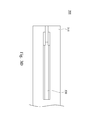
- the protecting slit 126 at least partially surrounds the optical measuring slit 124, and connects to the exit slit 140.
- the drainage slit 122 has an average width not larger than the optical measuring slit 124, and the protecting slit 126 has a width larger than the optical measuring slit 124.
- the dotted lines in Fig. 1A represent the junctions of different areas having different widths of the slit 120.
- the microcuvette 100 is sealed at the front, rear, left, and right sides, and the top and bottom sides of the microcuvette 100 are connected by the slit 120, the entry slit 130, and the exit slit 140.
- the positions and changes in width of the drainage slit 122, the optical measuring slit 124, and the protecting slit 126 can be seen through the exit slit 140 in the top view and the entry slit 130 in the bottom view.
- the entry slit 130 is connected to the drainage slit 122 and the protecting slit 126
- the exit slit 140 is connected to the drainage slit 122, the optical measuring slit 124, and the protecting slit 126.
- the width of the drainage slit 122 is equal to that of the optical measuring slit 124, but the width of the optical measuring slit 124 is smaller than that of the protecting slit 126.
- the change in width at the junction of the optical measuring slit 124 and the protecting slit 126 can be observed by the exit slit 140. Referring to Fig.
- the shape of the drainage slit across a longitudinal direction thereof is not limited in the present invention.
- the shape of the drainage slit across the longitudinal direction may be shown in a top view, a bottom view, or a cross-sectional view.
- the drainage slit has a variable width, and the width of the drainage slit described in the specification is an average width for that drainage slit.
- the shape of the drainage slit across the longitudinal direction is a rectangle as shown in Fig. 1D .
- the shape of the drainage slit across the longitudinal direction is a triangle.
- Fig. IE is another bottom view of the microcuvette 100 according to an embodiment of the present invention. The difference between the bottom views of Figs.
- the sample When introducing sample into the microcuvette 100, the sample enters the microcuvette 100 from the entry slit 130.
- the sample flows into the drainage slit 122 and the protecting slit 126, and fills the drainage slit 122 first because the capillary force of the drainage slit 122 is larger than that of the protecting slit 126.
- the sample gradually flows into and fills the optical measuring slit 124 and the protecting slit 126 through the connecting places between the drainage slit 122 and the optical measuring slit 124 and between the drainage slit 122 and the protecting slit 126.
- the sample enters the protecting slit 126 earlier than the optical measuring slit 124.
- the capillary force of the optical measuring slit 124 is larger than that of the protecting slit 126, the sample flows faster in the optical measuring slit 124, and fills the optical measuring slit 124 earlier than the protecting alit 126. Therefore, the air in inside the optical measuring slit 124 is pushed into the protecting slit 126, which is not fully filled with the sample.
- the width of the entry slit is smaller than that of the measuring slit, and the measuring slit has a uniform width. Therefore, bubbles exist within the measuring slit, and are difficult to remove.
- the optical measuring slit 124 further includes a transparent region 150 for measuring light passing through.
- the transparent region 150 has a circular shape, and located in the middle of the optical measuring slit 124.
- the transparent region 150 can be any shape, and be located in any portion of the optical measuring slit 124 as actual need.
- the optical measuring slit 124 has a transparency higher than other parts of the body 110.
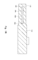
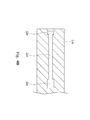
- Fig. 1B is a cross-sectional view through line A-A' of the microcuvette 100, which the change in width of the slit 120 can be observed by this cross-sectional view.
- this cross-sectional view shows the changes in width at the junctions of the drainage slit 122, the optical measuring slit 124, and the protecting slit 126.
- the change in width at the connecting place between the protecting slit 126 and the optical measuring slit 124 can be also observed by this cross-sectional view through line A-A' of the microcuvette 100. Therefore, the cross-sectional view through line A-A' of the microcuvette 100 at the part of the protecting slit 126 includes the inner walls of the protecting slit 126 and the inner walls of the optical measuring slit 124.
- the shape of the drainage slit across a longitudinal direction thereof is not limited in the present invention.
- the shape of the drainage slit across the longitudinal direction is a triangle.
- Fig. 1F which is another cross-sectional view through line A-A' of the microcuvette 100 according to an embodiment of the present invention.
- Fig. 1F shows the changes in width of the drainage slit 122 and at the junctions of the optical measuring slit 124 and the protecting slit 126.
- the change in width at the connecting place between the protecting slit 126 and the optical measuring slit 124 can be also observed by this cross-sectional view.
- the inner walls of the optical measuring slit 124 can be observed through the protecting slit 126 in Fig. 1F .
- the difference between the cross-sectional views of Figs. 1B and 1F is the shape of the drainage slit 122.
- the shape of the drainage slit 122 shown in Fig. 1B is a rectangle, and the shape of the drainage slit 122 shown in Fig. 1F is a triangle.
- the drainage slit 122 has an average width not larger than the optical measuring slit and a maximum width same as the width of the protecting slit 126. As long as the average width of the drainage slit 122 is not larger than the optical measuring slit, the sample can fill the drainage slit 122 first, and gradually fill the optical measuring slit 124 and the protecting slit 126.
- the width of the optical measuring slit 124 is smaller than that of the protecting slit 126, and thus the capillary force of the optical measuring slit 124 is larger.
- the speed of the sample flowing into the optical measuring slit 124 is faster than that of the protecting slit 126, and basically the optical measuring slit 124 is filled with the sample earlier than the protecting slit 126.
- the air inside the optical measuring slit 124 is pushed into the protecting slit 126, and exhausted to outside the microcuvette 100 through the exit slit 140. Therefore, it is not easy to produce bubbles in the optical measuring slit 124 during sampling.
- the entry slit 130 of the microcuvette 100 is cleaned by a wipe (not shown) to remove the sample left on the entry slit 130.
- the sample inside the slit 120 of the microcuvette 100 is drawn out by the capillary force of the wipe.
- the sample inside the protecting slit 126 is easier to be drawn, which protects the sample inside the optical measuring slit 124 from being affected by the wiping action.
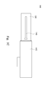
- Figs. 2A , 2C , and 2D are a front view, a top view, and a bottom view of a microcuvette 200 according to an embodiment of the present invention respectively.
- a grip of the microcuvette 200 is omitted, and only a body 210 of the microcuvette 200 is shown in the figures.
- the microcuvette 200 includes the body 210, and the body 210 includes a slit 220, an entry slit 230, and an exit slit 240 inside.
- the slit 220 includes a drainage slit 222, an optical measuring slit 224, and a protecting slit 226.
- the drainage slit 222 directly connects to the entry slit 230, the optical measuring slit 224, and the protecting slit 226, and the drainage slit 222 connects to the protecting slit 226 at two places.
- the protecting slit 226 surrounds the optical measuring slit 224 at the place that is not connected to the drainage slit 222, and connects to the exit slit 240.
- the drainage slit 222 has an average width not larger than the optical measuring slit 224, and the protecting slit 226 has a width larger than the optical measuring slit 224.
- the dotted lines in Fig. 2A represent the junctions of different areas having different widths of the slit 220. Referring to Figs.
- the microcuvette 200 is sealed at the front, rear, left, and right sides, and the top and bottom sides of the microcuvette 200 are connected by the slit 220, the entry slit 230, and the exit slit 240.
- the positions and changes in width of the drainage slit 222, the optical measuring slit 224, and the protecting slit 226 can be seen through the exit slit 240 in the top view and the entry slit 230 in the bottom view.
- the entry slit 230 is connected to the drainage slit 222 and the protecting slit 226, and the exit slit 240 is connected to the drainage slit 222 and the protecting slit 126. Furthermore, in this embodiment, the width of the drainage slit 222 is smaller than that of the optical measuring slit 224, and the width of the optical measuring slit 224 is smaller than that of the protecting slit 226. Referring to Fig.
- the change in width at the junction of the drainage slit 222 and the protecting slit 226 can be observed by the exit slit 240, and the changes in width at the connecting place between the protecting slit 226 and the optical measuring slit 224 can be observed through the protecting slit 226.
- the drainage slit 222 and the protecting slit 226 can be observed by the entry slit 230, and the changes in width at the connecting places between the protecting slit 226 and the drainage slit 222 and between the protecting slit 226 and the optical measuring slit 224 can be observed through the protecting slit 226.
- the inner walls of the drainage slit 222 and the optical measuring slit 224 can be observed through the protecting slit 226.
- the sample When introducing sample into the microcuvette 200, the sample enters the microcuvette 200 from the entry slit 230.
- the sample flows into the drainage slit 222 and the protecting slit 226, and fills the drainage slit 222 first because the capillary force of the drainage slit 222 is larger than that of the protecting slit 226.
- the sample gradually flows into and fills the optical measuring slit 224 and the protecting slit 226 through the connecting places between the drainage slit 222 and the optical measuring slit 224 and between the drainage slit 222 and the protecting slit 226.
- the optical measuring slit 224 further includes a transparent region 250 for measuring light passing through.
- the transparent region 250 has a circular shape, and located in the middle of the optical measuring slit 224.
- the transparent region 250 can be any shape, and be located in any portion of the optical measuring slit 224 as actual need.
- the optical measuring slit 224 has a transparency higher than other parts of the body 210.
- Fig. 2B is a cross-sectional view through line B-B' of the microcuvette 200, which the change in width of the slit 220 can be observed by this cross-sectional view.
- the grip of the microcuvette 200 is omitted, and only the body 210 of the microcuvette 200 is shown in Fig. 2B .
- this cross-sectional view shows the changes in width at the junctions of the drainage slit 222, the optical measuring slit 224, and the protecting slit 226.
- microcuvette 200 The differences between the microcuvette 200 and the microcuvette 100 are that the drainage slit 222 connects to the protecting slit 226 at two places, and the protecting slit 226 surrounds the optical measuring slit 224 at the place that is not connected to the drainage slit 222. These differences do not affect the function of each element in the embodiment, and thus the microcuvette 200 has the same functions and advantages as the microcuvette 100.
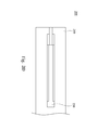
- Figs. 3A , 3C , and 3D are a front view, a top view, and a bottom view of a microcuvette 300 according to an embodiment of the present invention respectively.
- a grip of the microcuvette 300 is omitted, and only a body 310 of the microcuvette 300 is shown in the figures.
- the microcuvette 300 includes the body 310, and the body 310 includes a slit 320, an entry slit 330, and an exit slit 340 inside.
- the slit 320 includes a drainage slit 322, an optical measuring slit 324, and two protecting slits 326.
- the drainage slit 322 directly connects to the entry slit 330, the optical measuring slit 324, and the two protecting slits 226.
- the two protecting slits 326 at least partially surrounds the optical measuring slit 324.
- One protecting slit 326 connects to drainage slit 322, the optical measuring slit 324, and the entry slit 330, and another protecting slit 326 connects to drainage slit 322, the optical measuring slit 324, and the exit slit 340.
- the drainage slit 322 has an average width not larger than the optical measuring slit 324, and the protecting slits 326 have a width larger than the optical measuring slit 324.
- the microcuvette 300 is sealed at the front, rear, left, and right sides, and the top and bottom sides of the microcuvette 300 are connected by the slit 320, the entry slit 330, and the exit slit 340.
- the positions and changes in width of the drainage slit 322, the optical measuring slit 324, and the protecting slits 326 can be seen through the exit slit 340 in the top view and the entry slit 330 in the bottom view.
- the entry slit 330 is connected to the drainage slit 322 and one protecting slit 326
- the exit slit 340 is connected to the drainage slit 322 and another protecting slit 326.
- the width of the drainage slit 322 is smaller than that of the optical measuring slit 324
- the width of the optical measuring slit 324 is smaller than that of the protecting slits 326.
- the sample When introducing sample into the microcuvette 300, the sample enters the microcuvette 300 from the entry slit 330.
- the sample flows into the drainage slit 322 and the protecting slit 326, and fills the drainage slit 322 first because the capillary force of the drainage slit 322 is larger than that of the protecting slit 326.
- the sample gradually flows into and fills the optical measuring slit 324 and the protecting slits 326 through the connecting places between the drainage slit 322 and the optical measuring slit 324 and between the drainage slit 322 and the protecting slits 326.
- the optical measuring slit 324 further includes a transparent region 350 for measuring light passing through.
- the transparent region 350 has a circular shape, and located in the middle of the optical measuring slit 324.
- the transparent region 350 can be any shape, and be located in any portion of the optical measuring slit 324 as actual need.
- the optical measuring slit 324 has a transparency higher than other parts of the body 310.
- the cross-sectional view through line C-C' of the microcuvette 300 at the part of the protecting slit 326 includes the inner walls of the protecting slit 326 and the inner walls of the optical measuring slit 324.
- microcuvette 300 includes two protecting slits 326. This difference does not affect the function of each element in the embodiment, and thus the microcuvette 300 has the same functions and advantages as the microcuvette 100.
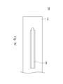
- Fig. 4A is a cross-sectional view through line A"-A'" of the microcuvette 100, which a portion of the drainage slit 122 close to the exit slit 140 is transformed into the protecting slit 126.
- Fig. 4A shows the cross-sectional view of the body 110 and the grip 112, and the changes in width of the slit 120 inside the body 110 can be observed.
- the width of the protecting slit 126 is larger than that of the optical measuring slit 124, the change in width at the junctions of the protecting slit 126 and the optical measuring slit 124 can be observed in Fig. 4A .
- Fig. 4B is a cross-sectional view through line B"-B'" of the microcuvette 200, which a portion of the drainage slit 222 close to the exit slit 240 is transformed into the protecting slit 226.
- Fig. 4B shows the cross-sectional view of the body 210, and the changes in width of the slit 220 inside the body 210 can be observed.
- the width of the protecting slit 226 is larger than that of the optical measuring slit 224, the change in width at the junction of the protecting slit 226 and the optical measuring slit 224 can be observed in Fig. 4B .
- the microcuvette of the present invention utilizes capillary action.
- Capillary force is inversely proportional to the slit width, and by adjusting the slit width of different areas, the capillary force of the drainage slit is not less than the optical measuring slit, and the capillary force of the protecting slit is less than the optical measuring slit.
- the average width of the drainage slit is 0.1-0.3 mm, preferably 0.15 mm.
- the width of the optical measuring slit is 0.1-0.3 mm, preferably 0.15 mm.
- the width of the protecting slit is 0.2-0.4 mm, preferably 0.3 mm.
- the bubbles will gradually flows into the protecting slit with the sample, and thereby the bubbles are pushed to the protecting slit, and exhausted to outside the microcuvette through the exit slit. Even if there are bubbles left in the slit of the microcuvette, the bubbles are left inside the protecting slit, not inside the optical measuring slit, which can prevent the bubbles from affecting measurement results. Furthermore, when sampling, the entry slit is located at a relatively bottom position, and the exit slit, which is opposite to the entry slit, is located at a relatively top position. Because of the physical characteristic of air, the bubbles are tend to move upward, and may be exhausted to outside the microcuvette through the exit slit.
- the entry slit is wiped to remove the sample left at the entry slit.
- the sample inside the measuring slit of current cuvette is prone to be drawn out through the entry slit because of the capillary action of the wipe. It is easy to produce bubbles in the measuring slit after sample being drawn out, and thus affects the measurement result.
- the protecting slit due to the location of the protecting slit, the sample inside the protecting slit is drawn out first while wiping the entry slit. Therefore, it can avoid sample being drawn out from the optical measuring slit, and affecting the measurement result.
- the microcuvette of the present invention may be made of any suitable materials for making cuvette, such as hydrophilic, optically transparent polystyrene (PS) and poly(methyl methacrylate) (PMMA).
- the microcuvette is an integrally molded structure.
- the mold for microcuvette molding includes foil, and a part of the foil corresponding for forming the transparent region in the optical measuring slit is polished to increase the transparency of the transparent region of the microcuvette made, which is beneficial for measuring light passing through.
- the structure of the microcuvette that the present invention proposed can reduce the probability of producing bubbles. Furthermore, adjusting the slit width of different areas by utilizing capillary action, the capillary force of the drainage slit is not less than the optical measuring slit, and the capillary force of the protecting slit is less than the optical measuring slit. Therefore, if bubbles are produced, the bubbles are pushed into the protecting slit, or exhausted to outside the microcuvette through the exit slit, which prevents the bubbles from affecting measurement results.
- Another function of setting the protecting slit is that when wiping the cuvette, the sample in the protecting slit is drawn out first, which can prevent the sample in the optical measuring slit from being drawn out, and prevent the measurement result from being affected.
- the structural design of the microcuvette can avoid generating interference factors at the optical measuring slit while molding into an integrally molded structure.
Landscapes
- Chemical & Material Sciences (AREA)
- Health & Medical Sciences (AREA)
- General Health & Medical Sciences (AREA)
- Analytical Chemistry (AREA)
- Life Sciences & Earth Sciences (AREA)
- Physics & Mathematics (AREA)
- Biochemistry (AREA)
- General Physics & Mathematics (AREA)
- Immunology (AREA)
- Pathology (AREA)
- Hematology (AREA)
- Clinical Laboratory Science (AREA)
- Chemical Kinetics & Catalysis (AREA)
- Dispersion Chemistry (AREA)
- Optical Measuring Cells (AREA)
Applications Claiming Priority (1)
| Application Number | Priority Date | Filing Date | Title |
|---|---|---|---|
| CN201310593603.2A CN104655568A (zh) | 2013-11-21 | 2013-11-21 | 微型比色皿 |
Publications (1)
| Publication Number | Publication Date |
|---|---|
| EP2876428A1 true EP2876428A1 (de) | 2015-05-27 |
Family
ID=51295540
Family Applications (1)
| Application Number | Title | Priority Date | Filing Date |
|---|---|---|---|
| EP14194089.0A Withdrawn EP2876428A1 (de) | 2013-11-21 | 2014-11-20 | Mikroküvette |
Country Status (4)
| Country | Link |
|---|---|
| US (1) | US20150138542A1 (de) |
| EP (1) | EP2876428A1 (de) |
| CN (1) | CN104655568A (de) |
| TW (2) | TWM478150U (de) |
Cited By (1)
| Publication number | Priority date | Publication date | Assignee | Title |
|---|---|---|---|---|
| EP3974809A1 (de) | 2020-09-29 | 2022-03-30 | Bioanalyt GmbH | Mikroküvette |
Families Citing this family (4)
| Publication number | Priority date | Publication date | Assignee | Title |
|---|---|---|---|---|
| USD870315S1 (en) * | 2017-11-09 | 2019-12-17 | Hemocue Ab | Cuvette |
| CN111912770A (zh) * | 2019-05-09 | 2020-11-10 | 磐创精准(北京)生物科技有限公司 | 一种手持式白细胞计数仪及白细胞计数方法 |
| CN111912771B (zh) * | 2019-05-09 | 2025-10-21 | 苏州中科苏净生物技术有限公司 | 一种免疫检测联合白细胞计数的同步检测装置及其检测方法 |
| CN111912766B (zh) * | 2019-05-09 | 2025-10-21 | 苏州中科苏净生物技术有限公司 | 免疫检测与细胞分析用组合检测卡及联合检测方法 |
Citations (3)
| Publication number | Priority date | Publication date | Assignee | Title |
|---|---|---|---|---|
| US5674457A (en) * | 1995-04-21 | 1997-10-07 | Hemocue Ab | Capillary microcuvette |
| US20060228258A1 (en) * | 2005-04-12 | 2006-10-12 | Chromedx Inc. | Blood collection and measurement apparatus |
| DE102006025477A1 (de) * | 2006-05-30 | 2007-12-06 | Ekf - Diagnostic Gmbh | Küvette |
Family Cites Families (3)
| Publication number | Priority date | Publication date | Assignee | Title |
|---|---|---|---|---|
| CN201262613Y (zh) * | 2008-08-28 | 2009-06-24 | 淄博前沿医疗器械有限公司 | 气液两用玻璃吸收光池 |
| CN201368842Y (zh) * | 2009-02-20 | 2009-12-23 | 程俊彪 | 毛细管流动比色皿 |
| CN203688436U (zh) * | 2013-11-21 | 2014-07-02 | 达尔生技股份有限公司 | 微型比色皿 |
-
2013
- 2013-11-21 CN CN201310593603.2A patent/CN104655568A/zh active Pending
- 2013-12-17 TW TW102223747U patent/TWM478150U/zh not_active IP Right Cessation
- 2013-12-17 TW TW102146490A patent/TWI494556B/zh not_active IP Right Cessation
-
2014
- 2014-11-20 EP EP14194089.0A patent/EP2876428A1/de not_active Withdrawn
- 2014-11-21 US US14/549,566 patent/US20150138542A1/en not_active Abandoned
Patent Citations (3)
| Publication number | Priority date | Publication date | Assignee | Title |
|---|---|---|---|---|
| US5674457A (en) * | 1995-04-21 | 1997-10-07 | Hemocue Ab | Capillary microcuvette |
| US20060228258A1 (en) * | 2005-04-12 | 2006-10-12 | Chromedx Inc. | Blood collection and measurement apparatus |
| DE102006025477A1 (de) * | 2006-05-30 | 2007-12-06 | Ekf - Diagnostic Gmbh | Küvette |
Cited By (2)
| Publication number | Priority date | Publication date | Assignee | Title |
|---|---|---|---|---|
| EP3974809A1 (de) | 2020-09-29 | 2022-03-30 | Bioanalyt GmbH | Mikroküvette |
| WO2022069536A1 (en) | 2020-09-29 | 2022-04-07 | Bioanalyt Gmbh | Microcuvette |
Also Published As
| Publication number | Publication date |
|---|---|
| TW201520530A (zh) | 2015-06-01 |
| US20150138542A1 (en) | 2015-05-21 |
| TWI494556B (zh) | 2015-08-01 |
| CN104655568A (zh) | 2015-05-27 |
| TWM478150U (zh) | 2014-05-11 |
Similar Documents
| Publication | Publication Date | Title |
|---|---|---|
| EP2876428A1 (de) | Mikroküvette | |
| KR102457612B1 (ko) | 유체 샘플을 수용하기 위한 디바이스 | |
| US11287365B2 (en) | Cuvette | |
| KR102260253B1 (ko) | 피펫 | |
| US8263025B2 (en) | Flow cell | |
| KR20150126960A (ko) | 소수성 내부 표면을 가지는 점적 챔버 | |
| KR101295534B1 (ko) | 큐베트와 이의 제작을 위한 성형 도구 및 제작 방법 | |
| CN108430639A (zh) | 流体收集装置及相关方法 | |
| WO2014153308A2 (en) | Pipette components useful for medical diagnostics | |
| JP2012078115A (ja) | 検査対象受体 | |
| CN103852576B (zh) | 用于液体分析的容器 | |
| Barillaro et al. | Integrated optofluidic microsystem based on vertical high-order one-dimensional silicon photonic crystals | |
| ITTO20000463A1 (it) | Dispensatore di agenti di lavaggio per una macchina di lavaggio domestica, in particolare una lavastoviglie. | |
| CN203688436U (zh) | 微型比色皿 | |
| CN204832046U (zh) | 用于检测杯的试纸条插片 | |
| US12306442B2 (en) | Structure including grating coupler with optofluidic grating channels | |
| WO2013155622A1 (en) | Device for optical examination of small samples | |
| CN201122149Y (zh) | 改进型比色杯 | |
| CN209656563U (zh) | 一种定容积液体分析容器 | |
| CN205175759U (zh) | 一种检测装置及其检测芯片 | |
| CN103760374B (zh) | 一种化学发光免疫分析检测用的反应杯 | |
| CN107664702B (zh) | 一种检测样本中被分析物的装置 | |
| CN114910332A (zh) | 一种切片样本染色装置和方法 | |
| JPWO2015198469A1 (ja) | ピペットチップ | |
| CN111912669A (zh) | 一种狭缝式液体取样检测腔室结构及取样方法 |
Legal Events
| Date | Code | Title | Description |
|---|---|---|---|
| PUAI | Public reference made under article 153(3) epc to a published international application that has entered the european phase |
Free format text: ORIGINAL CODE: 0009012 |
|
| 17P | Request for examination filed |
Effective date: 20141120 |
|
| AK | Designated contracting states |
Kind code of ref document: A1 Designated state(s): AL AT BE BG CH CY CZ DE DK EE ES FI FR GB GR HR HU IE IS IT LI LT LU LV MC MK MT NL NO PL PT RO RS SE SI SK SM TR |
|
| AX | Request for extension of the european patent |
Extension state: BA ME |
|
| STAA | Information on the status of an ep patent application or granted ep patent |
Free format text: STATUS: THE APPLICATION IS DEEMED TO BE WITHDRAWN |
|
| 18D | Application deemed to be withdrawn |
Effective date: 20151128 |