EP2876607B1 - Procédé et dispositif de production de données de forme - Google Patents
Procédé et dispositif de production de données de forme Download PDFInfo
- Publication number
- EP2876607B1 EP2876607B1 EP12881557.8A EP12881557A EP2876607B1 EP 2876607 B1 EP2876607 B1 EP 2876607B1 EP 12881557 A EP12881557 A EP 12881557A EP 2876607 B1 EP2876607 B1 EP 2876607B1
- Authority
- EP
- European Patent Office
- Prior art keywords
- shape
- input
- target
- input shape
- vertex
- Prior art date
- Legal status (The legal status is an assumption and is not a legal conclusion. Google has not performed a legal analysis and makes no representation as to the accuracy of the status listed.)
- Active
Links
Images












Classifications
-
- G—PHYSICS
- G06—COMPUTING OR CALCULATING; COUNTING
- G06T—IMAGE DATA PROCESSING OR GENERATION, IN GENERAL
- G06T19/00—Manipulating three-dimensional [3D] models or images for computer graphics
- G06T19/20—Editing of three-dimensional [3D] images, e.g. changing shapes or colours, aligning objects or positioning parts
-
- G—PHYSICS
- G06—COMPUTING OR CALCULATING; COUNTING
- G06T—IMAGE DATA PROCESSING OR GENERATION, IN GENERAL
- G06T15/00—Three-dimensional [3D] image rendering
-
- G—PHYSICS
- G06—COMPUTING OR CALCULATING; COUNTING
- G06T—IMAGE DATA PROCESSING OR GENERATION, IN GENERAL
- G06T3/00—Geometric image transformations in the plane of the image
- G06T3/10—Selection of transformation methods according to the characteristics of the input images
-
- G—PHYSICS
- G06—COMPUTING OR CALCULATING; COUNTING
- G06T—IMAGE DATA PROCESSING OR GENERATION, IN GENERAL
- G06T3/00—Geometric image transformations in the plane of the image
- G06T3/18—Image warping, e.g. rearranging pixels individually
-
- G—PHYSICS
- G06—COMPUTING OR CALCULATING; COUNTING
- G06T—IMAGE DATA PROCESSING OR GENERATION, IN GENERAL
- G06T7/00—Image analysis
- G06T7/0002—Inspection of images, e.g. flaw detection
- G06T7/0012—Biomedical image inspection
-
- G—PHYSICS
- G06—COMPUTING OR CALCULATING; COUNTING
- G06T—IMAGE DATA PROCESSING OR GENERATION, IN GENERAL
- G06T7/00—Image analysis
- G06T7/10—Segmentation; Edge detection
- G06T7/12—Edge-based segmentation
-
- G—PHYSICS
- G06—COMPUTING OR CALCULATING; COUNTING
- G06T—IMAGE DATA PROCESSING OR GENERATION, IN GENERAL
- G06T7/00—Image analysis
- G06T7/10—Segmentation; Edge detection
- G06T7/149—Segmentation; Edge detection involving deformable models, e.g. active contour models
-
- G—PHYSICS
- G06—COMPUTING OR CALCULATING; COUNTING
- G06T—IMAGE DATA PROCESSING OR GENERATION, IN GENERAL
- G06T2207/00—Indexing scheme for image analysis or image enhancement
- G06T2207/10—Image acquisition modality
- G06T2207/10072—Tomographic images
-
- G—PHYSICS
- G06—COMPUTING OR CALCULATING; COUNTING
- G06T—IMAGE DATA PROCESSING OR GENERATION, IN GENERAL
- G06T2207/00—Indexing scheme for image analysis or image enhancement
- G06T2207/30—Subject of image; Context of image processing
- G06T2207/30004—Biomedical image processing
- G06T2207/30048—Heart; Cardiac
-
- G—PHYSICS
- G06—COMPUTING OR CALCULATING; COUNTING
- G06T—IMAGE DATA PROCESSING OR GENERATION, IN GENERAL
- G06T2207/00—Indexing scheme for image analysis or image enhancement
- G06T2207/30—Subject of image; Context of image processing
- G06T2207/30004—Biomedical image processing
- G06T2207/30101—Blood vessel; Artery; Vein; Vascular
- G06T2207/30104—Vascular flow; Blood flow; Perfusion
-
- G—PHYSICS
- G06—COMPUTING OR CALCULATING; COUNTING
- G06T—IMAGE DATA PROCESSING OR GENERATION, IN GENERAL
- G06T2219/00—Indexing scheme for manipulating 3D models or images for computer graphics
- G06T2219/20—Indexing scheme for editing of 3D models
- G06T2219/2021—Shape modification
Definitions
- This technique relates to a shape data generation technique.
- the transformation is performed by correlating points in the standard shape with points in a target shape.
- the transformation is not appropriately performed when the points are not appropriately correlated.
- Patent Document 5 discloses a computer aided design method for producing an implant for a patient prior to operation comprising the steps of: generating data with a non-invasive 3D (3-dimensional) scan of the patient's defect site that digitally represents the area that will receive the implant; designing and validating an implant on a computer based on digital data generated from a volume image of the patient; and fabricating the implant based solely on the implant design data generated on computer.
- an object of this technique is to provide a new technique for generating highly accurate three-dimensional shape data.
- a shape data generation method relating to one aspect of this technique includes: (A) setting an input shape for a target shape that is a shape of a transformation target identified from image data, wherein the input shape has a simple shape that has a same topology as the target shape; (B) identifying first vertices that satisfy a predetermined condition among plural vertices of the input shape, wherein the predetermined condition includes a first condition that a normal line of a certain vertex of the plural vertices crosses with the target shape; (C) first transforming the input shape so that a first vertex is moved in a direction of a normal line of the first vertex by a first distance that is shorter than a distance up to the target shape; and (D) performing the identifying and the first transforming a predetermined number of times while changing the input shape after the first transforming as the input shape to be processed.
- FIG. 1 illustrates a functional block diagram of a shape data generation apparatus relating to a first embodiment of this technique.
- the shape data generation apparatus 100 has an image data storage unit 101, an input shape data storage unit 102, a transformation processing unit 103, a landmark data storage unit 104, a transformed shape data storage unit 105, an output processing unit 106, a display unit 107 and an input unit 108.
- the transformation processing unit 103 has an initial setting unit 1031, a landmark setting unit 1032, a transformation unit 1033 and a mesh processing unit 1034.
- Segment image data is stored in the image data storage unit 101.
- the segment image data is obtained by performing a processing for each portion to paint the inside of the boundary of the portion with a different brightness value for a Computed Tomography (CT) image of the heart of a specific patient or the like.
- CT Computed Tomography
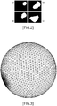
- FIG. 2 the three-dimensional data of the target shape, which is a shape that is a target of the transformation, is obtained.
- the images are accumulated in order of (a), (b), (c) and (d) from the bottom.
- the three-dimensional data of an input shape to be transformed is stored in the input shape data storage unit 102.
- the standard shape of the heart or the like is not used as the input shape, and a most uncharacteristic shape that has a topology similar to the shape to be represented is used.
- Such an input shape is a spherical shape in case of the three-dimensional closed surface, and is a discoid shape in case of the three-dimensional surface with an opening.
- the target shape is the three-dimensional closed surface will be explained. Therefore, the input shape is a sphere.
- a sphere whose surface is meshed is used as illustrated in FIG. 3 .
- the transformation processing unit 103 performs a processing to transform the input shape to the target shape. More specifically, the initial setting unit 1031 of the transformation processing unit 103 performs a processing to place the input shape for the target shape.
- the landmark setting unit 1032 performs a processing to set landmarks for the input shape or transformed input shape.
- the transformation unit 1033 performs a transformation processing by TPS Warp. As for the processing by the TPS Warp, Fred L. Bookstein, "Principal Warps: Thin-Plate Splines and the Decomposition of Deformations", IEEE TRANSACTIONS ON PATTERN ANALYSIS AND MACHINE INTELLIGENCE, VOL. 11, NO. 6, PP. 567-585, JUNE 1989 describes its details, therefore, the detailed explanation is omitted here.
- the mesh processing unit 1034 performs a remeshing processing according to the Delaunay triangle-division technique. Because the Delaunay triangle-division is well-known, the detailed explanation is omitted.
- the landmark data storage unit 104 stores data of the landmarks, which are set by the landmark setting unit 1032 and used in the transformation processing by the transformation unit 1033.
- the transformed shape data storage unit 105 stores shape data during the transformation processing and shape data after the completion of the transformation processing.
- the output processing unit 106 generates data to display, on the display unit 107, shape data after the completion of the transformation processing, which is stored in the transformed shape data storage unit 105, and outputs the generated data to the display unit 107.
- the input unit 108 accepts instructions or the like for the transformation processing unit 103 from a user, and outputs the instructions or the like to the transformation processing unit 103.
- the initial setting unit 1031 of the transformation processing unit 103 identifies the target shape from the image data stored in the image data storage unit 101, reads out data of the spherical input shape from the input shape data storage unit 102, expands or reduces the input shape so as to match the input shape with the target shape, and places the input shape so that the center of gravity of the input shape is identical to the center of gravity of the target shape ( FIG. 4 : step S1).
- the minimum hexahedron i.e. bounding box
- the average value of the lengths of the edges in x, y and z-axes of the bounding box is calculated.
- the sphere that is the input shape is expanded or reduced so that the expanded or reduced sphere is included in a cube whose edge has the length of that average.
- scale conversion with the expansion or reduction ratios that are different in three directions may be performed for the sphere so that the expanded or reduced sphere is included in the bounding box.
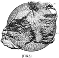
- FIG. 5 illustrates a state that a sphere 11 is placed for the target shape 10 that is the right atrium so that their centers of gravity are identical.
- the transformation processing unit 103 performs a transformation processing, and stores the shape data after the completion of the transformation processing in the transformed shape data storage unit 105 (step S3) .
- the transformation processing will be explained in detail later.
- the output processing unit 106 performs a processing to display the three-dimensional shape data after the completion of the transformation processing on the display unit 107 (step S5).
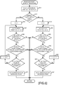
- m is a variable to count the number of vertices that have been processed.
- the transformation processing unit 103 increments the variable m by "1" (step S25), and the landmark setting unit 1032 of the transformation processing unit 103 performs a landmark setting processing (step S27).
- the landmark setting processing will be explained by using FIGs. 7 to 13 .
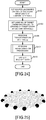
- the landmark setting unit 1032 randomly identifies one vertex v from data of the input shape or the input shape after the previous transformation ( FIG. 7 : step S41). Because there is no meaning for selection of the same vertex, an unselected vertex is selected while the value of t does not change, for example.
- the landmark setting unit 1032 respectively calculates a Euclid distance between each source landmark, which is stored in the landmark data storage unit 104, and the vertex v. In addition, the landmark setting unit 1032 determines whether or not the minimum distance among the Euclid distances between the vertex v and respective source landmarks is equal to or less than a threshold D (step S43) .
- the step S43 is a processing performed in order to locate the vertices v in the input shape or the input shape after the previous transformation, evenly as much as possible. It is determined at the step S43 whether or not a following expression is satisfied. min i d v v i ⁇ D
- d(v, v i ) represents a Euclid distance between a point v and a point v i .
- v i is a source landmark. However, because no source landmark is set initially, it is assumed that the Euclid distance exceeds the threshold D.
- step S43: Yes route When it is determined that the minimum distance among the Euclid distances between the vertex v and the respective source landmarks is equal to or less than the threshold D (step S43: Yes route), the processing returns to the calling-source processing. On the other hand, when it is determined that the minimum distance among the Euclid distances between the vertex v and the respective source landmarks is greater than the threshold D (step S43: No route), the landmark setting unit 1032 performs a boundary point search processing (step S45). The boundary point search processing will be explained by using FIGs. 8 to 13 .
- the landmark setting unit 1032 calculates a unit normal vector n(v) of the vertex v ( FIG. 8 : step S61).
- n(v) is a unit normal vector against a surface H at the vertex v ( ⁇ H).
- the unit normal vector is a normal vector having the length "1".
- H( ⁇ V) represents a shape surface of the input shape or the input shape after the previous transformation
- V( ⁇ R 3 ) represents a voxel space identified by the segment image data.
- R 3 represents a real number space.
- the value of the voxel in the segment image data is any one of two values "0" and "1", however, may be any value of values other than 0 and 1, or may be any value of two or more values.
- the voxel is a minimum cubic unit (i.e. regular grid) in the 3D expression of the digital data.
- the landmark setting unit 1032 determines whether or not the vertex v exists in the inside of the target shape (step S63). It is determined at the step S63 that a following expression is satisfied. f v > 0
- I is a brightness value of a voxel that includes a point p ( ⁇ V).
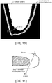
- the processing at the step S63 will be explained by using FIGs. 9 and 10 .
- FIG. 9 when the brightness value f(v) in the voxel space, which corresponds to the vertex v, is greater than 0, the vertex v exists within the target shape. Therefore, by performing setting to increment a coefficient k one-by-one in the processing of step S75, which will be explained later, the boundary point is searched for in a direction from the inside of the target shape to the outside.
- the brightness value f(v) in the voxel space, which corresponds to the vertex v becomes "0"
- the vertex v exists outside the target shape. Therefore, by performing setting to decrement the coefficient k one-by-one in the processing of step S89, which will be explained later, the boundary point is searched for in a direction from the outside of the target shape to the inside.
- step S63 Yes route
- the landmark setting unit 1032 sets a point for which it is determined whether it is the boundary point (hereinafter, referred to "search point") as follows: (step S67). v + kn v
- the landmark setting unit 1032 determines whether or not the search point exists within the voxel space identified from the segment image data (step S69). It is determined at the step S69 whether or not a following expression is satisfied. v + kn v ⁇ V
- step S69 No route
- the processing returns to the calling-source processing. This is because it is possible to determine that there is no cross point between the normal of the vertex v and the target shape, because the search point goes out of the voxel space.
- the landmark setting unit 1032 determines whether or not the search point passed through the shape before the transformation (i.e. input shape or input shape after the previous transformation) (step S71) . It is determined at the step S71 whether or not a following expression is satisfied.
- mapping g V -> R 3 is defined as follows:
- elements of the segment image data included in the voxel space V are correlated with the real number space R 3 .
- g p ⁇ n p if p ⁇ H 0 if p ⁇ H
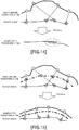
- step S71 will be explained by using FIGs. 11 and 12 .
- the search point passed through the shape before the transformation i.e. input shape or input shape after the previous transformation
- the search point passed through the shape before the transformation before the search point reaches the boundary point a case as illustrated in FIG. 11 and a case as illustrated in FIG. 12 are considered, for example.
- a case is considered that no boundary point exists in the search direction depending on the transforming degree against the target shape.
- the inner product between the normal vector for the vertex v and the normal vector for the search point is calculated, and when the inner product is less than "0" (i.e. an angle between the normal vectors is greater than 90 degrees), it is determined that the search point passed through the shape before the transformation.
- step S71: Yes route when it is determined that the search point passed through the shape before the transformation (step S71: Yes route), it is impossible to detect any boundary point, therefore, the processing returns to the calling-source processing.
- the landmark setting unit 1032 compares the brightness value in the voxel space, which corresponds to the search point, with the brightness value in the voxel space, which corresponds to the vertex v, and determines whether or not the brightness value is changed significantly, in other words, the brightness value is changed by a permissible value or more (step S73). It is determined at the step S73 whether or not a following expression is satisfied.
- step S73 when it is determined that the brightness value does not change significantly (step S73: No route), the landmark setting unit 1032 increments coefficient k by "1" (step S75), and the processing returns to the processing of the step S67.
- the landmark setting unit 1032 sets the search point as the boundary point (step S77).
- data of the search point for example, the value of k
- a memory device such as a main memory
- step S63 a processing performed when it is determined at the step S63 that the vertex v exists outside the target shape (step S63: No route) will be explained.
- This processing is different from the aforementioned processing only in the search direction. Therefore, the basic processing contents are as described above.
- a processing of step S79 is similar to the processing of the step S65
- a processing of step S81 is similar to the processing of the step S67
- a processing of step S83 is similar to the processing of the step S69
- a processing of step S85 is similar to the processing of step S71
- a processing of step S87 is similar to the step S73. Therefore, the detailed explanation for the processing of the steps S79 to S87 is omitted.
- step S89 the landmark setting unit 1032 decrements the coefficient k by "1" (step S89), and the processing returns to the step S81.
- the search point is moved one voxel in the normal direction from the outside of the target shape to the inside.
- step S91 is similar to the processing of the step S77.
- the landmark setting unit 1032 determines whether or not the boundary point was detected in the boundary point search processing (step S47). When it is determined that the boundary point was not detected (step S47: No route), the processing returns to the calling-source processing in order to process a next vertex.
- the landmark setting unit 1032 sets an inner dividing point of a segment connecting between the vertex v and the boundary point v + kn(v) as a target landmark (step S49) . More specifically, a following point is set as the target landmark. v + t T kn v
- the landmark setting unit 1032 sets the vertex v as the source landmark (step S51) .
- the source landmark data of a vertex identifier is stored in the landmark data storage unit 104, and as for the corresponding target landmark, coordinate data is stored in the landmark data storage unit 104.
- the coordinate data of the source landmark is read out and used from the input shape data storage unit 102 and by using an identifier of the source landmark in case where the input shape is processed, and is read out and used from the transformed shape data storage unit 105 in case where the input shape after the previous transformation is processed.
- the source landmark is used at the step S43, however, the source landmark that was set in the past is to be processed.
- a pair of the source landmark and the target landmark, which are set at the steps S49 and S51 is used only at the next execution of the step S31.
- the transformation processing unit 103 determines m ⁇ N holds for the variable m (step S29).
- N is a preset integer.
- the transformation unit 1033 of the transformation processing unit 103 performs the transformation processing by the TPS Warp according to data of the pair of the source landmark and the target landmark, which are set for the same t and stored in the landmark data storage unit 104, and stores the shape data after the transformation in the transformed shape data storage unit 105 (step S31).
- the source landmark is placed in the shape before the transformation
- the target landmark is placed at the cross point between the normal line at the source landmark and the target shape
- the transformation by the TPS Warp is performed.
- the normal lines cross each other, sometimes an unnatural shape, which is different from the target shape, is generated as the shape after the transformation.
- a target landmark i.e. circle with the cross hatching
- a point a point on a dashed line
- the source landmark i.e. circle with hatching by dots
- the mesh processing unit 1034 of the transformation processing unit 103 performs a remeshing processing for the shape data after the present transformation, which is stored in the transformed shape data storage unit 105, and stores processing results in the transformed shape data storage unit 105 (step S33).
- the remeshing processing is performed as a processing to subdivide mesh elements whose area exceeds a predetermined threshold and their surrounding mesh elements while repeating the transformation.
- the remeshing processing is performed as a processing to subdivide mesh elements whose area exceeds a predetermined threshold and their surrounding mesh elements while repeating the transformation.
- the Delaunay triangle division is well-known, however as an example, it will be explained simply.
- a new point a is added within a mesh element whose area exceeds a predetermined threshold.
- the point a is set without any relationship with the area, however, the new point a is set within the mesh element whose area exceeds the predetermined threshold.
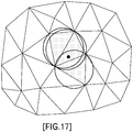
- a circumscribed circle of each mesh element is drawn, and a mesh element whose circumscribed circle contains the point a is identified.
- three mesh elements with hatching are identified.
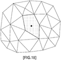
- a polygon is generated by these mesh elements ( FIG. 18 ), and the polygon is divided into triangles by vertices of this polygon and the point a ( FIG. 19 ).
- a triangle mesh is generated which includes triangles whose size is almost uniform.
- the transformation processing unit 103 determines whether or not t ⁇ T holds for the variable t (step S35). When it is determined that t ⁇ T holds (step S35: Yes route), the processing returns to the step S23 in order to further perform the transformation processing.
- step S35 No route
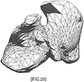
- the three-dimensional shape data as illustrated in FIG. 20 is obtained.
- the three-dimensional shape data whose sizes of the mesh elements are not uniform and that has low accuracy is obtained.
- the remeshing processing at the step S33 is performed, the three-dimensional shape as illustrated in FIG. 21 is obtained. It can be understood that the three-dimensional shape data with fine triangular elements and high accuracy is obtained.
- a three-dimensional curved surface that has an opening is assumed as a target shape. Although there are some unclear portions, a target shape as illustrated in FIG. 22 is assumed. A portion surrounded by a dotted line in this target shape is the opening.
- FIG. 23 a disciform input shape as illustrated in FIG. 23 is used, for example.
- FIG. 23 it seems that the meshing is not performed, however, it is assumed that the meshing has been performed.
- a shape data generation apparatus 100 illustrated in FIG. 1 performs a processing as illustrated in FIGs. 24 to 29 .
- the initial setting unit 1031 of the transformation processing unit 103 reads out data of the disciform input shape, which is stored in the input shape data storage unit 102, and sets source landmarks on an outer perimeter edge of the disc at uniform intervals ( FIG. 24 : step S101) .
- source landmarks are set on the outer perimeter of the disc.
- their vertex identifiers are stored in the landmark data storage unit 104. The source landmarks set at this step are handled as fixed points in the later processing.
- the initial setting unit 1031 identifies a target shape from the image data stored in the image data storage unit 101, and sets the same number of target landmarks as the number of source landmarks set for the input shape on an outer perimeter edge of an opening of the identified target shape at uniform intervals (step S103) .
- the target landmarks data of their vertex coordinates is stored in the landmark data storage unit 104.
- the same number of spherical target landmarks are set on the outer perimeter edge of the opening at uniform intervals .
- the initial setting unit 1031 causes the transformation unit 1033 to perform a transformation processing by TPS Warp so as to move the source landmarks to positions of the target landmarks, and stores the transformed shape data in the transformed shape data storage unit 105 (step S105) .
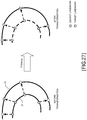
- FIG. 27 illustrates this transformation processing, schematically.
- the left of FIG. 27 illustrates a state before the transformation, and the source landmarks placed on the outer perimeter edge 21 of the input shape at uniform intervals are moved toward the target landmarks located on the outer perimeter edge 22 of the opening of the target shape at uniform intervals once to transform the input shape.
- the source landmarks are moved to the positions of the target landmarks, and other outer perimeter edge 21 of the input shape is transformed to be identical almost to the outer perimeter edge 22 of the opening of the target shape.
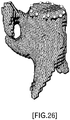
- FIGs. 25 and 26 a state schematically illustrated in FIG. 28 is obtained.
- portions painted on the upper surface correspond to the input shape.
- the transformation processing unit 103 performs a transformationprocessing (stepS107) .
- the basic flow of the processing follows a processing illustrated in FIGs. 6 to 8 .
- points different from the first embodiment are a point that the transformation processing has already been performed once, a point that the source landmarks has already been set, and a point the source landmarks are fixed points.
- the processing flow is different in a point that the Euclid distance is calculated even initially at the step S43.
- the processing flow is different in a point that the coordinate data of the fixed points is not changed in the transformation processing of the step S31.
- the output processing unit 106 performs a processing to display the transformed shape data stored in the transformed shape data storage unit 105 on the display unit 107 (step S109).
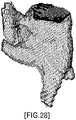
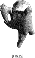
- FIG. 29 a processing result as illustrated in FIG. 29 is obtained.
- the shape data that is formed almost by uniform mesh elements is obtained.
- the atrium has more complex shape than the ventricle, because the ventricle is coupled to blood vessels such as the pulmonary vein and the vena cava. Then, as illustrated in FIG. 30 , an example will be explained that a processing is performed using, as an example of the target shape, a shape that the vena cava 31 extends from the right atrium.
- FIG. 31 A functional block diagram of a shape data generation apparatus 200 relating to this embodiment is illustrated in FIG. 31 .
- the shape data generation apparatus 200 has an image data storage unit 101b, an input shape data storage unit 102, a transformation processing unit 103b, a landmark data storage unit 104, a fixed point data storage unit 201, a transformed shape data storage unit 105, an output processing unit 106b, a display unit 107 and an input unit 108.
- Both first segment image data only for the right atrium and second segment image data for the right atrium and the blood vessels are stored in the image data storage unit 101b.
- the fixed point data storage unit 201 stores data of the fixed points set on the outer perimeter edge of the boundary portion between the transformed input shape obtained by performing the first transformation processing as described later and the blood vessels.
- the output processing unit 106b may output the transformed input shape obtained by performing the first transformation processing on the display unit 107 in response to an instruction from the transformation processing unit 103b.
- the transformation processing unit 103b has an initial setting unit 1031, a landmark setting unit 1032, a transformation unit 1033, a mesh processing unit 1034 and a second initial setting unit 1035.
- the second initial setting unit 1035 performs a setting processing that is performed before the second transformation processing.
- the initial setting unit 1031 of the transformation processing unit 103b identifies a target shape such as the right atrium without the blood vessels or the like from the first segment image data stored in the image data storage unit 101b, reads out data of the spherical input shape from the input shape data storage unit 102, expands or reduces the input shape so as to match the input shape with the target shape, and places the input shape so that the center of gravity of the input shape is identical to the center of gravity of the target shape ( FIG. 32 : step S201). This step is similar to the processing at the step S1 in FIG. 4 .
- the transformation processing unit 103b performs the first transformation processing, and stores the shape data after the completion of the transformation processing in the transformed shape data storage unit 105 (step S203) .
- the first transformation processing is similar to that at the step S3 in FIG. 4 , and the processing explained by using FIGs. 6 to 8 is performed.
- the second initial setting unit 1035 places the transformed input shape that is a processing result of the first transformation processing, which is stored in the transformed shape data storage unit 105, so that the transformed input shape is superimposed onto a second target shape including the right atrium and blood vessels, which are identified from the second segment image data stored in the image data storage unit 101b (step S205).
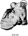
- the superimposed state is unclear, however, a state as illustrated in FIG. 33 is obtained.
- a portion surrounded by a circle represents a portion of the blood vessel, and this portion corresponds to a difference with the transformed input shape by the first transformation processing.
- the second initial setting unit 1035 sets, in the transformed input shape, fixed points on the outer perimeter edge of the boundary surface between the transformed input shape and the second target shape, and stores data of the fixed points in the fixed point data storage unit 201 (step S207) .
- data of vertex identifiers of the fixed points are stored in the fixed point data storage unit 201.
- FIG. 34 When a portion surrounded by a circle in FIG. 33 is expanded, a figure illustrated in FIG. 34 is obtained.
- a boundary surface 40 between the transformed input shape and the second target shape is identified.
- the fixed points illustrated by circles are set, for example, at uniform intervals, on the outer perimeter edge of this boundary surface 40.
- the fixed points may be set by the user via the input unit 108.
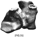
- FIG. 35 illustrates an example of the transformed input shape for which the fixed points are set.
- the fixed points are represented by spheres highlighted in FIG. 35 .
- the triangular mesh elements are formed on the internal surface, which is surrounded by the sphere.
- the transformation processing unit 103b performs a second transformation processing, and stores the processing result in the transformed shape data storage unit 105 (step S209) .
- this processing is similar to the transformation processing relating to the first embodiment.
- the output processing unit 106b performs a processing to display the shape data after the transformation, which is stored in the transformed shape data storage unit 105, on the display unit 107 (step S211).
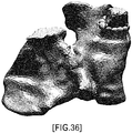
- FIG. 36 For example, a processing result as illustrated in FIG. 36 is obtained for the aforementioned example.
- the highlighted fixed points are still illustrated, however, actually the fixed points are not displayed.
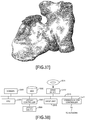
- the three-dimensional shape data as illustrated in FIG. 37 is obtained as data of the input shape transformed by the second transformation processing.
- the heart especially, the right atrium was explained as an example.
- the ventricle of the heart or other organs the similar processing can be applicable.
- the aforementioned shape data generation apparatuses 100 and 200 are computer devices as shown in FIG. 38 . That is, a memory 2501 (storage device), a CPU 2503 (processor), a hard disk drive (HDD) 2505, a display controller 2507 connected to a display device 2509, a drive device 2513 for a removable disk 2511, an input unit 2515, and a communication controller 2517 for connection with a network are connected through a bus 2519 as shown in FIG. 38 .
- An operating system (OS) and an application program for carrying out the foregoing processing in the embodiment, are stored in the HDD 2505, and when executed by the CPU 2503, they are read out from the HDD 2505 to the memory 2501.
- OS operating system
- an application program for carrying out the foregoing processing in the embodiment are stored in the HDD 2505, and when executed by the CPU 2503, they are read out from the HDD 2505 to the memory 2501.
- the CPU 2503 controls the display controller 2507, the communication controller 2517, and the drive device 2513, and causes them to perform necessary operations .
- intermediate processing data is stored in the memory 2501, and if necessary, it is stored in the HDD 2505.
- the application program to realize the aforementioned functions is stored in the computer-readable, non-transitory removable disk 2511 and distributed, and then it is installed into the HDD 2505 from the drive device 2513. It may be installed into the HDD 2505 via the network such as the Internet and the communication controller 2517.
- the hardware such as the CPU 2503 and the memory 2501, the OS and the necessary application programs systematically cooperate with each other, so that various functions as described above in details are realized.
- a shape data generation method relating to the embodiments includes: (A) setting an input shape for a target shape that is a shape of a transformation target identified from image data, wherein the input shape has a simple shape that has a same topology as the target shape; (B) identifying first vertices that satisfy a predetermined condition among plural vertices of the input shape, wherein the predetermined condition includes a first condition that a normal line of a certain vertex of the plural vertices crosses with the target shape; (C) first transforming the input shape so that a first vertex is moved in a direction of a normal line of the first vertex by a first distance that is shorter than a distance up to the target shape; and (D) performing the identifying and the first transforming a predetermined number of times while changing the input shape after the first transforming as the input shape to be processed.
- the first transforming may include performing a remeshing processing for a mesh element whose area exceeds a threshold and a surrounding mesh element among a plurality of mesh elements in the shape after the first transforming.
- the setting may include: when the target shape is a three-dimensional closed surface, reducing or expanding a spherical input shape in conformity with the target shape and placing the spherical input shape at a center of gravity of the target shape.
- the setting may include: when the target shape is a three-dimensional surface with an opening, second transforming a flat input shape in conformity with the opening.
- the first transforming may include: fixing an edge portion of the flat input shape that was transformed in conformity with the opening.
- this shape data generation method may further include: (E) placing a second input shape that is a shape obtained by the performing, for a second target shape that is identified from second image data and is a shape that an additional portion is attached to the targets shape, wherein fixed points that are not moved to an outer perimeter edge of a boundary surface with the additional portion are set in the second input shape; (F) second identifying second vertices that satisfy a second condition among plural vertices of the second input shape, wherein the second condition includes a condition that a normal line of a certain vertex of the plural vertices of the second input shape crosses with the second target shape; (G) second transforming the second input shape without the fixed points so that a second vertex is moved in a direction of a normal line of the second vertex by a second distance that is shorter than a distance up to the second target shape; and (H) performing the second identifying and the second transforming a second predetermined number of times while changing the second input shape after the second transforming as the second input shape to be processed.
- the aforementioned identifying or the second identifying may include: (X1) moving a vertex to be focused on in a direction of a normal line for the vertex to be focused on; first determining whether a point of a moving destination is included in a voxel space identified from the image data or the second image data; (X2) upon determining that the point of the moving destination is included in the voxel space, second determining whether the point of the moving destination passed through the input shape or the second input shape, based on an inner product of a normal vector for the vertex to be focused on and a normal vector for the point of the moving destination; (X3) upon determining that the point of the moving destination passed through the input shape, third determining whether a brightness value varied, by comparing a brightness value at the point of the moving destination with a brightness value at the vertex to be focused on; (X4) upon determining that the brightness value varied, fourth determining a condition is satisfied that the normal line for the vertex to be focused on crosses with the target shape or the second target
- a program causing a computer to execute the aforementioned processing, and such a program is stored in a computer readable storage medium or storage device such as a flexible disk, CD-ROM, DVD-ROM, magneto-optic disk, a semiconductor memory such as ROM (Read Only Memory), and hard disk.
- a storage device such as a main memory or the like.
Landscapes
- Engineering & Computer Science (AREA)
- General Physics & Mathematics (AREA)
- Theoretical Computer Science (AREA)
- Physics & Mathematics (AREA)
- Computer Vision & Pattern Recognition (AREA)
- Software Systems (AREA)
- Computer Graphics (AREA)
- General Engineering & Computer Science (AREA)
- Computer Hardware Design (AREA)
- Architecture (AREA)
- Health & Medical Sciences (AREA)
- General Health & Medical Sciences (AREA)
- Medical Informatics (AREA)
- Nuclear Medicine, Radiotherapy & Molecular Imaging (AREA)
- Radiology & Medical Imaging (AREA)
- Quality & Reliability (AREA)
- Processing Or Creating Images (AREA)
- Image Generation (AREA)
Claims (5)
- Procédé de génération de données de forme, comprenant les étapes consistant à :paramétrer une forme d'entrée pour une forme cible qui est une forme tridimensionnelle d'une cible de transformation identifiée à partir de données d'image, la forme d'entrée ayant une forme simple tridimensionnelle qui a la même topologie que la forme cible ;identifier, parmi une pluralité de sommets de la forme d'entrée, des premiers sommets dont la ligne normale croise la forme cible avant que la ligne normale croise la forme d'entrée ;transformer premièrement la forme d'entrée de sorte que chaque premier sommet soit déplacé dans une direction d'une ligne normale du premier sommet sur une première distance qui est inférieure à une distance allant jusqu'à la forme cible ; eteffectuer l'identification et la première transformation un nombre prédéterminé de fois tout en modifiant la forme d'entrée après la première transformation en tant que forme d'entrée à traiter,dans lequel le paramétrage comprend les étapes consistant à :lorsqu'il est détecté que la forme cible est une surface fermée tridimensionnelle, réduire ou agrandir une forme d'entrée sphérique qui est la forme d'entrée en conformité avec la forme cible et placer la forme d'entrée sphérique au niveau d'un centre de gravité de la forme cible ; etlorsqu'il est détecté que la forme cible est une surface tridimensionnelle avec une ouverture, transformer une forme d'entrée plate qui est l'entrée en conformité avec l'ouverture, et la première transformation comprend la fixation d'une partie de bord de la forme d'entrée plate qui a été transformée en conformité avec l'ouverture, etla première transformation comprend la réalisation d'un traitement de remaillage pour un élément de maillage dont la surface dépasse un seuil et un élément de maillage environnant parmi une pluralité d'éléments de maillage dans la forme d'entrée après la première transformation.
- Procédé de génération de données de forme selon la revendication 1, dans lequel le procédé comprend en outre les étapes consistant à :placer une seconde forme d'entrée qui est une forme obtenue par l'exécution, pour une seconde forme cible qui est identifiée à partir de secondes données d'image et est une forme tridimensionnelle, d'une partie supplémentaire qui est fixée à la forme cible, dans lequel des points fixes qui ne sont pas déplacés vers un bord de périmètre extérieur d'une surface limite avec la partie supplémentaire sont définis dans la seconde forme d'entrée ;identifier deuxièmement, parmi une pluralité de sommets de la seconde forme d'entrée, de seconds sommets qui satisfont à une seconde condition selon laquelle une ligne normale d'un certain sommet de la pluralité de sommets de la seconde forme d'entrée croise la seconde forme cible ;transformer deuxièmement la seconde forme d'entrée sans les points fixes de sorte qu'un second sommet est déplacé dans une direction d'une ligne normale du second sommet sur une seconde distance qui est inférieure à une distance allant jusqu'à la seconde forme cible ; eteffectuer la seconde identification et la seconde transformation un second nombre prédéterminé de fois tout en modifiant la seconde forme d'entrée après la seconde transformation en tant que seconde forme d'entrée à traiter.
- Procédé de génération de données de forme selon la revendication 1 ou la revendication 2, dans lequel l'identification ou la seconde identification comprend les étapes consistant à :déplacer un sommet devant faire l'objet d'une focalisation dans une direction d'une ligne normale pour le sommet devant faire l'objet d'une focalisation ;déterminer premièrement si un point d'une destination en mouvement est inclus ou non dans un espace de voxels identifié à partir des données d'image ou des secondes données d'image ;lorsqu'il est déterminé que le point de la destination en mouvement est inclus dans l'espace de voxels, déterminer deuxièmement si le point de la destination en mouvement est passé ou non à travers la forme d'entrée ou la seconde forme d'entrée, sur la base d'un produit interne d'un vecteur normal pour le sommet devant faire l'objet d'une focalisation et d'un vecteur normal pour le point de la destination en mouvement ;lorsqu'il est déterminé que le point de la destination en mouvement n'a pas traversé la forme d'entrée ou la seconde forme d'entrée, déterminer troisièmement si une valeur de luminosité a varié ou non, en comparant une valeur de luminosité au niveau du point de la destination en mouvement avec une valeur de luminosité au niveau du sommet devant faire l'objet d'une focalisation ;lorsqu'il est déterminé que la valeur de luminosité a varié, déterminer quatrièmement qu'une condition est satisfaite en ce sens que la ligne normale pour le sommet devant faire l'objet d'une focalisation croise la forme cible ou la seconde forme cible ;lorsqu'il est déterminé que le point de la destination en mouvement n'est pas inclus dans l'espace de voxels ou qu'il est déterminé que le point de la destination en mouvement a traversé la forme d'entrée ou la seconde forme d'entrée, déterminer cinquièmement qu'une condition n'est pas satisfaite en ce sens que la ligne normale pour le sommet devant faire l'objet d'une focalisation croise la forme d'entrée ou la seconde forme d'entrée ; etlorsqu'il est déterminé que la valeur de luminosité ne varie pas, effectuer à nouveau les première à cinquième déterminations pour le point de la destination en mouvement.
- Appareil de génération de données de forme, comprenant :une mémoire (2501) ; etun processeur (2503) configuré pour utiliser la mémoire et exécuter un processus, le processus comprenant les étapes consistant à :paramétrer une forme d'entrée pour une forme cible qui est une forme tridimensionnelle d'une cible de transformation identifiée à partir de données d'image, la forme d'entrée ayant une forme simple tridimensionnelle qui a la même topologie que la forme cible ;identifier, parmi une pluralité de sommets de la forme d'entrée, des premiers sommets dont la ligne normale croise la forme cible avant que la ligne normale croise la forme d'entrée ;transformer la forme d'entrée de sorte que chaque premier sommet soit déplacé dans une direction d'une ligne normale du premier sommet sur une première distance qui est inférieure à une distance allant jusqu'à la forme cible ; eteffectuer l'identification et la première transformation un nombre prédéterminé de fois tout en modifiant la forme d'entrée après la première transformation en tant que forme d'entrée à traiter,dans lequel le paramétrage comprend les étapes consistant à :lorsqu'il est détecté que la forme cible est une surface fermée tridimensionnelle, réduire ou agrandir une forme d'entrée sphérique qui est la forme d'entrée en conformité avec la forme cible et placer la forme d'entrée sphérique au niveau d'un centre de gravité de la forme cible, etlorsqu'il est détecté que la forme cible est une surface tridimensionnelle avec une ouverture, transformer une forme d'entrée plate qui est l'entrée en conformité avec l'ouverture, et la première transformation comprend la fixation d'une partie de bord de la forme d'entrée plate qui a été transformée en conformité avec l'ouverture, etla première transformation comprend la réalisation d'un traitement de remaillage pour un élément de maillage dont la surface dépasse un seuil et un élément de maillage environnant parmi une pluralité d'éléments de maillage dans la forme d'entrée après la première transformation.
- Programme informatique pour amener un ordinateur à exécuter le procédé de génération de données de forme défini dans l'une quelconque des revendications 1 à 3.
Applications Claiming Priority (1)
| Application Number | Priority Date | Filing Date | Title |
|---|---|---|---|
| PCT/JP2012/068634 WO2014016894A1 (fr) | 2012-07-23 | 2012-07-23 | Procédé et dispositif de production de données de forme |
Publications (3)
| Publication Number | Publication Date |
|---|---|
| EP2876607A1 EP2876607A1 (fr) | 2015-05-27 |
| EP2876607A4 EP2876607A4 (fr) | 2016-01-06 |
| EP2876607B1 true EP2876607B1 (fr) | 2019-07-31 |
Family
ID=49996731
Family Applications (1)
| Application Number | Title | Priority Date | Filing Date |
|---|---|---|---|
| EP12881557.8A Active EP2876607B1 (fr) | 2012-07-23 | 2012-07-23 | Procédé et dispositif de production de données de forme |
Country Status (4)
| Country | Link |
|---|---|
| US (1) | US9607423B2 (fr) |
| EP (1) | EP2876607B1 (fr) |
| JP (1) | JP5850380B2 (fr) |
| WO (1) | WO2014016894A1 (fr) |
Families Citing this family (6)
| Publication number | Priority date | Publication date | Assignee | Title |
|---|---|---|---|---|
| WO2015092842A1 (fr) * | 2013-12-16 | 2015-06-25 | 株式会社日立製作所 | Procédé et dispositif de production de données de maillage d'analyse |
| EP3180775B1 (fr) | 2014-11-18 | 2019-02-13 | St. Jude Medical, Cardiology Division, Inc. | Procédé et système pour générer un modèle de surface de pièce d'une structure géométrique |
| CN107209794B (zh) * | 2015-01-28 | 2022-02-08 | 皇家飞利浦有限公司 | 解剖结构的有限元建模 |
| JP6536169B2 (ja) * | 2015-05-21 | 2019-07-03 | カシオ計算機株式会社 | 画像処理装置、画像処理方法及びプログラム |
| EP3866107A1 (fr) * | 2020-02-14 | 2021-08-18 | Koninklijke Philips N.V. | Segmentation d'image basée sur un modèle |
| US12315081B2 (en) * | 2022-03-25 | 2025-05-27 | Sony Group Corporation | Mesh patch sub-division |
Family Cites Families (20)
| Publication number | Priority date | Publication date | Assignee | Title |
|---|---|---|---|---|
| JP2001034774A (ja) | 1999-07-21 | 2001-02-09 | Ricoh Co Ltd | 自由曲線の近似変換方法、装置及び記録媒体 |
| DE10111661A1 (de) | 2001-03-09 | 2002-09-12 | Philips Corp Intellectual Pty | Verfahren zum Segmentieren einer in einem Objekt enthaltenen dreidimensionalen Struktur, insbesondere für die medizinische Bildanalyse |
| WO2002073536A2 (fr) * | 2001-03-09 | 2002-09-19 | Koninklijke Philips Electronics N.V. | Segmentation d'image |
| US7221787B2 (en) * | 2002-12-10 | 2007-05-22 | Eastman Kodak Company | Method for automated analysis of digital chest radiographs |
| WO2004110309A2 (fr) * | 2003-06-11 | 2004-12-23 | Case Western Reserve University | Conception assistee par ordinateur d'implants du squelette |
| US7602965B2 (en) * | 2004-10-28 | 2009-10-13 | Siemens Medical Solutions Usa, Inc. | Object detection using cross-section analysis |
| US7620226B2 (en) * | 2004-10-28 | 2009-11-17 | Siemens Medical Solutions Usa, Inc. | Semi-local active contour for a faint region detection in knee CT images |
| JP2007098028A (ja) | 2005-10-07 | 2007-04-19 | Konica Minolta Medical & Graphic Inc | モデリング装置、モデリング方法、領域抽出装置、およびプログラム |
| JP2007159927A (ja) * | 2005-12-15 | 2007-06-28 | Konica Minolta Medical & Graphic Inc | モデリング装置、モデリング方法、領域抽出装置、領域抽出方法及びプログラム |
| US7557804B1 (en) * | 2006-03-06 | 2009-07-07 | Adobe Systems Inc. | Methods and apparatus for three-dimensional isographic navigation |
| JP4994737B2 (ja) * | 2006-07-27 | 2012-08-08 | オリンパスメディカルシステムズ株式会社 | 医療用画像処理装置及び医療用画像処理方法 |
| EP2081494B1 (fr) * | 2006-11-16 | 2018-07-11 | Vanderbilt University | Système et procédé de compensation de déformation d'organe |
| US8160345B2 (en) * | 2008-04-30 | 2012-04-17 | Otismed Corporation | System and method for image segmentation in generating computer models of a joint to undergo arthroplasty |
| US8108189B2 (en) * | 2008-03-25 | 2012-01-31 | Align Technologies, Inc. | Reconstruction of non-visible part of tooth |
| JP4931022B2 (ja) | 2008-09-04 | 2012-05-16 | 独立行政法人産業技術総合研究所 | 衣類状態推定方法及びプログラム |
| JP4806706B2 (ja) * | 2008-12-18 | 2011-11-02 | 株式会社日立製作所 | 解析モデルの変形方法および計算機 |
| JP5221436B2 (ja) * | 2009-04-02 | 2013-06-26 | トヨタ自動車株式会社 | 顔特徴点検出装置及びプログラム |
| JP5546230B2 (ja) * | 2009-12-10 | 2014-07-09 | キヤノン株式会社 | 情報処理装置、情報処理方法、及びプログラム |
| JP2011224143A (ja) * | 2010-04-20 | 2011-11-10 | Hitachi Aloka Medical Ltd | 超音波データ処理装置 |
| US20120253170A1 (en) * | 2011-03-29 | 2012-10-04 | Samsung Electronics Co., Ltd. | Method and apparatus for generating medical image of body organ by using 3-d model |
-
2012
- 2012-07-23 EP EP12881557.8A patent/EP2876607B1/fr active Active
- 2012-07-23 WO PCT/JP2012/068634 patent/WO2014016894A1/fr not_active Ceased
- 2012-07-23 JP JP2014526631A patent/JP5850380B2/ja not_active Expired - Fee Related
-
2015
- 2015-01-23 US US14/604,258 patent/US9607423B2/en not_active Expired - Fee Related
Non-Patent Citations (1)
| Title |
|---|
| None * |
Also Published As
| Publication number | Publication date |
|---|---|
| EP2876607A1 (fr) | 2015-05-27 |
| WO2014016894A1 (fr) | 2014-01-30 |
| JPWO2014016894A1 (ja) | 2016-07-07 |
| US20150131914A1 (en) | 2015-05-14 |
| EP2876607A4 (fr) | 2016-01-06 |
| JP5850380B2 (ja) | 2016-02-03 |
| US9607423B2 (en) | 2017-03-28 |
Similar Documents
| Publication | Publication Date | Title |
|---|---|---|
| EP2876607B1 (fr) | Procédé et dispositif de production de données de forme | |
| EP2779109B1 (fr) | Dispositif de traitement d'image, procédé de traitement d'image et structure de données de fichier d'image | |
| JP5120926B2 (ja) | 画像処理装置、画像処理方法およびプログラム | |
| CN100566661C (zh) | 图像诊断处理设备和图像诊断处理程序 | |
| JP4152648B2 (ja) | 対象物に含まれる三次元画像をセグメント化する方法 | |
| JP4512586B2 (ja) | 3次元データセットにおけるボリューム測定 | |
| JP2007523402A (ja) | 内部個別要素を用いるメッシュモデル | |
| JP5225999B2 (ja) | 結合された強度の投影 | |
| US10891787B2 (en) | Apparatus and method for creating biological model | |
| CN100585639C (zh) | 图像处理装置和图像处理方法 | |
| US10949698B2 (en) | Image processing apparatus, image processing system, image processing method, and storage medium | |
| JP2006055213A (ja) | 画像処理装置、及びプログラム | |
| US9836891B2 (en) | Shape data generation method and apparatus | |
| JP2007537811A (ja) | 結節の検出方法 | |
| JP6643821B2 (ja) | 画像処理装置 | |
| JP5721225B2 (ja) | 形状データ生成方法、プログラム及び装置 | |
| JP2004521425A (ja) | 対象の3次元表面上にマップされた3次元メッシュモデルの適合性評価のための画像処理方法 | |
| US9792729B2 (en) | System and method for context preserving maps of tubular structures | |
| CN107077718A (zh) | 在考虑待检查对象的解剖结构时重新格式化 | |
| JP5122650B2 (ja) | 経路近傍レンダリング | |
| EP2793192B1 (fr) | Procédé et appareil de traitement d'affichage | |
| JP6253962B2 (ja) | 情報処理装置及び方法 | |
| Marino et al. | Context preserving maps of tubular structures | |
| JP2019101966A (ja) | 画像生成装置および画像生成方法 | |
| JP2018005671A (ja) | 情報処理装置、シミュレータ結果表示方法、及びシミュレータ結果表示プログラム |
Legal Events
| Date | Code | Title | Description |
|---|---|---|---|
| PUAI | Public reference made under article 153(3) epc to a published international application that has entered the european phase |
Free format text: ORIGINAL CODE: 0009012 |
|
| 17P | Request for examination filed |
Effective date: 20150216 |
|
| AK | Designated contracting states |
Kind code of ref document: A1 Designated state(s): AL AT BE BG CH CY CZ DE DK EE ES FI FR GB GR HR HU IE IS IT LI LT LU LV MC MK MT NL NO PL PT RO RS SE SI SK SM TR |
|
| AX | Request for extension of the european patent |
Extension state: BA ME |
|
| DAX | Request for extension of the european patent (deleted) | ||
| RA4 | Supplementary search report drawn up and despatched (corrected) |
Effective date: 20151209 |
|
| RIC1 | Information provided on ipc code assigned before grant |
Ipc: G06T 19/00 20110101AFI20151203BHEP |
|
| STAA | Information on the status of an ep patent application or granted ep patent |
Free format text: STATUS: EXAMINATION IS IN PROGRESS |
|
| 17Q | First examination report despatched |
Effective date: 20180514 |
|
| GRAP | Despatch of communication of intention to grant a patent |
Free format text: ORIGINAL CODE: EPIDOSNIGR1 |
|
| STAA | Information on the status of an ep patent application or granted ep patent |
Free format text: STATUS: GRANT OF PATENT IS INTENDED |
|
| INTG | Intention to grant announced |
Effective date: 20190225 |
|
| GRAS | Grant fee paid |
Free format text: ORIGINAL CODE: EPIDOSNIGR3 |
|
| GRAA | (expected) grant |
Free format text: ORIGINAL CODE: 0009210 |
|
| STAA | Information on the status of an ep patent application or granted ep patent |
Free format text: STATUS: THE PATENT HAS BEEN GRANTED |
|
| AK | Designated contracting states |
Kind code of ref document: B1 Designated state(s): AL AT BE BG CH CY CZ DE DK EE ES FI FR GB GR HR HU IE IS IT LI LT LU LV MC MK MT NL NO PL PT RO RS SE SI SK SM TR |
|
| REG | Reference to a national code |
Ref country code: CH Ref legal event code: EP Ref country code: GB Ref legal event code: FG4D |
|
| REG | Reference to a national code |
Ref country code: DE Ref legal event code: R096 Ref document number: 602012062567 Country of ref document: DE |
|
| REG | Reference to a national code |
Ref country code: AT Ref legal event code: REF Ref document number: 1161727 Country of ref document: AT Kind code of ref document: T Effective date: 20190815 |
|
| REG | Reference to a national code |
Ref country code: IE Ref legal event code: FG4D |
|
| REG | Reference to a national code |
Ref country code: NL Ref legal event code: MP Effective date: 20190731 |
|
| REG | Reference to a national code |
Ref country code: LT Ref legal event code: MG4D |
|
| REG | Reference to a national code |
Ref country code: AT Ref legal event code: MK05 Ref document number: 1161727 Country of ref document: AT Kind code of ref document: T Effective date: 20190731 |
|
| PG25 | Lapsed in a contracting state [announced via postgrant information from national office to epo] |
Ref country code: FI Free format text: LAPSE BECAUSE OF FAILURE TO SUBMIT A TRANSLATION OF THE DESCRIPTION OR TO PAY THE FEE WITHIN THE PRESCRIBED TIME-LIMIT Effective date: 20190731 Ref country code: LT Free format text: LAPSE BECAUSE OF FAILURE TO SUBMIT A TRANSLATION OF THE DESCRIPTION OR TO PAY THE FEE WITHIN THE PRESCRIBED TIME-LIMIT Effective date: 20190731 Ref country code: HR Free format text: LAPSE BECAUSE OF FAILURE TO SUBMIT A TRANSLATION OF THE DESCRIPTION OR TO PAY THE FEE WITHIN THE PRESCRIBED TIME-LIMIT Effective date: 20190731 Ref country code: NO Free format text: LAPSE BECAUSE OF FAILURE TO SUBMIT A TRANSLATION OF THE DESCRIPTION OR TO PAY THE FEE WITHIN THE PRESCRIBED TIME-LIMIT Effective date: 20191031 Ref country code: NL Free format text: LAPSE BECAUSE OF FAILURE TO SUBMIT A TRANSLATION OF THE DESCRIPTION OR TO PAY THE FEE WITHIN THE PRESCRIBED TIME-LIMIT Effective date: 20190731 Ref country code: BG Free format text: LAPSE BECAUSE OF FAILURE TO SUBMIT A TRANSLATION OF THE DESCRIPTION OR TO PAY THE FEE WITHIN THE PRESCRIBED TIME-LIMIT Effective date: 20191031 Ref country code: SE Free format text: LAPSE BECAUSE OF FAILURE TO SUBMIT A TRANSLATION OF THE DESCRIPTION OR TO PAY THE FEE WITHIN THE PRESCRIBED TIME-LIMIT Effective date: 20190731 Ref country code: PT Free format text: LAPSE BECAUSE OF FAILURE TO SUBMIT A TRANSLATION OF THE DESCRIPTION OR TO PAY THE FEE WITHIN THE PRESCRIBED TIME-LIMIT Effective date: 20191202 Ref country code: AT Free format text: LAPSE BECAUSE OF FAILURE TO SUBMIT A TRANSLATION OF THE DESCRIPTION OR TO PAY THE FEE WITHIN THE PRESCRIBED TIME-LIMIT Effective date: 20190731 |
|
| PG25 | Lapsed in a contracting state [announced via postgrant information from national office to epo] |
Ref country code: ES Free format text: LAPSE BECAUSE OF FAILURE TO SUBMIT A TRANSLATION OF THE DESCRIPTION OR TO PAY THE FEE WITHIN THE PRESCRIBED TIME-LIMIT Effective date: 20190731 Ref country code: LV Free format text: LAPSE BECAUSE OF FAILURE TO SUBMIT A TRANSLATION OF THE DESCRIPTION OR TO PAY THE FEE WITHIN THE PRESCRIBED TIME-LIMIT Effective date: 20190731 Ref country code: GR Free format text: LAPSE BECAUSE OF FAILURE TO SUBMIT A TRANSLATION OF THE DESCRIPTION OR TO PAY THE FEE WITHIN THE PRESCRIBED TIME-LIMIT Effective date: 20191101 Ref country code: RS Free format text: LAPSE BECAUSE OF FAILURE TO SUBMIT A TRANSLATION OF THE DESCRIPTION OR TO PAY THE FEE WITHIN THE PRESCRIBED TIME-LIMIT Effective date: 20190731 Ref country code: AL Free format text: LAPSE BECAUSE OF FAILURE TO SUBMIT A TRANSLATION OF THE DESCRIPTION OR TO PAY THE FEE WITHIN THE PRESCRIBED TIME-LIMIT Effective date: 20190731 Ref country code: IS Free format text: LAPSE BECAUSE OF FAILURE TO SUBMIT A TRANSLATION OF THE DESCRIPTION OR TO PAY THE FEE WITHIN THE PRESCRIBED TIME-LIMIT Effective date: 20191130 |
|
| PG25 | Lapsed in a contracting state [announced via postgrant information from national office to epo] |
Ref country code: TR Free format text: LAPSE BECAUSE OF FAILURE TO SUBMIT A TRANSLATION OF THE DESCRIPTION OR TO PAY THE FEE WITHIN THE PRESCRIBED TIME-LIMIT Effective date: 20190731 |
|
| PG25 | Lapsed in a contracting state [announced via postgrant information from national office to epo] |
Ref country code: EE Free format text: LAPSE BECAUSE OF FAILURE TO SUBMIT A TRANSLATION OF THE DESCRIPTION OR TO PAY THE FEE WITHIN THE PRESCRIBED TIME-LIMIT Effective date: 20190731 Ref country code: PL Free format text: LAPSE BECAUSE OF FAILURE TO SUBMIT A TRANSLATION OF THE DESCRIPTION OR TO PAY THE FEE WITHIN THE PRESCRIBED TIME-LIMIT Effective date: 20190731 Ref country code: DK Free format text: LAPSE BECAUSE OF FAILURE TO SUBMIT A TRANSLATION OF THE DESCRIPTION OR TO PAY THE FEE WITHIN THE PRESCRIBED TIME-LIMIT Effective date: 20190731 Ref country code: RO Free format text: LAPSE BECAUSE OF FAILURE TO SUBMIT A TRANSLATION OF THE DESCRIPTION OR TO PAY THE FEE WITHIN THE PRESCRIBED TIME-LIMIT Effective date: 20190731 Ref country code: IT Free format text: LAPSE BECAUSE OF FAILURE TO SUBMIT A TRANSLATION OF THE DESCRIPTION OR TO PAY THE FEE WITHIN THE PRESCRIBED TIME-LIMIT Effective date: 20190731 |
|
| PG25 | Lapsed in a contracting state [announced via postgrant information from national office to epo] |
Ref country code: SK Free format text: LAPSE BECAUSE OF FAILURE TO SUBMIT A TRANSLATION OF THE DESCRIPTION OR TO PAY THE FEE WITHIN THE PRESCRIBED TIME-LIMIT Effective date: 20190731 Ref country code: SM Free format text: LAPSE BECAUSE OF FAILURE TO SUBMIT A TRANSLATION OF THE DESCRIPTION OR TO PAY THE FEE WITHIN THE PRESCRIBED TIME-LIMIT Effective date: 20190731 Ref country code: IS Free format text: LAPSE BECAUSE OF FAILURE TO SUBMIT A TRANSLATION OF THE DESCRIPTION OR TO PAY THE FEE WITHIN THE PRESCRIBED TIME-LIMIT Effective date: 20200224 Ref country code: CZ Free format text: LAPSE BECAUSE OF FAILURE TO SUBMIT A TRANSLATION OF THE DESCRIPTION OR TO PAY THE FEE WITHIN THE PRESCRIBED TIME-LIMIT Effective date: 20190731 |
|
| REG | Reference to a national code |
Ref country code: DE Ref legal event code: R097 Ref document number: 602012062567 Country of ref document: DE |
|
| PLBE | No opposition filed within time limit |
Free format text: ORIGINAL CODE: 0009261 |
|
| STAA | Information on the status of an ep patent application or granted ep patent |
Free format text: STATUS: NO OPPOSITION FILED WITHIN TIME LIMIT |
|
| PG2D | Information on lapse in contracting state deleted |
Ref country code: IS |
|
| PG25 | Lapsed in a contracting state [announced via postgrant information from national office to epo] |
Ref country code: IS Free format text: LAPSE BECAUSE OF FAILURE TO SUBMIT A TRANSLATION OF THE DESCRIPTION OR TO PAY THE FEE WITHIN THE PRESCRIBED TIME-LIMIT Effective date: 20191030 |
|
| 26N | No opposition filed |
Effective date: 20200603 |
|
| PG25 | Lapsed in a contracting state [announced via postgrant information from national office to epo] |
Ref country code: SI Free format text: LAPSE BECAUSE OF FAILURE TO SUBMIT A TRANSLATION OF THE DESCRIPTION OR TO PAY THE FEE WITHIN THE PRESCRIBED TIME-LIMIT Effective date: 20190731 |
|
| REG | Reference to a national code |
Ref country code: DE Ref legal event code: R082 Ref document number: 602012062567 Country of ref document: DE Representative=s name: HL KEMPNER PATENTANWAELTE, SOLICITORS (ENGLAND, DE Ref country code: DE Ref legal event code: R082 Ref document number: 602012062567 Country of ref document: DE Representative=s name: HL KEMPNER PATENTANWALT, RECHTSANWALT, SOLICIT, DE |
|
| PG25 | Lapsed in a contracting state [announced via postgrant information from national office to epo] |
Ref country code: MC Free format text: LAPSE BECAUSE OF FAILURE TO SUBMIT A TRANSLATION OF THE DESCRIPTION OR TO PAY THE FEE WITHIN THE PRESCRIBED TIME-LIMIT Effective date: 20190731 |
|
| REG | Reference to a national code |
Ref country code: CH Ref legal event code: PL |
|
| REG | Reference to a national code |
Ref country code: BE Ref legal event code: MM Effective date: 20200731 |
|
| PG25 | Lapsed in a contracting state [announced via postgrant information from national office to epo] |
Ref country code: LU Free format text: LAPSE BECAUSE OF NON-PAYMENT OF DUE FEES Effective date: 20200723 Ref country code: LI Free format text: LAPSE BECAUSE OF NON-PAYMENT OF DUE FEES Effective date: 20200731 Ref country code: CH Free format text: LAPSE BECAUSE OF NON-PAYMENT OF DUE FEES Effective date: 20200731 |
|
| PG25 | Lapsed in a contracting state [announced via postgrant information from national office to epo] |
Ref country code: BE Free format text: LAPSE BECAUSE OF NON-PAYMENT OF DUE FEES Effective date: 20200731 |
|
| PG25 | Lapsed in a contracting state [announced via postgrant information from national office to epo] |
Ref country code: IE Free format text: LAPSE BECAUSE OF NON-PAYMENT OF DUE FEES Effective date: 20200723 |
|
| PG25 | Lapsed in a contracting state [announced via postgrant information from national office to epo] |
Ref country code: MT Free format text: LAPSE BECAUSE OF FAILURE TO SUBMIT A TRANSLATION OF THE DESCRIPTION OR TO PAY THE FEE WITHIN THE PRESCRIBED TIME-LIMIT Effective date: 20190731 Ref country code: CY Free format text: LAPSE BECAUSE OF FAILURE TO SUBMIT A TRANSLATION OF THE DESCRIPTION OR TO PAY THE FEE WITHIN THE PRESCRIBED TIME-LIMIT Effective date: 20190731 |
|
| PG25 | Lapsed in a contracting state [announced via postgrant information from national office to epo] |
Ref country code: MK Free format text: LAPSE BECAUSE OF FAILURE TO SUBMIT A TRANSLATION OF THE DESCRIPTION OR TO PAY THE FEE WITHIN THE PRESCRIBED TIME-LIMIT Effective date: 20190731 |
|
| PGFP | Annual fee paid to national office [announced via postgrant information from national office to epo] |
Ref country code: FR Payment date: 20230620 Year of fee payment: 12 |
|
| PGFP | Annual fee paid to national office [announced via postgrant information from national office to epo] |
Ref country code: GB Payment date: 20230601 Year of fee payment: 12 |
|
| PGFP | Annual fee paid to national office [announced via postgrant information from national office to epo] |
Ref country code: DE Payment date: 20230531 Year of fee payment: 12 |
|
| REG | Reference to a national code |
Ref country code: DE Ref legal event code: R119 Ref document number: 602012062567 Country of ref document: DE |
|
| GBPC | Gb: european patent ceased through non-payment of renewal fee |
Effective date: 20240723 |
|
| PG25 | Lapsed in a contracting state [announced via postgrant information from national office to epo] |
Ref country code: DE Free format text: LAPSE BECAUSE OF NON-PAYMENT OF DUE FEES Effective date: 20250201 |
|
| PG25 | Lapsed in a contracting state [announced via postgrant information from national office to epo] |
Ref country code: FR Free format text: LAPSE BECAUSE OF NON-PAYMENT OF DUE FEES Effective date: 20240731 |
|
| PG25 | Lapsed in a contracting state [announced via postgrant information from national office to epo] |
Ref country code: GB Free format text: LAPSE BECAUSE OF NON-PAYMENT OF DUE FEES Effective date: 20240723 |