EP2876618A1 - Module de fin de ligne, contrôleur et procédé de commande pour système d'alarme - Google Patents
Module de fin de ligne, contrôleur et procédé de commande pour système d'alarme Download PDFInfo
- Publication number
- EP2876618A1 EP2876618A1 EP14192860.6A EP14192860A EP2876618A1 EP 2876618 A1 EP2876618 A1 EP 2876618A1 EP 14192860 A EP14192860 A EP 14192860A EP 2876618 A1 EP2876618 A1 EP 2876618A1
- Authority
- EP
- European Patent Office
- Prior art keywords
- line
- voltage
- alarm system
- module
- eol
- Prior art date
- Legal status (The legal status is an assumption and is not a legal conclusion. Google has not performed a legal analysis and makes no representation as to the accuracy of the status listed.)
- Withdrawn
Links
Images


Classifications
-
- G—PHYSICS
- G08—SIGNALLING
- G08B—SIGNALLING SYSTEMS, e.g. PERSONAL CALLING SYSTEMS; ORDER TELEGRAPHS; ALARM SYSTEMS
- G08B29/00—Checking or monitoring of signalling or alarm systems; Prevention or correction of operating errors, e.g. preventing unauthorised operation
- G08B29/12—Checking intermittently signalling or alarm systems
- G08B29/123—Checking intermittently signalling or alarm systems of line circuits
-
- G—PHYSICS
- G08—SIGNALLING
- G08B—SIGNALLING SYSTEMS, e.g. PERSONAL CALLING SYSTEMS; ORDER TELEGRAPHS; ALARM SYSTEMS
- G08B23/00—Alarms responsive to unspecified undesired or abnormal conditions
-
- G—PHYSICS
- G08—SIGNALLING
- G08B—SIGNALLING SYSTEMS, e.g. PERSONAL CALLING SYSTEMS; ORDER TELEGRAPHS; ALARM SYSTEMS
- G08B29/00—Checking or monitoring of signalling or alarm systems; Prevention or correction of operating errors, e.g. preventing unauthorised operation
- G08B29/02—Monitoring continuously signalling or alarm systems
- G08B29/06—Monitoring of the line circuits, e.g. signalling of line faults
Definitions
- the present invention relates to an End of Line (EOL) module for an alarm system, in particular to an EOL module which employs a resistor.
- EOL End of Line
- An alarm system is a product which is inextricably linked with production and life in society. It generally uses sound or light, etc. to remind or warn people to carry out some action, and is often applied in such fields as system failure, safety precautions, transport and communication, medical assistance, emergency rescue, sensing and detection. Examples are fire alarm systems and firedamp alarm systems, which are commonly seen in everyday life.
- An alarm system generally comprises a field side and a control side. Sensors in the field side are used for sensing whether a danger signal is present; for example, they may sense smoke or firedamp, etc. Having sensed the presence of a danger signal, a sensor will immediately send a signal to the control side. After receiving the signal, the control side supplies electrical energy to a warning device on the field side, so that said device issues an alarm in the form of sound or light, etc.
- the field side and control side are generally separated by a certain distance. For example, in the case of a fire alarm system, the control side is generally located in a central control room of the building, while the field side is located in various rooms inside the building.
- the control side and field side are generally connected by a transmission line such as a cable, for the transmission of signals and electrical energy between the two. This transmission line is also called a "field wire".
- the field wire is responsible for fulfilling the function of transmitting signals and electrical energy, so in the pre-alarm stage, the control side will continuously monitor the field wire to determine whether it has an open circuit or short circuit, in order to ensure that the alarm system can operate normally in an alarm stage.
- the field wire might also be in a "creeping open circuit (creeping open)” or “creeping short circuit (creeping short)” state.
- a creeping open circuit refers to a state in which the field wire has increased resistance, but has not yet developed a full open circuit.
- a creeping short circuit refers to a state in which the electrical isolation between two or more field wires has deteriorated, but a full short circuit has not yet occurred.
- full open circuits and full short circuits may be regarded as extreme special cases of creeping open circuits and creeping short circuits.
- Another example is that the structure of the field wires is easily destroyed by drilling work etc. in a building, with the cable being left in a loosely overlapping state, leading to a creeping open circuit or creeping short circuit state.
- Such a “creeping open” or “creeping short” state has a major impact on the operation of field wires.
- the impact is especially great when the field wire supplies electrical energy to a warning device, and may lead to failure of the alarm system.
- a warning device such as a loudspeaker needs a certain amount of electrical energy in order to start up; if there is a creeping open circuit in an alarm system line, then a larger voltage will be expended at the position of the creeping open circuit, so that the loudspeaker cannot obtain sufficient voltage, and cannot start up normally when an alarm needs to be raised. If there is a creeping short circuit in the alarm system, the loudspeaker will be unable to obtain sufficient current, and this will similarly lead to an alarm fault.
- it is necessary to detect the occurrence of a fault before a full short circuit or full open circuit occurs, i.e. during the creeping open circuit or creeping short circuit stage, in order to avoid the phenomenon of alarm failure.
- an End of Line (EOL) module is generally used in an alarm system to detect the occurrence of creeping open circuit and creeping short circuit faults.
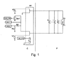
- Fig. 1 shows the basic structure of a fire alarm system with an EOL module, wherein the EOL module consists of a resistor, and is connected into the alarm system circuit by pins T1 and T2.
- the fire alarm system comprises a control side C and field side F.
- the EOL module is connected in parallel with loudspeakers h, i and j, and connected in series with resistors R2 and R3, and then after the series connection is supplied with a voltage V2.
- a control port MON_CTRL of a switch SW1 is used to control the voltage applied across the EOL module by controlling the switch SW1.
- SW1 When SW1 is conducting, the voltage across the EOL module is V2; when SW1 is open, the voltage across the EOL module is V2 - VREF1.
- a sensor When a sensor (not shown in Fig. 1 ) has sensed a fire emergency, it will send a signal to a control port DIR_CTRL of a double-pole double-throw switch N1 on the control side C, thereby inducing the double-pole double-throw switch N1 to switch over.
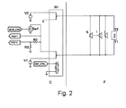
- the circuit in Fig. 1 will then change to the structure shown in Fig. 2 , so that the fire alarm system is in an alarm mode.
- the EOL module and loudspeakers h, i and j are supplied with a voltage by V1, the direction of current flow in EOL is from T1 to T2, and the loudspeakers issue a sound alarm.
- the resistance of the resistor in the EOL module is very large (generally, it must be no less than 1 k ⁇ ), to prevent current from bypassing the loudspeakers, and thereby prevent a situation in which the loudspeakers are unable to start up due to insufficient current.
- resistors with high resistances have a higher resistance tolerance.
- the resistance tolerance of a 1 k ⁇ resistor is generally in the range of ⁇ 1%, i.e. ⁇ 10 ⁇ .
- the present invention is intended to provide an EOL module for an alarm system, which is capable of precisely detecting a creeping open circuit or creeping short circuit fault when such a fault has just begun to occur.
- the present invention provides an EOL module for an alarm system, comprising: a first terminal and a second terminal; a switch unit and a resistor connected in series between the first and second terminals; a voltage polarity sensing circuit coupled between the first and second terminals, for sensing the polarity of a voltage between the first and second terminals, and when the sensed polarity indicates that the alarm system is in a monitoring mode, controlling the switch unit to conduct, and when the sensed polarity indicates that the alarm system is in an alarm mode, controlling the switch unit to turn off.
- the resistance of the resistor in such an EOL module can be set at a smaller value.
- the tiny fluctuation in resistance caused by creeping open circuits and creeping short circuits in the initial period of their occurrence can be detected, and will not be drowned in the resistance fluctuation range of the resistor.
- more precise checking of field wires is possible, and a creeping open circuit or creeping short circuit fault can be precisely detected when such a fault has just begun to occur.
- the voltage polarity sensing circuit comprises a first switching device and a control unit, while the switch unit comprises a second switching device, wherein the first and second switching devices are switched in a linked manner under the control of the control unit.
- the EOL module provided according to the present invention, wherein the control unit in the voltage polarity sensing circuit determines the voltage polarity sensed thereby according to the direction of current flow through the control unit.
- the EOL module provided according to the present invention, wherein the voltage polarity sensing circuit further comprises a first one-way conducting element and a second one-way conducting element, wherein the first switching device can connect one of the first and second one-way conducting elements in series with the control unit between the first and second terminals, and the respective directions of the first and second one-way conducting elements are opposite.
- the EOL module provided according to the present invention, wherein there is a first charge storage device connected in parallel with the first switching device between the first one-way conducting element and the control unit, and a second charge storage device connected in parallel with the first switching device between the second one-way conducting element and the control unit.
- the EOL module provided according to the present invention, wherein either one of the first charge storage device and second charge storage device is a capacitor.
- the EOL module provided according to the present invention wherein the first and second switching devices and the control unit are embodied as a latching relay.
- the EOL module provided according to the present invention wherein the latching relay is an electromagnetic latching relay, and the control unit is an excitation coil.
- the EOL module provided according to the present invention wherein the latching relay is a double-pole double-throw relay.
- the present invention further provides a control method for an alarm system, wherein one or more warning devices is/are connected in parallel on two lines led out from a control side of the alarm system, and an EOL module is connected at a far end of the two lines, the control method comprising: when the alarm system is in an alarm mode, applying a first voltage to the line, to drive an action of the warning device, while at the same time breaking the connection between the EOL module and the line; when the alarm system is in a monitoring mode, applying a second voltage to the line, so that the EOL module is coupled into a monitoring circuit comprising the line; when the alarm system is in the monitoring mode and the EOL module has been coupled into the monitoring circuit, applying a third voltage to the line, to detect whether a fault has occurred on the line; wherein the first voltage is of opposite polarity to the second and third voltages, and the third voltage is lower than the second voltage.
- the control method provided according to the present invention further comprising a step of initializing the EOL module, the initialization step comprising: applying the first voltage to the line, so that the EOL module is initialized by being disconnected from the line; and applying to the EOL module the third voltage which is lower than the first voltage, to monitor whether a first fault has occurred in the line connected to the alarm system.
- the first fault includes creeping short circuits and connection errors.
- the initialization step further comprising: applying the second voltage to the line, so that the EOL module is coupled into the monitoring circuit comprising the line; applying to the line the third voltage which is lower than the second voltage, to detect whether a second fault has occurred in the line of the alarm system.
- the second fault includes creeping open circuits.
- the initialization step further comprises: measuring the resistance of the line connected to the control side of the alarm system when the third voltage is applied to the line; and recording the measured resistance as a detection baseline for determining creeping open circuits and creeping short circuits.
- the present invention further provides a controller for an alarm system, wherein one or more warning devices are connected in parallel on two lines led out from the controller of the alarm system, and an EOL module is connected at a far end of the two lines, the controller comprising: an alarm unit, for applying a first voltage to the line when the alarm system is in an alarm mode, to drive an action of the warning device, while at the same time breaking the connection between the EOL module and the line; a monitoring mode switching unit, for applying a second voltage to the line when the alarm system is in a monitoring mode, so that the EOL module is coupled into a monitoring circuit comprising the line; a monitoring unit, for applying a third voltage to the line when the alarm system is in the monitoring mode and the EOL module has been coupled into the monitoring circuit, to detect whether a fault has occurred on the line; wherein the first voltage is of opposite polarity to the second and third voltages, and the third voltage is lower than the second voltage.
- the controller provided according to the present invention, further comprising an initialization unit, comprising: a reset subunit, for applying the first voltage to the line so that the EOL is initialized by being disconnected from the line; and a detection subunit, for applying the third voltage to the EOL module, to monitor whether a first fault has occurred in the line connected to the alarm system.
- the first fault includes creeping short circuits and connection errors.
- the initialization unit further comprises: a switching subunit, for applying the second voltage to the line, so that the EOL module is coupled into the monitoring circuit comprising the line; the detection subunit applies the third voltage to the line, to detect whether a second fault has occurred in the line of the alarm system.
- the initialization unit further comprises: a measurement subunit, for measuring the resistance of the line connected to the control side of the alarm system when the third voltage is applied to the line; and a recording subunit, for recording the measured resistance as a detection baseline for determining creeping open circuits and creeping short circuits.
- the controller provided according to the present invention, wherein the first fault includes creeping short circuits and connection errors, or the second fault includes creeping open circuits.
- the EOL module for an alarm system provided in the present invention is capable of precisely detecting a creeping open circuit or creeping short circuit fault when such a fault has just begun to occur, and need not be calibrated prior to installation.
- an EOL module for an alarm system with a basic circuit structure as shown in Fig. 3 .
- Pins T1 and T2 are for connecting into an alarm system circuit, such that the EOL module is connected in parallel with a loudspeaker or other warning device.
- a switch unit S11 and a resistor R1 are connected in series between pins T1 and T2.
- the EOL module also has a voltage polarity sensing circuit P, for sensing the polarity of a voltage between pins T1 and T2, and controlling the switching ON/OFF of the switch unit S11 according to the sensed polarity.
- V T2 of pin T2 When the alarm system is in a monitoring mode, a voltage V T2 of pin T2 is higher than a voltage V T1 of pin T1, the voltage polarity sensing circuit P makes the switch unit S11 conduct, such that the resistor R1 is connected to the field wire, for the purpose of measuring the resistance of the field wire, and thereby determining whether a creeping open circuit or creeping short circuit fault has occurred.
- V T2 When the alarm system is in an alarm mode, V T2 is lower than V T1 , in which case the voltage polarity sensing circuit P makes the switch unit S11 turn off, to break the connection between the resistor R1 and the field wire.
- the voltage polarity sensing circuit P is used to control the switch unit S11.
- the voltage polarity sensing circuit P causes the resistor R1 to be disconnected from the alarm system circuit.
- the resistor R1 will not cause current to bypass the alarm device (e.g. loudspeaker). Therefore the resistance of the resistor R1 in the EOL module of the present invention can be set at a smaller value than in single-resistor EOL modules in the prior art.
- the tiny fluctuation in resistance caused by creeping open circuits and creeping short circuits in the initial period of their occurrence can be detected, and will not be drowned in the resistance fluctuation range of the resistor R1.
- the EOL provided in the present invention is capable of realizing more precise checking of field wires, and precisely detecting a creeping open circuit or creeping short circuit fault when such a fault has just begun to occur.
- an EOL module for an alarm system is provided, with the basic circuit structure shown in Fig. 4 .
- Pins T1 and T2 are for connecting into an alarm system circuit, such that the EOL module is connected in parallel with a loudspeaker or other warning device.
- the EOL module provided in this embodiment employs a double-pole double-throw electromagnetic latching relay K11.
- the latching relay K11 comprises excitation coil pins 1 and 8, as well as a first set of switch pins 2, 3 and 4 and a second set of switch pins 5, 6 and 7.
- the first set of switch pins 2, 3 and 4 together form a first switching device, wherein pin 3 can switch between pins 2 and 4.
- the second set of switch pins 5, 6 and 7 together form a second switching device, wherein pin 6 can switch between pins 5 and 7, and the switching actions of pin 3 and pin 6 are linked.
- the various pins of the latching relay K11 are split into three parts in Fig. 4 .
- the latching relay K11 has a first position and a second position. In the first position (monitoring mode), pins 6 and 7 are connected, and pins 3 and 2 are connected (i.e. the position shown in Fig. 4 ). In the second position (alarm mode), pins 6 and 5 are connected, and pins 3 and 4 are connected.
- the latching relay K11 when the latching relay K11 is in the first position shown in Fig. 4 , if a voltage V k1 applied to excitation coil pin 1 is higher than a voltage V k8 applied to pin 8, and V k1 - V k8 is greater than a given action threshold V th (9 V in this embodiment), then the latching relay K11 will switch from the first position to the second position. If V k1 - V k8 is lower than the action threshold V th , the latching relay will maintain the current first position.
- the latching relay K11 when the latching relay K11 is in the second position, if the voltage V k8 applied to excitation coil pin 8 is higher than the voltage V k1 applied to pin 1, and V k8 - V k1 is greater than a given action threshold V th (9 V in this embodiment), then the latching relay K11 will switch from the second position to the first position. If V k8 - V k1 is lower than the action threshold V th , the latching relay K11 will maintain the current second position.
- one set of switch pins (5, 6 and 7) of the latching relay K11 controls when a resistor R11 is connected into the T1 - T2 loop.
- the excitation coil pins 1 and 8 and the other set of switch pins (2, 3 and 4) act as part of the voltage polarity sensing circuit P.
- the switching of positions of the latching relay is controlled by controlling the polarity and size of the voltage on the excitation coil pins, thereby enabling the resistor R11 to be disconnected from the alarm system circuit when the alarm system is in the alarm mode.
- diode V13 since diode V13 is in the reverse state, the voltage polarity sensing circuit P consumes no current in the alarm mode, and the excitation coil is no longer subject to a high voltage.
- Fig. 4 shows the circuit structure of the EOL module when the latching relay K11 is in the first position (i.e. R11 is connected to terminals T1 - T2 in the monitoring mode).
- a transient voltage suppressor (TVS) V16 is connected between pins T1 and T2, for protecting the EOL module from damage due to a surge between lines.
- Zener diodes V14 and V15 connected in series in opposite directions, are connected in parallel with excitation coil pins 1 and 8 of the latching relay K11, for the purpose of protecting the excitation coil of the latching relay K11 from damage due to overvoltage.
- V T2 When the alarm system is in the monitoring mode, V T2 is higher than V T1 . Since diode V12 is in the reverse direction, the excitation coil pins 1 and 8 of the latching relay K11 do not conduct. Conduction occurs between switch pins 6 and 7, so that the resistor R11 is connected between terminals T1 and T2, to monitor the state of the line. Moreover, since diode V12 is in the reverse direction state, the voltage polarity sensing circuit P consumes no current in the monitoring mode.
- V T2 is lower than V T1 , and V T1 - V T2 is greater than V K1 - V K8 , at which point diode V12 conducts, such that the voltage difference between excitation coil pins 1 and 8 of the latching relay K11 is greater than the action threshold V th , thereby making the latching relay K11 switch from the first position to the second position shown in Fig. 5 .
- switch pin 6 of the latching relay is connected to switch pin 5, while switch pin 3 is connected to switch pin 4.
- diode V13 is in the reverse direction, the excitation coil pins 1 and 8 of the latching relay K11 are no longer subject to a high voltage.
- An open circuit is formed between switch pins 6 and 7, and the open circuit position is latched, thereby disconnecting the resistor R11 from the alarm system circuit.
- capacitor C11 connected in parallel between switch pins 2 and 3 of the latching relay K11, and a capacitor C12 connected in parallel between switch pins 3 and 4.
- the function of capacitors C11 and C12 is to maintain the continuity of current in the excitation coil of the latching relay K11 while the latching relay K11 is switching between the first position and second position.
- R11 is for example 68 ⁇
- the excitation coil resistance of the latching relay is for example 1.44 k ⁇
- R13 is for example a 390 ⁇ current-limiting resistor.
- the diodes (V12, V13), resistor R13, capacitors (C11, C12) as well as the excitation coil and first switching device (including switch pins 2, 3 and 4) in the latching relay K11 are used to form the voltage polarity sensing circuit, for the purpose of controlling the second switching device (including switch pins 5, 6 and 7) of the latching relay K11, in order to disconnect resistor R11 from the alarm system circuit or connect it into this circuit.
- the voltage polarity sensing circuit can disconnect resistor R11 from the alarm system circuit.
- resistor R11 will not cause current to bypass the alarm device (e.g.
- the resistance of resistor R11 in the EOL module of this embodiment can be set at a smaller value than a single-resistor EOL module in the prior art.
- the tiny fluctuation in resistance caused by creeping open circuits and creeping short circuits in the initial period of their occurrence can be detected, and will not be drowned in the resistance tolerance range of resistor R11.
- the voltage polarity sensing circuit in this embodiment does not conduct in either the monitoring mode or the alarm mode, so consumes no electrical energy. Thus, it will neither affect the precision of field wire resistance measurement in the monitoring mode, nor affect the start-up of the alarm device (e.g. loudspeaker) in the alarm mode.
- a method for initializing the EOL module is also provided.
- Fig. 6 shows a timing diagram for the initialization method.
- the initialization method provided in this embodiment comprises the following steps:
- the step of field wire resistance detection and fault determination (S6) can be performed intermittently. As Fig. 6 shows, once the field wire resistance has been checked for a certain period of time, the step of field wire resistance detection and fault determination (S6) can be repeated after a standby interval S0. Before the step of field wire resistance detection and fault determination (S6) is repeated, the process of step 3) can also be performed once (S3), to ensure that the latching relay K11 is in the first position.
- the latching relay K11 will be switched to the second position, so that R11 is disconnected from the alarm system circuit, to prevent current from bypassing the loudspeaker.
- diode V13 is in the reverse state, the voltage polarity sensing circuit P consumes no current, and the excitation coil is no longer subject to a high voltage.
- the voltage between pins T1 and T2 may be continuous or pulsed, corresponding to continuous and intermittent sounding of the loudspeaker, respectively.
- steps S2, S3, S4, S5 and S6 in the initialization method are repeated (as shown in Fig. 6 ), so that the alarm system returns to the monitoring mode.
- the operating method described above may for example be implemented by a controller or control platform in the control side C in Fig. 1 .
- the controller for the alarm system is used to drive and control one or more warning devices h, i and j, which are connected in parallel on two lines led out from the alarm system controller, while an End of Line module EOL is connected at the far end of the two lines.
- Fig. 7 shows by way of example a structural block diagram of a controller for an alarm system according to an embodiment of the present invention.
- the controller comprises an alarm unit 710, for applying a first voltage (e.g. +28 V) to the line when the alarm system is in the alarm mode, to drive the action of the warning device, while at the same time breaking the connection between the EOL and the line; a monitoring mode switching unit 720, for applying a second voltage (e.g. -9 V) to the line when the alarm system is in the monitoring mode, so that the EOL is coupled into a monitoring circuit comprising the line; a monitoring unit 730, for applying a third voltage (e.g.
- the controller further comprises an initialization unit 740, for implementing an initialization operation.
- the initialization unit 740 comprises: a reset subunit 741, for applying the first voltage to the line so that the EOL is initialized by being disconnected from the line; and a detection subunit 742, for applying the third voltage to the EOL, to monitor whether a first fault has occurred in the line connected to the alarm system.
- the first fault includes creeping short circuits and connection errors.
- the initialization unit 740 may further comprise: a switching subunit 743, for applying the second voltage to the line, so that the EOL is coupled into the monitoring circuit comprising the line; at this point, the detection subunit 742 applies the third voltage to the line, to detect whether a second fault has occurred in the line of the alarm system.
- the second fault includes creeping open circuits.
- the initialization unit 740 further comprises: a measurement subunit 744, for measuring the resistance of the line connected to the control side of the alarm system when the third voltage is applied to the line; and a recording subunit 745, for recording the measured resistance as a detection baseline for determining creeping open circuits and creeping short circuits.
- the present invention was described using an electromagnetic latching relay as an example. In other embodiments according to the present invention, the present invention could be realized using other forms of relay with a latching function, or other forms of switching device with a latching function.
Landscapes
- Physics & Mathematics (AREA)
- General Physics & Mathematics (AREA)
- Engineering & Computer Science (AREA)
- Computer Security & Cryptography (AREA)
- Alarm Systems (AREA)
- Business, Economics & Management (AREA)
- Emergency Management (AREA)
- Fire Alarms (AREA)
Applications Claiming Priority (1)
| Application Number | Priority Date | Filing Date | Title |
|---|---|---|---|
| CN201310597392.XA CN104658203B (zh) | 2013-11-22 | 2013-11-22 | 用于报警系统的线末端模块、控制器及控制方法 |
Publications (1)
| Publication Number | Publication Date |
|---|---|
| EP2876618A1 true EP2876618A1 (fr) | 2015-05-27 |
Family
ID=51947150
Family Applications (1)
| Application Number | Title | Priority Date | Filing Date |
|---|---|---|---|
| EP14192860.6A Withdrawn EP2876618A1 (fr) | 2013-11-22 | 2014-11-12 | Module de fin de ligne, contrôleur et procédé de commande pour système d'alarme |
Country Status (3)
| Country | Link |
|---|---|
| EP (1) | EP2876618A1 (fr) |
| CN (1) | CN104658203B (fr) |
| RU (1) | RU2014146983A (fr) |
Cited By (1)
| Publication number | Priority date | Publication date | Assignee | Title |
|---|---|---|---|---|
| JP2020145580A (ja) * | 2019-03-06 | 2020-09-10 | 三協電子工業株式会社 | 音声緊急情報報知装置 |
Citations (2)
| Publication number | Priority date | Publication date | Assignee | Title |
|---|---|---|---|---|
| EP1777671A1 (fr) * | 2005-10-19 | 2007-04-25 | Honeywell International, Inc. | Surveiller le câblage d'un système d'alarme |
| FR2932917A1 (fr) * | 2008-06-23 | 2009-12-25 | Legrand France | Installation de securite a auto-diagnostic perfectionne. |
Family Cites Families (6)
| Publication number | Priority date | Publication date | Assignee | Title |
|---|---|---|---|---|
| US3500394A (en) * | 1966-12-23 | 1970-03-10 | Honeywell Inc | Control apparatus |
| US4191946A (en) * | 1977-10-20 | 1980-03-04 | Gonzalez Raymond J | Warning apparatus with a line integrity supervisory circuit |
| US4224538A (en) * | 1978-09-15 | 1980-09-23 | Firetek Corporation | Series supervision/parallel actuation device |
| GB2320121A (en) * | 1996-12-07 | 1998-06-10 | Menvier | Alarm system |
| EP1855261B2 (fr) * | 2006-05-11 | 2014-06-11 | Siemens Aktiengesellschaft | Procédé et dispositif destinés à la surveillance de perturbations sur une ligne d'avertissement d'une installation d'avertissement d'incendie |
| CN102236955A (zh) * | 2010-04-21 | 2011-11-09 | 任文华 | 报警电路装置 |
-
2013
- 2013-11-22 CN CN201310597392.XA patent/CN104658203B/zh not_active Expired - Fee Related
-
2014
- 2014-11-12 EP EP14192860.6A patent/EP2876618A1/fr not_active Withdrawn
- 2014-11-21 RU RU2014146983A patent/RU2014146983A/ru not_active Application Discontinuation
Patent Citations (2)
| Publication number | Priority date | Publication date | Assignee | Title |
|---|---|---|---|---|
| EP1777671A1 (fr) * | 2005-10-19 | 2007-04-25 | Honeywell International, Inc. | Surveiller le câblage d'un système d'alarme |
| FR2932917A1 (fr) * | 2008-06-23 | 2009-12-25 | Legrand France | Installation de securite a auto-diagnostic perfectionne. |
Cited By (1)
| Publication number | Priority date | Publication date | Assignee | Title |
|---|---|---|---|---|
| JP2020145580A (ja) * | 2019-03-06 | 2020-09-10 | 三協電子工業株式会社 | 音声緊急情報報知装置 |
Also Published As
| Publication number | Publication date |
|---|---|
| RU2014146983A (ru) | 2016-06-10 |
| CN104658203B (zh) | 2017-08-25 |
| CN104658203A (zh) | 2015-05-27 |
Similar Documents
| Publication | Publication Date | Title |
|---|---|---|
| RU2618793C1 (ru) | Способ и устройство для измерения сопротивления линии управляющих линий в системах аварийной сигнализации и управления | |
| EP2669693B1 (fr) | Dispositif et système de détection de défaut de câble à fonctionnement en parallèle | |
| JP5563092B2 (ja) | バッテリと制御装置からなる構造 | |
| KR100816984B1 (ko) | 배전반 화재감시제어기 | |
| US10998683B2 (en) | Connector protection method and system | |
| CN107255782A (zh) | 一种高压互锁检测电路及互锁信号检测方法 | |
| CN105359367A (zh) | 电池过充电防止装置 | |
| US20090212937A1 (en) | Active line termination module | |
| CN109490771B (zh) | 一种继电器检测方法以及继电器检测装置 | |
| US6567001B1 (en) | Fire control panel monitoring for degradation of wiring integrity during alarm state | |
| CN104897967B (zh) | 火警系统的现场连线检测装置及方法 | |
| CN110622015B (zh) | 用于对控制器供电的装置和用于监控供电的方法 | |
| EP3799003B1 (fr) | Circuit de détection de fumée et panneau d'affichage l'utilisant | |
| JP7164960B2 (ja) | スイッチの断線検出装置 | |
| CN104658203B (zh) | 用于报警系统的线末端模块、控制器及控制方法 | |
| CN113056679A (zh) | 用于开关设备的安全关键的触发装置的接触监控装置 | |
| CN112313828A (zh) | 用于电能的存储单元、及其监控方法和车辆 | |
| CN105659427A (zh) | 一种利用电池传感器以检测多个电极的锁固状态检测装置 | |
| CN207249077U (zh) | 一种节能消防应急电源状态检测装置 | |
| CN119363512B (zh) | 寻址转非寻址装置以及报警系统 | |
| CN220983885U (zh) | 一种计算机主板防护系统及计算机设备 | |
| CN205450227U (zh) | 高可靠远程消防设备电源监控系统 | |
| CN203260867U (zh) | 一种带状态显示的usb联接线 | |
| CN110505741A (zh) | 一种检测航行信号灯状态的方法及装置 | |
| EP3404928A1 (fr) | Dispositif électronique amélioré pour contrôler des capteurs d'incendie. |
Legal Events
| Date | Code | Title | Description |
|---|---|---|---|
| PUAI | Public reference made under article 153(3) epc to a published international application that has entered the european phase |
Free format text: ORIGINAL CODE: 0009012 |
|
| 17P | Request for examination filed |
Effective date: 20141112 |
|
| AK | Designated contracting states |
Kind code of ref document: A1 Designated state(s): AL AT BE BG CH CY CZ DE DK EE ES FI FR GB GR HR HU IE IS IT LI LT LU LV MC MK MT NL NO PL PT RO RS SE SI SK SM TR |
|
| AX | Request for extension of the european patent |
Extension state: BA ME |
|
| STAA | Information on the status of an ep patent application or granted ep patent |
Free format text: STATUS: THE APPLICATION IS DEEMED TO BE WITHDRAWN |
|
| 18D | Application deemed to be withdrawn |
Effective date: 20151128 |