EP2876705A2 - Stromschiene für montierte Batterie - Google Patents
Stromschiene für montierte Batterie Download PDFInfo
- Publication number
- EP2876705A2 EP2876705A2 EP14190864.0A EP14190864A EP2876705A2 EP 2876705 A2 EP2876705 A2 EP 2876705A2 EP 14190864 A EP14190864 A EP 14190864A EP 2876705 A2 EP2876705 A2 EP 2876705A2
- Authority
- EP
- European Patent Office
- Prior art keywords
- electrode terminal
- portions
- busbar
- negative electrode
- positive electrode
- Prior art date
- Legal status (The legal status is an assumption and is not a legal conclusion. Google has not performed a legal analysis and makes no representation as to the accuracy of the status listed.)
- Withdrawn
Links
Images


Classifications
-
- H—ELECTRICITY
- H01—ELECTRIC ELEMENTS
- H01R—ELECTRICALLY-CONDUCTIVE CONNECTIONS; STRUCTURAL ASSOCIATIONS OF A PLURALITY OF MUTUALLY-INSULATED ELECTRICAL CONNECTING ELEMENTS; COUPLING DEVICES; CURRENT COLLECTORS
- H01R11/00—Individual connecting elements providing two or more spaced connecting locations for conductive members which are, or may be, thereby interconnected, e.g. end pieces for wires or cables supported by the wire or cable and having means for facilitating electrical connection to some other wire, terminal, or conductive member, blocks of binding posts
- H01R11/11—End pieces or tapping pieces for wires, supported by the wire and for facilitating electrical connection to some other wire, terminal or conductive member
- H01R11/28—End pieces consisting of a ferrule or sleeve
- H01R11/281—End pieces consisting of a ferrule or sleeve for connections to batteries
- H01R11/288—Interconnections between batteries
-
- H—ELECTRICITY
- H01—ELECTRIC ELEMENTS
- H01M—PROCESSES OR MEANS, e.g. BATTERIES, FOR THE DIRECT CONVERSION OF CHEMICAL ENERGY INTO ELECTRICAL ENERGY
- H01M50/00—Constructional details or processes of manufacture of the non-active parts of electrochemical cells other than fuel cells, e.g. hybrid cells
- H01M50/50—Current conducting connections for cells or batteries
- H01M50/502—Interconnectors for connecting terminals of adjacent batteries; Interconnectors for connecting cells outside a battery casing
- H01M50/503—Interconnectors for connecting terminals of adjacent batteries; Interconnectors for connecting cells outside a battery casing characterised by the shape of the interconnectors
-
- H—ELECTRICITY
- H01—ELECTRIC ELEMENTS
- H01M—PROCESSES OR MEANS, e.g. BATTERIES, FOR THE DIRECT CONVERSION OF CHEMICAL ENERGY INTO ELECTRICAL ENERGY
- H01M50/00—Constructional details or processes of manufacture of the non-active parts of electrochemical cells other than fuel cells, e.g. hybrid cells
- H01M50/50—Current conducting connections for cells or batteries
- H01M50/502—Interconnectors for connecting terminals of adjacent batteries; Interconnectors for connecting cells outside a battery casing
- H01M50/505—Interconnectors for connecting terminals of adjacent batteries; Interconnectors for connecting cells outside a battery casing comprising a single busbar
-
- H—ELECTRICITY
- H01—ELECTRIC ELEMENTS
- H01M—PROCESSES OR MEANS, e.g. BATTERIES, FOR THE DIRECT CONVERSION OF CHEMICAL ENERGY INTO ELECTRICAL ENERGY
- H01M50/00—Constructional details or processes of manufacture of the non-active parts of electrochemical cells other than fuel cells, e.g. hybrid cells
- H01M50/50—Current conducting connections for cells or batteries
- H01M50/502—Interconnectors for connecting terminals of adjacent batteries; Interconnectors for connecting cells outside a battery casing
- H01M50/514—Methods for interconnecting adjacent batteries or cells
- H01M50/516—Methods for interconnecting adjacent batteries or cells by welding, soldering or brazing
-
- H—ELECTRICITY
- H01—ELECTRIC ELEMENTS
- H01M—PROCESSES OR MEANS, e.g. BATTERIES, FOR THE DIRECT CONVERSION OF CHEMICAL ENERGY INTO ELECTRICAL ENERGY
- H01M50/00—Constructional details or processes of manufacture of the non-active parts of electrochemical cells other than fuel cells, e.g. hybrid cells
- H01M50/50—Current conducting connections for cells or batteries
- H01M50/502—Interconnectors for connecting terminals of adjacent batteries; Interconnectors for connecting cells outside a battery casing
- H01M50/521—Interconnectors for connecting terminals of adjacent batteries; Interconnectors for connecting cells outside a battery casing characterised by the material
- H01M50/522—Inorganic material
-
- H—ELECTRICITY
- H01—ELECTRIC ELEMENTS
- H01M—PROCESSES OR MEANS, e.g. BATTERIES, FOR THE DIRECT CONVERSION OF CHEMICAL ENERGY INTO ELECTRICAL ENERGY
- H01M50/00—Constructional details or processes of manufacture of the non-active parts of electrochemical cells other than fuel cells, e.g. hybrid cells
- H01M50/10—Primary casings; Jackets or wrappings
- H01M50/102—Primary casings; Jackets or wrappings characterised by their shape or physical structure
- H01M50/103—Primary casings; Jackets or wrappings characterised by their shape or physical structure prismatic or rectangular
-
- H—ELECTRICITY
- H01—ELECTRIC ELEMENTS
- H01M—PROCESSES OR MEANS, e.g. BATTERIES, FOR THE DIRECT CONVERSION OF CHEMICAL ENERGY INTO ELECTRICAL ENERGY
- H01M50/00—Constructional details or processes of manufacture of the non-active parts of electrochemical cells other than fuel cells, e.g. hybrid cells
- H01M50/20—Mountings; Secondary casings or frames; Racks, modules or packs; Suspension devices; Shock absorbers; Transport or carrying devices; Holders
- H01M50/204—Racks, modules or packs for multiple batteries or multiple cells
- H01M50/207—Racks, modules or packs for multiple batteries or multiple cells characterised by their shape
- H01M50/209—Racks, modules or packs for multiple batteries or multiple cells characterised by their shape adapted for prismatic or rectangular cells
-
- H—ELECTRICITY
- H01—ELECTRIC ELEMENTS
- H01M—PROCESSES OR MEANS, e.g. BATTERIES, FOR THE DIRECT CONVERSION OF CHEMICAL ENERGY INTO ELECTRICAL ENERGY
- H01M50/00—Constructional details or processes of manufacture of the non-active parts of electrochemical cells other than fuel cells, e.g. hybrid cells
- H01M50/50—Current conducting connections for cells or batteries
- H01M50/543—Terminals
- H01M50/547—Terminals characterised by the disposition of the terminals on the cells
- H01M50/55—Terminals characterised by the disposition of the terminals on the cells on the same side of the cell
-
- Y—GENERAL TAGGING OF NEW TECHNOLOGICAL DEVELOPMENTS; GENERAL TAGGING OF CROSS-SECTIONAL TECHNOLOGIES SPANNING OVER SEVERAL SECTIONS OF THE IPC; TECHNICAL SUBJECTS COVERED BY FORMER USPC CROSS-REFERENCE ART COLLECTIONS [XRACs] AND DIGESTS
- Y02—TECHNOLOGIES OR APPLICATIONS FOR MITIGATION OR ADAPTATION AGAINST CLIMATE CHANGE
- Y02E—REDUCTION OF GREENHOUSE GAS [GHG] EMISSIONS, RELATED TO ENERGY GENERATION, TRANSMISSION OR DISTRIBUTION
- Y02E60/00—Enabling technologies; Technologies with a potential or indirect contribution to GHG emissions mitigation
- Y02E60/10—Energy storage using batteries
Definitions
- Embodiments described herein relate generally to a busbar for an assembled battery, and an assembled battery.
- a secondary battery device in which a connecting busbar that connects electrode terminals of a plurality of secondary batteries with each other is welded to the electrode terminals by laser welding, electron beam welding or resistance welding.
- An example of related art includes JP-A-2013-196932 .
- gaps may be generated between the connecting busbar and the plurality of electrode terminals in accordance with deviation in heights of the electrode terminals and errors in a shape of the connecting busbar.
- the gaps may cause defects in a welding joint.
- a busbar for an assembled battery electrically connects electrode terminals of a plurality of secondary batteries with each other, and includes a projecting portion that projects toward the electrode terminal.
- An assembled battery of an exemplary embodiment includes a plurality of secondary batteries; and a connecting member that is electrically connected to an electrode terminal of each of the plurality of the secondary batteries.
- at least one of the connecting member and the electrode terminal includes a projecting portion that projects toward the other, and the projecting portion contacts with the other.
- the assembled battery 10 of the exemplary embodiment is provided with a housing 11 formed by a resin, and a plurality of secondary batteries 12 accommodated in the housing 11.
- Each of the plurality of the secondary batteries 12 is, for example, a non-aqueous electrolyte secondary battery such as a lithium ion battery, which has an outer container 21 with a substantially rectangular parallelepiped shape that is flat and formed of aluminum or aluminum alloy, and electrode bodies (not illustrated) which are accommodated in the outer container 21 with non-aqueous electrolyte.
- a non-aqueous electrolyte secondary battery such as a lithium ion battery
- Each of the plurality of the secondary batteries 12 is provided with a positive electrode terminal 22 connected to a positive electrode of the electrode bodies and a negative electrode terminal 23 connected to a negative electrode of the electrode bodies.
- These terminals are located at both ends in a longitudinal direction on a terminal surface 25 (for example, upper end surface above a vertical direction) provided on a surface of the outer container 21, through a terminal insulator 24 formed of, for example, synthetic resin or glass.
- a connecting busbar 27 which is formed of a conducting metal such as aluminum or brass.
- the connecting busbar 27 may have various shapes according to connecting forms for the plurality of the secondary batteries 12.
- the connecting busbar 27 illustrated in FIG. 1 has a shape of a substantially H-shaped plate which connects the positive electrode terminals 22 and the negative electrode terminals 23 of two pairs of the adjacent secondary batteries 12 in a longitudinal direction of the outer container 21.
- the connecting busbar 27 is formed by bending-forming a conducting metal sheet made of aluminum or brass.
- the connecting busbar 27 includes a pair of first connecting portions 31 provided on a first end portion 27a, a pair of second connecting portions 32 provided on a second end portion 27b, and a coupling portion 33 which connects the first end portion 27a and the second end portion 27b.
- the connecting busbar 27 includes a connecting piece 34 which has the screw hole 34a for being screwed and fixed to a control circuit board (not illustrated).
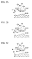
- each of the first connecting portions 31 and the second connecting portions 32 includes the projecting portions 41 and the connecting opening portions 42 provided on tip ends of the projecting portions 41.
- the projecting portions 41 project toward each of the positive electrode terminals 22 and the negative electrode terminals 23, and are elastically and/or plastically deformed.
- the projecting portion 41 includes the curved portion 41a which has a convex curved surface (for example, spherical surface) toward each of the positive electrode terminal 22 and the negative electrode terminal 23, and the connecting opening portion 42 is provided on the curved portion 41 a.
- the connecting opening portion 42 includes an inner wall portion 42b which forms the connecting opening 42a penetrating in a thickness direction in the curved portion 41a.
- the connecting opening portion 42 also includes the thinned portion 42c which is thinned in such a manner that a portion of an opposite side to the positive electrode terminal 22 and the negative electrode terminal 23 is cut off in the inner wall portions 42b.
- the projecting portion 41 according to the first example is joined to the positive electrode terminal 22 and the negative electrode terminal 23 by performing welding such as laser welding on the thinned portion 42c in a state that a surface of the curved portion 41a contacts with the positive electrode terminal 22 and the negative electrode terminal 23 while the connecting opening 42a approaches the positive electrode terminal 22 and the negative electrode terminal 23.
- the projecting portion 41 includes the curved portion 41a which has a convex curved surface (for example, spherical surface) toward each of the positive electrode terminal 22 and the negative electrode terminal 23, the planar portion 41b which has a planar surface, and the connecting opening portion 42 provided at the planar portion 41b.
- the connecting opening portion 42 includes the inner wall portion 42b which forms the connecting opening 42a penetrating in a thickness direction in the planar portion 41b.
- the connecting opening portion 42 also includes the thinned portion 42c which is thinned in such a manner that a portion of an opposite side to the positive electrode terminal 22 and the negative electrode terminal 23 is cut off in the inner wall portions 42b.
- the projecting portion 41 according to the second example is joined to the positive electrode terminal 22 and the negative electrode terminal 23 by performing welding such as laser welding on the thinned portion 42c in a state that a surface of the planar portion 41b contacts with the positive electrode terminal 22 and the negative electrode terminal 23 while the connecting opening 42a approaches the positive electrode terminal 22 and the negative electrode terminal 23.
- the projecting portion 41 includes the planar portion 41 c which has a plurality of planar surfaces convexly connected with each other toward the positive electrode terminal 22 and the negative electrode terminal 23, and the connecting opening portion 42 provided at the planar portion 41c.
- the connecting opening portion 42 includes the inner wall portion 42b which forms the connecting opening 42a penetrating in a thickness direction in the planar portion 41c.
- the connecting opening portion 42 also includes the thinned portion 42c which is thinned in such a manner that a portion of an opposite side to the positive electrode terminal 22 and the negative electrode terminal 23 is cut off in the inner wall portions 42b.
- the projecting portion 41 according to the third example is joined to the positive electrode terminal 22 and the negative electrode terminal 23 by performing welding such as laser welding on the thinned portion 42c in a state that a surface of the planar portion 41c contacts with the positive electrode terminal 22 and the negative electrode terminal 23 while the connecting opening 42a approaches the positive electrode terminal 22 and the negative electrode terminal 23.
- the coupling portion 33 is formed in such a manner that a cross-sectional surface swells in a convex shape for stress relaxation, such as a circular plate shape, U-plate shape or V-plate shape, in a direction separated from the secondary battery 12.
- deviation in heights of the positive electrode terminal 22 and the negative electrode terminal 23 and errors in a shape of the connecting busbar 27 may be removed by elastically and/or plastically deforming the projecting portion 41 which contacts with the positive electrode terminal 22 and the negative electrode terminal 23.
- the connecting busbar 27 may inhibit to generate gaps between the connecting busbar 27, and the positive electrode terminal 22 and the negative electrode terminal 23. Therefore it is possible to prevent to produce defects in a welding joint between the connecting busbar 27, and the positive electrode terminal 22 and the negative electrode terminal 23.
- FIG. 2A An implementation illustrated in the first example ( FIG. 2A ), which includes no planar portion in the projecting portion 41, allows the projecting portion 41 to have larger deformable range, and is able to suppress to generate gaps more effectively, as compared with the implementations illustrated in the second and third examples ( FIGS. 2B and 2C ) in which the planar portion 41b or 41c contacts with the positive electrode terminal 22 or the negative electrode terminal 23.
- the defects in the welding joint may be inhibited by contacting the planar portion 41b or 41c provided on the projecting portion 41 with the positive electrode terminal 22 or the negative electrode terminal 23.
- the implementation stated above include a pair of the first connecting portions 31 and a pair of the second connecting portions 32, each of which has a projecting portion 41.
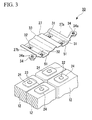
- the implementation is not limited thereto but may include, for example, a pair of the first connecting portions 31 which share the projecting portion 51, and a pair of the second connecting portions 32 which share the projecting portion 51, as the first modification example illustrated in FIG. 3 .
- the projecting portions 51 are formed by, for example, bending-forming a metal plate that configures the connecting busbar 27 so as to be projected toward the positive electrode terminal 22 and the negative electrode terminal 23.
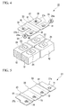
- the connecting busbar 27 may include the first end portion 27a and the second end portion 27b having a pair of the first connecting portions 31 and a pair of the second connecting portions 32, respectively, which are joined to the positive electrode terminal 22 and the negative electrode terminal 23, through the deforming portions 61 that are elastically and/or plastically deformed, as the second modification example illustrated in FIG. 4 .
- the connecting busbar 27 according to the second modification example is provided with the deforming portions 61, between the coupling portion 33 and the first end portion 27a, and between the coupling portion 33 and the second end portion 27b.
- the deforming portions 61 are elastically and/or plastically deformed, thereby further suppressing to generate gaps between the connecting busbar 27, and the positive electrode terminal 22 and the negative electrode terminal 23.
- the deforming portions 61 are positioned at locations provided on end portions of the connecting busbar 27, of portions contacting with the positive electrode terminal 22 and the negative electrode terminal 23 in the connecting busbar 27.
- the connecting busbar 27 has more than three connecting portions (for example, first to fourth connecting portions 71 to 74) which are serially coupled through the coupling portion 33.
- This connecting busbar 27 is provided with the deforming portions 61 which are displaced between the coupling portion 33 and the first end portion 27a having the first connecting portion 71, and between the coupling portion 33 and the second end portion 27b having the fourth connecting portion 74.
- the connecting busbar 27 including the deforming portions 61 may have the connecting opening portion 42 instead of the projecting portion 41, in the first connecting portions 31, the second connecting portions 32, and the first to fourth connecting portions 71 to 74.
- the implementation stated above includes the projecting portion 41 in the connecting busbar 27.
- the implementation is not limited thereto and may include the projecting portions 81 in the positive electrode terminal 22 and the negative electrode terminal 23 of the secondary battery 12.
- each of the positive electrode terminal 22 and the negative electrode terminal 23 is provided with the projecting portions 81 that project toward the connecting busbar 27.
- the projecting portions 81 have, for example, convex curved surfaces (for example, spherical surfaces) toward the connecting busbar 27.
- the connecting busbar 27 is preferably provided with at least the connecting opening portion 42 connected to each of the positive electrode terminal 22 and the negative electrode terminal 23 as illustrated in FIGS. 7A to 7D .
- the connecting busbar 27 illustrated in FIG. 6 has a shape of a substantially H-shaped plate, and includes a pair of the first connecting portions 31 provided on the first end portions 27a, a pair of the second connecting portions 32 provided on the second end portions 27b, and the coupling portion 33 that couples the first end portions 27a and the second end portions 27b.
- the connecting busbar 27 further includes the deforming portions 61.
- the deforming portions 61 are displaced between the connecting piece 34 having the screw hole 34a, and the coupling portion 33 and the first end portions 27a; and between the coupling portion 33 and the second end portions 27b.
- each of the first connecting portions 31 and the second connecting portions 32 is provided with, for example, the connecting opening portions 42 as illustrated in any one of FIGS. 7A to 7D .
- the connecting busbar 27 illustrated in FIG. 7A includes the connecting opening portion 42 provided on each of the first end portions 27a and the second end portions 27b, which have flat plate shape.
- the connecting busbar 27 is joined to the positive electrode terminal 22 and the negative electrode terminal 23 by performing welding such as laser welding on the thinned portion 42c in a state that the flat surfaces of each of the first end portions 27a and the second end portions 27b contact with the surfaces of the projecting portions 81 while the connecting opening 42a approaches to the projecting portions 81 of each of the positive electrode terminal 22 and the negative electrode terminal 23.
- the connecting busbar 27 illustrated in FIG. 7B includes the projecting portion 41 illustrated in the first example stated above and the connecting opening portion 42 in each of the first connecting portions 31 and the second connecting portions 32.
- the connecting busbar 27 is joined to the positive electrode terminal 22 and the negative electrode terminal 23 by performing welding such as laser welding on the thinned portion 42c in a state that the surface of the curved portion 41 a contacts with the surface of the projecting portion 81 while the connecting opening 42a approaches to the projecting portions 81 of each of the positive electrode terminal 22 and the negative electrode terminal 23.
- the connecting busbar 27 illustrated in FIG. 7C includes the projecting portion 41 illustrated in the second example stated above and the connecting opening portion 42 in each of the first connecting portions 31 and the second connecting portions 32.
- the connecting busbar 27 is joined to the positive electrode terminal 22 and the negative electrode terminal 23 by performing welding such as laser welding on the thinned portion 42c in a state that the surface of the planar portion 41b contacts with the surface of the projecting portion 81 while the connecting opening 42a approaches the projecting portions 81 of each of the positive electrode terminal 22 and the negative electrode terminal 23.
- the connecting busbar 27 illustrated in FIG. 7D includes the projecting portion 41 illustrated in the third example stated above and the connecting opening portion 42 in each of the first connecting portions 31 and the second connecting portions 32.
- the connecting busbar 27 is joined to the positive electrode terminal 22 and the negative electrode terminal 23 by performing welding such as laser welding on the thinned portion 42c in a state that the surface of the planar portion 41c contacts with the surface of the projecting portion 81 while the connecting opening 42a approaches the projecting portions 81 of each of the positive electrode terminal 22 and the negative electrode terminal 23.
- the fourth modification example it is able to further inhibit to generate gaps between the connecting busbar 27, and the positive electrode terminal 22 and the negative electrode terminal 23.
- the projecting portion 81 is not limited to the convex curved surface (for example, spherical surface) but may include the convex curved surface and the planar surface, or include a plurality of the planar surfaces convexly connected with each other instead of the curved surface.
Landscapes
- Chemical & Material Sciences (AREA)
- Chemical Kinetics & Catalysis (AREA)
- Electrochemistry (AREA)
- General Chemical & Material Sciences (AREA)
- Inorganic Chemistry (AREA)
- Connection Of Batteries Or Terminals (AREA)
- Battery Mounting, Suspending (AREA)
Priority Applications (1)
| Application Number | Priority Date | Filing Date | Title |
|---|---|---|---|
| EP15165669.1A EP2916371A1 (de) | 2013-11-20 | 2014-10-29 | Stromschiene für montierte batterie und montierte batterie |
Applications Claiming Priority (1)
| Application Number | Priority Date | Filing Date | Title |
|---|---|---|---|
| JP2013240307A JP2015099759A (ja) | 2013-11-20 | 2013-11-20 | 組電池用バスバーおよび組電池 |
Related Child Applications (2)
| Application Number | Title | Priority Date | Filing Date |
|---|---|---|---|
| EP15165669.1A Division-Into EP2916371A1 (de) | 2013-11-20 | 2014-10-29 | Stromschiene für montierte batterie und montierte batterie |
| EP15165669.1A Division EP2916371A1 (de) | 2013-11-20 | 2014-10-29 | Stromschiene für montierte batterie und montierte batterie |
Publications (2)
| Publication Number | Publication Date |
|---|---|
| EP2876705A2 true EP2876705A2 (de) | 2015-05-27 |
| EP2876705A3 EP2876705A3 (de) | 2015-07-15 |
Family
ID=51868022
Family Applications (2)
| Application Number | Title | Priority Date | Filing Date |
|---|---|---|---|
| EP14190864.0A Withdrawn EP2876705A3 (de) | 2013-11-20 | 2014-10-29 | Stromschiene für montierte Batterie |
| EP15165669.1A Withdrawn EP2916371A1 (de) | 2013-11-20 | 2014-10-29 | Stromschiene für montierte batterie und montierte batterie |
Family Applications After (1)
| Application Number | Title | Priority Date | Filing Date |
|---|---|---|---|
| EP15165669.1A Withdrawn EP2916371A1 (de) | 2013-11-20 | 2014-10-29 | Stromschiene für montierte batterie und montierte batterie |
Country Status (4)
| Country | Link |
|---|---|
| US (1) | US20150140391A1 (de) |
| EP (2) | EP2876705A3 (de) |
| JP (1) | JP2015099759A (de) |
| CN (1) | CN104659317A (de) |
Cited By (1)
| Publication number | Priority date | Publication date | Assignee | Title |
|---|---|---|---|---|
| EP3605658A1 (de) * | 2018-08-02 | 2020-02-05 | Saic Motor Corporation Limited | Flexible kupfersammelschiene und verfahren und vorrichtung zum entwerfen einer flexiblen kupfersammelschiene einer leistungsbatterie |
Families Citing this family (42)
| Publication number | Priority date | Publication date | Assignee | Title |
|---|---|---|---|---|
| JP6631866B2 (ja) * | 2015-01-09 | 2020-01-15 | 株式会社Gsユアサ | 蓄電装置 |
| US10137798B2 (en) * | 2015-08-04 | 2018-11-27 | Ford Global Technologies, Llc | Busbars for a power module assembly |
| JP6414018B2 (ja) * | 2015-10-29 | 2018-10-31 | トヨタ自動車株式会社 | 電池用バスバー |
| CN107068953A (zh) * | 2015-12-30 | 2017-08-18 | 昶洧新能源汽车发展有限公司 | 用于电动车辆电池组的集成汇流条和电池连接 |
| CN108604658B (zh) | 2016-01-29 | 2021-08-24 | 三洋电机株式会社 | 电源装置、车辆、汇流条以及电池单元的电连接方法 |
| JP2017142923A (ja) * | 2016-02-09 | 2017-08-17 | 株式会社オートネットワーク技術研究所 | バスバー及びバスバーの製造方法 |
| WO2018055676A1 (ja) * | 2016-09-20 | 2018-03-29 | 株式会社東芝 | 組電池および導電部材 |
| JP7114488B2 (ja) * | 2017-01-30 | 2022-08-08 | 三洋電機株式会社 | 電源装置 |
| CN109301634B (zh) * | 2017-07-24 | 2020-06-19 | 莫仕连接器(成都)有限公司 | 电池连接模块 |
| JP6653295B2 (ja) * | 2017-08-03 | 2020-02-26 | 矢崎総業株式会社 | バスバモジュールの電極接触構造 |
| KR102423609B1 (ko) * | 2017-09-29 | 2022-07-21 | 에스케이온 주식회사 | 이차 전지용 배터리 모듈 |
| WO2019124107A1 (ja) * | 2017-12-19 | 2019-06-27 | パナソニックIpマネジメント株式会社 | バスバー及び電池積層体 |
| TWI642221B (zh) * | 2017-12-21 | 2018-11-21 | 車王電子股份有限公司 | 電池導接片以及電池導接模組 |
| CN110010832B (zh) * | 2018-01-05 | 2022-01-21 | 车王电子股份有限公司 | 电池导接模块 |
| CN110048038B (zh) * | 2018-01-15 | 2022-03-15 | 车王电子股份有限公司 | 电池包 |
| JP6772203B2 (ja) * | 2018-01-16 | 2020-10-21 | 株式会社オートネットワーク技術研究所 | 接続モジュール |
| JP7152160B2 (ja) * | 2018-01-26 | 2022-10-12 | 矢崎総業株式会社 | バスバー及びバスバー固定構造 |
| US12021265B2 (en) * | 2018-03-28 | 2024-06-25 | Panasonic Intellectual Property Management Co., Ltd. | Bus bar and cell stack |
| JP6937268B2 (ja) * | 2018-06-13 | 2021-09-22 | 株式会社オートネットワーク技術研究所 | 蓄電素子モジュール |
| CN109192911A (zh) * | 2018-09-04 | 2019-01-11 | 王华珍 | 一种新能源电池成组焊接结构及焊接方法 |
| CN110911594B (zh) * | 2018-09-14 | 2024-09-06 | 宁德时代新能源科技股份有限公司 | 电池模组及其汇流构件和汇流组件 |
| JP2020102405A (ja) * | 2018-12-25 | 2020-07-02 | 矢崎総業株式会社 | 平型導体 |
| WO2020174954A1 (ja) * | 2019-02-27 | 2020-09-03 | 株式会社Gsユアサ | 蓄電装置 |
| CN113519086B (zh) * | 2019-03-12 | 2024-05-10 | 日本汽车能源株式会社 | 母线以及使用母线的电池模块 |
| KR102822163B1 (ko) * | 2019-07-05 | 2025-06-18 | 한국단자공업 주식회사 | 배터리셀용 전원연결장치 |
| JP2021026946A (ja) * | 2019-08-07 | 2021-02-22 | 矢崎総業株式会社 | 積層バスバの製造方法、積層バスバの製造装置及び積層バスバ |
| CN111584781B (zh) * | 2020-04-30 | 2021-11-02 | 东风汽车集团有限公司 | 一种长模组、电池模组、电池模组固定辅件及安装方法 |
| JP7252926B2 (ja) | 2020-09-17 | 2023-04-05 | プライムプラネットエナジー&ソリューションズ株式会社 | 二次電池用端子および該端子を備えた二次電池 |
| JP7256780B2 (ja) | 2020-09-17 | 2023-04-12 | プライムプラネットエナジー&ソリューションズ株式会社 | 二次電池用端子および二次電池用端子の製造方法 |
| EP4203171B1 (de) * | 2021-05-03 | 2025-10-15 | LG Energy Solution, Ltd. | Batteriemodul und batteriepack damit |
| DE102021206815A1 (de) | 2021-06-30 | 2023-01-05 | Robert Bosch Gesellschaft mit beschränkter Haftung | Akkupack |
| JP7402202B2 (ja) | 2021-07-15 | 2023-12-20 | プライムプラネットエナジー&ソリューションズ株式会社 | 端子部品および端子部品の製造方法 |
| JP7426356B2 (ja) | 2021-08-06 | 2024-02-01 | プライムプラネットエナジー&ソリューションズ株式会社 | 端子部品ならびに該端子部品を備える二次電池および組電池 |
| JP7481497B2 (ja) | 2021-08-23 | 2024-05-10 | 寧徳時代新能源科技股▲分▼有限公司 | 電池セル、その製造方法及び製造システム、電池並びに電力消費装置 |
| JP7512426B2 (ja) | 2021-08-23 | 2024-07-08 | 寧徳時代新能源科技股▲分▼有限公司 | 電池セル、その製造方法及び製造システム、電池並びに電力消費装置 |
| JP7455793B2 (ja) | 2021-11-17 | 2024-03-26 | プライムプラネットエナジー&ソリューションズ株式会社 | 電池モジュール |
| US20230178858A1 (en) * | 2021-12-08 | 2023-06-08 | Ford Global Technologies, Llc | Bus bar configurations for connecting battery pack components in parallel |
| CN114865232B (zh) * | 2022-05-30 | 2023-10-20 | 安徽久兴源新能源科技集团有限公司 | 一种解决电池焊接高低差的电池连接片 |
| DE102022122105A1 (de) * | 2022-09-01 | 2024-03-07 | Bayerische Motoren Werke Aktiengesellschaft | Batteriezelle, System, Verfahren zur Herstellung eines Batteriezellverbunds und Batteriezellverbund |
| JPWO2024128143A1 (de) * | 2022-12-15 | 2024-06-20 | ||
| CN116231234B (zh) * | 2023-05-09 | 2023-07-25 | 江苏正力新能电池技术有限公司 | 一种滑动抵接导电机构、电芯单体及电池包 |
| JP7811931B2 (ja) * | 2023-09-15 | 2026-02-06 | プライムプラネットエナジー&ソリューションズ株式会社 | バスバーおよび蓄電ユニット |
Citations (1)
| Publication number | Priority date | Publication date | Assignee | Title |
|---|---|---|---|---|
| JP2013196932A (ja) | 2012-03-21 | 2013-09-30 | Toshiba Corp | 二次電池装置 |
Family Cites Families (5)
| Publication number | Priority date | Publication date | Assignee | Title |
|---|---|---|---|---|
| KR100684846B1 (ko) * | 2005-07-29 | 2007-02-20 | 삼성에스디아이 주식회사 | 이차 전지 모듈 |
| JP5331450B2 (ja) * | 2008-11-07 | 2013-10-30 | 株式会社日立製作所 | 蓄電モジュール、蓄電装置、電動機駆動システムおよび車両 |
| KR20100067464A (ko) * | 2008-12-11 | 2010-06-21 | 삼성에스디아이 주식회사 | 전지 모듈 |
| US7972185B2 (en) * | 2009-03-16 | 2011-07-05 | Sb Limotive Co., Ltd. | Battery module having connector for connecting terminals |
| KR101244739B1 (ko) * | 2011-05-09 | 2013-03-18 | 로베르트 보쉬 게엠베하 | 전지 모듈 |
-
2013
- 2013-11-20 JP JP2013240307A patent/JP2015099759A/ja active Pending
-
2014
- 2014-10-29 EP EP14190864.0A patent/EP2876705A3/de not_active Withdrawn
- 2014-10-29 EP EP15165669.1A patent/EP2916371A1/de not_active Withdrawn
- 2014-10-30 CN CN201410781758.3A patent/CN104659317A/zh active Pending
- 2014-10-31 US US14/530,325 patent/US20150140391A1/en not_active Abandoned
Patent Citations (1)
| Publication number | Priority date | Publication date | Assignee | Title |
|---|---|---|---|---|
| JP2013196932A (ja) | 2012-03-21 | 2013-09-30 | Toshiba Corp | 二次電池装置 |
Cited By (1)
| Publication number | Priority date | Publication date | Assignee | Title |
|---|---|---|---|---|
| EP3605658A1 (de) * | 2018-08-02 | 2020-02-05 | Saic Motor Corporation Limited | Flexible kupfersammelschiene und verfahren und vorrichtung zum entwerfen einer flexiblen kupfersammelschiene einer leistungsbatterie |
Also Published As
| Publication number | Publication date |
|---|---|
| JP2015099759A (ja) | 2015-05-28 |
| CN104659317A (zh) | 2015-05-27 |
| EP2876705A3 (de) | 2015-07-15 |
| US20150140391A1 (en) | 2015-05-21 |
| EP2916371A1 (de) | 2015-09-09 |
Similar Documents
| Publication | Publication Date | Title |
|---|---|---|
| EP2876705A2 (de) | Stromschiene für montierte Batterie | |
| US11158911B2 (en) | Terminal connection structure, battery stack body, and method for forming terminal connection structure | |
| KR101280796B1 (ko) | 2차 전지용 버스바 및 2차 전지 모듈 | |
| US10069130B2 (en) | Sealed battery and manufacturing method of sealed battery | |
| US10256455B2 (en) | Secondary battery | |
| JPWO2017017915A1 (ja) | 電源装置及び電池セル用のバスバー | |
| US20150171412A1 (en) | Secondary battery collector terminal and secondary battery | |
| JP6460417B2 (ja) | 電池の製造方法 | |
| JP6260095B2 (ja) | 蓄電装置および二次電池 | |
| US20160315308A1 (en) | Current interruption device and electric storage device | |
| KR101856820B1 (ko) | 케이블형 이차전지 | |
| JP2009146601A (ja) | 角形密閉電池 | |
| JP2014053244A (ja) | 接続部材 | |
| JP2016092005A (ja) | 蓄電装置及び蓄電装置の製造方法 | |
| JP2017059346A (ja) | 二次電池および組電池 | |
| JP2010182441A (ja) | 電圧検知回路と電池セルとの接続構造 | |
| JP2015088267A (ja) | 組電池モジュール | |
| US9966585B2 (en) | Energy storage apparatus and method of manufacturing energy storage aparatus | |
| US10033025B2 (en) | Energy storage device including projecting portion located between bus bar and fastening member, and energy storage apparatus | |
| JP2014096388A (ja) | 電池 | |
| JP2018063784A (ja) | 二次電池 | |
| JP2008305564A (ja) | 密閉型電池 | |
| JP6152783B2 (ja) | 電流遮断装置とそれを用いた蓄電装置 | |
| JP2015005479A (ja) | 蓄電素子 | |
| JP2010086785A (ja) | 二次電池および電池モジュール |
Legal Events
| Date | Code | Title | Description |
|---|---|---|---|
| PUAI | Public reference made under article 153(3) epc to a published international application that has entered the european phase |
Free format text: ORIGINAL CODE: 0009012 |
|
| 17P | Request for examination filed |
Effective date: 20141029 |
|
| AK | Designated contracting states |
Kind code of ref document: A2 Designated state(s): AL AT BE BG CH CY CZ DE DK EE ES FI FR GB GR HR HU IE IS IT LI LT LU LV MC MK MT NL NO PL PT RO RS SE SI SK SM TR |
|
| AX | Request for extension of the european patent |
Extension state: BA ME |
|
| PUAL | Search report despatched |
Free format text: ORIGINAL CODE: 0009013 |
|
| AK | Designated contracting states |
Kind code of ref document: A3 Designated state(s): AL AT BE BG CH CY CZ DE DK EE ES FI FR GB GR HR HU IE IS IT LI LT LU LV MC MK MT NL NO PL PT RO RS SE SI SK SM TR |
|
| AX | Request for extension of the european patent |
Extension state: BA ME |
|
| RIC1 | Information provided on ipc code assigned before grant |
Ipc: H01M 2/10 20060101ALN20150610BHEP Ipc: H01M 2/02 20060101ALN20150610BHEP Ipc: H01M 2/20 20060101AFI20150610BHEP Ipc: H01M 2/30 20060101ALI20150610BHEP |
|
| STAA | Information on the status of an ep patent application or granted ep patent |
Free format text: STATUS: THE APPLICATION HAS BEEN WITHDRAWN |
|
| 18W | Application withdrawn |
Effective date: 20160310 |