EP2876778A1 - Installation électrique dotée d'une unité d'alimentation électrique sans coupure - Google Patents
Installation électrique dotée d'une unité d'alimentation électrique sans coupure Download PDFInfo
- Publication number
- EP2876778A1 EP2876778A1 EP13194042.1A EP13194042A EP2876778A1 EP 2876778 A1 EP2876778 A1 EP 2876778A1 EP 13194042 A EP13194042 A EP 13194042A EP 2876778 A1 EP2876778 A1 EP 2876778A1
- Authority
- EP
- European Patent Office
- Prior art keywords
- master
- consumers
- power supply
- supply unit
- electrical
- Prior art date
- Legal status (The legal status is an assumption and is not a legal conclusion. Google has not performed a legal analysis and makes no representation as to the accuracy of the status listed.)
- Granted
Links
Images

Classifications
-
- H—ELECTRICITY
- H02—GENERATION; CONVERSION OR DISTRIBUTION OF ELECTRIC POWER
- H02J—ELECTRIC POWER NETWORKS; CIRCUIT ARRANGEMENTS OR SYSTEMS FOR SUPPLYING OR DISTRIBUTING ELECTRIC POWER; SYSTEMS FOR STORING ELECTRIC ENERGY
- H02J13/00—Circuit arrangements for providing remote monitoring or remote control of equipment in a power distribution network
- H02J13/13—Circuit arrangements for providing remote monitoring or remote control of equipment in a power distribution network characterised by the transmission of data to equipment in the power network
- H02J13/1321—Circuit arrangements for providing remote monitoring or remote control of equipment in a power distribution network characterised by the transmission of data to equipment in the power network using a wired telecommunication network or a data transmission bus
-
- G—PHYSICS
- G06—COMPUTING OR CALCULATING; COUNTING
- G06F—ELECTRIC DIGITAL DATA PROCESSING
- G06F1/00—Details not covered by groups G06F3/00 - G06F13/00 and G06F21/00
- G06F1/26—Power supply means, e.g. regulation thereof
- G06F1/30—Means for acting in the event of power-supply failure or interruption, e.g. power-supply fluctuations
-
- G—PHYSICS
- G06—COMPUTING OR CALCULATING; COUNTING
- G06F—ELECTRIC DIGITAL DATA PROCESSING
- G06F11/00—Error detection; Error correction; Monitoring
- G06F11/07—Responding to the occurrence of a fault, e.g. fault tolerance
- G06F11/16—Error detection or correction of the data by redundancy in hardware
- G06F11/20—Error detection or correction of the data by redundancy in hardware using active fault-masking, e.g. by switching out faulty elements or by switching in spare elements
- G06F11/2015—Redundant power supplies
-
- H—ELECTRICITY
- H02—GENERATION; CONVERSION OR DISTRIBUTION OF ELECTRIC POWER
- H02J—ELECTRIC POWER NETWORKS; CIRCUIT ARRANGEMENTS OR SYSTEMS FOR SUPPLYING OR DISTRIBUTING ELECTRIC POWER; SYSTEMS FOR STORING ELECTRIC ENERGY
- H02J9/00—Circuit arrangements for emergency or stand-by power supply, e.g. for emergency lighting
- H02J9/04—Circuit arrangements for emergency or stand-by power supply, e.g. for emergency lighting in which the distribution system is disconnected from the normal source and connected to a standby source
- H02J9/06—Circuit arrangements for emergency or stand-by power supply, e.g. for emergency lighting in which the distribution system is disconnected from the normal source and connected to a standby source with automatic change-over, e.g. UPS systems
- H02J9/061—Circuit arrangements for emergency or stand-by power supply, e.g. for emergency lighting in which the distribution system is disconnected from the normal source and connected to a standby source with automatic change-over, e.g. UPS systems for DC powered loads
-
- Y—GENERAL TAGGING OF NEW TECHNOLOGICAL DEVELOPMENTS; GENERAL TAGGING OF CROSS-SECTIONAL TECHNOLOGIES SPANNING OVER SEVERAL SECTIONS OF THE IPC; TECHNICAL SUBJECTS COVERED BY FORMER USPC CROSS-REFERENCE ART COLLECTIONS [XRACs] AND DIGESTS
- Y02—TECHNOLOGIES OR APPLICATIONS FOR MITIGATION OR ADAPTATION AGAINST CLIMATE CHANGE
- Y02B—CLIMATE CHANGE MITIGATION TECHNOLOGIES RELATED TO BUILDINGS, e.g. HOUSING, HOUSE APPLIANCES OR RELATED END-USER APPLICATIONS
- Y02B70/00—Technologies for an efficient end-user side electric power management and consumption
- Y02B70/30—Systems integrating technologies related to power network operation and communication or information technologies for improving the carbon footprint of the management of residential or tertiary loads, i.e. smart grids as climate change mitigation technology in the buildings sector, including also the last stages of power distribution and the control, monitoring or operating management systems at local level
-
- Y—GENERAL TAGGING OF NEW TECHNOLOGICAL DEVELOPMENTS; GENERAL TAGGING OF CROSS-SECTIONAL TECHNOLOGIES SPANNING OVER SEVERAL SECTIONS OF THE IPC; TECHNICAL SUBJECTS COVERED BY FORMER USPC CROSS-REFERENCE ART COLLECTIONS [XRACs] AND DIGESTS
- Y02—TECHNOLOGIES OR APPLICATIONS FOR MITIGATION OR ADAPTATION AGAINST CLIMATE CHANGE
- Y02B—CLIMATE CHANGE MITIGATION TECHNOLOGIES RELATED TO BUILDINGS, e.g. HOUSING, HOUSE APPLIANCES OR RELATED END-USER APPLICATIONS
- Y02B90/00—Enabling technologies or technologies with a potential or indirect contribution to GHG emissions mitigation
- Y02B90/20—Smart grids as enabling technology in buildings sector
-
- Y—GENERAL TAGGING OF NEW TECHNOLOGICAL DEVELOPMENTS; GENERAL TAGGING OF CROSS-SECTIONAL TECHNOLOGIES SPANNING OVER SEVERAL SECTIONS OF THE IPC; TECHNICAL SUBJECTS COVERED BY FORMER USPC CROSS-REFERENCE ART COLLECTIONS [XRACs] AND DIGESTS
- Y04—INFORMATION OR COMMUNICATION TECHNOLOGIES HAVING AN IMPACT ON OTHER TECHNOLOGY AREAS
- Y04S—SYSTEMS INTEGRATING TECHNOLOGIES RELATED TO POWER NETWORK OPERATION, COMMUNICATION OR INFORMATION TECHNOLOGIES FOR IMPROVING THE ELECTRICAL POWER GENERATION, TRANSMISSION, DISTRIBUTION, MANAGEMENT OR USAGE, i.e. SMART GRIDS
- Y04S20/00—Management or operation of end-user stationary applications or the last stages of power distribution; Controlling, monitoring or operating thereof
- Y04S20/12—Energy storage units, uninterruptible power supply [UPS] systems or standby or emergency generators, e.g. in the last power distribution stages
-
- Y—GENERAL TAGGING OF NEW TECHNOLOGICAL DEVELOPMENTS; GENERAL TAGGING OF CROSS-SECTIONAL TECHNOLOGIES SPANNING OVER SEVERAL SECTIONS OF THE IPC; TECHNICAL SUBJECTS COVERED BY FORMER USPC CROSS-REFERENCE ART COLLECTIONS [XRACs] AND DIGESTS
- Y04—INFORMATION OR COMMUNICATION TECHNOLOGIES HAVING AN IMPACT ON OTHER TECHNOLOGY AREAS
- Y04S—SYSTEMS INTEGRATING TECHNOLOGIES RELATED TO POWER NETWORK OPERATION, COMMUNICATION OR INFORMATION TECHNOLOGIES FOR IMPROVING THE ELECTRICAL POWER GENERATION, TRANSMISSION, DISTRIBUTION, MANAGEMENT OR USAGE, i.e. SMART GRIDS
- Y04S20/00—Management or operation of end-user stationary applications or the last stages of power distribution; Controlling, monitoring or operating thereof
- Y04S20/20—End-user application control systems
- Y04S20/248—UPS systems or standby or emergency generators
-
- Y—GENERAL TAGGING OF NEW TECHNOLOGICAL DEVELOPMENTS; GENERAL TAGGING OF CROSS-SECTIONAL TECHNOLOGIES SPANNING OVER SEVERAL SECTIONS OF THE IPC; TECHNICAL SUBJECTS COVERED BY FORMER USPC CROSS-REFERENCE ART COLLECTIONS [XRACs] AND DIGESTS
- Y04—INFORMATION OR COMMUNICATION TECHNOLOGIES HAVING AN IMPACT ON OTHER TECHNOLOGY AREAS
- Y04S—SYSTEMS INTEGRATING TECHNOLOGIES RELATED TO POWER NETWORK OPERATION, COMMUNICATION OR INFORMATION TECHNOLOGIES FOR IMPROVING THE ELECTRICAL POWER GENERATION, TRANSMISSION, DISTRIBUTION, MANAGEMENT OR USAGE, i.e. SMART GRIDS
- Y04S40/00—Systems for electrical power generation, transmission, distribution or end-user application management characterised by the use of communication or information technologies, or communication or information technology specific aspects supporting them
- Y04S40/12—Systems for electrical power generation, transmission, distribution or end-user application management characterised by the use of communication or information technologies, or communication or information technology specific aspects supporting them characterised by data transport means between the monitoring, controlling or managing units and monitored, controlled or operated electrical equipment
- Y04S40/124—Systems for electrical power generation, transmission, distribution or end-user application management characterised by the use of communication or information technologies, or communication or information technology specific aspects supporting them characterised by data transport means between the monitoring, controlling or managing units and monitored, controlled or operated electrical equipment using wired telecommunication networks or data transmission busses
Definitions
- the invention relates to a method for operating an electrical system having a plurality of electrical loads, which are connected to a basic supply voltage and are connected in case of failure of the basic supply voltage to a buffer voltage to ensure the supply of electrical loads for a period of a buffer phase, wherein the buffer voltage is provided by means of an uninterruptible power supply unit.
- the invention relates to an electrically operated system for carrying out the method.
- an uninterruptible power supply unit which implements a special shutdown management via special function blocks, can not completely resolve complicated dependencies among the participants. It comes in the preparation for the upcoming shutdown inconsistencies and data loss. Furthermore, the system can not continue to operate properly even when power is restored in buffer mode. There is downtime.
- an uninterruptible power supply for a rotary printing press is known in which a control sequence can be triggered in the event of a fault in the supply voltage, in accordance with which the rotary printing press can be moved to a production stop defined by default.
- a control sequence can be triggered in the event of a fault in the supply voltage, in accordance with which the rotary printing press can be moved to a production stop defined by default.
- the object of the invention is to improve the abovementioned method and the abovementioned system for carrying out the method such that a plurality of machines, ie a plurality of electrical consumers, are also available in the event of a lack of the basic supply voltage, taking into account the limited available Storage energy of the uninterruptible power supply unit can be moved to a safe state.
- a controlled shutdown can be realized by locally installed in the electrical consumers software modules.
- the uninterruptible power supply unit in an electrical System be involved in such a data technology that the electrical consumers, such as control components, programmable logic controllers or control systems, an occurrence of the lack of basic supply voltage can take into account in good time. If the uninterruptible power supply unit changes from a normal operation to an operation in which a buffer voltage is provided, the uninterruptible power supply unit can only provide this buffer voltage for a certain period of time of a buffer phase. With the software modules installed in the electrical consumers and the signaling of the absence of the basic supply voltage by the uninterruptible power supply unit, the electrical consumers can prepare early for an imminent shutdown due to the change of the uninterruptible power supply from the normal operation in the buffer operation.
- the method is improved by the fact that the master makes available a subscriber list and the consumers are entered in the subscriber list by means of their software modules set as slave.
- the master provides an empty list of participants, all software modules that are parameterized as slave, register with the master with their relevant information, while the list of participants with information about addresses, device types, energy consumption, time periods, etc., filled.
- devices from the groups programmable logic controllers, operating and monitoring systems, industrial or personal computers are used as electrical consumers.
- an uninterruptible power supply unit is provided, which is configured, in case of failure of the basic supply voltage to turn on a buffer voltage to the electrical load to ensure the supply of electrical loads for a period of a buffer phase, wherein the power supply unit is configured, data via a fieldbus with the plurality of electrical consumer, wherein the plurality of electrical consumers each having a software component which is configured to communicate via the fieldbus, the software component of at least one consumer as a master and the software components of other consumers as a slave in the sense of a master-slave Communication are configured.
- the power supply unit is designed as a communication partner of the master for carrying out a regulated shutdown of the electrical load.
- the power supply unit is configured in the case of a lack of the basic supply voltage to notify this lack of the field bus to the master.
- the master and the software components of the consumer are designed to perform the shutdown in configurable synchronization stages. At each synchronization stage is deposited for each consumer in its respective software component, whether the consumer should maintain or change its energetic state and, if several energetic state changes are possible and provided, in which energetic state to be changed.
- the master is configured to sequentially signal the consumers each synchronization stage.
- Consumers are configured to handle the energetic state changes stored in the software modules for the respective synchronization stage, and the software modules are configured to report this to the master after completion of the energetic state changes for the respective synchronization stage.
- the master has a subscriber list and the consumers are configured to register themselves in the subscriber list by means of their software modules set as slave.
- the consumers are configured to register themselves in the subscriber list by means of their software modules set as slave.
- information about addresses, device types, energy consumption, periods of a shutdown, etc. are entered into the subscriber list.
- the power supply unit, the electrical consumers and the software components are configured in such a way that they can be parameterized via a software tool.
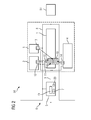
- FIG. 1 is an electrically operated system 50 with a plurality of electrical consumers 1 to 4 shown.
- a first consumer 1 is configured as an industrial PC with a process control software, an archive, a license module and a word program
- a second consumer 2 is configured as an industrial HMI panel for operating and monitoring a process
- a third consumer 3 is as a programmable controller designed to control a sub-process
- a fourth consumer 4 is designed as a control system industrial PC with a control and monitoring program and a software-based programmable logic controller.
- the consumers 1 to 4 are connected via a power supply line 9 to an uninterruptible power supply unit 5.
- the uninterruptible power supply unit 5 receives a basic supply voltage 6 via a 24 V supply line. This basic supply voltage 6 switches in normal operation via a switching device 7a to the electrical consumers 1 to 4. In the event of a failure of the basic supply voltage 6, the uninterruptible power supply unit 5 is designed to switch by means of the switching device 7a on a battery module with a buffer voltage 7 and to provide the electrical loads 1 to 4 via the power supply line 9 with the buffer voltage 7.
- the buffer voltage 7 is connected to the electrical loads 1 to 4 in order to ensure the supply of the electrical consumers for a period of a buffer phase.
- a bridging time period 20 may be in the range of 20 seconds to a few minutes. That is, during the bridging period 20, the Electric consumers continue to work normally, although buffer operation prevails. Should the basic supply voltage 6 not return within the bridging time period 20, then a controlled switch-off process of the individual electrical consumers 1 to 4 is started by means of software components 11 to 14 installed in the electrical consumers 1 to 4.
- the first consumer 1 has a first software component 11, the second consumer 2 a second software component 12, the third consumer 3 a third software component 13 and the fourth consumer 4 a fourth software component 14.
- the software modules 11 to 14 are parameterized with respect to their consumers 1 to 4 with an individual shutdown sequence. This parameterization can be carried out by a software tool 51 which, like the software modules 11, 12, 13, 14, is connected to a fieldbus 8.
- FIG. 2 receives a special electrical consumer, namely the first consumer 1, in addition or in combination a special software component, namely a fifth software module 15, which is designed as a master M in the sense of a master-slave communication, while the software modules are 11 to 14 as a slave S to the master M designed.
- a special electrical consumer namely the first consumer 1
- a special software component namely a fifth software module 15
- the software modules are 11 to 14 as a slave S to the master M designed.
- the master M has a subscriber list 10, wherein the consumers 1 to 4 are configured by means of their set as slave S software modules 11 to 14 to register in the subscriber list 10.
- the master M is configured to perform data traffic between the uninterruptible power supply unit 5 and itself. Accordingly, the master M is able to request data of the uninterruptible power supply unit 5 and to process them.
- the master M controls the software modules 11 to 14 in the consumers 1 to 4.
- the bridging time period 20 is stored, while the master M is configured to query the bridging time period 20 and additionally configured to measure with the beginning of the absence of the basic supply voltage 6, which he gets notified by a signal of the uninterruptible power supply unit 5, as Since the absence already persists and in the event that the absence lasts longer than the bridging time period, the master is configured to send an instruction to the slaves S to start their respective individual shutdown sequence.
- the master is configured to monitor the individual shutdown sequences by means of the subscriber list 10 and to start its own shutdown sequence after successfully performing the individual shutdown sequences, this in turn is in the first software block 11 in addition to the master M implemented, wherein the master in turn announces the start of its own shutdown sequence of the uninterruptible power supply unit 5, which then turns off the buffer voltage after completion of the shutdown sequence of the first software module 11.
- the electrical system 50 is in a defined, safe state.
- the method or the software components 11 to 14 are designed or parameterized such that a time-controlled shutdown, an energy-controlled shutdown or a shutdown after synchronization stages can be selected for the shutdown process.
- the software modules in the form of a master M can advantageously be present in two variants, namely for example a Microsoft Windows PC as a software application or for example, a programmable logic controller as a function block.
- the software blocks in their function as slaves can also be present as a Microsoft Windows PC software application, as a function block for programmable logic controllers or as a Microsoft Windows CE software application, for example for HMI panels.
- the software modules are to be referred to below as agents and advantageously have an operable via the software tool 51 user interface.
- Agents that are installed on a PC system or on an HMI panel therefore, log on to an operator of the electrical system 50 as a self-explanatory user interface.
- the user interface of the master agent offers a choice between the time- and energy-controlled shutdown. If the timed shutdown is selected, the user interface offers further setting options, such as Time until the start of the shutdown phase, on. When selecting the energy-controlled shutdown, the user interface offers input options of the amount of energy that is consumed in the shutdown phase by the plant part or electrical consumer. There is also the option of making a subdivision of the shutdown phases in synchronization stages in the user interface.
- An illustration of the subscriber list 10, which is managed by the master agent, is further provided in the user interface. However, the data transmitted by the slave agent are only displayed as "read-only".
- a slave agent user interface provides a selection of a file (usually a .bat or .exe file) at startup the buffer operation (equal to the beginning of the transition phase) to be performed on the electrical load on. Also, a file can be selected, which should be executed at the beginning of the shutdown on the electrical load.
- a file usually a .bat or .exe file
- an editable, 16-line table is displayed. The 16 lines symbolize the maximum number of synchronization levels. The operator of the electrical system can make entries in the individual lines about files to be executed and time outs.
- an operator has opted for the second case, that is to say in the event that an electrical system should continue to operate as long as possible after the basic supply voltage has been discontinued - and for as long as the energy store of the uninterruptible power supply unit allows it - then it wants a shutdown the electrical consumer really only if the remaining energy in the battery module is sufficient only to reliably shut down the individual electrical loads and a Voltage return of the basic supply voltage 6 has failed.
- the operator of the electrical system 50 must determine the energy consumption in the shutdown phase in advance for each electrical load. With the determined or calculated values, he finds the minimum size of the capacity of the battery module, which would be just enough for a considered part of the plant or for the electrical system to safely shut them down.
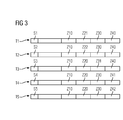
- FIG. 3 By way of example, the sequence of a switch-off process in configurable synchronization stages is shown.
- five synchronization stages S1, S2, S3, S4, and S5 are employed, for each of which a predetermined period of time T1, T2, T3, T4, and T5 is predetermined according to the duration of the actions.
- the master M individually signals the consumers 1, 2, 3, 4 each synchronization stage, beginning with the synchronization stage 1, for which the time period T1 is predetermined. Subsequently, the stored in the associated software modules 11,12,13 and 14 energetic state change ZXX the consumers are 1,2,3,4 done for the synchronization stage 1. After these state changes ZXX have been carried out, the corresponding software module 11, 12, 13, 14 reports this for acknowledgment to the master M.
- the master M After the master M has received the acknowledgment from all consumers 1, 2, 3, 4 or at the latest after the expiration of the time duration T1, the master M indicates the next synchronization stage.
- the signal "Shutdown reached” is sent to the master M by the slaves, which are located on subscribers or consumers without operating system. This will be noted in the list of participants. In the event of voltage recovery, it may still be possible to return to normal operation.
- the last synchronization stage concerns, for example, the operating system, eg the termination of the operating system on the lower PC, ie in the consumer 4 according to FIG. 1 ,
- the system can be put back into normal operation by the control program - depending on the synchronization stages - run up the system again and establish normal operation. Downtime is thus completely avoided as the preparation process for the upcoming shutdown is aborted.
- a specific synchronization threshold can be marked as "Point of no return” via the special function module. If this synchronization threshold is signaled to the participants, the complete preparation process for the imminent shutdown must be carried out, since the system can no longer be put into normal operation "without further ado". This may be the case, for example, when a PC system is being shut down without the system being able to operate normally. The label "Point of no return” thus also contributes to safety.
Landscapes
- Engineering & Computer Science (AREA)
- Theoretical Computer Science (AREA)
- Power Engineering (AREA)
- Physics & Mathematics (AREA)
- General Engineering & Computer Science (AREA)
- General Physics & Mathematics (AREA)
- Business, Economics & Management (AREA)
- Emergency Management (AREA)
- Quality & Reliability (AREA)
- Remote Monitoring And Control Of Power-Distribution Networks (AREA)
- Safety Devices In Control Systems (AREA)
- Stand-By Power Supply Arrangements (AREA)
Priority Applications (4)
| Application Number | Priority Date | Filing Date | Title |
|---|---|---|---|
| EP13194042.1A EP2876778B1 (fr) | 2013-11-22 | 2013-11-22 | Installation électrique dotée d'une unité d'alimentation électrique sans coupure |
| RU2014139022A RU2014139022A (ru) | 2013-11-22 | 2014-09-26 | Электроустановка с блоком бесперебойного питания |
| US14/542,162 US9430013B2 (en) | 2013-11-22 | 2014-11-14 | Electrical installation having an uninterruptible power supply |
| CN201410671016.5A CN104659901B (zh) | 2013-11-22 | 2014-11-20 | 具有不中断的供电单元的电设备 |
Applications Claiming Priority (1)
| Application Number | Priority Date | Filing Date | Title |
|---|---|---|---|
| EP13194042.1A EP2876778B1 (fr) | 2013-11-22 | 2013-11-22 | Installation électrique dotée d'une unité d'alimentation électrique sans coupure |
Publications (2)
| Publication Number | Publication Date |
|---|---|
| EP2876778A1 true EP2876778A1 (fr) | 2015-05-27 |
| EP2876778B1 EP2876778B1 (fr) | 2017-08-02 |
Family
ID=49683465
Family Applications (1)
| Application Number | Title | Priority Date | Filing Date |
|---|---|---|---|
| EP13194042.1A Active EP2876778B1 (fr) | 2013-11-22 | 2013-11-22 | Installation électrique dotée d'une unité d'alimentation électrique sans coupure |
Country Status (4)
| Country | Link |
|---|---|
| US (1) | US9430013B2 (fr) |
| EP (1) | EP2876778B1 (fr) |
| CN (1) | CN104659901B (fr) |
| RU (1) | RU2014139022A (fr) |
Cited By (2)
| Publication number | Priority date | Publication date | Assignee | Title |
|---|---|---|---|---|
| US11093014B2 (en) | 2018-02-15 | 2021-08-17 | Siemens Aktiengesellschaft | Method for monitoring, control and graceful shutdown of control and/or computer units |
| CN113964928A (zh) * | 2021-10-14 | 2022-01-21 | 成都光电传感技术研究所有限公司 | 一种dc-dc适配电源及其转换控制方法 |
Families Citing this family (2)
| Publication number | Priority date | Publication date | Assignee | Title |
|---|---|---|---|---|
| DE202019101746U1 (de) * | 2019-03-27 | 2020-06-30 | Wago Verwaltungsgesellschaft Mbh | Elektronikgerät und Kommunikationseinheit |
| CN112486593B (zh) * | 2020-11-30 | 2023-06-23 | 重庆芯讯通无线科技有限公司 | 主从模块的配置信息的同步方法及系统 |
Citations (5)
| Publication number | Priority date | Publication date | Assignee | Title |
|---|---|---|---|---|
| US5734230A (en) * | 1995-06-01 | 1998-03-31 | Continuum Corporation | Fail-safe lighting system with load shedding and dimming |
| EP1223656A1 (fr) | 2000-12-22 | 2002-07-17 | MAN Roland Druckmaschinen AG | Alimentation pour une machine rotative d'impression |
| US20090251002A1 (en) * | 2008-04-02 | 2009-10-08 | American Power Conversion Corporation | Apparatus, system and method for a ups |
| US20130124000A1 (en) * | 2010-07-23 | 2013-05-16 | Sharp Kabushiki Kaisha | Power control network system, power control method, and power controller |
| US20130169046A1 (en) * | 2011-12-12 | 2013-07-04 | Samsung Electronics Co., Ltd. | Power consumption control apparatus and power consumption control method |
Family Cites Families (7)
| Publication number | Priority date | Publication date | Assignee | Title |
|---|---|---|---|---|
| US6274950B1 (en) * | 1994-03-03 | 2001-08-14 | American Power Conversion | Battery communication system |
| US5964609A (en) * | 1995-01-25 | 1999-10-12 | Haworth, Inc. | Modular communication cabling arrangement |
| US5994794A (en) * | 1997-05-09 | 1999-11-30 | Active Power, Inc. | Methods and apparatus for providing protection to batteries in an uninterruptible power supply |
| US6433444B1 (en) * | 2000-02-18 | 2002-08-13 | General Electric Company | Modular fault tolerant power distribution system |
| US7478251B1 (en) * | 2004-12-23 | 2009-01-13 | Cisco Technology, Inc. | Methods and apparatus for provisioning uninterruptible power for power over Ethernet applications |
| EP1952503A4 (fr) * | 2005-11-02 | 2010-12-08 | Server Tech Inc | Systeme de delestage de charge de distribution de courant et son procede d'utilisation |
| US20100289335A1 (en) * | 2009-05-12 | 2010-11-18 | Radhakrishna Togare | Active back up auto changeover voltage bus |
-
2013
- 2013-11-22 EP EP13194042.1A patent/EP2876778B1/fr active Active
-
2014
- 2014-09-26 RU RU2014139022A patent/RU2014139022A/ru not_active Application Discontinuation
- 2014-11-14 US US14/542,162 patent/US9430013B2/en active Active
- 2014-11-20 CN CN201410671016.5A patent/CN104659901B/zh active Active
Patent Citations (5)
| Publication number | Priority date | Publication date | Assignee | Title |
|---|---|---|---|---|
| US5734230A (en) * | 1995-06-01 | 1998-03-31 | Continuum Corporation | Fail-safe lighting system with load shedding and dimming |
| EP1223656A1 (fr) | 2000-12-22 | 2002-07-17 | MAN Roland Druckmaschinen AG | Alimentation pour une machine rotative d'impression |
| US20090251002A1 (en) * | 2008-04-02 | 2009-10-08 | American Power Conversion Corporation | Apparatus, system and method for a ups |
| US20130124000A1 (en) * | 2010-07-23 | 2013-05-16 | Sharp Kabushiki Kaisha | Power control network system, power control method, and power controller |
| US20130169046A1 (en) * | 2011-12-12 | 2013-07-04 | Samsung Electronics Co., Ltd. | Power consumption control apparatus and power consumption control method |
Cited By (3)
| Publication number | Priority date | Publication date | Assignee | Title |
|---|---|---|---|---|
| US11093014B2 (en) | 2018-02-15 | 2021-08-17 | Siemens Aktiengesellschaft | Method for monitoring, control and graceful shutdown of control and/or computer units |
| CN113964928A (zh) * | 2021-10-14 | 2022-01-21 | 成都光电传感技术研究所有限公司 | 一种dc-dc适配电源及其转换控制方法 |
| CN113964928B (zh) * | 2021-10-14 | 2023-11-14 | 成都光电传感技术研究所有限公司 | 一种dc-dc适配电源及其转换控制方法 |
Also Published As
| Publication number | Publication date |
|---|---|
| RU2014139022A (ru) | 2016-04-20 |
| CN104659901A (zh) | 2015-05-27 |
| CN104659901B (zh) | 2019-01-15 |
| EP2876778B1 (fr) | 2017-08-02 |
| US20150149821A1 (en) | 2015-05-28 |
| US9430013B2 (en) | 2016-08-30 |
Similar Documents
| Publication | Publication Date | Title |
|---|---|---|
| EP3622357B1 (fr) | Système de commande servant à commander des processus critiques pour la sécurité et non-critiques pour la sécurité, muni d'une fonctionnalité maître-esclave | |
| EP2876778B1 (fr) | Installation électrique dotée d'une unité d'alimentation électrique sans coupure | |
| EP2630751A2 (fr) | Procédé et dispositif pour configurer des dispositifs utilisateurs de réseau | |
| EP2490372A1 (fr) | Réseau en temps réel planifié de manière topologique indépendant du port | |
| DE102019117960A1 (de) | Ventilkontrollsystem und Verfahren | |
| EP2787405B1 (fr) | Procédé de fonctionnement d'une installation électrique et installation électrique | |
| EP2997427B1 (fr) | Système de commande et procédé de commutation de modules d'entrée/sortie d'un système de commande | |
| EP2798418B1 (fr) | Dispositif et procédé de constitution automatique de séquences de mise en fonctionnement dans une installation | |
| EP3082001B1 (fr) | Procédé d'extension d'un dispositif d'automatisation avec un virtuel appareil d'automatisation et dispositif d'automatisation | |
| EP3602732B1 (fr) | Procédé de fonctionnement d'une installation électrique comprenant une pluralité de consommateurs électriques, alimentation électrique et installation électrique | |
| EP2993537A1 (fr) | Diagnostic d'erreurs dans des systèmes d'automatisation | |
| DE102011122516A1 (de) | Verfahren zum Reduzieren des Ressourcenverbrauchs von Automatisierungsanlagen | |
| WO2008074736A1 (fr) | Dispositif de commande pour au moins un moteur électrique et équipé d'un régulateur coopérant avec le dispositif de commande | |
| EP2002316B1 (fr) | Dispositif de commande a modele de machine integre | |
| WO2014161986A1 (fr) | Installation de commande et transfert de données pour la commande de processus redondante et procédé de mise à jour de microprogrammes | |
| EP2455827A1 (fr) | Appareil de terrain avec un mode de basse consommation qui peut être activé et désactivé au travers des deux interfaces de l' appareil de terrain | |
| EP2620819B1 (fr) | Procédé de mise en service et/ou de désactivation automatiques de composants d'un agencement d'automatisation industriel | |
| DE102011122515A1 (de) | Ereignisschnittstelle für Energiemanagementsystem | |
| EP1307793B1 (fr) | Procede pour exploiter un dispositif de commutation de securite et dispositif de commutation de securite | |
| AT521134B1 (de) | Industrieanlage | |
| EP1790069B1 (fr) | Procede pour deconnecter au moins une partie de regulation d'un appareil convertisseur de courant | |
| EP4246549A1 (fr) | Procédé de commande des états de commutation | |
| EP1203664B1 (fr) | Connection et mise hors-service pour une machine à imprimer | |
| EP3207430B1 (fr) | Dispositif pour la commande coordonnée d'un état de fonctionnement d'une installation de production ainsi que système de production et procédé | |
| EP3026514B1 (fr) | Installation d'automatisation et procédé de commande externe d'un algorithme d'autocontrôle dans un dispositif de sécurité décentralisé |
Legal Events
| Date | Code | Title | Description |
|---|---|---|---|
| PUAI | Public reference made under article 153(3) epc to a published international application that has entered the european phase |
Free format text: ORIGINAL CODE: 0009012 |
|
| 17P | Request for examination filed |
Effective date: 20131122 |
|
| AK | Designated contracting states |
Kind code of ref document: A1 Designated state(s): AL AT BE BG CH CY CZ DE DK EE ES FI FR GB GR HR HU IE IS IT LI LT LU LV MC MK MT NL NO PL PT RO RS SE SI SK SM TR |
|
| AX | Request for extension of the european patent |
Extension state: BA ME |
|
| R17P | Request for examination filed (corrected) |
Effective date: 20151120 |
|
| RBV | Designated contracting states (corrected) |
Designated state(s): AL AT BE BG CH CY CZ DE DK EE ES FI FR GB GR HR HU IE IS IT LI LT LU LV MC MK MT NL NO PL PT RO RS SE SI SK SM TR |
|
| REG | Reference to a national code |
Ref country code: DE Ref legal event code: R079 Ref document number: 502013007912 Country of ref document: DE Free format text: PREVIOUS MAIN CLASS: H02J0009060000 Ipc: G06F0001300000 |
|
| GRAP | Despatch of communication of intention to grant a patent |
Free format text: ORIGINAL CODE: EPIDOSNIGR1 |
|
| RIC1 | Information provided on ipc code assigned before grant |
Ipc: H02J 13/00 20060101ALI20170202BHEP Ipc: H02J 9/06 20060101ALI20170202BHEP Ipc: G06F 11/20 20060101ALI20170202BHEP Ipc: G06F 1/30 20060101AFI20170202BHEP |
|
| INTG | Intention to grant announced |
Effective date: 20170224 |
|
| GRAS | Grant fee paid |
Free format text: ORIGINAL CODE: EPIDOSNIGR3 |
|
| GRAA | (expected) grant |
Free format text: ORIGINAL CODE: 0009210 |
|
| AK | Designated contracting states |
Kind code of ref document: B1 Designated state(s): AL AT BE BG CH CY CZ DE DK EE ES FI FR GB GR HR HU IE IS IT LI LT LU LV MC MK MT NL NO PL PT RO RS SE SI SK SM TR |
|
| REG | Reference to a national code |
Ref country code: CH Ref legal event code: EP Ref country code: AT Ref legal event code: REF Ref document number: 915146 Country of ref document: AT Kind code of ref document: T Effective date: 20170815 |
|
| REG | Reference to a national code |
Ref country code: IE Ref legal event code: FG4D Free format text: LANGUAGE OF EP DOCUMENT: GERMAN |
|
| RAP2 | Party data changed (patent owner data changed or rights of a patent transferred) |
Owner name: SIEMENS AKTIENGESELLSCHAFT |
|
| REG | Reference to a national code |
Ref country code: DE Ref legal event code: R096 Ref document number: 502013007912 Country of ref document: DE |
|
| REG | Reference to a national code |
Ref country code: CH Ref legal event code: NV Representative=s name: SIEMENS SCHWEIZ AG, CH Ref country code: CH Ref legal event code: PCOW |
|
| REG | Reference to a national code |
Ref country code: NL Ref legal event code: MP Effective date: 20170802 |
|
| REG | Reference to a national code |
Ref country code: LT Ref legal event code: MG4D |
|
| PG25 | Lapsed in a contracting state [announced via postgrant information from national office to epo] |
Ref country code: HR Free format text: LAPSE BECAUSE OF FAILURE TO SUBMIT A TRANSLATION OF THE DESCRIPTION OR TO PAY THE FEE WITHIN THE PRESCRIBED TIME-LIMIT Effective date: 20170802 Ref country code: NL Free format text: LAPSE BECAUSE OF FAILURE TO SUBMIT A TRANSLATION OF THE DESCRIPTION OR TO PAY THE FEE WITHIN THE PRESCRIBED TIME-LIMIT Effective date: 20170802 Ref country code: LT Free format text: LAPSE BECAUSE OF FAILURE TO SUBMIT A TRANSLATION OF THE DESCRIPTION OR TO PAY THE FEE WITHIN THE PRESCRIBED TIME-LIMIT Effective date: 20170802 Ref country code: SE Free format text: LAPSE BECAUSE OF FAILURE TO SUBMIT A TRANSLATION OF THE DESCRIPTION OR TO PAY THE FEE WITHIN THE PRESCRIBED TIME-LIMIT Effective date: 20170802 Ref country code: NO Free format text: LAPSE BECAUSE OF FAILURE TO SUBMIT A TRANSLATION OF THE DESCRIPTION OR TO PAY THE FEE WITHIN THE PRESCRIBED TIME-LIMIT Effective date: 20171102 Ref country code: FI Free format text: LAPSE BECAUSE OF FAILURE TO SUBMIT A TRANSLATION OF THE DESCRIPTION OR TO PAY THE FEE WITHIN THE PRESCRIBED TIME-LIMIT Effective date: 20170802 |
|
| PG25 | Lapsed in a contracting state [announced via postgrant information from national office to epo] |
Ref country code: PL Free format text: LAPSE BECAUSE OF FAILURE TO SUBMIT A TRANSLATION OF THE DESCRIPTION OR TO PAY THE FEE WITHIN THE PRESCRIBED TIME-LIMIT Effective date: 20170802 Ref country code: RS Free format text: LAPSE BECAUSE OF FAILURE TO SUBMIT A TRANSLATION OF THE DESCRIPTION OR TO PAY THE FEE WITHIN THE PRESCRIBED TIME-LIMIT Effective date: 20170802 Ref country code: ES Free format text: LAPSE BECAUSE OF FAILURE TO SUBMIT A TRANSLATION OF THE DESCRIPTION OR TO PAY THE FEE WITHIN THE PRESCRIBED TIME-LIMIT Effective date: 20170802 Ref country code: GR Free format text: LAPSE BECAUSE OF FAILURE TO SUBMIT A TRANSLATION OF THE DESCRIPTION OR TO PAY THE FEE WITHIN THE PRESCRIBED TIME-LIMIT Effective date: 20171103 Ref country code: IS Free format text: LAPSE BECAUSE OF FAILURE TO SUBMIT A TRANSLATION OF THE DESCRIPTION OR TO PAY THE FEE WITHIN THE PRESCRIBED TIME-LIMIT Effective date: 20171202 Ref country code: BG Free format text: LAPSE BECAUSE OF FAILURE TO SUBMIT A TRANSLATION OF THE DESCRIPTION OR TO PAY THE FEE WITHIN THE PRESCRIBED TIME-LIMIT Effective date: 20171102 Ref country code: LV Free format text: LAPSE BECAUSE OF FAILURE TO SUBMIT A TRANSLATION OF THE DESCRIPTION OR TO PAY THE FEE WITHIN THE PRESCRIBED TIME-LIMIT Effective date: 20170802 |
|
| PG25 | Lapsed in a contracting state [announced via postgrant information from national office to epo] |
Ref country code: DK Free format text: LAPSE BECAUSE OF FAILURE TO SUBMIT A TRANSLATION OF THE DESCRIPTION OR TO PAY THE FEE WITHIN THE PRESCRIBED TIME-LIMIT Effective date: 20170802 Ref country code: RO Free format text: LAPSE BECAUSE OF FAILURE TO SUBMIT A TRANSLATION OF THE DESCRIPTION OR TO PAY THE FEE WITHIN THE PRESCRIBED TIME-LIMIT Effective date: 20170802 Ref country code: CZ Free format text: LAPSE BECAUSE OF FAILURE TO SUBMIT A TRANSLATION OF THE DESCRIPTION OR TO PAY THE FEE WITHIN THE PRESCRIBED TIME-LIMIT Effective date: 20170802 |
|
| REG | Reference to a national code |
Ref country code: DE Ref legal event code: R097 Ref document number: 502013007912 Country of ref document: DE |
|
| PG25 | Lapsed in a contracting state [announced via postgrant information from national office to epo] |
Ref country code: IT Free format text: LAPSE BECAUSE OF FAILURE TO SUBMIT A TRANSLATION OF THE DESCRIPTION OR TO PAY THE FEE WITHIN THE PRESCRIBED TIME-LIMIT Effective date: 20170802 Ref country code: EE Free format text: LAPSE BECAUSE OF FAILURE TO SUBMIT A TRANSLATION OF THE DESCRIPTION OR TO PAY THE FEE WITHIN THE PRESCRIBED TIME-LIMIT Effective date: 20170802 Ref country code: SM Free format text: LAPSE BECAUSE OF FAILURE TO SUBMIT A TRANSLATION OF THE DESCRIPTION OR TO PAY THE FEE WITHIN THE PRESCRIBED TIME-LIMIT Effective date: 20170802 Ref country code: SK Free format text: LAPSE BECAUSE OF FAILURE TO SUBMIT A TRANSLATION OF THE DESCRIPTION OR TO PAY THE FEE WITHIN THE PRESCRIBED TIME-LIMIT Effective date: 20170802 |
|
| PLBE | No opposition filed within time limit |
Free format text: ORIGINAL CODE: 0009261 |
|
| STAA | Information on the status of an ep patent application or granted ep patent |
Free format text: STATUS: NO OPPOSITION FILED WITHIN TIME LIMIT |
|
| PG25 | Lapsed in a contracting state [announced via postgrant information from national office to epo] |
Ref country code: MC Free format text: LAPSE BECAUSE OF FAILURE TO SUBMIT A TRANSLATION OF THE DESCRIPTION OR TO PAY THE FEE WITHIN THE PRESCRIBED TIME-LIMIT Effective date: 20170802 |
|
| 26N | No opposition filed |
Effective date: 20180503 |
|
| GBPC | Gb: european patent ceased through non-payment of renewal fee |
Effective date: 20171122 |
|
| PG25 | Lapsed in a contracting state [announced via postgrant information from national office to epo] |
Ref country code: LI Free format text: LAPSE BECAUSE OF NON-PAYMENT OF DUE FEES Effective date: 20171130 Ref country code: CH Free format text: LAPSE BECAUSE OF NON-PAYMENT OF DUE FEES Effective date: 20171130 |
|
| PG25 | Lapsed in a contracting state [announced via postgrant information from national office to epo] |
Ref country code: SI Free format text: LAPSE BECAUSE OF FAILURE TO SUBMIT A TRANSLATION OF THE DESCRIPTION OR TO PAY THE FEE WITHIN THE PRESCRIBED TIME-LIMIT Effective date: 20170802 Ref country code: LU Free format text: LAPSE BECAUSE OF NON-PAYMENT OF DUE FEES Effective date: 20171122 |
|
| REG | Reference to a national code |
Ref country code: FR Ref legal event code: ST Effective date: 20180731 Ref country code: BE Ref legal event code: MM Effective date: 20171130 |
|
| REG | Reference to a national code |
Ref country code: IE Ref legal event code: MM4A |
|
| PG25 | Lapsed in a contracting state [announced via postgrant information from national office to epo] |
Ref country code: MT Free format text: LAPSE BECAUSE OF FAILURE TO SUBMIT A TRANSLATION OF THE DESCRIPTION OR TO PAY THE FEE WITHIN THE PRESCRIBED TIME-LIMIT Effective date: 20170802 |
|
| PG25 | Lapsed in a contracting state [announced via postgrant information from national office to epo] |
Ref country code: IE Free format text: LAPSE BECAUSE OF NON-PAYMENT OF DUE FEES Effective date: 20171122 Ref country code: FR Free format text: LAPSE BECAUSE OF NON-PAYMENT OF DUE FEES Effective date: 20171130 |
|
| PG25 | Lapsed in a contracting state [announced via postgrant information from national office to epo] |
Ref country code: BE Free format text: LAPSE BECAUSE OF NON-PAYMENT OF DUE FEES Effective date: 20171130 Ref country code: GB Free format text: LAPSE BECAUSE OF NON-PAYMENT OF DUE FEES Effective date: 20171122 |
|
| PG25 | Lapsed in a contracting state [announced via postgrant information from national office to epo] |
Ref country code: HU Free format text: LAPSE BECAUSE OF FAILURE TO SUBMIT A TRANSLATION OF THE DESCRIPTION OR TO PAY THE FEE WITHIN THE PRESCRIBED TIME-LIMIT; INVALID AB INITIO Effective date: 20131122 |
|
| PG25 | Lapsed in a contracting state [announced via postgrant information from national office to epo] |
Ref country code: CY Free format text: LAPSE BECAUSE OF FAILURE TO SUBMIT A TRANSLATION OF THE DESCRIPTION OR TO PAY THE FEE WITHIN THE PRESCRIBED TIME-LIMIT Effective date: 20170802 |
|
| PG25 | Lapsed in a contracting state [announced via postgrant information from national office to epo] |
Ref country code: MK Free format text: LAPSE BECAUSE OF FAILURE TO SUBMIT A TRANSLATION OF THE DESCRIPTION OR TO PAY THE FEE WITHIN THE PRESCRIBED TIME-LIMIT Effective date: 20170802 |
|
| REG | Reference to a national code |
Ref country code: AT Ref legal event code: MM01 Ref document number: 915146 Country of ref document: AT Kind code of ref document: T Effective date: 20181122 |
|
| PG25 | Lapsed in a contracting state [announced via postgrant information from national office to epo] |
Ref country code: AT Free format text: LAPSE BECAUSE OF NON-PAYMENT OF DUE FEES Effective date: 20181122 |
|
| PG25 | Lapsed in a contracting state [announced via postgrant information from national office to epo] |
Ref country code: TR Free format text: LAPSE BECAUSE OF FAILURE TO SUBMIT A TRANSLATION OF THE DESCRIPTION OR TO PAY THE FEE WITHIN THE PRESCRIBED TIME-LIMIT Effective date: 20170802 |
|
| PG25 | Lapsed in a contracting state [announced via postgrant information from national office to epo] |
Ref country code: PT Free format text: LAPSE BECAUSE OF FAILURE TO SUBMIT A TRANSLATION OF THE DESCRIPTION OR TO PAY THE FEE WITHIN THE PRESCRIBED TIME-LIMIT Effective date: 20170802 |
|
| PG25 | Lapsed in a contracting state [announced via postgrant information from national office to epo] |
Ref country code: AL Free format text: LAPSE BECAUSE OF FAILURE TO SUBMIT A TRANSLATION OF THE DESCRIPTION OR TO PAY THE FEE WITHIN THE PRESCRIBED TIME-LIMIT Effective date: 20170802 |
|
| PGFP | Annual fee paid to national office [announced via postgrant information from national office to epo] |
Ref country code: DE Payment date: 20260119 Year of fee payment: 13 |