EP2876820A1 - Verfahren und Knoten in einem drahtlosen Kommunikationssystem - Google Patents
Verfahren und Knoten in einem drahtlosen Kommunikationssystem Download PDFInfo
- Publication number
- EP2876820A1 EP2876820A1 EP13193971.2A EP13193971A EP2876820A1 EP 2876820 A1 EP2876820 A1 EP 2876820A1 EP 13193971 A EP13193971 A EP 13193971A EP 2876820 A1 EP2876820 A1 EP 2876820A1
- Authority
- EP
- European Patent Office
- Prior art keywords
- real
- list
- valued
- mimo
- hypotheses
- Prior art date
- Legal status (The legal status is an assumption and is not a legal conclusion. Google has not performed a legal analysis and makes no representation as to the accuracy of the status listed.)
- Granted
Links
- 238000000034 method Methods 0.000 title claims abstract description 91
- 238000004891 communication Methods 0.000 title claims abstract description 40
- 239000013598 vector Substances 0.000 claims abstract description 80
- 238000001514 detection method Methods 0.000 claims abstract description 47
- 238000012545 processing Methods 0.000 claims description 62
- 238000007792 addition Methods 0.000 claims description 53
- 239000011159 matrix material Substances 0.000 claims description 34
- 238000004590 computer program Methods 0.000 claims description 13
- 230000002829 reductive effect Effects 0.000 claims description 12
- 230000001629 suppression Effects 0.000 claims description 6
- 230000009471 action Effects 0.000 description 38
- 230000000875 corresponding effect Effects 0.000 description 12
- 230000014509 gene expression Effects 0.000 description 10
- 230000005540 biological transmission Effects 0.000 description 9
- 230000009467 reduction Effects 0.000 description 9
- 238000007781 pre-processing Methods 0.000 description 8
- 238000012360 testing method Methods 0.000 description 8
- 238000010586 diagram Methods 0.000 description 7
- 238000005516 engineering process Methods 0.000 description 6
- 238000011156 evaluation Methods 0.000 description 6
- 238000001914 filtration Methods 0.000 description 6
- 238000013459 approach Methods 0.000 description 5
- 230000000670 limiting effect Effects 0.000 description 5
- 238000004088 simulation Methods 0.000 description 5
- 238000003860 storage Methods 0.000 description 5
- 238000007476 Maximum Likelihood Methods 0.000 description 4
- 230000001413 cellular effect Effects 0.000 description 4
- 230000006870 function Effects 0.000 description 4
- 230000007774 longterm Effects 0.000 description 4
- 238000012805 post-processing Methods 0.000 description 4
- 230000001174 ascending effect Effects 0.000 description 3
- 238000013507 mapping Methods 0.000 description 3
- 238000010295 mobile communication Methods 0.000 description 3
- 238000013468 resource allocation Methods 0.000 description 3
- 230000009286 beneficial effect Effects 0.000 description 2
- 230000008901 benefit Effects 0.000 description 2
- 230000001419 dependent effect Effects 0.000 description 2
- 230000000694 effects Effects 0.000 description 2
- 238000002474 experimental method Methods 0.000 description 2
- 230000003287 optical effect Effects 0.000 description 2
- 230000000135 prohibitive effect Effects 0.000 description 2
- 238000013138 pruning Methods 0.000 description 2
- XUIMIQQOPSSXEZ-UHFFFAOYSA-N Silicon Chemical compound [Si] XUIMIQQOPSSXEZ-UHFFFAOYSA-N 0.000 description 1
- 230000002776 aggregation Effects 0.000 description 1
- 238000004220 aggregation Methods 0.000 description 1
- 230000004075 alteration Effects 0.000 description 1
- 238000010276 construction Methods 0.000 description 1
- 230000001276 controlling effect Effects 0.000 description 1
- 230000002596 correlated effect Effects 0.000 description 1
- 230000003247 decreasing effect Effects 0.000 description 1
- 238000013461 design Methods 0.000 description 1
- 238000009472 formulation Methods 0.000 description 1
- 238000003306 harvesting Methods 0.000 description 1
- 230000006872 improvement Effects 0.000 description 1
- 230000006698 induction Effects 0.000 description 1
- 230000001788 irregular Effects 0.000 description 1
- 239000000203 mixture Substances 0.000 description 1
- 238000012986 modification Methods 0.000 description 1
- 230000004048 modification Effects 0.000 description 1
- 230000036961 partial effect Effects 0.000 description 1
- 230000010363 phase shift Effects 0.000 description 1
- 238000000746 purification Methods 0.000 description 1
- 230000002441 reversible effect Effects 0.000 description 1
- 230000011664 signaling Effects 0.000 description 1
- 229910052710 silicon Inorganic materials 0.000 description 1
- 239000010703 silicon Substances 0.000 description 1
- 230000003595 spectral effect Effects 0.000 description 1
- 238000006467 substitution reaction Methods 0.000 description 1
- 230000001360 synchronised effect Effects 0.000 description 1
- 230000009466 transformation Effects 0.000 description 1
- 238000000844 transformation Methods 0.000 description 1
- 238000011144 upstream manufacturing Methods 0.000 description 1
Images


Classifications
-
- H—ELECTRICITY
- H04—ELECTRIC COMMUNICATION TECHNIQUE
- H04B—TRANSMISSION
- H04B7/00—Radio transmission systems, i.e. using radiation field
- H04B7/02—Diversity systems; Multi-antenna system, i.e. transmission or reception using multiple antennas
- H04B7/04—Diversity systems; Multi-antenna system, i.e. transmission or reception using multiple antennas using two or more spaced independent antennas
- H04B7/08—Diversity systems; Multi-antenna system, i.e. transmission or reception using multiple antennas using two or more spaced independent antennas at the receiving station
- H04B7/0837—Diversity systems; Multi-antenna system, i.e. transmission or reception using multiple antennas using two or more spaced independent antennas at the receiving station using pre-detection combining
- H04B7/0842—Weighted combining
- H04B7/0848—Joint weighting
- H04B7/0854—Joint weighting using error minimizing algorithms, e.g. minimum mean squared error [MMSE], "cross-correlation" or matrix inversion
Definitions
- Implementations described herein generally relate to a user equipment and a method in a user equipment.
- an improved MIMO detection scheme is herein described.
- a User Equipment also known as a recipient, a mobile station, wireless terminal and/ or mobile terminal is enabled to communicate wirelessly in a wireless communication system, sometimes also referred to as a cellular radio system or a wireless communication network.
- the communication may be made, e.g., between UEs, between a UE and a wire connected telephone and/ or between a UE and a server via a Radio Access Network (RAN) and possibly one or more core networks.
- RAN Radio Access Network
- the wireless communication may comprise various communication services such as voice, messaging, packet data, video, broadcast, etc.
- the UE may further be referred to as mobile telephone, cellular telephone, computer tablet or laptop with wireless capability, etc.
- the UE in the present context may be, for example, portable, pocket-storable, hand-held, computer-comprised, or vehicle-mounted mobile devices, enabled to communicate voice and/ or data, via the radio access network, with another entity, such as another UE or a server.
- the wireless communication system covers a geographical area which is, in some access technologies, divided into cell areas, with each cell area being served by a radio network node, or base station, e.g., a Radio Base Station (RBS) or Base Transceiver Station (BTS), which in some networks may be referred to as "eNB”, “eNodeB”, “NodeB” or “B node”, depending on the technology and/ or terminology used.
- a radio network node e.g., a Radio Base Station (RBS) or Base Transceiver Station (BTS)
- eNB Radio Base Station
- eNodeB NodeB
- NodeB NodeB node
- the expression "cell” may be used for denoting the radio network node itself. However, the cell may also in normal terminology be used for the geographical area where radio coverage is provided by the radio network node at a base station site.
- One radio network node, situated on the base station site, may serve one or several cells.
- the radio network nodes may communicate over the air interface operating on radio frequencies with any UE within range of the respective radio network node.
- radio network nodes may be connected, e.g., by landlines or microwave, to a Radio Network Controller (RNC), e.g., in Universal Mobile Telecommunications System (UMTS).
- RNC Radio Network Controller
- UMTS Universal Mobile Telecommunications System
- BSC Base Station Controller
- GSM Global System for Mobile Communications
- radio network nodes which may be referred to as eNodeBs or eNBs, may be connected to a gateway, e.g., a radio access gateway, to one or more core networks.
- a gateway e.g., a radio access gateway
- the expressions downlink (DL), downstream link or forward link may be used for the transmission path from the radio network node to the UE.
- the expression uplink (UL), upstream link or reverse link may be used for the transmission path in the opposite direction, i.e., from the UE to the radio network node.
- 3GPP LTE offer high data rate in the downlink by employing Multiple Input and Multiple-Output (MIMO) with Orthogonal Frequency Division Multiplexing (OFDM) access scheme at the UE receiver.
- MIMO Multiple Input and Multiple-Output
- OFDM Orthogonal Frequency Division Multiplexing
- downlink can support up to 300 Mbps data rate; and in LTE-Advanced, e.g., UE category 8, can support data rates up to 3 Gbps (Gigabits per second), i.e., up to 8 layers.
- MLM full max-log-MAP
- a MIMO detector is sought, that is robust against, large N and M, and various channel code rates. Further, an efficient implementation of such detector is also required. Hence, four requirements may be put on such detector, namely:
- target (i) and parts of target (iii) of the above specified requirements may be partly solved in the following way:
- the requirement (iii) may be partly fulfilled since the search space can be smaller for most of the modulation and coding rates compared to the full search and simultaneously meeting the requirement (i).
- the requirement (iii) may be partly fulfilled since the search space can be smaller for most of the modulation and coding rates compared to the full search and simultaneously meeting the requirement (i).
- LMMSE Linear Minimum Mean Square Error
- the focus of this disclosure is to develop a detector that inherits the requirements (i) and (iii) from known prior art methods, but extends it in such a way that the requirement (iv) is adequately addressed, while at the same time extending known prior art computation techniques so that the technique is no longer only applicable for full search, i.e., MLM, but also can be used for the detectors, thereby achieving also requirement (ii).
- a general problem is to provide novel detector and detection scheme that meet the aforementioned requirements (i) - (iv) have to be searched for in order to provide efficient MIMO detection.
- a method in a User Equipment (UE) for Multiple-Input and Multiple-Output (MIMO) detection of signals received from a radio network node, comprised in a wireless communication network.
- the method comprises receiving a signal of the radio network node.
- the method in addition comprises establishing a list of hypotheses candidate vector.
- the method also comprises computing path metrics (aka, Euclidean distances) of the established list of hypotheses candidate vector, and thereby computing Log-Likelihood Ratios (LLRs) utilising the computed path metrics for achieving MIMO detection.
- path metrics aka, Euclidean distances
- the method further comprises computing Linear Minimum Mean Square Error (LMMSE) estimate of the transmitted modulation alphabet via the received signal.
- LMMSE Linear Minimum Mean Square Error
- the computation of LMMSE is made on a complex- valued received signal.
- the method further comprises performing soft parallel interference cancellation with MMSE of the received signal on a given number of iterations.
- the performance of soft parallel interference cancellation comprises MMSE filtering on a complex- valued received signal.
- the establishment of the list of hypotheses candidate vector is based on possible combinations of the calculated most likely candidates per spatial layer.
- the method further comprises converting complex-valued received signal into real-valued; thereby obtaining four 2x2 real-valued groups (assuming 4x4 complex-valued MIMO detection problem) by utilising Subspace Marginalisation Interference Suppression (SUMIS) algorithm; and obtaining a set of most likely candidates for each 2x2 reak-valued groups, after having a set of most likely candidates for each group, and forming a list of all possible hypotheses candidate vector based on the candidates found in 2x2 real-valued groups.
- SUMIS Subspace Marginalisation Interference Suppression
- the LLRs are utilised from the first stage processing, which is LMMSE/ MMSE-SPIC demodulation.
- a candidate reduction technique is utilised in order to reduce the list of hypotheses candidate vector by pruning the most unlikely candidates' combinations forming the hypotheses.
- the computed path metrics of the established list of hypotheses candidate vector is evaluated recursively over a tree structure.
- the computed path metrics of the established list of hypotheses candidate vector is expressed in the recursive form as:
- the number of additions is reduced such that: a depth 4 matrix requires 2 M 4 M 3 M 2 M 1 + M 4 M 2 M 1 + M 4 M 1 real additions; a depth 3 matrix requires 2 M 3 M 2 M 1 + M 3 M 1 real additions; and a depth 2 matrix requires 2 M 2 M 1 real additions.
- the wireless communication network is based on 3rd Generation Partnership Project Long Term Evolution (3GPP LTE) and the radio network node comprises an evolved NodeB (eNodeB).
- 3GPP LTE 3rd Generation Partnership Project Long Term Evolution
- eNodeB evolved NodeB
- a UE configured for MIMO detection of signals received from a radio network node, comprised in a wireless communication network
- the UE comprises a receiving circuit, configured for receiving signals from the radio network node.
- the UE comprises a processing circuit, configured for establishing a list of hypotheses candidate vector, and also configured for computing path metrics of the established list of hypotheses candidate vector by computing LLR, utilising the computed path metrics for achieving MIMO detection.
- the processing circuit may be further configured for LMMSE estimate of transmitted modulation alphabet via the received signal.
- the processing circuit is further configured for computing LMMSE on a complex valued received signal.
- the processing circuit is further configured for performing soft parallel interference cancellation with MMSE of the received signal on a given number of iterations.
- the processing circuit is further configured for performing the soft parallel interference cancellation comprises MMSE filtering on a complex- valued received signal.
- the processing circuit is further configured for calculating the most likely candidates per spatial layer independently for each layer.
- the processing circuit is further configured for establishing the list of hypotheses candidate vector based on possible combinations of the calculated most likely candidates per spatial layer.
- the processing circuit is further configured for converting complex-valued received signal into real-valued; and thereby obtaining four 2x2 real-valued groups by utilising SUMIS algorithm; and also configured for obtaining a set of most likely candidates for each 2x2 real-valued groups, after having a set of most likely candidates for each group, and forming a list of all possible hypotheses candidate vector based on the candidates found in 2x2 real-valued groups.
- the processing circuit is further configured for utilising the LLRs from the first stage processing.
- the processing circuit is further configured for computing LMMSE of the received signal by utilising knowledge about errors in channel estimation.
- the processing circuit is further configured for utilising a candidate reduction technique in order to reduce the number of candidates before calculating the most likely candidates per spatial layer independently for each layer.
- the processing circuit is further configured for computing path metrics of the established list of hypotheses candidate vector, evaluated recursively over a tree structure.
- the processing circuit is further configured for reducing the number of additions such that: a depth 4 matrix requires 2 M 4 M 3 M 2 M 1 + M 4 M 2 M 1 + M 4 M 1 real additions; a depth 3 matrix requires 2 M 3 M 2 M 1 + M 3 M 1 real additions; and a depth 2 matrix requires 2 M 2 M 1 real additions.
- the wireless communication network is based on 3GPP LTE and wherein the radio network node comprises an eNodeB.
- a computer program product is provided in a UE according to the second aspect, or any previous possible implementation of the second aspect, for performing a method according to the first aspect or any previous possible implementation of the first aspect, for MIMO detection of signals received from a radio network node, when the computer program product is loaded in a processing circuit of the UE.
- near-optimal and fixed-complexity MIMO detectors which obtain the LLRs by utilising the hypotheses candidate vectors in the reduced space and dimension.
- knowledge about errors in the channel estimation can easily be employed in the detection part and thereby improve performance.
- a candidate reduction technique is also disclosed to further reduce the cost of the complexity.
- the disclosed detectors have a constant/ fixed complexity. Further, the numbers of arithmetic operations are fairly low. Furthermore, the detectors are robust against all the modulation and code-rates, and the typical channel conditions.
- the performance of the disclosed detectors is comparable to full search of type Max-log-Maximum A-posteriori (MLM). Thus an improved performance within a wireless communication system is provided.
- MLM Max-log-Maximum A-posteriori
- Embodiments of the invention described herein are defined as a UE and a method in the UE which may be put into practice in the embodiments described below. These embodiments may, however, be exemplified and realised in many different forms and are not to be limited to the examples set forth herein; rather, these illustrative examples of embodiments are provided so that this disclosure will be thorough and complete.
- FIG. 1A is a schematic illustration over a wireless communication system 100 comprising a radio network node 110 communicating with a User Equipment (UE) 120, which is served by the radio network node 110.
- UE User Equipment
- the wireless communication system 100 may at least partly be based on radio access technologies such as, e.g., 3GPP LTE, LTE-Advanced, Evolved Universal Terrestrial Radio Access Network (E-UTRAN), Universal Mobile Telecommunications System (UMTS), Global System for Mobile Communications (originally: Groupe Spécial Mobile) (GSM)/ Enhanced Data rate for GSM Evolution (GSM/EDGE), Wideband Code Division Multiple Access (WCDMA), Time Division Multiple Access (TDMA) networks, Frequency Division Multiple Access (FDMA) networks, Orthogonal FDMA (OFDMA) networks, Single-Carrier FDMA (SC-FDMA) networks, Worldwide Interoperability for Microwave Access (WiMax), or Ultra Mobile Broadband (UMB), High Speed Packet Access (HSPA) Evolved Universal Terrestrial Radio Access (E-UTRA), Universal Terrestrial Radio Access (UTRA), GSM EDGE Radio Access Network (GERAN), 3GPP2 CDMA technologies, e.g., CDMA2000 1x RTT
- the wireless communication system 100 may be configured for carrier aggregation of a Frequency Division Duplex (FDD) carrier and at least one Time Division Duplex (TDD) carrier, according to different embodiments, in the downlink.
- FDD Frequency Division Duplex
- TDD Time Division Duplex
- FIG. 1A The purpose of the illustration in Figure 1A is to provide a simplified, general overview of the wireless communication system 100 and the involved methods and nodes, such as the radio network node 110 and UE 120 herein described, and the functionalities involved.
- the method and wireless communication system 100 will subsequently, as a non-limiting example, be described in a 3GPP LTE/ LTE-Advanced environment, but the embodiments of the disclosed method and wireless communication system 100 may be based on another access technology such as, e.g., any of the above already enumerated.
- 3GPP LTE Long Term Evolution
- LTE-Advanced environment 3GPP LTE/ LTE-Advanced environment
- the embodiments of the disclosed method and wireless communication system 100 may be based on another access technology such as, e.g., any of the above already enumerated.
- 3GPP LTE 3GPP LTE/ LTE-Advanced environment
- the illustrated wireless communication system 100 comprises the radio network node 110, which may send radio signals to be received by the UE 120.
- the wireless communication system 100 may comprise any other number and/ or combination of radio network nodes 110 and/ or UE 120.
- a plurality of UEs 120 and another configuration of radio network nodes 110 may thus be involved in some embodiments of the disclosed invention.
- UE 120 and/ or radio network node 110 may be involved, according to some embodiments.
- the radio network node 110 may according to some embodiments be configured for downlink transmission and may be referred to, respectively, as e.g., a base station, NodeB, evolved Node Bs (eNB, or eNodeB), base transceiver station, Access Point Base Station, base station router, Radio Base Station (RBS), micro base station, pico base station, femto base station, Home eNodeB, sensor, beacon device, relay node, repeater or any other network node configured for communication with the UE 120 over a wireless interface, depending, e.g., of the radio access technology and/ or terminology used.
- a base station NodeB, evolved Node Bs (eNB, or eNodeB), base transceiver station, Access Point Base Station, base station router, Radio Base Station (RBS), micro base station, pico base station, femto base station, Home eNodeB, sensor, beacon device, relay node, repeater or any other network node configured for communication with the UE 120
- the UE 120 may correspondingly be represented by, e.g. a wireless communication terminal, a mobile cellular phone, a Personal Digital Assistant (PDA), a wireless platform, a mobile station, a tablet computer, a portable communication device, a laptop, a computer, a wireless terminal acting as a relay, a relay node, a mobile relay, a Customer Premises Equipment (CPE), a Fixed Wireless Access (FWA) nodes or any other kind of device configured to communicate wirelessly with the radio network node 110, according to different embodiments and different vocabulary.
- PDA Personal Digital Assistant
- PDA Personal Digital Assistant
- a wireless platform e.g., a wireless platform
- a mobile station e.g., a mobile station, a tablet computer, a portable communication device, a laptop, a computer, a wireless terminal acting as a relay, a relay node, a mobile relay, a Customer Premises Equipment (CPE), a Fixed Wireless Access (FWA) nodes or any other kind of device
- FIG. 1B is a schematic illustration of an embodiment illustrating a near-optimal and efficient MIMO detection scheme.
- MMSE Minimum Mean Square Error
- SPIC Soft Parallel Interference Cancellation
- RD-MLS Maximum Likelihood Search
- wireless signals are received from a radio network node 110.
- an LMMSE estimate of the transmitted modulation alphabet via received signal may be computed.
- soft parallel interference cancellation may be performed, with MMSE on the received signal for the given number of iterations.
- soft-MMSE may be employed with parallel interference cancellation, or alternatively successive interference cancellation in different embodiments.
- the first stage detector may be referred to as either MMSE-SPIC or soft-MMSE-PIC, interchangeably.
- the soft-bits for the PIC operation can either be utilised based on the MIMO demodulator itself or the channel decoder, or possibly the hybrid operation over the iterations.
- MMSE-SPIC may obtain the most likely candidates per spatial layer independently, without any joint processing across spatial layers, in some embodiments.
- a list of hypotheses candidate vector may be created based on all the possible combinations of the candidates obtained in the first stage.
- the path metrics of the selected list may be recursively computed.
- the Log-Likelihood Ratios (LLRs) may be computed.
- the LLRs based on the MMSE-SPIC output may be utilised.
- FIG. 1C is a schematic illustration of an embodiment illustrating Real- valued- Subspace Marginalisation Interference Suppression (SUMIS)- aided RD-MLS is provided, which comprises three stages:
- SUMIS Real- valued- Subspace Marginalisation Interference Suppression
- First stage employs receiving a wireless signals from the radio network node 110 and applying MMSE-SPIC, either complex- or real-valued.
- this step may be optional in some embodiments and may be used as a purification step to minimise or at least reduce the mutual stream interference such that better soft symbols estimate and corresponding symbols variance can be estimated.
- no candidates per spatial layer may be selected in this stage herein.
- LMMSE may be performed on the complex-valued received signal in some embodiments and performing soft parallel interference cancellation with MMSE filtering on the complex-valued received signal.
- real-valued-SUMIS may be employed which comprises 3 sub-stages.
- the real-valued 8x8 MIMO may be decomposed into 4 real-valued 2x2 MIMO groups.
- These 2x2 MIMO groups may be found by suitably and efficiently permuting the channel matrix column-wise which may maximise the capacity of such 2x2 groups/ pairs.
- soft interference suppression may be performed for each group, and the most-likely hypotheses candidate may be obtained for each group, forming the list.
- LLRs may be computed of all the bits utilising 2x2 groups in some embodiments.
- the path metrics of the selected list may be recursively computed, thereby computing the LLRs.
- the LLRs based on the real-valued-SUMIS output may be utilised.
- Figure 1D is a schematic illustration of yet an embodiment illustrating Hierarchical RD-MLS, which comprises three stages:
- wireless signals are received from a radio network node 110.
- MMSE-SPIC may be employed as in the previously described MMSE-SPIC-aided RD-MLS detector embodiment. Similar to the MMSE-SPIC-aided RD-MLS embodiment, the most likely candidates per spatial layer are obtained independently. Further, when the MIMO dimensions are more than 2, i.e., comprising more than 2 spatial layers, then the list of hypotheses candidate vector may not be created here; otherwise MMSE-SPIC-aided RD-MLS may be regarded as a special case of this Hierarchical RD-MLS for 2x2 MIMO groups.
- 2x2 MIMO groups may be formed of large MIMO hierarchically, e.g., binary-tree structure, of the initial candidates obtained per layer from MMSE-SPIC, and searches the most likely set of candidates jointly in each group.
- all the possible hypothesis candidate vectors of each 2x2 MIMO groups may be formed, utilising the initial candidates obtained from the previous stage.
- the most likely candidate vector may be obtained in the reduced dimension.
- Such 2x2 grouping may be repeated until the last MIMO group is in the form of a 2x2 MIMO group.
- the path metrics, and thereby the LLRs of the selected list may be computed.
- the LLRs may be based on utilising the MMSE-SPIC output, in some embodiments.
- Figure 2 illustrates an embodiment of the detection scheme, based on MMSE-SPIC aided RD-MLS.
- a soft-MMSE-PIC may be employed instead of employing just an LMMSE detector, such that the total number of candidates can be reduced significantly, in particular for very high modulation alphabet.
- the spatial-multiplexing transmission scheme may employ N L ⁇ min ⁇ N T , N R ⁇ spatial layers.
- FFT post- Fast Fourier Transform
- the complex white Gaussian noise vector is denoted by w [ k ,l] with noise covariance matrix N 0 I N R .
- x ⁇ MAP argmax x ⁇ S N L P x
- H argmax x ⁇ S N L P y
- x ⁇ ML argmin x ⁇ S N L ⁇ ⁇ y - Hx ⁇ 2 .
- NP Non-deterministic Polynomial-time
- RD-MLS variants will be disclosed. Firstly, an embodiment comprising MMSE-SPIC aided RD-MLS is described followed by the efficient computation of the path metrics. Thereafter, two different alternative embodiments of the RD-MLS detectors may be described namely, real-valued-SUMIS aided and hierarchical RD-MLS.
- a soft-MMSE-PIC may be employed instead of employing just an LMMSE detector, such that the total number of candidates can be reduced significantly, in particular for very high modulation alphabet.
- max-log-MAP based LLR computation which may outperform the log-MAP based LLR computation since the LLRs are over-estimated by log-MAP based computation in these quasi-ML approaches due to asymmetric/ unequal number of hypotheses for the LLR computation.
- the linear combining of the LLRs output from the RD-MLS algorithm with the LLRs output from the SPIC may be utilised.
- some embodiments offer a good performance and complexity trade-off.
- the illustrated embodiment in Figure 2 may comprise the subsequent actions:
- the MMSE-SPIC may be performed for the given number of iterations. Either the Turbo decoder output, or the demodulator output may be utilised in different embodiments. Further, alternatively, also both outputs may be utilised appropriately. However, the MMSE demodulator output may be utilised in order to reduce the latency.
- SINR Signal to Interference and Noise Ratio
- a pre-defined number of candidates are chosen from the corresponding sorted list of he posterior probabilities or equivalently Euclidean distances in descending or ascending order, respectively.
- the spatial layers may be ordered in ascending order, based on the post-processing SINR in some embodiments.
- a relatively large number of candidates to the weakest symbol in the post-processing SINR sense
- a smaller number of candidates may be considered in different embodiments.
- the number of candidates per ordered spatial layer can be represented in vector form which implies that the total number of candidates may be
- the weakest symbol layer thus may consider the first 14 likely candidates while the strongest layer considers the first 4 likely candidates in this non limiting example.
- the path-metrics are referred to the computation of ⁇ y - Hx ⁇ 2 . It is worth to re-iterate that the LLR computation in the RD-MLS algorithm based on the max-log-MAP principle renders superior performance than based on the log-MAP principle due to the irregular/ unequal number of hypotheses candidate vector in the numerator and denominator, unless both numerator and denominator have the same number of hypotheses.
- the efficient computation of the path metrics of the hypotheses candidate vector for the log-likelihood ratios (LLRs) generation is detailed in the following section.
- a candidate reduction method wherein one could also reduce the number of candidates vector
- those hypotheses may be removed from the set C ⁇ which are created based on the combination of the two and more least-likely candidates per spatial layer.
- the metric ⁇ ( x ) can then be evaluated in a recursive fashion over a tree structure.
- the preprocessing consists of evaluation and storing all values of ⁇ ( x n ) and ⁇ mn ( x, y ) . Due to the reduced number of candidates for each symbol x k , the complexity of the preprocessing step can be maintained quite small.
- M k candidates for x k There may be M k candidates for x k .
- M k values ⁇ k ( x ) may be computed.
- 2 real-valued multiplications may be made and one real-valued addition. It may be assumed that all values of
- LUT Look-Up-Table
- ⁇ 21 x y R x * ⁇ G 2 , 1 ⁇ y , x ⁇ X 1 , x ⁇ X 2 .
- each value may be computed via one 2D-table-lookup, 2 real multiplications, and one real addition.
- M 1 values of ⁇ 1 ( x 1 ), x 1 ⁇ X 1 may be computed. This does not require any additions or multiplications whatsoever, and M 1 Memory Fetches (MF) may be sufficient.
- ⁇ x 2 x 1 ⁇ x 1 + ⁇ 2 x 2 + ⁇ 21 x 2 x 1 .
- M 1 M 2 metrics There are various ways to compute all M 1 M 2 metrics. In some embodiments, they may be computed one by one independent from each other. Subsequently, another embodiment relating to a more sophisticated evaluation method for computing the M 1 M 2* metrics will be presented and discussed. Since for each metric, there are 3 variables involved but only 2 of them needs to be fetched from memory, thus 2 M 1 M 2 memory fetches may be required but only 2 M 1 M 2 real additions, according to some embodiments.
- ⁇ x 3 x 2 x 1 ⁇ x 2 x 1 + ⁇ 2 x 3 + ⁇ 31 x 3 x 1 + ⁇ 32 x 3 x 2 .
- ⁇ x 4 x 3 x 2 x 1 ⁇ x 3 x 2 x 1 + ⁇ 4 x 4 + ⁇ 41 x 4 x 1 + ⁇ 42 x 4 x 2 + ⁇ 43 x 4 x 3 .
- the complexity may be independent of which order the symbols are processed in the following recursive step. But within the recursive step itself the order is important. This may be seen as M 4 only impacts the complexity in the fourth step.
- the fourth step is fully symmetric with respect to the layer order, so it is beneficial to let the largest value of M k enter only in the fourth step. Then, by induction, one can establish the general rule that the sequence M 1 , M 2 , ... M NL may be non-decreasing.
- LUT Look Up Table
- a memory fetch is fetching a value computed for a given RE.
- Exemplary total complexity may comprise an illuminating numerical example.
- 896 candidates. Plugging these values into the formulas of the previous section gives:
- An efficient method may according to some embodiments comprise any, some or all of the subsequent actions:
- ⁇ E i , j 2 ⁇ E 2 .
- the second detector embodiment will subsequently be described, wherein the candidates are generated from the so-called real-SUMIS algorithm; in the sequel the real-SUMIS will be described in detail, unlike in the previous detector embodiment wherein the candidates may be generated utilising the output of the MMSE-SPIC. Furthermore, the efficient computation of the path metrics required for the LLR computation is described.
- a fundamental assumption is that the bit-mapping of the M- QAM constellation is such that the constellaion is separable. In simple words, this means that log 2 ( M )/2 bits are controlling the I-part and another log 2 ( M )/2 bits control the Q-part of the constellation. If this assumption is not fulfilled, the results of this report do not apply; in particular, Phase-Shift Keying (PSK) constellations are not separable except for the Quadrature-PSK (QPSK) constellation.
- PSK Phase-Shift Keying
- MMSE detection or optimal detection there may be none, little or neglectible gain of using the real-valued model instead of complex-valued.
- MAP optimal detection
- the SUMIS detector may compare its operations in the real model with the complex model in some embodiments.
- the operations of the SUMIS technique can be summarised by the following steps according to some embodiments (no matter if a real or complex model is assumed); Group the symbols ( x ) in groups of K symbols. Symbols within each group will be jointly processed.
- the interference+noise term may be distributed according to w l ⁇ CN ⁇ 0 , H ⁇ l ⁇ H ⁇ l H + N 0 ⁇ I .
- MAP maps to group l independently from other groups.
- max-log-MAP or some other technique may be performed, for group l independently from other groups.
- the first step of SUMIS would be to group the 4 columns of H 2-by-2 according to some such embodiments. Since the order of the objects within each group may be irrelevant, this can be done in three different ways, namely ([1,2],[3,4];[1,3],[2,4];[1,4],[2,3]).
- the model may comprise the complex model as a special case.
- the columns of the real-valued H may be denoted by [ R 1 ,..., R N , I 1 ,..., I N ]. Then, in the complex model, one may put R k in the same group as I k .
- the complex model can be seen as the real model with the three different groupings: R 1 I 1 R 2 I 2 ⁇ R 3 I 3 R 4 I 4 ⁇ R 1 I 1 R 3 I 3 ⁇ R 2 I 2 R 4 I 4 ⁇ R 1 I 1 R 4 I 4 ⁇ R 2 I 2 R 3 I 3 .
- N 4.
- Table 2 the corresponding numbers for the complex version of the SUMIS algorithm is given. It may be noted that the design choices are now less than for the real version, and some complexity levels are not present. The last row of each table corresponds to full complexity detection, while the first row is the standard MMSE receiver.
- Table 1 K Det.complexity Number of permutations 1 1 2 4 O ( M ) 105 3 N.A. N.A. 4 2 O ( M 2 ) 70 8 O ( M 4 ) 1
- Table 2 K Det.complexity Number of permutations 1 1 2 2 O ( M 2 ) 3 3 N.A. N.A. 4 O ( M 4 ) 1
- the step-by-step recipe of the SUMIS algorithm can be written in a more compact form according to some embodiments.
- the full details may be omitted, with the remark that one merely follows the construction outlined in an alternative embodiment comprising an antenna-variant memory.
- the task may be to find the optimal one, or at least achieve some improvement.
- there may be no freedom what so ever, as a complex K 1 corresponds to normal MMSE (with slightly lower complexity though).
- an appropriate cost function may be defined.
- the achievable rate of the detector may be taken.
- P be a permutation matrix that permutes the columns in H so that the first two columns of HP is group 1, columns 3-4 is group 2, etc.
- B I - P H ⁇ H H ⁇ HH H + N 0 ⁇ I - 1 ⁇ HP .
- MATLAB matrix laboratory is a numerical computing environment and fourth-generation programming language.
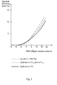
- the task may not be to maximise this expression over P. In principle, this can be carried out by exhaustive search over all 105 permutations, and computing the cost f(P) for each one. This is ineffective, and two complexity reductions to find a permutation may be considered, that may be close to optimal.
- the set of permutations that results in the standard complex-valued MMSE receiver may be denoted by In principle, contain a single element, namely ([ R 1 ,I 1 ],[ R 2 ,I 2 ];[ R 3 ,I 3 ],[ R 4 ,I 4 ]) .
- the permutation P that maximises f ( P ) is either such that there is exactly one R i that is paired with I i , or such that there is no such R i and then the optimal permutation lies within the subset P 12 .
- the two almost overlapped curves are the SUMIS algorithm with the optimal permutation taken from and respectively.
- the real SUMIS may be utilised to generate the list of candidates and thereby the generated list of candidates (hypotheses) is used for the LLR generation.
- Generating candidate vectors with the real SUMIS may start by establishing the optimal grouping/ permutation according to the previous section.
- the hardware logics for the real SUMIS may be slightly different from that of the complex-valued SUMIS. In principle it would be possible to go back into the complex domain and compute the metrics for all the ⁇ M k vectors, but that may destroy the nice structure of the real SUMIS hardware as there would be no structure in the vectors that would be known in advance. Therefore, a new hardware structure may be developed for this case.
- Exactly the same search tree as in the complex case may be reused with no modifications, the hardware is fixed and is always performing the same operations according to some embodiments.
- the preprocessing step may be changed (computing ⁇ ( ⁇ ) and ⁇ ( ⁇ , ⁇ )) and the new complexity may be about twice that of the complex case.
- ⁇ x 1 x 2 x 3 x 4 ⁇ y - HP ⁇ x 1 x 2 x 3 x 4 T ⁇ 2 , where P is the optimal permution matrix and there are M k choices for the 2x1 vector x k .
- the matrix G B1, ii is symmetric; thus the trace above may be evaluated with 3 multiplications and 2 additions under the assumption that x i ⁇ x i T is available in a LUT. In total, 5 multiplications and 4 additions may be made per ⁇ ( ⁇ ) value.
- the colour of the interference may be: w l ⁇ CN ⁇ 0 , H ⁇ l ⁇ ⁇ l ⁇ H ⁇ l H + N 0 ⁇ I , where ⁇ l is the residual variance of x l .
- Figure 4A illustrates the previously mentioned concept and steps of the hierarchical RD-MLS MIMO detector considering 4x4 MIMO set-up for simplicity.
- the embodiment related to the hierarchical RD-MLS MIMO detector may be regarded as a hybrid of the two respective previously presented detectors.
- the first two detectors may render prohibitive complexity for very large MIMO systems, e.g., to support 8 layers in 8x8 (complex-valued) MIMO system.
- this Hierarchical RD-MLS MIMO detector embodiment can also cater very large MIMO systems.
- Last but not least compute the LLRs, or soft-bits, by utilising the final list of candidates or hypotheses.
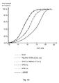
- Table 3 Cell Bandwidth 1.4 MHz Transmit EVM 6% MIMO Configuration (N R x N T ) 4x4 PDSCH Resource Allocation 6 PRB-pair Transmission Mode 3 (Open-Loop Spatial Multiplexing - OLSM Rank-4) with no fallback mode to space-frequency block coding (SFBC). Modulation and Code Rate 64QAM 0.85 Channel Model ETU 70 Low Channel and noise variance estimation Ideal knowledge HARQ Enabled Number of Subframes 1000
- LMMSE SPIC nx Reference detector namely (L)MMSE-SPIC with n iterations.
- RSUMIS RD MLS [ M 1 , M 2 , M 3 , M 4 ] It is essentially the same detector as mentioned above but without any MMSE-SPIC in the first stage.
- LMMSE Reference detector withouy any SPIC processing.
- Figure 4B shows normalised throughput versus SNR for the test case -1 setup.
- the performance of the disclosed detectors under ideal channel estimate and noise variance knowledge.
- the herein described detector embodiments outperform the linear detectors without and with SPIC, namely LMMSE and LMMSE-SPIC.
- the performance of each of these respective illustrated detectors may be as good as the optimal Maximum Likelihood detector according to some embodiments.
- Table 5 Cell Bandwidth 10 MHz Transmit EVM 6% MIMO Configuration (N R x N T ) 4x4 PDSCH Resource Allocation 50 PRB-pair Transmission Mode 3 (OLSM Rank-4) with no fallback mode to SFBC. Modulation and Code Rate 64QAM 0.85 Channel Model ETU 70 Low Channel and noise variance estimation Practical, 2x1D LMMSE, and ideal for LMMSE reference detector HARQ Enabled Number of Subframes 1000
- Figure 4C illustrates the performance of the disclosed detectors considering channel estimation error variance knowledge. As expected, the performance of RD-MLS can be improved significantly over the channel estimation error unaware detector.
- Table 7 Cell Bandwidth 1.4 MHz Transmit EVM 6% MIMO Configuration (N R x N T ) 4x4 PDSCH Resource Allocation 6 PRB-pair Transmission Mode 3 (OLSM Rank-4) with no fallback mode to SFBC. Modulation and Code Rate 16QAM 0.72 Channel Model ETU 300 Low Channel and noise variance estimation Ideal knowledge HARQ Enabled Number of Subframes 1000
- the performance of the detector embodiment is shown in Figure 4D and the corresponding legends in the figure are defined in Table 8.
- the performance of the described low-complexity detector, particularly RSUMIS aided RD-MLS is as good as the optimal detector in maximum-likelihood sense, namely MLM.
- Figure 4D illustrates normalised throughput versus SNR for the test case -3 set-up.
- Table 8 MLM Maximum Likelihood detector and the soft bits are computed based on the max-log-MAP criterion.
- RSUMIS RD MLS [ M 1 , M 2 , M 3 , M 4 ]
- it is real-valued SUMIS aided RD-MLS detector with pre-defined number of candidates per spatial layer.
- SPIC nx RD MLS [ M 1 , M 2 , M 3 , M 4 ] MMSE-SPIC aided RD-MLS with n demodulator iterations and with pre-defined number of candidates per spatial layer.
- some embodiments disclosed herein relates to efficient computation of the metrics for the remaining candidate vectors.
- Methods disclosed herein provide further reduction of the number of candidate vectors.
- methods for efficient computations of the metrics for remaining candidate vectors within a real valued framework are disclosed.
- methods of using self-iterated Soft-Parallel Interference Cancellations (SPIC) as an initialization step to generate a set of candidate vectors are disclosed.
- SPIC Soft-Parallel Interference Cancellations
- a method of using self-iterated real-SUMIS, with and without SPIC as an initialisation step to generate a set of candidate vectors are disclosed.
- methods of incorporating knowledge of channel estimation errors into the disclosed art detectors are disclosed.
- hierarchical detectors for an arbitrary number of transmission layers are disclosed.
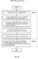
- FIG. 5 is a flow chart illustrating embodiments of a method 500 in a User Equipment (UE) 120.
- the method 500 aims at providing Multiple-Input and Multiple-Output (MIMO) detection of signals received from a radio network node 110, comprised in a wireless communication network 100.
- MIMO Multiple-Input and Multiple-Output
- the radio network node 110 may comprise an evolved NodeB (eNodeB).
- the wireless communication network 100 may be based on 3rd Generation Partnership Project Long Term Evolution (3GPP LTE), such as e.g. LTE-Advanced. Further, the wireless communication system 100 may be based on Frequency Division Duplex (FDD) and/ or Time Division Duplex (TDD) in different embodiments.
- 3GPP LTE 3rd Generation Partnership Project Long Term Evolution
- LTE-Advanced 3rd Generation Partnership Project Long Term Evolution
- FDD Frequency Division Duplex
- TDD Time Division Duplex
- the method 500 may comprise a number of actions 501-511.
- any, some or all of the described actions 501-511 may be performed in a somewhat different chronological order than the enumeration indicates, be performed simultaneously or even be performed in a completely reversed order according to different embodiments. Some actions may be performed within some alternative embodiments such as e.g. actions 502-509. Further, it is to be noted that some actions may be performed in a plurality of alternative manners according to different embodiments, and that some such alternative manners may be performed only within some, but not necessarily all embodiments.
- the method 500 may comprise the following actions:
- a signal of the radio network node 110 is received.
- This action may be performed within some, but not all embodiments.
- a Linear Minimum Mean Square Error (LMMSE) estimate of the transmitted modulation alphabet may be computed via the received 501 signal.
- LMMSE Linear Minimum Mean Square Error
- the computation of the LMMSE may in some embodiments be made on a complex- valued received 501 signal.
- knowledge about errors in channel estimation may be utilised for computing path metrics of the hypotheses candidate vector.
- This action may be performed within some, but not all embodiments.
- Soft parallel interference cancellation may be performed, with MMSE of the received 501 signal on a given number of iterations.
- the performance of the soft parallel interference cancellation may in some embodiments comprise MMSE filtering on a complex- valued received 501 signal.
- This action may be performed within some, but not all embodiments.
- the most likely candidates per spatial layer may be calculated independently for each layer, in some embodiments.
- the LLRs from the first stage processing may be utilised, which is LMMSE/ MMSE-SPIC demodulation.
- a candidate reduction technique may be utilised in order to reduce the list of hypotheses candidate vector by pruning the most unlikely candidates' combinations forming the hypotheses.
- This action may be performed within some, but not all embodiments.
- the complex-valued received 501 signal may be converted into real-valued; and thereby obtaining four 2x2 real-valued groups by utilising Subspace Marginalisation Interference Suppression (SUMIS) algorithm.
- SUMIS Subspace Marginalisation Interference Suppression
- This action may be performed within some, but not all embodiments where action 505 has been performed.
- a set of most likely candidates for each 2x2 real-valued groups may be obtained, after having a set of most likely candidates for each group, and forming a list of all possible hypotheses candidate vector based on the candidates found in 2x2 reak-valued groups.
- This action may be performed within some, but not all embodiments.
- 2x2 complex-valued smaller MIMO groups may be established by utilising SUMIS algorithm.
- This action may be performed within some, but not all embodiments where action 507 has been performed.
- the most likely set of candidates may be searched jointly in each 2x2 MIMO group.
- This action may be performed within some, but not all embodiments, where any of action 507 and/ or 508 has been performed.
- the hypotheses candidate vector may be obtained by establishing all the possible combinations of the likely candidates obtained for each smaller 2x2 MIMO groups.
- a list of hypotheses candidate vector is established.
- the list of hypotheses candidate vector may in some embodiments be established based on possible combinations of the calculated 504 most likely candidates per spatial layer.
- Path metrics of the established 510 list of hypotheses candidate vector is computed; thereby computing Log-Likelihood Ratios (LLRs) utilising the computed path metrics for achieving MIMO detection.
- LLRs Log-Likelihood Ratios
- the computed path metrics of the established 510 list of hypotheses candidate vector may in some embodiments be evaluated recursively over a tree structure.
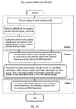
- FIG. 6 illustrates an embodiment of a User Equipment (UE) 120.
- the UE 120 is configured for performing at least some of the previously described method actions 501-511, for MIMO detection of signals received from a radio network node 110, comprised in a wireless communication network 100.
- the radio network node 110 may comprise an evolved NodeB (eNodeB).
- the wireless communication network 100 may be based on 3rd Generation Partnership Project Long Term Evolution (3GPP LTE), such as LTE- Advanced. Further, the wireless communication system 100 may be based on FDD or TDD in different embodiments.
- 3GPP LTE 3rd Generation Partnership Project Long Term Evolution
- the UE 120 comprises a receiving circuit 610, configured for receiving signals from the radio network node 110.
- Such receiving circuit 610 in the UE 120 may be configured for receiving wireless signals from the radio network node 110 or any other entity configured for wireless communication over a wireless interface according to some embodiments.
- the UE 120 also comprises a processing circuit 620, configured for establishing a list of hypotheses candidate vector. Also, the processing circuit 620 is also configured for computing path metrics of the established list of hypotheses candidate vector by computing Log-Likelihood Ratios (LLR) utilising the computed path metrics for achieving MIMO detection.
- LLR Log-Likelihood Ratios
- the processing circuit 620 may furthermore be configured for Linear Minimum Mean Square Error (LMMSE) estimate of transmitted modulation alphabet via the received signal.
- LMMSE Linear Minimum Mean Square Error
- processing circuit 620 may further be configured for computing LMMSE on a complex- valued received signal.
- the processing circuit 620 may further, in some embodiments be configured for performing soft parallel interference cancellation with MMSE of the received signal on a given number of iterations.
- processing circuit 620 may be further configured for performing the soft parallel interference cancellation comprises MMSE filtering on a complex- valued received signal.
- processing circuit 620 may further be configured for calculating the most likely candidates per spatial layer independently for each layer, according to some embodiments.
- the processing circuit 620 may be further configured for establishing the list of hypotheses candidate vector, based on possible combinations of the calculated most likely candidates per spatial layer.
- processing circuit 620 may furthermore be configured for converting complex-valued received signal into real-valued; and thereby obtaining four 2x2 real-valued groups by utilising Subspace Marginalisation Interference Suppression (SUMIS) algorithm.
- SUMIS Subspace Marginalisation Interference Suppression
- the processing circuit 620 may further be additionally configured for also obtaining a set of most likely candidates for each 2x2 real-valued groups, after having a set of most likely candidates for each group, and forming a list of all possible hypotheses candidate vector based on the candidates found in 2x2 real-valued groups, in some embodiments.
- the processing circuit 620 may in some embodiments be further configured for utilising the LLRs from the first stage processing.
- processing circuit 620 may be furthermore configured for computing LMMSE of the received signal by utilising knowledge about errors in channel estimation.
- the processing circuit 620 may be further configured, in some embodiments, for utilising a candidate reduction technique in order to reduce the number of candidates before calculating the most likely candidates per spatial layer independently for each layer.
- the processing circuit 620 may furthermore be configured for computing path metrics of the established list of hypotheses candidate vector, evaluated recursively over a tree structure.
- the processing circuit 620 may be further configured for reducing the number of additions such that: a depth 4 matrix requires 2 M 4 M 3 M 2 M 1 + M 4 M 2 M 1 + M 4 M 1 real additions; a depth 3 matrix requires 2 M 3 M 2 M 1 + M 3 M 1 real additions; a depth 2 matrix requires 2 M 2 M 1 real additions.
- processing circuit 620 may comprise one or more instances of a processor, i.e. a Central Processing Unit (CPU), a processing unit, a processing circuit, an Application Specific Integrated Circuit (ASIC), a microprocessor, or other processing logic that may interpret and execute instructions.
- a processor i.e. a Central Processing Unit (CPU), a processing unit, a processing circuit, an Application Specific Integrated Circuit (ASIC), a microprocessor, or other processing logic that may interpret and execute instructions.
- CPU Central Processing Unit
- ASIC Application Specific Integrated Circuit
- microprocessor or other processing logic that may interpret and execute instructions.
- the herein utilised expression "processing circuit” may thus represent a processing circuitry comprising a plurality of processing circuits, such as, e.g., any, some or all of the ones enumerated above.
- the UE 120 may in some embodiments also comprise at least one memory 625 in the UE 120.
- the optional memory 625 may comprise a physical device utilised to store data or programs, i.e., sequences of instructions, on a temporary or permanent basis.
- the memory 625 may comprise integrated circuits comprising silicon-based transistors. Further, the memory 625 may be volatile or non-volatile.
- the UE 120 furthermore may comprise a transmitting circuit 630, which may be configured for transmitting wireless signals according to some embodiments.
- the UE 120 and/ or the processing circuit 620 may comprise an establishing unit, configured for establishing a list of hypotheses candidate vector. Also, the UE 120 and/ or the processing circuit 620 may comprise a computing unit, configured for computing path metrics of the established list of hypotheses candidate vector, and thereby computing LLRs utilising the computed path metrics for achieving MIMO detection.
- the actions 501-511 to be performed in the UE 120 may be implemented through the one or more processing circuits 620 in the UE 120 together with computer program product for performing the functions of the actions 501-511.
- a computer program product comprising program code for performing the method 500 according to any of actions 501-511, for MIMO detection of signals received from a radio network node 110 according to any of the actions 501-511, when the computer program product is loaded in a processing circuit 620 of the UE 120.
- the computer program product may comprise a computer readable storage medium storing program code thereon for MIMO detection of signals received from a radio network node 110, comprised in a wireless communication network 100, by performing a method 500 comprising: receiving 501 a signal of the radio network node 110; establishing 510 a list of hypotheses candidate vector; and computing 511 path metrics of the established 510 list of hypotheses candidate vector, and thereby computing LLRs utilising the computed path metrics for achieving MIMO detection.
- the computer program product mentioned above may be provided for instance in the form of a data carrier carrying computer program code for performing at least some of the actions 501-511 according to some embodiments when being loaded into the processing circuit 620 comprised in the UE 120.
- the data carrier may be, e.g., a hard disk, a CD ROM disc, a memory stick, an optical storage device, a magnetic storage device or any other appropriate medium such as a disk or tape that may hold machine readable data in a non transitory manner.
- the computer program product may furthermore be provided as computer program code on a server and downloaded to the UE 120, e.g., over an Internet or an intranet connection.
- the term “and/ or” comprises any and all combinations of one or more of the associated listed items.
- the singular forms “a”, “an” and “the” are to be interpreted as “at least one”, thus also possibly comprising a plurality of entities of the same kind, unless expressly stated otherwise.
- the terms “includes”, “comprises”, “including” and/ or “comprising” specifies the presence of stated features, actions, integers, steps, operations, elements, and/ or components, but do not preclude the presence or addition of one or more other features, actions, integers, steps, operations, elements, components, and/ or groups thereof.
- a single unit such as e.g.
- a processing circuit 620 may fulfil the functions of several items recited in the claims.
- a computer program may be stored/ distributed on a suitable medium, such as an optical storage medium or a solid-state medium supplied together with or as part of other hardware, but may also be distributed in other forms such as via Internet or other wired or wireless communication system.
Landscapes
- Physics & Mathematics (AREA)
- Mathematical Physics (AREA)
- Engineering & Computer Science (AREA)
- Computer Networks & Wireless Communication (AREA)
- Signal Processing (AREA)
- Radio Transmission System (AREA)
- Mobile Radio Communication Systems (AREA)
Priority Applications (2)
| Application Number | Priority Date | Filing Date | Title |
|---|---|---|---|
| EP13193971.2A EP2876820B1 (de) | 2013-11-22 | 2013-11-22 | Verfahren und Knoten in einem drahtlosen Kommunikationssystem |
| CN201410004099.2A CN103840918B (zh) | 2013-11-22 | 2014-01-02 | 无线通信系统中的方法和节点 |
Applications Claiming Priority (1)
| Application Number | Priority Date | Filing Date | Title |
|---|---|---|---|
| EP13193971.2A EP2876820B1 (de) | 2013-11-22 | 2013-11-22 | Verfahren und Knoten in einem drahtlosen Kommunikationssystem |
Publications (2)
| Publication Number | Publication Date |
|---|---|
| EP2876820A1 true EP2876820A1 (de) | 2015-05-27 |
| EP2876820B1 EP2876820B1 (de) | 2017-11-08 |
Family
ID=49641610
Family Applications (1)
| Application Number | Title | Priority Date | Filing Date |
|---|---|---|---|
| EP13193971.2A Active EP2876820B1 (de) | 2013-11-22 | 2013-11-22 | Verfahren und Knoten in einem drahtlosen Kommunikationssystem |
Country Status (2)
| Country | Link |
|---|---|
| EP (1) | EP2876820B1 (de) |
| CN (1) | CN103840918B (de) |
Cited By (1)
| Publication number | Priority date | Publication date | Assignee | Title |
|---|---|---|---|---|
| WO2021146975A1 (en) | 2020-01-22 | 2021-07-29 | Nokia Shanghai Bell Co., Ltd | Soft-decision information generation for receiver |
Families Citing this family (2)
| Publication number | Priority date | Publication date | Assignee | Title |
|---|---|---|---|---|
| CN110063046A (zh) * | 2016-06-08 | 2019-07-26 | 华为技术有限公司 | 接收设备及其方法 |
| CN108847886A (zh) * | 2018-05-25 | 2018-11-20 | 复旦大学 | 一种空分复用方式的信号传输方法 |
Citations (3)
| Publication number | Priority date | Publication date | Assignee | Title |
|---|---|---|---|---|
| US20080069262A1 (en) * | 2006-09-19 | 2008-03-20 | Nec Laboratories America, Inc. | Enhanced Successive Interference Cancellation (SIC) Receiver for Multiple-Input Multiple-Output (MIMO) Systems |
| US20120219097A1 (en) * | 2011-02-24 | 2012-08-30 | Qualcomm Incorporated | Two-step joint demapping algorithm for llr computation of mimo signal based on sphere decoding |
| US8559543B1 (en) * | 2009-10-09 | 2013-10-15 | Marvell International Ltd. | Soft sphere decoder for MIMO maximum likelihood demodulation |
Family Cites Families (3)
| Publication number | Priority date | Publication date | Assignee | Title |
|---|---|---|---|---|
| CN100505713C (zh) * | 2005-10-26 | 2009-06-24 | 电子科技大学 | 一种低复杂度的多入多出迭代检测方法 |
| CN101442390A (zh) * | 2007-11-19 | 2009-05-27 | 电子科技大学 | 空间相关MIMO的Turbo均衡接收方法与装置 |
| CN102412931A (zh) * | 2011-11-17 | 2012-04-11 | 信源通科技(西安)有限公司 | 多天线比特交织编码系统的串行干扰抵消检测方法及系统 |
-
2013
- 2013-11-22 EP EP13193971.2A patent/EP2876820B1/de active Active
-
2014
- 2014-01-02 CN CN201410004099.2A patent/CN103840918B/zh active Active
Patent Citations (3)
| Publication number | Priority date | Publication date | Assignee | Title |
|---|---|---|---|---|
| US20080069262A1 (en) * | 2006-09-19 | 2008-03-20 | Nec Laboratories America, Inc. | Enhanced Successive Interference Cancellation (SIC) Receiver for Multiple-Input Multiple-Output (MIMO) Systems |
| US8559543B1 (en) * | 2009-10-09 | 2013-10-15 | Marvell International Ltd. | Soft sphere decoder for MIMO maximum likelihood demodulation |
| US20120219097A1 (en) * | 2011-02-24 | 2012-08-30 | Qualcomm Incorporated | Two-step joint demapping algorithm for llr computation of mimo signal based on sphere decoding |
Cited By (3)
| Publication number | Priority date | Publication date | Assignee | Title |
|---|---|---|---|---|
| WO2021146975A1 (en) | 2020-01-22 | 2021-07-29 | Nokia Shanghai Bell Co., Ltd | Soft-decision information generation for receiver |
| EP4094412A4 (de) * | 2020-01-22 | 2023-10-11 | Nokia Solutions and Networks Oy | Soft-decision-informations-generierung für empfänger |
| US11956105B2 (en) | 2020-01-22 | 2024-04-09 | Nokia Solutions And Networks Oy | Soft-decision information generation for receiver |
Also Published As
| Publication number | Publication date |
|---|---|
| EP2876820B1 (de) | 2017-11-08 |
| CN103840918A (zh) | 2014-06-04 |
| CN103840918B (zh) | 2017-09-29 |
Similar Documents
| Publication | Publication Date | Title |
|---|---|---|
| EP1905182B1 (de) | Verfahren und vorrichtung zur erfassung von kommunikation aus mehreren quellen | |
| CN102835055A (zh) | 用于多输入多输出(mimo)通信系统中的迭代解码的方法和装置 | |
| EP2883336B1 (de) | Gestapelte und verzweigte vamos-empfänger mit sukzessiver interferenzunterdrückung | |
| US8542781B2 (en) | Incrementally inclusive frequency domain symbol joint detection | |
| US10819468B2 (en) | Stochastic linear detection | |
| EP3169028B1 (de) | Halb-abschliessendes rekursives blockdecodierungsverfahren und vorrichtung | |
| Knievel et al. | Multi-dimensional graph-based soft iterative receiver for MIMO-OFDM | |
| Wiesmayr et al. | DUIDD: Deep-unfolded interleaved detection and decoding for MIMO wireless systems | |
| CN115668854A (zh) | 基于递归树搜索的多进多出检测装置及方法 | |
| US9118446B2 (en) | Methods and user equipment in a wireless communication network | |
| US20150146546A1 (en) | Method and nodes in a wireless communication system | |
| EP2876820B1 (de) | Verfahren und Knoten in einem drahtlosen Kommunikationssystem | |
| Hu et al. | A soft-output MIMO detector with achievable information rate based partial marginalization | |
| Wu et al. | Iterative detection and decoding in 3GPP LTE-based massive MIMO systems | |
| Narasimhan et al. | Channel hardening-exploiting message passing (CHEMP) receiver in large MIMO systems | |
| Manchón et al. | Receiver architectures for MIMO-OFDM based on a combined VMP-SP algorithm | |
| Chen et al. | Turbo AI, Part V: Verifying AI-Enhanced Channel Estimation for RAN from System Level | |
| Ketonen et al. | MIMO detection in single carrier systems | |
| Hu | Channel shortening in wireless communication | |
| WO2012122778A1 (en) | System and method for signaling and detecting in wireless communications systems | |
| EP2852080B1 (de) | Verfahren und Benutzergerät in einem drahtlosen Kommunikationsnetzwerk | |
| Hui et al. | MIMO detection techniques based on low complexity adaptive QR-decomposition with M-algorithm for 3GPP LTE systems | |
| Jakubisin et al. | Probabilistic receiver architecture combining BP, MF, and EP for multi-signal detection | |
| Namboodiri et al. | Successive interference cancelation and MAP decoding for mobile MIMO OFDM systems and their convergence behavior | |
| Tian et al. | Gaussian message passing based receiver for multicarrier faster-than-Nyquist signaling |
Legal Events
| Date | Code | Title | Description |
|---|---|---|---|
| PUAI | Public reference made under article 153(3) epc to a published international application that has entered the european phase |
Free format text: ORIGINAL CODE: 0009012 |
|
| 17P | Request for examination filed |
Effective date: 20131122 |
|
| AK | Designated contracting states |
Kind code of ref document: A1 Designated state(s): AL AT BE BG CH CY CZ DE DK EE ES FI FR GB GR HR HU IE IS IT LI LT LU LV MC MK MT NL NO PL PT RO RS SE SI SK SM TR |
|
| AX | Request for extension of the european patent |
Extension state: BA ME |
|
| GRAP | Despatch of communication of intention to grant a patent |
Free format text: ORIGINAL CODE: EPIDOSNIGR1 |
|
| STAA | Information on the status of an ep patent application or granted ep patent |
Free format text: STATUS: GRANT OF PATENT IS INTENDED |
|
| INTG | Intention to grant announced |
Effective date: 20170526 |
|
| GRAS | Grant fee paid |
Free format text: ORIGINAL CODE: EPIDOSNIGR3 |
|
| GRAA | (expected) grant |
Free format text: ORIGINAL CODE: 0009210 |
|
| STAA | Information on the status of an ep patent application or granted ep patent |
Free format text: STATUS: THE PATENT HAS BEEN GRANTED |
|
| AK | Designated contracting states |
Kind code of ref document: B1 Designated state(s): AL AT BE BG CH CY CZ DE DK EE ES FI FR GB GR HR HU IE IS IT LI LT LU LV MC MK MT NL NO PL PT RO RS SE SI SK SM TR |
|
| REG | Reference to a national code |
Ref country code: GB Ref legal event code: FG4D |
|
| REG | Reference to a national code |
Ref country code: FR Ref legal event code: PLFP Year of fee payment: 5 |
|
| REG | Reference to a national code |
Ref country code: CH Ref legal event code: EP Ref country code: AT Ref legal event code: REF Ref document number: 945099 Country of ref document: AT Kind code of ref document: T Effective date: 20171115 |
|
| REG | Reference to a national code |
Ref country code: IE Ref legal event code: FG4D |
|
| REG | Reference to a national code |
Ref country code: DE Ref legal event code: R096 Ref document number: 602013029038 Country of ref document: DE |
|
| REG | Reference to a national code |
Ref country code: NL Ref legal event code: MP Effective date: 20171108 |
|
| REG | Reference to a national code |
Ref country code: LT Ref legal event code: MG4D |
|
| REG | Reference to a national code |
Ref country code: AT Ref legal event code: MK05 Ref document number: 945099 Country of ref document: AT Kind code of ref document: T Effective date: 20171108 |
|
| PG25 | Lapsed in a contracting state [announced via postgrant information from national office to epo] |
Ref country code: NL Free format text: LAPSE BECAUSE OF FAILURE TO SUBMIT A TRANSLATION OF THE DESCRIPTION OR TO PAY THE FEE WITHIN THE PRESCRIBED TIME-LIMIT Effective date: 20171108 Ref country code: FI Free format text: LAPSE BECAUSE OF FAILURE TO SUBMIT A TRANSLATION OF THE DESCRIPTION OR TO PAY THE FEE WITHIN THE PRESCRIBED TIME-LIMIT Effective date: 20171108 Ref country code: NO Free format text: LAPSE BECAUSE OF FAILURE TO SUBMIT A TRANSLATION OF THE DESCRIPTION OR TO PAY THE FEE WITHIN THE PRESCRIBED TIME-LIMIT Effective date: 20180208 Ref country code: ES Free format text: LAPSE BECAUSE OF FAILURE TO SUBMIT A TRANSLATION OF THE DESCRIPTION OR TO PAY THE FEE WITHIN THE PRESCRIBED TIME-LIMIT Effective date: 20171108 Ref country code: SE Free format text: LAPSE BECAUSE OF FAILURE TO SUBMIT A TRANSLATION OF THE DESCRIPTION OR TO PAY THE FEE WITHIN THE PRESCRIBED TIME-LIMIT Effective date: 20171108 Ref country code: LT Free format text: LAPSE BECAUSE OF FAILURE TO SUBMIT A TRANSLATION OF THE DESCRIPTION OR TO PAY THE FEE WITHIN THE PRESCRIBED TIME-LIMIT Effective date: 20171108 |
|
| PG25 | Lapsed in a contracting state [announced via postgrant information from national office to epo] |
Ref country code: GR Free format text: LAPSE BECAUSE OF FAILURE TO SUBMIT A TRANSLATION OF THE DESCRIPTION OR TO PAY THE FEE WITHIN THE PRESCRIBED TIME-LIMIT Effective date: 20180209 Ref country code: AT Free format text: LAPSE BECAUSE OF FAILURE TO SUBMIT A TRANSLATION OF THE DESCRIPTION OR TO PAY THE FEE WITHIN THE PRESCRIBED TIME-LIMIT Effective date: 20171108 Ref country code: IS Free format text: LAPSE BECAUSE OF FAILURE TO SUBMIT A TRANSLATION OF THE DESCRIPTION OR TO PAY THE FEE WITHIN THE PRESCRIBED TIME-LIMIT Effective date: 20180308 Ref country code: LV Free format text: LAPSE BECAUSE OF FAILURE TO SUBMIT A TRANSLATION OF THE DESCRIPTION OR TO PAY THE FEE WITHIN THE PRESCRIBED TIME-LIMIT Effective date: 20171108 Ref country code: BG Free format text: LAPSE BECAUSE OF FAILURE TO SUBMIT A TRANSLATION OF THE DESCRIPTION OR TO PAY THE FEE WITHIN THE PRESCRIBED TIME-LIMIT Effective date: 20180208 Ref country code: RS Free format text: LAPSE BECAUSE OF FAILURE TO SUBMIT A TRANSLATION OF THE DESCRIPTION OR TO PAY THE FEE WITHIN THE PRESCRIBED TIME-LIMIT Effective date: 20171108 Ref country code: HR Free format text: LAPSE BECAUSE OF FAILURE TO SUBMIT A TRANSLATION OF THE DESCRIPTION OR TO PAY THE FEE WITHIN THE PRESCRIBED TIME-LIMIT Effective date: 20171108 |
|
| PG25 | Lapsed in a contracting state [announced via postgrant information from national office to epo] |
Ref country code: CZ Free format text: LAPSE BECAUSE OF FAILURE TO SUBMIT A TRANSLATION OF THE DESCRIPTION OR TO PAY THE FEE WITHIN THE PRESCRIBED TIME-LIMIT Effective date: 20171108 Ref country code: CH Free format text: LAPSE BECAUSE OF NON-PAYMENT OF DUE FEES Effective date: 20171130 Ref country code: LI Free format text: LAPSE BECAUSE OF NON-PAYMENT OF DUE FEES Effective date: 20171130 Ref country code: SK Free format text: LAPSE BECAUSE OF FAILURE TO SUBMIT A TRANSLATION OF THE DESCRIPTION OR TO PAY THE FEE WITHIN THE PRESCRIBED TIME-LIMIT Effective date: 20171108 Ref country code: DK Free format text: LAPSE BECAUSE OF FAILURE TO SUBMIT A TRANSLATION OF THE DESCRIPTION OR TO PAY THE FEE WITHIN THE PRESCRIBED TIME-LIMIT Effective date: 20171108 Ref country code: EE Free format text: LAPSE BECAUSE OF FAILURE TO SUBMIT A TRANSLATION OF THE DESCRIPTION OR TO PAY THE FEE WITHIN THE PRESCRIBED TIME-LIMIT Effective date: 20171108 Ref country code: CY Free format text: LAPSE BECAUSE OF FAILURE TO SUBMIT A TRANSLATION OF THE DESCRIPTION OR TO PAY THE FEE WITHIN THE PRESCRIBED TIME-LIMIT Effective date: 20171108 |
|
| REG | Reference to a national code |
Ref country code: DE Ref legal event code: R097 Ref document number: 602013029038 Country of ref document: DE |
|
| PG25 | Lapsed in a contracting state [announced via postgrant information from national office to epo] |
Ref country code: RO Free format text: LAPSE BECAUSE OF FAILURE TO SUBMIT A TRANSLATION OF THE DESCRIPTION OR TO PAY THE FEE WITHIN THE PRESCRIBED TIME-LIMIT Effective date: 20171108 Ref country code: IT Free format text: LAPSE BECAUSE OF FAILURE TO SUBMIT A TRANSLATION OF THE DESCRIPTION OR TO PAY THE FEE WITHIN THE PRESCRIBED TIME-LIMIT Effective date: 20171108 Ref country code: PL Free format text: LAPSE BECAUSE OF FAILURE TO SUBMIT A TRANSLATION OF THE DESCRIPTION OR TO PAY THE FEE WITHIN THE PRESCRIBED TIME-LIMIT Effective date: 20171108 Ref country code: LU Free format text: LAPSE BECAUSE OF NON-PAYMENT OF DUE FEES Effective date: 20171122 Ref country code: SM Free format text: LAPSE BECAUSE OF FAILURE TO SUBMIT A TRANSLATION OF THE DESCRIPTION OR TO PAY THE FEE WITHIN THE PRESCRIBED TIME-LIMIT Effective date: 20171108 |
|
| REG | Reference to a national code |
Ref country code: BE Ref legal event code: MM Effective date: 20171130 |
|
| REG | Reference to a national code |
Ref country code: IE Ref legal event code: MM4A |
|
| PLBE | No opposition filed within time limit |
Free format text: ORIGINAL CODE: 0009261 |
|
| STAA | Information on the status of an ep patent application or granted ep patent |
Free format text: STATUS: NO OPPOSITION FILED WITHIN TIME LIMIT |
|
| PG25 | Lapsed in a contracting state [announced via postgrant information from national office to epo] |
Ref country code: MT Free format text: LAPSE BECAUSE OF NON-PAYMENT OF DUE FEES Effective date: 20171122 |
|
| REG | Reference to a national code |
Ref country code: FR Ref legal event code: PLFP Year of fee payment: 6 |
|
| 26N | No opposition filed |
Effective date: 20180809 |
|
| PG25 | Lapsed in a contracting state [announced via postgrant information from national office to epo] |
Ref country code: IE Free format text: LAPSE BECAUSE OF NON-PAYMENT OF DUE FEES Effective date: 20171122 |
|
| PG25 | Lapsed in a contracting state [announced via postgrant information from national office to epo] |
Ref country code: SI Free format text: LAPSE BECAUSE OF FAILURE TO SUBMIT A TRANSLATION OF THE DESCRIPTION OR TO PAY THE FEE WITHIN THE PRESCRIBED TIME-LIMIT Effective date: 20171108 Ref country code: BE Free format text: LAPSE BECAUSE OF NON-PAYMENT OF DUE FEES Effective date: 20171130 |
|
| PG25 | Lapsed in a contracting state [announced via postgrant information from national office to epo] |
Ref country code: MC Free format text: LAPSE BECAUSE OF FAILURE TO SUBMIT A TRANSLATION OF THE DESCRIPTION OR TO PAY THE FEE WITHIN THE PRESCRIBED TIME-LIMIT Effective date: 20171108 Ref country code: HU Free format text: LAPSE BECAUSE OF FAILURE TO SUBMIT A TRANSLATION OF THE DESCRIPTION OR TO PAY THE FEE WITHIN THE PRESCRIBED TIME-LIMIT; INVALID AB INITIO Effective date: 20131122 |
|
| PG25 | Lapsed in a contracting state [announced via postgrant information from national office to epo] |
Ref country code: MK Free format text: LAPSE BECAUSE OF FAILURE TO SUBMIT A TRANSLATION OF THE DESCRIPTION OR TO PAY THE FEE WITHIN THE PRESCRIBED TIME-LIMIT Effective date: 20171108 |
|
| PG25 | Lapsed in a contracting state [announced via postgrant information from national office to epo] |
Ref country code: TR Free format text: LAPSE BECAUSE OF FAILURE TO SUBMIT A TRANSLATION OF THE DESCRIPTION OR TO PAY THE FEE WITHIN THE PRESCRIBED TIME-LIMIT Effective date: 20171108 |
|
| PG25 | Lapsed in a contracting state [announced via postgrant information from national office to epo] |
Ref country code: PT Free format text: LAPSE BECAUSE OF FAILURE TO SUBMIT A TRANSLATION OF THE DESCRIPTION OR TO PAY THE FEE WITHIN THE PRESCRIBED TIME-LIMIT Effective date: 20171108 |
|
| PG25 | Lapsed in a contracting state [announced via postgrant information from national office to epo] |
Ref country code: AL Free format text: LAPSE BECAUSE OF FAILURE TO SUBMIT A TRANSLATION OF THE DESCRIPTION OR TO PAY THE FEE WITHIN THE PRESCRIBED TIME-LIMIT Effective date: 20171108 |
|
| REG | Reference to a national code |
Ref country code: DE Ref legal event code: R081 Ref document number: 602013029038 Country of ref document: DE Owner name: HONOR DEVICE CO., LTD., SHENZHEN, CN Free format text: FORMER OWNER: HUAWEI TECHNOLOGIES CO., LTD., SHEN ZHEN, GUANGDONG, CN |
|
| REG | Reference to a national code |
Ref country code: GB Ref legal event code: 732E Free format text: REGISTERED BETWEEN 20210812 AND 20210818 |
|
| PGFP | Annual fee paid to national office [announced via postgrant information from national office to epo] |
Ref country code: DE Payment date: 20241001 Year of fee payment: 12 |
|
| PGFP | Annual fee paid to national office [announced via postgrant information from national office to epo] |
Ref country code: GB Payment date: 20241001 Year of fee payment: 12 |
|
| PGFP | Annual fee paid to national office [announced via postgrant information from national office to epo] |
Ref country code: FR Payment date: 20241001 Year of fee payment: 12 |