EP2876876A2 - Bildprojektionsvorrichtung, Bildprojektionsverfahren und computerlesbares Speichermedium - Google Patents
Bildprojektionsvorrichtung, Bildprojektionsverfahren und computerlesbares Speichermedium Download PDFInfo
- Publication number
- EP2876876A2 EP2876876A2 EP14194117.9A EP14194117A EP2876876A2 EP 2876876 A2 EP2876876 A2 EP 2876876A2 EP 14194117 A EP14194117 A EP 14194117A EP 2876876 A2 EP2876876 A2 EP 2876876A2
- Authority
- EP
- European Patent Office
- Prior art keywords
- image
- projection
- distortion
- corrected
- captured image
- Prior art date
- Legal status (The legal status is an assumption and is not a legal conclusion. Google has not performed a legal analysis and makes no representation as to the accuracy of the status listed.)
- Withdrawn
Links
- 238000000034 method Methods 0.000 title claims description 16
- 238000003384 imaging method Methods 0.000 claims abstract description 38
- 239000002131 composite material Substances 0.000 claims description 18
- 230000003287 optical effect Effects 0.000 description 26
- 238000012545 processing Methods 0.000 description 22
- 230000001133 acceleration Effects 0.000 description 11
- 238000012937 correction Methods 0.000 description 6
- 238000010586 diagram Methods 0.000 description 6
- 238000005259 measurement Methods 0.000 description 5
- 230000008901 benefit Effects 0.000 description 3
- 238000005286 illumination Methods 0.000 description 3
- 238000009434 installation Methods 0.000 description 3
- 150000001875 compounds Chemical class 0.000 description 2
- 238000007796 conventional method Methods 0.000 description 2
- 230000004048 modification Effects 0.000 description 2
- 238000012986 modification Methods 0.000 description 2
- 230000008569 process Effects 0.000 description 2
- 230000015556 catabolic process Effects 0.000 description 1
- 230000008859 change Effects 0.000 description 1
- 230000006835 compression Effects 0.000 description 1
- 238000007906 compression Methods 0.000 description 1
- 238000010276 construction Methods 0.000 description 1
- 238000006731 degradation reaction Methods 0.000 description 1
- 230000000694 effects Effects 0.000 description 1
- 238000005516 engineering process Methods 0.000 description 1
- 230000006870 function Effects 0.000 description 1
- 239000004973 liquid crystal related substance Substances 0.000 description 1
- 239000011159 matrix material Substances 0.000 description 1
- 230000009466 transformation Effects 0.000 description 1
Images


Classifications
-
- H—ELECTRICITY
- H04—ELECTRIC COMMUNICATION TECHNIQUE
- H04N—PICTORIAL COMMUNICATION, e.g. TELEVISION
- H04N9/00—Details of colour television systems
- H04N9/12—Picture reproducers
- H04N9/31—Projection devices for colour picture display, e.g. using electronic spatial light modulators [ESLM]
- H04N9/3179—Video signal processing therefor
- H04N9/3185—Geometric adjustment, e.g. keystone or convergence
-
- H—ELECTRICITY
- H04—ELECTRIC COMMUNICATION TECHNIQUE
- H04N—PICTORIAL COMMUNICATION, e.g. TELEVISION
- H04N5/00—Details of television systems
- H04N5/222—Studio circuitry; Studio devices; Studio equipment
- H04N5/262—Studio circuits, e.g. for mixing, switching-over, change of character of image, other special effects ; Cameras specially adapted for the electronic generation of special effects
- H04N5/265—Mixing
-
- G—PHYSICS
- G03—PHOTOGRAPHY; CINEMATOGRAPHY; ANALOGOUS TECHNIQUES USING WAVES OTHER THAN OPTICAL WAVES; ELECTROGRAPHY; HOLOGRAPHY
- G03B—APPARATUS OR ARRANGEMENTS FOR TAKING PHOTOGRAPHS OR FOR PROJECTING OR VIEWING THEM; APPARATUS OR ARRANGEMENTS EMPLOYING ANALOGOUS TECHNIQUES USING WAVES OTHER THAN OPTICAL WAVES; ACCESSORIES THEREFOR
- G03B17/00—Details of cameras or camera bodies; Accessories therefor
- G03B17/48—Details of cameras or camera bodies; Accessories therefor adapted for combination with other photographic or optical apparatus
- G03B17/54—Details of cameras or camera bodies; Accessories therefor adapted for combination with other photographic or optical apparatus with projector
-
- H—ELECTRICITY
- H04—ELECTRIC COMMUNICATION TECHNIQUE
- H04N—PICTORIAL COMMUNICATION, e.g. TELEVISION
- H04N9/00—Details of colour television systems
- H04N9/12—Picture reproducers
- H04N9/31—Projection devices for colour picture display, e.g. using electronic spatial light modulators [ESLM]
- H04N9/3191—Testing thereof
- H04N9/3194—Testing thereof including sensor feedback
Definitions
- the present invention relates to an image projection apparatus, an image projection method, and a computer-readable storage medium.
- an image projection apparatus such as a projector
- a distortion of a trapezoidal shape in a projection image which is projected on a projection surface by the image projection apparatus when an inclination angle between the image projection apparatus and the projection surface of a screen and the like is misaligned from a predetermined angle.
- an image projection apparatus projects a projection image onto a projection surface, captures the projected projection image by an imaging device such as a camera, calculates correction data for correcting a distortion arising in the projection image based on the captured image, corrects the projection image with the calculated correction data, and projects the corrected projection image onto the projection surface.
- Japanese Laid-open Patent Publication No. 2012-199772 is a technique in which an image projection apparatus projects a pattern image onto a projection surface, captures the projected pattern image by an imaging device such as a camera, calculates a movement amount of the image projection apparatus to a position where no misalignment in inclination angle arises based on a gap between the captured image and the pattern image, and displaying the calculated movement amount, for example.
- a direction of a line of sight of the user is not perpendicular to a plane of the pattern image and the pattern image seen by the user shows a particular distortion, so that the user is not able to determine whether or not the distortion, caused by the misalignment of the inclination angle, of the pattern image is resolved without moving to a position from which the user is able to look over an entirety of the pattern image and at which the line of sight of the user becomes perpendicular to the plane of the pattern image, and takes extra efforts.
- an image projection apparatus that includes a projection unit that projects a pattern image on a projection surface; an image capturing unit that captures the projected pattern image; and a corrector that corrects the captured image so that an imaging distortion caused due to image capturing and a projection distortion caused due to projection are corrected.
- the projection unit projects the corrected captured image at a predetermined position on the projection surface.
- an image projection method that includes projecting a pattern image on a projection surface; capturing the projected pattern image; correcting the captured image so that an imaging distortion caused due to image capturing and a projection distortion caused due to projection are corrected; and projecting the corrected captured image at a predetermined position on the projection surface.
- a non-transitory computer-readable storage medium with an executable program stored thereon.
- the program instructs a computer to execute: projecting a pattern image on a projection surface; capturing the projected pattern image; correcting the captured image so that an imaging distortion caused due to image capturing and a projection distortion caused due to projection are corrected; and projecting the corrected captured image at a predetermined position on the projection surface.
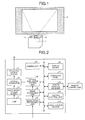
- FIG. 1 is an explanatory view of an example of a brief overview of an ultra short throw projector 1 according to the embodiment.
- a projection optical system 31 (an example of a projection unit) such as a projection lens is arranged on an upper surface of a chassis in the ultra short throw projector 1, and a light is radiated backward at an upper part from the projection optical system 31 to project an image onto a screen 2 as a projection surface.
- a focal point distance of the projection optical system 31 is configured to be less than a width of a body of a human person and shorter than a focal point distance of a projection optical system of a conventional projector
- a size of an image to be projected by the projection optical system 31 is configured to be equivalent to a size of an image to be projected by the conventional projector.
- the projection optical system 31 that realizes such an ultra short throw as explained is disclosed in Japanese Laid-open Patent Publication No. 2007-316674 , for example.
- a camera unit 44 (an example of an image capturing unit) is also arranged on the upper surface of the chassis.
- FIG. 2 is a block diagram of an example of a hardware configuration of the ultra short throw projector 1 according to the embodiment.
- the ultra short throw projector 1 is provided with the projection optical system 31, an optical modulator 32, an illumination optical system 33, a lamp 34, an optical modulator control unit 35, an image signal processing unit 37, an image processing unit 38, a system control unit 39, a display device 40, an operation panel 41, a remote control receiver 42, a remote controller 43, the camera unit 44, and an acceleration sensor 45 (an example of a detector).
- the image signal processing unit 37 processes an image signal input via a not-illustrated external interface.
- the image processing unit 38 performs processing of various kinds on a projection image which is an image signal processed by the image signal processing unit 37, a pattern image generated by the image processing unit 38, and a captured image captured by the camera unit 44.
- the pattern image is an image including a predetermined pattern. Details of the image processing unit 38 will be explained later.
- the optical modulator control unit 35 causes the optical modulator 32 to display the image on which processing of various kinds is performed by the image processing unit 38.
- the lamp 34 which will do as far as it radiates a light, functions as an optical source.
- the illumination optical system 33 which condenses a light radiated from the lamp 34 onto the optical modulator 32, can be realized by a lens and a mirror, for example.
- the optical modulator 32 which displays an image transmitted from the optical modulator control unit 35 and reflects or transmits the light condensed by the illumination optical system 33, can be realized by a digital mirror device (DMD), a liquid crystal panel, and the like.
- DMD digital mirror device
- the projection optical system 31, which projects an image on the screen 2 by projecting the light reflected or transmitted by the optical modulator 32 on the screen 2, can be realized by a lens and a mirror, for example.
- the system control unit 39 which controls components of the ultra short throw projector 1, can be realized by a processing device including a central processing unit (CPU), a random access memory (RAM), a read only memory (ROM), and the like.
- the system control unit 39 receives a notification from the operation panel 41 and the remote control receiver 42 to perform a process in accordance with the notification.
- the display device 40 which displays (announces) a state of the ultra short throw projector 1, can be realized by a light emitting diode (LED), for example.
- LED light emitting diode
- the display device 40 receives a notification from the system control unit 39 and displays the effect (turns on and off or lights the LED, for example).
- the operation panel 41 which notifies the system control unit 39 of various kinds of operational inputs by a user, can be realized by a touch screen, for example.
- the remote controller 43 notifies the remote control receiver 42 of various kinds of operational inputs by a user.
- the remote control receiver 42 notifies the system control unit 39 of the various kinds of inputs notified by the remote controller 43.
- the camera unit 44 which captures a pattern image which is projected on the screen 2 by the projection optical system 31, can be realized by a camera, for example.
- the acceleration sensor 45 which detects acceleration, detects a movement of the position of the ultra short throw projector 1 by detecting a force acting on the ultra short throw projector 1.
- FIG. 3 is a block diagram of an example of a configuration of the image processing unit 38 according to the embodiment. As illustrated in FIG. 3 , the image processing unit 38 includes a corrector 51 and a combiner 54.
- the corrector 51 which corrects a captured image captured by the camera unit 44 so that an imaging distortion caused due to image capturing and a projection distortion caused due to projection are corrected, includes an imaging distortion corrector 52 and a projection distortion corrector 53.
- the imaging distortion corrector 52 corrects an imaging distortion of the captured image captured by the camera unit 44.
- the projection distortion corrector 53 corrects a projection distortion of the captured image whose imaging distortion has been corrected by the imaging distortion corrector 52.
- the projection distortion corrector 53 may correct the projection distortion of the captured image captured by the camera unit 44 and the imaging distortion corrector 52 may correct the imaging distortion of the captured image whose projection distortion has been corrected by the projection distortion corrector 53.
- the combiner 54 generates a composite image by combining the pattern image generated by the image processing unit 38 and the captured image corrected by the corrector 51. For example, the combiner 54 generates the composite image so that the corrected captured image is combined at a center of a lower part of the pattern image.
- FIG. 4 is an explanatory view of an example of an installation situation of the ultra short throw projector 1 according to the embodiment.
- a light is radiated backward at an upper part from the projection optical system 31 to project an image on the screen 2 in the ultra short throw projector 1 according to the embodiment, a user 3 who arranges the ultra short throw projector 1 adjusts a position and an inclination of the ultra short throw projector 1 while looking up at the projected image from below.
- the image is seen by the user 3 as a distorted image of a trapezoidal shape in which an upper side becomes narrower (hereinafter this distortion being sometimes referred to as “distortion attributed to the direction of the line of sight”). It therefore becomes difficult for the user 3 to determine whether or not the distortion caused by the misalignment of the inclination angle between the ultra short throw projector 1 and the screen 2 (hereinafter this distortion being sometimes referred to as “distortion attributed to the misalignment of the inclination angle”) is resolved while adjusting the position and the inclination of the ultra short throw projector 1.
- the ultra short throw projector 1 projects, on the screen 2, an image whose distortion attributed to the direction of the line of sight of the user 3 is suppressed. Since the user 3 is thus able to see the image whose distortion attributed to the direction of the line of sight is suppressed, it becomes possible for the user 3 to determine whether or not the distortion attributed to the misalignment of the inclination angle is resolved while adjusting the position and the inclination of the ultra short throw projector 1.
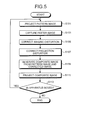
- FIG. 5 is a sequence diagram of an example of a processing to be executed in the ultra short throw projector 1 according to the embodiment.
- the projection optical system 31 projects a pattern image on the screen 2 (step S101).
- FIG. 6 illustrates an example of a pattern image 101 before projection according to the embodiment
- FIG. 7 illustrates an example of a pattern image 101' after projection according to the embodiment. While a plurality of feature points are arranged at regular intervals in a grid pattern in the pattern image 101 in the example illustrated in FIG. 6 , the present invention is not limited thereto.
- the distortion attributed to the misalignment of the inclination angle, i.e., the projection distortion associated with the projection is generated in the pattern image 101' projected on the screen 2.
- FIG. 8 illustrates an example of a captured image 110 according to the embodiment.
- the captured image 110 captured by the camera unit 44 includes the distortion attributed to the direction of the line of the sight, i.e., the imaging distortion associated with imaging. That is to say, the projection distortion and the imaging distortion arise in the captured image 110.
- the imaging distortion corrector 52 then corrects the imaging distortion of the captured image 110 captured by the camera unit 44 (step S105). Specifically, the imaging distortion corrector 52 performs a correction into an image for a case where the captured image 110 is assumed to be captured from an imaging direction perpendicular to the plane of the pattern image 101' projected on the screen 2.
- FIG. 9 illustrates an example of a captured image 110' after correcting an imaging distortion according to the embodiment. Since the captured image 110' illustrated in FIG. 9 is an image for the case of being assumed to be captured from the imaging direction perpendicular to the plane of the pattern image 101' and the imaging distortion is corrected, the distortion in the pattern image 101' is equivalent to that illustrated in FIG. 7 .
- Japanese Laid-open Patent Publication No. 2013-42411 discloses such a technique that an actual projector PRJr projects a pattern image, captures the pattern image by a camera equipped in the projector PRJr, and calculates virtual image data on the assumption that the pattern image is captured from a virtual projector PRJv which is assumed to be arranged on an extension of a normal line direction N of the screen by using the captured image and a perspective transformation matrix, as illustrated in FIG. 10 .
- the projection distortion corrector 53 then corrects the projection distortion of the captured image 110' whose imaging distortion has been corrected by the imaging distortion corrector 52 (step S107).
- the pattern image 101' in the captured image whose projection distortion is corrected is thus equivalent to that illustrated in FIG. 6 .
- Japanese Laid-open Patent Publication No. 2001-83949 discloses a technique of projecting a pattern image, capturing the projected pattern image, generating correction data for providing the captured image with a distortion opposite to the projection distortion, and correcting, by the correction data in advance, a projection distortion to be generated in the projection image.
- the combiner 54 then generates a composite image by combining the pattern image generated by the image processing unit 38 and a corrected image as the captured image corrected by the corrector 51 (step S109).
- FIG. 11 illustrates an example of a composite image 120 according to the embodiment.
- a corrected image 110" as the captured image whose projection distortion and imaging distortion are corrected is compounded at the center of the lower part of the pattern image 101.
- the projection distortion corrector 53 corrects a projection distortion of an entirety of the captured image 110' whose imaging distortion has been corrected.
- the combiner 54 compounds a part of the corrected image 110" at the center of the lower part of the pattern image 101, it is only necessary for the projection distortion corrector 53 to correct a projection distortion of the corresponding part.
- the projection optical system 31 then projects the composite image generated by the combiner 54 so that the corrected image 110" locates at a predetermined position of the screen 2 (step S111). While the predetermined position is configured to be the center of the lower part of the screen 2 in the embodiment since the user 3 adjusts the position and the inclination of the ultra short throw projector 1 while looking up at the projected image from below, the present invention is not limited thereto.
- the combiner 54 since the combiner 54 combines the corrected image 110" at the center of the lower part of the pattern image 101, the corrected image 110" locates at the center of the lower part of the screen 2 when the projection optical system 31 projects the composite image directly.
- FIG. 12 illustrates an example of a composite image 120' after projection according to the embodiment. Since locating at the center of the lower part of the screen 2 in the example illustrated in FIG. 12 , the corrected image 110" included in the composite image 120' is approximately perpendicular to the line of the sight of the user 3, which allows suppressing the distortion attributed to the direction of the line of the sight. Though a projection distortion arises in the pattern image within the corrected image 110" in the example illustrated in FIG. 12 , the ultra short throw projector 1 is adjusted to the position and the inclination at which no misalignment of the inclination angle between the ultra short throw projector 1 and the screen 2 arises as far as there is no projection distortion in the pattern image within the corrected image 110".
- the acceleration sensor 45 detects whether or not the position of the ultra short throw projector 1 is moved (step S113). Specifically, the system control unit 39 regularly obtains measurement values of the acceleration from the acceleration sensor 45, checks a change in the obtained measurement values, and then detects whether or not the position of the ultra short throw projector 1 is moved. When a force for moving the position of the ultra short throw projector 1 is applied to the ultra short throw projector 1, a measurement value of the acceleration becomes large and when a force is not applied to the ultra short throw projector 1, a measurement value of the acceleration becomes small.
- step S113 When the acceleration sensor 45 detects the movement of the position of the ultra short throw projector 1 ("Yes" at step S113), the processing returns to step S101, the projection optical system 31 projects the pattern image again (step S101), and the camera unit 44 captures the pattern image 101' again projected on the screen 2 (step S103). This is because the inclination angle with the screen 2 changes and the distortion attributed to the misalignment of the inclination angle also changes when the position of the ultra short throw projector 1 is moved.
- the composite image 120' is projected on the screen 2 in a manner of suppressing the distortion attributed to the direction of the line of the sight of the user 3 in the embodiment.
- the composite image 120' is equivalent to the pattern image 101' seen from a position where the plane of the pattern image 101' projected on the screen 2 becomes perpendicular to the direction of the line of the sight of the user 3. Therefore, it is possible for the user 3 to determine whether or not the distortion attributed to the misalignment of the inclination angle is resolved by checking the projection distortion of the pattern image within the corrected image 110" included in the composite image 120' while adjusting the position and the inclination of the ultra short throw projector 1.
- the user 3 it is thus possible for the user 3 to make a positional adjustment, for resolving a distortion in a projection image, of the ultra short throw projector 1 without extra cost and efforts.
- the composite image 120' is generated from the pattern image 101 and the corrected image 110" in the embodiment, an installation personnel checks the corrected image 110" and the others check the pattern image 101 in making a positional adjustment of the ultra short throw projector 1 by multiple persons, so that it is possible to accurately determine whether or not the distortion attributed to the misalignment of the inclination angle is resolved.
- a program to be executed in the ultra short throw projector 1 according to the embodiment is provided by being stored in a file of an installable format or of an executable format in a computer-readable storage medium such as a CD-ROM, a CD-R, a memory card, a digital versatile disk (DVD), and a flexible disk (FD).
- a computer-readable storage medium such as a CD-ROM, a CD-R, a memory card, a digital versatile disk (DVD), and a flexible disk (FD).
- the program to be executed in the ultra short throw projector 1 according to the embodiment may be provided by being stored on a computer connected to a network such as the Internet and downloaded via the network. Besides, the program to be executed in the ultra short throw projector 1 according to the embodiment may be provided or distributed via a network such as the Internet. Moreover, the program to be executed in the ultra short throw projector 1 according to the embodiment may be provided by being preloaded in a ROM and the like.
- the program to be executed in the ultra short throw projector 1 has a module configuration that enables the above-described components to be realized on a computer.
- a CPU reads out from a ROM onto a RAM and executes the program, so that each component is realized on the computer.
- the corrected image 110" is combined at the center of the lower part of the pattern image 101 and projected in the embodiment, the corrected image 110" may be projected to locate at a center of a lower part of the screen 2. It is possible in this configuration, too to obtain the same advantage as the embodiment.
- acceleration sensor 45 is taken as an example in the embodiment, the present invention is not limited thereto and a gyroscopic sensor, a ranging sensor that measures a distance to the screen, and the like may be used.
Landscapes
- Engineering & Computer Science (AREA)
- Multimedia (AREA)
- Signal Processing (AREA)
- Physics & Mathematics (AREA)
- Geometry (AREA)
- General Physics & Mathematics (AREA)
- Transforming Electric Information Into Light Information (AREA)
- Projection Apparatus (AREA)
Applications Claiming Priority (1)
| Application Number | Priority Date | Filing Date | Title |
|---|---|---|---|
| JP2013242246A JP2015103922A (ja) | 2013-11-22 | 2013-11-22 | 画像投影装置、画像投影方法及びプログラム |
Publications (2)
| Publication Number | Publication Date |
|---|---|
| EP2876876A2 true EP2876876A2 (de) | 2015-05-27 |
| EP2876876A3 EP2876876A3 (de) | 2015-07-22 |
Family
ID=51904844
Family Applications (1)
| Application Number | Title | Priority Date | Filing Date |
|---|---|---|---|
| EP14194117.9A Withdrawn EP2876876A3 (de) | 2013-11-22 | 2014-11-20 | Bildprojektionsvorrichtung, Bildprojektionsverfahren und computerlesbares Speichermedium |
Country Status (4)
| Country | Link |
|---|---|
| US (1) | US9621820B2 (de) |
| EP (1) | EP2876876A3 (de) |
| JP (1) | JP2015103922A (de) |
| CN (1) | CN104660944A (de) |
Cited By (1)
| Publication number | Priority date | Publication date | Assignee | Title |
|---|---|---|---|---|
| EP3270588A3 (de) * | 2016-07-15 | 2018-03-28 | Panasonic Intellectual Property Management Co., Ltd. | Bildverarbeitungsvorrichtung zur bildprojektion, bildprojektionsvorrichtung und bildverarbeitungsverfahren |
Families Citing this family (8)
| Publication number | Priority date | Publication date | Assignee | Title |
|---|---|---|---|---|
| JPWO2017179111A1 (ja) * | 2016-04-12 | 2019-01-17 | マクセル株式会社 | 表示システムおよび情報処理方法 |
| US10885711B2 (en) | 2017-05-03 | 2021-01-05 | Microsoft Technology Licensing, Llc | Virtual reality image compositing |
| CN109257582B (zh) * | 2018-09-26 | 2020-12-04 | 海信视像科技股份有限公司 | 一种投影设备的校正方法和装置 |
| CN110281665B (zh) * | 2019-07-11 | 2021-03-30 | 深圳市汉森软件有限公司 | 通过参考线定位打印介质的打印方法、装置、设备及介质 |
| CN110281666B (zh) * | 2019-07-11 | 2021-03-30 | 深圳市汉森软件有限公司 | 通过图像投影定位打印介质的方法、装置、设备及介质 |
| KR102803131B1 (ko) | 2020-04-02 | 2025-05-07 | 삼성전자주식회사 | 영상 투사 장치 및 영상 투사 장치의 제어 방법 |
| CN114189722B (zh) * | 2021-12-20 | 2023-07-25 | 四川长虹电器股份有限公司 | 一种屏幕显示方法 |
| CN117288095B (zh) * | 2023-11-27 | 2024-02-13 | 浙江极氪汽车研究开发有限公司 | 一种门槛照地灯的检测装置及方法 |
Citations (4)
| Publication number | Priority date | Publication date | Assignee | Title |
|---|---|---|---|---|
| JP2001083949A (ja) | 1999-09-16 | 2001-03-30 | Japan Science & Technology Corp | 映像投影装置 |
| JP2007316674A (ja) | 2003-02-06 | 2007-12-06 | Ricoh Co Ltd | 投射光学系、拡大投射光学系、拡大投射装置及び画像投射装置 |
| JP2012199772A (ja) | 2011-03-22 | 2012-10-18 | Seiko Epson Corp | プロジェクター及びプロジェクターの設置方法 |
| JP2013042411A (ja) | 2011-08-18 | 2013-02-28 | Ricoh Co Ltd | 画像処理装置、その画像処理装置を有するプロジェクタ及びプロジェクタシステム、並びに、画像処理方法、そのプログラム、及び、そのプログラムを記録した記録媒体 |
Family Cites Families (8)
| Publication number | Priority date | Publication date | Assignee | Title |
|---|---|---|---|---|
| US6753907B1 (en) | 1999-12-23 | 2004-06-22 | Justsystem Corporation | Method and apparatus for automatic keystone correction |
| JP5124965B2 (ja) | 2006-03-29 | 2013-01-23 | カシオ計算機株式会社 | 投影装置、投影方法及びプログラム |
| JP5205865B2 (ja) | 2007-08-22 | 2013-06-05 | セイコーエプソン株式会社 | 投射画像の形状歪補正支援システム、投射画像の形状歪補正支援方法、及びプロジェクタ、並びにプログラム |
| JP5251202B2 (ja) * | 2008-03-27 | 2013-07-31 | セイコーエプソン株式会社 | プロジェクタの投射画像の歪補正方法、及びプロジェクタ |
| JP5493340B2 (ja) | 2008-11-26 | 2014-05-14 | セイコーエプソン株式会社 | 投写型表示装置および配置関係検出方法 |
| JP5744418B2 (ja) * | 2010-05-18 | 2015-07-08 | キヤノン株式会社 | 投影装置及び投影方法 |
| JP5796286B2 (ja) * | 2010-09-15 | 2015-10-21 | セイコーエプソン株式会社 | プロジェクター、及び、プロジェクターの制御方法 |
| US9128366B2 (en) * | 2012-05-22 | 2015-09-08 | Ricoh Company, Ltd. | Image processing system, image processing method, and computer program product |
-
2013
- 2013-11-22 JP JP2013242246A patent/JP2015103922A/ja active Pending
-
2014
- 2014-11-10 US US14/536,717 patent/US9621820B2/en not_active Expired - Fee Related
- 2014-11-19 CN CN201410664320.7A patent/CN104660944A/zh active Pending
- 2014-11-20 EP EP14194117.9A patent/EP2876876A3/de not_active Withdrawn
Patent Citations (4)
| Publication number | Priority date | Publication date | Assignee | Title |
|---|---|---|---|---|
| JP2001083949A (ja) | 1999-09-16 | 2001-03-30 | Japan Science & Technology Corp | 映像投影装置 |
| JP2007316674A (ja) | 2003-02-06 | 2007-12-06 | Ricoh Co Ltd | 投射光学系、拡大投射光学系、拡大投射装置及び画像投射装置 |
| JP2012199772A (ja) | 2011-03-22 | 2012-10-18 | Seiko Epson Corp | プロジェクター及びプロジェクターの設置方法 |
| JP2013042411A (ja) | 2011-08-18 | 2013-02-28 | Ricoh Co Ltd | 画像処理装置、その画像処理装置を有するプロジェクタ及びプロジェクタシステム、並びに、画像処理方法、そのプログラム、及び、そのプログラムを記録した記録媒体 |
Cited By (3)
| Publication number | Priority date | Publication date | Assignee | Title |
|---|---|---|---|---|
| EP3270588A3 (de) * | 2016-07-15 | 2018-03-28 | Panasonic Intellectual Property Management Co., Ltd. | Bildverarbeitungsvorrichtung zur bildprojektion, bildprojektionsvorrichtung und bildverarbeitungsverfahren |
| US10101957B2 (en) | 2016-07-15 | 2018-10-16 | Panasonic Intellectual Property Management Co., Ltd. | Image processing device for image projection, image projection apparatus, and image processing method |
| US10303414B2 (en) | 2016-07-15 | 2019-05-28 | Panasonic Intellectual Property Management Co., Ltd. | Device, system, and method of controlling projection image |
Also Published As
| Publication number | Publication date |
|---|---|
| JP2015103922A (ja) | 2015-06-04 |
| US20150146047A1 (en) | 2015-05-28 |
| EP2876876A3 (de) | 2015-07-22 |
| US9621820B2 (en) | 2017-04-11 |
| CN104660944A (zh) | 2015-05-27 |
Similar Documents
| Publication | Publication Date | Title |
|---|---|---|
| US9621820B2 (en) | Image projection apparatus, image projection method, and computer-readable storage medium | |
| CN103650024B (zh) | 投影显示设备、信息处理设备、投影显示系统和程序 | |
| EP3139600B1 (de) | Projektionsverfahren | |
| US20150103147A1 (en) | Image calibration system and calibration method of a stereo camera | |
| US8403500B2 (en) | Projector and method of controlling projector | |
| KR101820905B1 (ko) | 촬영장치에 의해 촬영된 이미지 기반의 투사영역 자동보정 방법 및 이를 위한 시스템 | |
| US20140267427A1 (en) | Projector, method of controlling projector, and program thereof | |
| EP2677754A2 (de) | Projektor, Trapezverzerrungskorrekturverfahren, ein Trapezverzerrungskorrekturprogramm speicherndes Trägermedium und Trapezverzerrungskorrekturprogramm | |
| US20110254810A1 (en) | User interface device and method for recognizing user interaction using same | |
| KR20160119444A (ko) | 교정 방법, 교정 장치 및 컴퓨터 프로그램 제품 | |
| US9568811B2 (en) | Projector and projection image control method | |
| JP2014197739A5 (de) | ||
| JPWO2017179453A1 (ja) | 検査装置、検査方法 | |
| US20160119602A1 (en) | Control apparatus, control method, and storage medium | |
| US10983424B2 (en) | Image projection apparatus and storage medium capable of adjusting curvature amount of image plane | |
| US20160142691A1 (en) | Image processing apparatus, image projection system, image processing method, and computer program product | |
| CN108781268B (zh) | 图像处理装置和方法 | |
| JP2019176356A (ja) | プロジェクター、及び、プロジェクターの制御方法 | |
| JP2016085380A (ja) | 制御装置、制御方法、及び、プログラム | |
| US10868962B2 (en) | Image capturing apparatus performing image stabilization, control method thereof, and storage medium | |
| CN108141561A (zh) | 投影型显示装置和图像校正方法 | |
| US20150138512A1 (en) | Information processing apparatus, image projecting apparatus, and method for providing distortion correction instruction | |
| KR20160150283A (ko) | 광학 시스템 및 광학 기구의 이미지 보정 방법 | |
| JP2005148381A (ja) | プロジェクタおよび移動検出方法、映像調整方法 | |
| US11979661B1 (en) | Method for performing light shaping with aid of adaptive projector, and associated apparatus |
Legal Events
| Date | Code | Title | Description |
|---|---|---|---|
| PUAI | Public reference made under article 153(3) epc to a published international application that has entered the european phase |
Free format text: ORIGINAL CODE: 0009012 |
|
| 17P | Request for examination filed |
Effective date: 20141120 |
|
| AK | Designated contracting states |
Kind code of ref document: A2 Designated state(s): AL AT BE BG CH CY CZ DE DK EE ES FI FR GB GR HR HU IE IS IT LI LT LU LV MC MK MT NL NO PL PT RO RS SE SI SK SM TR |
|
| AX | Request for extension of the european patent |
Extension state: BA ME |
|
| PUAL | Search report despatched |
Free format text: ORIGINAL CODE: 0009013 |
|
| AK | Designated contracting states |
Kind code of ref document: A3 Designated state(s): AL AT BE BG CH CY CZ DE DK EE ES FI FR GB GR HR HU IE IS IT LI LT LU LV MC MK MT NL NO PL PT RO RS SE SI SK SM TR |
|
| AX | Request for extension of the european patent |
Extension state: BA ME |
|
| RIC1 | Information provided on ipc code assigned before grant |
Ipc: G03B 21/14 20060101ALI20150617BHEP Ipc: H04N 9/31 20060101AFI20150617BHEP Ipc: G03B 21/26 20060101ALI20150617BHEP |
|
| STAA | Information on the status of an ep patent application or granted ep patent |
Free format text: STATUS: THE APPLICATION HAS BEEN WITHDRAWN |
|
| 18W | Application withdrawn |
Effective date: 20151209 |