EP2876896B1 - Transducteur audio avec protection contre les décharges électrostatiques - Google Patents
Transducteur audio avec protection contre les décharges électrostatiques Download PDFInfo
- Publication number
- EP2876896B1 EP2876896B1 EP14191973.8A EP14191973A EP2876896B1 EP 2876896 B1 EP2876896 B1 EP 2876896B1 EP 14191973 A EP14191973 A EP 14191973A EP 2876896 B1 EP2876896 B1 EP 2876896B1
- Authority
- EP
- European Patent Office
- Prior art keywords
- wiring board
- printed wiring
- membrane
- electrical
- ground
- Prior art date
- Legal status (The legal status is an assumption and is not a legal conclusion. Google has not performed a legal analysis and makes no representation as to the accuracy of the status listed.)
- Active
Links
Images



Classifications
-
- H—ELECTRICITY
- H04—ELECTRIC COMMUNICATION TECHNIQUE
- H04R—LOUDSPEAKERS, MICROPHONES, GRAMOPHONE PICK-UPS OR LIKE ACOUSTIC ELECTROMECHANICAL TRANSDUCERS; ELECTRIC HEARING AIDS; PUBLIC ADDRESS SYSTEMS
- H04R9/00—Transducers of moving-coil, moving-strip, or moving-wire type
- H04R9/02—Details
- H04R9/04—Construction, mounting, or centering of coil
-
- H—ELECTRICITY
- H04—ELECTRIC COMMUNICATION TECHNIQUE
- H04R—LOUDSPEAKERS, MICROPHONES, GRAMOPHONE PICK-UPS OR LIKE ACOUSTIC ELECTROMECHANICAL TRANSDUCERS; ELECTRIC HEARING AIDS; PUBLIC ADDRESS SYSTEMS
- H04R9/00—Transducers of moving-coil, moving-strip, or moving-wire type
- H04R9/02—Details
-
- H—ELECTRICITY
- H04—ELECTRIC COMMUNICATION TECHNIQUE
- H04R—LOUDSPEAKERS, MICROPHONES, GRAMOPHONE PICK-UPS OR LIKE ACOUSTIC ELECTROMECHANICAL TRANSDUCERS; ELECTRIC HEARING AIDS; PUBLIC ADDRESS SYSTEMS
- H04R19/00—Electrostatic transducers
- H04R19/01—Electrostatic transducers characterised by the use of electrets
- H04R19/016—Electrostatic transducers characterised by the use of electrets for microphones
-
- H—ELECTRICITY
- H04—ELECTRIC COMMUNICATION TECHNIQUE
- H04R—LOUDSPEAKERS, MICROPHONES, GRAMOPHONE PICK-UPS OR LIKE ACOUSTIC ELECTROMECHANICAL TRANSDUCERS; ELECTRIC HEARING AIDS; PUBLIC ADDRESS SYSTEMS
- H04R31/00—Apparatus or processes specially adapted for the manufacture of transducers or diaphragms therefor
- H04R31/003—Apparatus or processes specially adapted for the manufacture of transducers or diaphragms therefor for diaphragms or their outer suspension
-
- H—ELECTRICITY
- H04—ELECTRIC COMMUNICATION TECHNIQUE
- H04R—LOUDSPEAKERS, MICROPHONES, GRAMOPHONE PICK-UPS OR LIKE ACOUSTIC ELECTROMECHANICAL TRANSDUCERS; ELECTRIC HEARING AIDS; PUBLIC ADDRESS SYSTEMS
- H04R2225/00—Details of deaf aids covered by H04R25/00, not provided for in any of its subgroups
- H04R2225/49—Reducing the effects of electromagnetic noise on the functioning of hearing aids, by, e.g. shielding, signal processing adaptation, selective (de)activation of electronic parts in hearing aid
-
- H—ELECTRICITY
- H04—ELECTRIC COMMUNICATION TECHNIQUE
- H04R—LOUDSPEAKERS, MICROPHONES, GRAMOPHONE PICK-UPS OR LIKE ACOUSTIC ELECTROMECHANICAL TRANSDUCERS; ELECTRIC HEARING AIDS; PUBLIC ADDRESS SYSTEMS
- H04R2307/00—Details of diaphragms or cones for electromechanical transducers, their suspension or their manufacture covered by H04R7/00 or H04R31/003, not provided for in any of its subgroups
- H04R2307/027—Diaphragms comprising metallic materials
-
- Y—GENERAL TAGGING OF NEW TECHNOLOGICAL DEVELOPMENTS; GENERAL TAGGING OF CROSS-SECTIONAL TECHNOLOGIES SPANNING OVER SEVERAL SECTIONS OF THE IPC; TECHNICAL SUBJECTS COVERED BY FORMER USPC CROSS-REFERENCE ART COLLECTIONS [XRACs] AND DIGESTS
- Y10—TECHNICAL SUBJECTS COVERED BY FORMER USPC
- Y10T—TECHNICAL SUBJECTS COVERED BY FORMER US CLASSIFICATION
- Y10T29/00—Metal working
- Y10T29/49—Method of mechanical manufacture
- Y10T29/49002—Electrical device making
- Y10T29/49005—Acoustic transducer
Definitions
- the invention relates generally to a sound transducer and, more particularly, to electrostatic protection.
- Speakers which have a metal membrane as a diaphragm.
- US 2,857,461 teaches a speaker diaphragm controlled capacitor for negative feedback control.
- the speaker has a conventional construction and includes a metallic frame with a conical diaphragm carrying a voice coil connected through the amplifier output and movable in a constant magnetic field.
- a thin plate of conductive material such as a metallic foil may be disposed on the diaphragm and may be connected through a flexible lead to the frame of the speaker which may be at a ground potential.
- the thin plate on the diaphragm forms a parallel plate capacitor with a fixed plate carried in the frame of the speaker.
- US 3,061,675 relates to a loudspeaker system.
- the loudspeaker system comprises a conductive diaphragm which is positioned between two apertured conductive plates.
- the diaphragm is connected to a reference potential which may be ground.
- US 5,878,149 relates to a loudspeaker.
- the loudspeaker comprises a diaphragm made of metal mounted on a plate and supported by an annular frame at an edge.
- the edge of the diaphragm is coated with a coating layer such as electrical conductive foil or paste.
- the diaphragm is connected to the ground through the coating layer so that the electric potential of the diaphragm is equal to a minus terminal of the voice coil.
- an apparatus and method in accordance with the independent claims including a diaphragm comprising a membrane, where the membrane comprises electrically conductive material; a drive configured to move the diaphragm; and a connector configured to connect the membrane to a ground.
- an example method comprises providing a speaker diaphragm, where the speaker diaphragm comprises a membrane, where the membrane comprises electrically conductive material, where the membrane comprises a connector configured to connect the membrane to a ground; and connecting the diaphragm to a drive, where the drive is configured to move the diaphragm.
- an example method comprises providing a speaker comprising a diaphragm which includes a membrane, where the membrane comprises electrically conductive material, where the membrane comprises an electrical connection section; and connecting the speaker to a printed wiring board, where, when the speaker is connected to the printed wiring board, the membrane is electrically connected through the electrical connection section to the printed wiring board.
- FIG. 1 there is shown a front view of an apparatus 10 incorporating features of an example embodiment.
- a front view of an apparatus 10 incorporating features of an example embodiment.
- the features will be described with reference to the example embodiments shown in the drawings, it should be understood that features can be embodied in many alternate forms of embodiments.
- any suitable size, shape or type of elements or materials could be used.
- the apparatus 10 may be a hand-held portable apparatus, such as a communications device which includes a telephone application for example.
- the apparatus 10 is a smartphone which includes a camera and a camera application.
- the apparatus 10 may additionally or alternatively comprise an Internet browser application, a video recorder application, a music player and recorder application, an email application, a navigation application, a gaming application, and/or any other suitable electronic device application.
- the apparatus might not be a smartphone.
- the apparatus might be a video recorder or a hand-held gaming device for example.
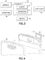
- the apparatus 10 in this example embodiment, comprises a housing 12, a touchscreen 14, a receiver 16, a transmitter 18, a controller 20, a rechargeable battery 26 and a camera 30.
- a housing 12 for storing data
- a touchscreen 14 for storing data
- a transmitter 18 for converting DC to DC to AC to DC.
- the receiver and the transmitter may be provided in the form of a transceiver for example.
- the controller 20 may include at least one processor 22, at least one memory 24, and software.
- the electronic circuitry inside the housing 12 may comprise at least one printed wiring board (PWB) having components such as the controller 20 thereon.
- PWB printed wiring board
- the receiver 16 and transmitter 18 form a primary communications system to allow the apparatus 10 to communicate with a wireless telephone system, such as a mobile telephone base station for example.
- the apparatus 10 includes the camera 30 which is located at the rear side 13 of the apparatus, a front camera 32, an LED 34, and a flash system 36.
- the LED 34 and the flash system 36 are also visible at the rear side of the apparatus, and are provided for the camera 30.
- the cameras 30, 32, the LED 34 and the flash system 36 are connected to the controller 20 such that the controller 20 may control their operation.
- the rear side may comprise more than one camera, and/or the front side could comprise more than one camera.
- the apparatus 10 includes a sound transducer provided as an air microphone 38. In an alternate example the apparatus may comprise more than one air microphone.
- the apparatus 10 also includes a speaker or earpiece 28 which comprises a sound transducer.
- the apparatus 10 includes a speaker 40.
- the housing 12 comprises at least one sound hole 33 for sound to travel from the earpiece 28, at least one sound hole 39 for sound to travel to the microphone, and sound holes 42 for sound to travel from the speaker 40.
- the description which follows will be in regard to the area at the speaker 40. However, the features described are equally applicable to other coil/magnet assemblies. Features of the invention could be used at the earpiece 28 for example.
- the diaphragm 48 of the speaker 40 has its outer perimeter connected to a housing 50 which can be mounted to a backside of a frame piece 52.
- the speaker 40 includes a magnet system 44, a coil 46, and the diaphragm 48 connected to the coil 44.
- the magnet system 44 comprises at least one permanent magnet 54 and pole pieces 56a, 56b.
- the magnet could be an electromagnet. More than two pole pieces could be provided.
- Some examples of magnet and pole piece arrangements are described and shown in U.S. patent publication No. 2013/0278364 A1 .
- the coil 46 is energized to move the coil 46 and the diaphragm 48 relative to the magnet system 44 as indicated by arrow 58.
- the diaphragm 48 comprises an membrane 60.
- the membrane 60 comprises an electrically conductive material.
- the metal membrane 60 may comprises aluminum for example. As the membrane 60 is moved as indicated by arrow 58, sound is produced from the speaker 40.
- the membrane 60 includes at least one electrical connector 62.
- the electrical connector or contact 62 may be a ground pin for example.
- the electrical connector 62 in this example comprises two electrical connectors 62a, 62b. In an alternate example embodiment more or less than two connectors may be provided. For example, in one example embodiment only the electrical connector 62a may be provided. As another example embodiment, only the electrical connector 62b may be provided. In one type of example embodiment the contacts 62 are integrally formed with the metal membrane 60. However, in an alternate example the connector/contact 62 for the metal membrane 60 may not be integrally formed with the metal membrane.
- the electrical connector(s) could be a separate member from the metal membrane.
- Each of the electrical connectors 62a, 62b comprise an electrical connection area 64 to connect the metal membrane 60 to ground.
- an indication that a connector(s) is configured to connect the membrane to ground is intended to include where a galvanic connection is provided of the connector to the ground or where a small gap is provided between the connector and the ground (as further described below).
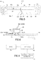
- the first electrical connector 62a is a resiliently deflectable cantilevered arm having its electrical connection area 64 at the distal end of the arm.
- the electrical connection area 64 of the first electrical connector 62a is located against the top surface of the pole piece 56a.
- the pole piece 56b is mounted on the printed wiring board (PWB) 66 and is electrically connected to a ground layer 68 of the PWB 66.
- PWB printed wiring board
- the second electrical connector 62b is a resiliently deflectable cantilevered arm having its electrical connection area 64 at the distal end of the arm.
- the electrical connection area 64 of the second electrical connector 62b is located against the top surface of the PWB 66; against a contact pad 70 of the ground layer 68.
- the metal membrane 60 is electrically connected to the ground layer 68 by the connector 62b.
- One or both of the connectors 62 may comprise, for example, a spring terminal, a leaf terminal, or a non-resilient terminal, such as connection pads suitably designed as part of the transducer chassis.
- Speakers may be used with speakers, earpieces, transducer integration to mechanics, acoustics, and ESD protection.
- Features may apply to any type of speaker or earpiece in mobile devices, such as mobile phones, tablets, navigation devices, PDAs and laptops.
- a spark from an electrostatic discharge (ESD) can easily upset or break a modern integrated handsfree (IHF) speaker amplifier 72 when the ESD conducts into the sound outlet and to the speaker.
- IHF integrated handsfree
- Modern speaker amplifiers are very vulnerable to ESD due to limitations in silicon area, cost, and increased digital signal processing (DSP) on chip (audio DSP algorithms, speaker protection, etc).
- One type of fix for the problem may comprise adding passive components (ferrites, varistors) in speaker lines to protect the amplifier 72.
- passive components are costly, they require PWB footprint, cause extra logistics effort, slow down production and add complexity.
- the audio performance will be lower than with a simple circuit with less losses and resistance.
- Another way to protect the speaker from an ESD spark is to add a metal plate in front of the speaker that presents low impedance to ground for the ESD spark, so that the ESD spark can be guided to ground. This can be achieved by either directly grounding the metal plate to the system ground or very narrow spark gap to the ground.
- adding a separate metal plate is rarely possible in product design due to added Z height and design complexity.
- the extra plate needs to be acoustically sealed to the component by adhesive or a poron layer which add more Z height, and adds design and assembly complexity.
- Such kind of structure is also challenging for design and assembly task and, in many products, not even possible.
- Adding a separate metal plate and acoustically sealing it with adhesive/poron layer might be provided without grounding the plate, but the plate would be floating (not grounded), and it is not possible to get low impedance to ground so that an ESD spark can be easily guided to ground.
- a floating plate in that way has a high ESD risk. Grounding the plate requires extra design effort from product mechanics and is not possible in many designs.
- Some conventional mobile phones use a speaker with a metal (e.g., aluminum) membrane to get better bass effect. However, the metal membrane is not connected to ground and, therefore, does not provide ESD shielding as noted in the floating plate construction described above.
- Electrodes as described herein may be used to solve the ESD shielding problem with use of a metal speaker membrane as an ESD shield by connecting the metal membrane to ground.
- the ESD shield does not need to be provide as a separate part.
- a single member such as membrane 60
- the result is a re-designed speaker with an integrated ESD protection.
- Grounding the front metal plate to the PWB may be provided by designing a third contact leg from the speaker to the PWB (where the coil has the two other contact legs/leads 74, 75 shown in Figs. 7-8 ). By merely connecting the metal plate 60 to ground, this will take care of the ESD problem.
- Features as described herein may provide a ready solution (fully integrated speaker component) that includes the grounded metal plate for ESD protection.
- metal membrane as both a speaker diaphragm and as an ESD shield reduces the total solution Z thickness because no separate adhesive/poron layer is needed between the speaker component and shield plate.
- logistics and mechanical integration it is more convenient to have the whole package integrated as one unit compared to building the solution from pieces and designing separate wiring for grounding the metal plate onto the PWB.
- ESD is firstly attracted by the metal membrane and then guided to system ground 68 in the PWB through the low impedance path between the membrane 60 and system ground.
- the low impedance path can be achieved by either the direct Galvanic connection or a small air gap (e.g., ⁇ 0.5mm) between the membrane and the GND.
- the connector(s) may be configured to indirectly connect the membrane to ground through a small air gap; not necessarily a direct connection to the ground.
- the driver 72 can be damaged by a 12kV air discharge.
- spark routing protocol (SPR) at 15kV can be passed.
- SPR spark routing protocol
- ESD protection may be provided. It can effectively trap the ESD sparks from all the directions to the speaker and guide them to ground, providing effective protection for both positive and negative terminals of the driver 72. There is no penalty in z-direction thickness as there is no need for an additional metal layer below or above the module. There is minimal cost increase as there is no need for an additional metal film. Regarding the impact on acoustic performance, this can be minimal.
- the grounding contact(s) 62 on the membrane 60 may be located at where the membrane 60 is fixed to the housing 50, therefore, it will not impact the vibration of the diaphragm. ESD protection also works without direct galvanic contact, if the air gap between the membrane and the grounding is small enough (such as less than 0.5mm for example).
- the metal membrane 60 may be connected/wired to a separate ground pin internally (now shown). However, a dedicated ground pin(s) is not required because the membrane can connect to the pole piece/magnet (below which is electrically conductive), and/or can be connected to ground by an external spring/leaf/conducting gasket on the PWB (or flexible printed circuit FPC).
- FIG. 7 and 8 bottom views an example embodiment of the speaker 40 is shown.
- 74, 75 are electrical leads for the coil 46.
- Two of the electrical connectors 62b are provided.
- the connectors 62b each have a general cantilevered shape which is surface mounted to the PWB 66.
- the connectors 62b are electrically connected to the diaphragm at the perimeter edge of the diaphragm; where the diaphragm is connected to the housing 50. Therefore, the connectors 62b will not impact the vibration of the diaphragm.
- the diaphragm may comprise an assembly of components such as a resilient polymer membrane with a sprayed-on or attached electrically conductive member with a connector or contact to connect the metal member to ground. For the example embodiment shown in Figs.
- the speaker 40 has both the electrical leads 74, 75 to drive the coil 46, and at least one additional terminal (in this example terminals 62b) which all connect to a printed wiring board 66 when the speaker 40 is mounted to the PWB 66.
- the speaker 40 has at least one additional contact terminal for the speaker module in addition to the electrical terminals 74, 75 for driving the speaker.
- an example embodiment may comprise the diaphragm 48, a drive 78 and the electrical connector/contact 62.
- the drive 78 may comprise the coil 46 and permanent magnet(s) 44 described above.
- the drive may comprise, for example, a piezoelectric drive or an electrostatic drive, such as for a piezoelectric speaker or a electrostatic speaker. Any suitable drive could be used.
- An example embodiment may be provided in an apparatus comprising a magnet system; at least one pole piece connected to the magnet system; a coil; and a diaphragm connected to the coil, where the diaphragm comprises a metal membrane having a connector for electrically connecting the metal membrane to ground.
- the apparatus may further comprise electrical insulation 76 between the metal membrane and the coil.
- the connector may comprise a resilient electrical contact arm which is configured to resiliently deflect.
- the resilient electrical contact arm may comprise a surface mount contact area adapted to make a surface contact with another member.
- the resilient electrical contact arm may make the surface contact with a contact pad on a printed wiring board.
- the resilient electrical contact arm may make the surface contact with a first one of the at least one pole piece.
- the connector may be electrically connected in series to a first one of the at least one pole piece, at least one magnet of the magnet system, and a second one of the at least one pole piece.
- the apparatus may comprise means for electrostatic discharge shielding comprising the metal membrane of the diaphragm.
- the apparatus may further comprise a printed wiring board having a ground, where the metal membrane is connected to the ground by the connector; an electrical display connected to the printed wiring board; a receiver connected to the printed wiring board; a transmitter connected to the printed wiring board; a processor connected to the printed wiring board; a memory connected to the printed wiring board; and a battery connected to the printed wiring board.
- An example method may comprise providing a speaker diaphragm comprising a metal membrane, where the metal membrane comprises an electrical connection area adapted to connect the metal membrane to ground; and connecting the diaphragm to a coil.
- the method may further comprise electrically insulating the metal membrane from the coil.
- the metal membrane may comprise a resiliently deflectable arm having the electrical connection area thereon. A majority of the metal membrane may be stationarily connected to the coil to move with the coil.
- the method may further comprise electrically connecting the electrical connection area of the metal membrane on an electrical contact pad of a printed wiring board.
- the method may further comprise electrically connecting the electrical connection area of the metal membrane on to a pole piece connected to a magnet.
- An example method may comprise providing a speaker comprising a diaphragm which includes a metal membrane, where the metal membrane comprises an electrical connection section; and connecting the speaker to a printed wiring board, where, when the speaker is connected to the printed wiring board, the metal membrane is electrically connected through the electrical connection section to the printed wiring board.
- the electrical connection section of the metal membrane may be provided as a resiliently deflectable arm having the electrical connection area thereon.
- the electrical connection area may contact a contact pad on the printed wiring board.
- the electrical connection area may contact a pole piece of the speaker, where the metal membrane is electrically connected to the printed wiring board through the pole piece.
- Connecting the speaker to the printed wiring board may comprise resiliently deflecting the electrical connection section of the metal membrane.
Landscapes
- Engineering & Computer Science (AREA)
- Physics & Mathematics (AREA)
- Acoustics & Sound (AREA)
- Signal Processing (AREA)
- Manufacturing & Machinery (AREA)
- Audible-Bandwidth Dynamoelectric Transducers Other Than Pickups (AREA)
- Details Of Audible-Bandwidth Transducers (AREA)
Claims (13)
- Appareil (10), comprenant :une carte de circuit imprimé (66) ayant une masse (68);un dispositif d'affichage électrique connecté à la carte de circuit imprimé ;un récepteur connecté à la carte de circuit imprimé ;un émetteur connecté à la carte de circuit imprimé ;un processeur connecté à la carte de circuit imprimé ;une mémoire connectée à la carte de circuit imprimé ; etune batterie connectée à la carte de circuit imprimé ; etun module de haut-parleur (40) monté sur la carte de circuit imprimé comprenant : un diaphragme (48) constitué d'une membrane (60) comprenant un matériau électriquement conducteur ;un entraînement (78, 44, 46) configuré pour déplacer le diaphragme (48) lorsqu'un signal audio est reçu, où le diaphragme (48) et l'entraînement forment un transducteur audio ;une protection contre les décharges électrostatiques, où la protection contre les décharges électrostatique comprend la membrane (60) ;un connecteur (62) configuré pour connecter la membrane (60) à la masse (68) sur la carte de circuit imprimé (66),au moins trois conducteurs électriques connectés à la carte de circuit imprimé (66), où les au moins trois fils électriques comprennent :au moins deux conducteurs électriques (74, 75) pour l'entraînement, etau moins un conducteur électrique séparé fourni par le connecteur (62) pour la mise à la masse de la membrane (60),dans lequel le ou les conducteurs électriques séparés sont en contact avec la masse (68) de la carte de circuit imprimé (66).
- Appareil selon la revendication 1, dans lequel l'entraînement comprend un système d'aimants, au moins une pièce polaire reliée au système d'aimants, et une bobine, où l'isolation électrique est réalisée entre la membrane et la bobine.
- Appareil selon l'une quelconque des revendications 1 et 2, dans lequel le connecteur comprend un contact électrique élastique qui est configuré pour fléchir de façon élastique.
- Appareil selon la revendication 3, dans lequel le contact électrique élastique comprend une zone de contact à montage en surface adaptée pour établir un contact en surface avec un autre élément.
- Appareil selon l'une quelconque des revendications 3 et 4, dans lequel le contact électrique élastique comprend le ou les conducteurs électriques séparés et met la surface en contact avec un plot de contact sur une carte de circuit imprimé.
- Appareil selon l'une quelconque des revendications 3 et 4, dans lequel le contact électrique élastique met la surface en contact avec une première pièce polaire de l'entraînement.
- Appareil selon l'une quelconque des revendications précédentes, dans lequel le connecteur est connecté électriquement en série à une première pièce polaire de l'entraînement, à au moins un aimant d'un système d'aimants de l'entraînement, et à une seconde pièce polaire de l'entraînement.
- Appareil selon l'une quelconque des revendications précédentes, comprenant en outre :un dispositif d'affichage électrique connecté à la carte de circuit imprimé ;un récepteur connecté à la carte de circuit imprimé ;un émetteur connecté à la carte de circuit imprimé ;un processeur connecté à la carte de circuit imprimé ;une mémoire connectée à la carte de circuit imprimé ; etune batterie connectée à la carte de circuit imprimé.
- Appareil selon l'une quelconque des revendications précédentes, dans lequel le connecteur est configuré pour fournir un espace entre le connecteur et une zone de contact de masse sur une carte de circuit imprimé lorsque l'appareil est connecté à la carte de circuit imprimé par le ou les conducteurs électriques séparés, où le connecteur n'est pas connecté galvaniquement à la carte de circuit imprimé.
- Procédé comprenant :la fourniture d'une carte de circuit imprimé ayant une masse ;un dispositif d'affichage électrique connecté à la carte de circuit imprimé ;un récepteur connecté à la carte de circuit imprimé ;un émetteur connecté à la carte de circuit imprimé ;un processeur connecté à la carte de circuit imprimé ;une mémoire connectée à la carte de circuit imprimé ; etune batterie connectée à la carte de circuit imprimé,fournissant un module de haut-parleur et montant le module de haut-parleur sur la carte de circuit imprimé,le module de haut-parleur comprenant : un diaphragme comprenant une membrane réalisée en un matériau électriquement conducteur, un entraînement configuré pour déplacer le diaphragme lorsqu'un signal audio est reçu, un connecteur configuré pour connecter la membrane à la masse sur la carte de circuit imprimé ;et une protection contre les décharges électrostatiques, où la protection contre les décharges électrostatiques comprend la membrane ; etla liaison du diaphragme à l'entraînement,dans lequel le module de haut-parleur comprend en outre au moins trois conducteurs électriques connectés à la carte de circuit imprimé,dans lequel les au moins trois conducteurs électriques comprennent :au moins deux conducteurs électriques pour l'entraînement, etau moins un conducteur électrique séparé fourni par le connecteur pour la mise à la masse de la membrane, le ou les conducteurs électriques séparés étant en contact avec la masse de la carte de circuit imprimé.
- Procédé selon la revendication 10, comprenant en outre :l'équipement de la membrane avec une section de connexion électrique pour connecter la membrane à la masse ; etla connexion de la membrane à une carte de circuit imprimé, où, lorsque la membrane est connectée à la carte de circuit imprimé, la membrane est connectée électriquement à travers la section de connexion électrique à la carte de circuit imprimé.
- Procédé selon la revendication 11, dans lequel la section de connexion électrique de la membrane est fournie sous la forme d'un contact déformable de façon élastique portant la zone de connexion électrique, où la zone de connexion électrique entre en contact avec un plot de contact sur la carte de circuit imprimé.
- Procédé selon la revendication 11, dans lequel la section de connexion électrique de la membrane est fournie sous la forme d'un contact déformable de façon élastique portant la zone de connexion électrique, où la zone de connexion électrique entre en contact avec une pièce polaire d'un haut-parleur comprenant la membrane, où la membrane est connectée à la carte de circuit imprimé par l'intermédiaire de la pièce polaire.
Applications Claiming Priority (1)
| Application Number | Priority Date | Filing Date | Title |
|---|---|---|---|
| US14/087,078 US9301053B2 (en) | 2013-11-22 | 2013-11-22 | Audio transducer with electrostatic discharge protection |
Publications (2)
| Publication Number | Publication Date |
|---|---|
| EP2876896A1 EP2876896A1 (fr) | 2015-05-27 |
| EP2876896B1 true EP2876896B1 (fr) | 2017-12-27 |
Family
ID=51846557
Family Applications (1)
| Application Number | Title | Priority Date | Filing Date |
|---|---|---|---|
| EP14191973.8A Active EP2876896B1 (fr) | 2013-11-22 | 2014-11-06 | Transducteur audio avec protection contre les décharges électrostatiques |
Country Status (2)
| Country | Link |
|---|---|
| US (1) | US9301053B2 (fr) |
| EP (1) | EP2876896B1 (fr) |
Families Citing this family (6)
| Publication number | Priority date | Publication date | Assignee | Title |
|---|---|---|---|---|
| KR101410393B1 (ko) * | 2012-09-25 | 2014-06-23 | 주식회사 에스제이앤에스 | 스피커 프레임 및 이를 구비한 스피커 |
| JP5707454B2 (ja) * | 2013-07-22 | 2015-04-30 | 京セラ株式会社 | 電子機器 |
| US9301053B2 (en) | 2013-11-22 | 2016-03-29 | Nokia Corporation | Audio transducer with electrostatic discharge protection |
| US10448165B2 (en) | 2014-04-17 | 2019-10-15 | Nokia Technologies Oy | Audio transducer with electrostatic discharge protection |
| CN109672964B (zh) * | 2018-11-16 | 2020-05-29 | 歌尔股份有限公司 | 一种扬声器模组和电子设备 |
| CN114745642B (zh) * | 2019-12-30 | 2025-01-03 | 美商楼氏电子有限公司 | 平衡电枢式接收器 |
Family Cites Families (17)
| Publication number | Priority date | Publication date | Assignee | Title |
|---|---|---|---|---|
| US2857461A (en) * | 1954-09-03 | 1958-10-21 | Thompson Prod Inc | Speaker diaphragm controlled capacitor for negative feedback control |
| US3061675A (en) | 1958-09-09 | 1962-10-30 | Texas Instruments Inc | Loud speaker improvement |
| DE3218323A1 (de) | 1982-05-14 | 1983-11-17 | Bosch-Siemens Hausgeräte GmbH, 7000 Stuttgart | Elektroakustischer wandler mit befestigungs- und anschluss-elementen |
| JP3140895B2 (ja) | 1993-10-08 | 2001-03-05 | パイオニア株式会社 | スピーカ装置 |
| US5406038A (en) | 1994-01-31 | 1995-04-11 | Motorola, Inc. | Shielded speaker |
| US7012796B2 (en) | 2003-05-21 | 2006-03-14 | Arima Computer Corporation | Electrostatic discharge protection apparatus |
| JP2005269152A (ja) | 2004-03-18 | 2005-09-29 | Citizen Electronics Co Ltd | 多機能型スピーカ |
| TWI269599B (en) | 2005-02-15 | 2006-12-21 | Mitac Int Corp | Earphone speaker with electrostatic discharge protection |
| US20060250731A1 (en) | 2005-05-03 | 2006-11-09 | Parkhurst Ray M | System and method for electrostatic discharge protection in an electronic circuit |
| EP1990834B1 (fr) | 2007-05-10 | 2012-08-15 | Texas Instruments France | Intégration locale de feuille non linéaire dans des ensembles de circuits intégrés pour une protection ESD/EOS |
| TWI336597B (en) | 2007-08-07 | 2011-01-21 | Cotron Corp | Earphone speaker with esd protection |
| US7869206B2 (en) * | 2008-09-05 | 2011-01-11 | Apple Inc. | Handheld computing device |
| TW201101450A (en) | 2009-06-22 | 2011-01-01 | Askey Computer Corp | Electrostatic discharge (ESD) protection method and structure for electronic product |
| CN101958534B (zh) | 2009-07-15 | 2015-04-15 | 中山市云创知识产权服务有限公司 | 静电释放模块及具该静电释放模块的移动通信装置 |
| US8692635B2 (en) | 2012-04-18 | 2014-04-08 | Nokia Corporation | Sound generating apparatus |
| US9210497B2 (en) | 2012-09-06 | 2015-12-08 | Shure Acquisition Holdings, Inc. | Electrostatic earphone |
| US9301053B2 (en) | 2013-11-22 | 2016-03-29 | Nokia Corporation | Audio transducer with electrostatic discharge protection |
-
2013
- 2013-11-22 US US14/087,078 patent/US9301053B2/en active Active
-
2014
- 2014-11-06 EP EP14191973.8A patent/EP2876896B1/fr active Active
Non-Patent Citations (1)
| Title |
|---|
| None * |
Also Published As
| Publication number | Publication date |
|---|---|
| EP2876896A1 (fr) | 2015-05-27 |
| US9301053B2 (en) | 2016-03-29 |
| US20150146914A1 (en) | 2015-05-28 |
Similar Documents
| Publication | Publication Date | Title |
|---|---|---|
| US8670579B2 (en) | MEMS microphone | |
| EP2934023B1 (fr) | Transducteur audio avec protection contre les décharges électrostatiques | |
| US8428285B2 (en) | Microphone screen with common mode interference reduction | |
| US8041064B2 (en) | Card type MEMS microphone | |
| US9544678B2 (en) | Printed circuit board with an acoustic channel for a microphone | |
| US9301053B2 (en) | Audio transducer with electrostatic discharge protection | |
| US9788093B2 (en) | Audio transducer electrical connectivity | |
| US10154349B2 (en) | Speaker device | |
| KR101276353B1 (ko) | 다기능 마이크로폰 조립체 및 그 제조방법 | |
| US9369787B2 (en) | Shielded audio apparatus | |
| US10057670B2 (en) | Apparatus and method for providing an apparatus comprising an audio transducer | |
| TW200908769A (en) | Earphone speaker with ESD protection | |
| US10334341B2 (en) | Apparatus and method for providing an apparatus comprising a covering portion for an electronic device | |
| US9003637B2 (en) | Method of manufacturing a microphone assembly | |
| US8509459B1 (en) | Noise cancelling microphone with reduced acoustic leakage | |
| CN101374362B (zh) | 具有防静电电路板的耳机喇叭 | |
| KR200438928Y1 (ko) | 듀얼 마이크로폰 모듈 | |
| CN212115610U (zh) | 一种耳机 | |
| CN202178855U (zh) | 麦克风 | |
| CN217985644U (zh) | 电子设备 | |
| CN209120482U (zh) | 一种麦克风组件 | |
| TWM671481U (zh) | 電子設備 |
Legal Events
| Date | Code | Title | Description |
|---|---|---|---|
| PUAI | Public reference made under article 153(3) epc to a published international application that has entered the european phase |
Free format text: ORIGINAL CODE: 0009012 |
|
| 17P | Request for examination filed |
Effective date: 20141106 |
|
| AK | Designated contracting states |
Kind code of ref document: A1 Designated state(s): AL AT BE BG CH CY CZ DE DK EE ES FI FR GB GR HR HU IE IS IT LI LT LU LV MC MK MT NL NO PL PT RO RS SE SI SK SM TR |
|
| AX | Request for extension of the european patent |
Extension state: BA ME |
|
| RAP1 | Party data changed (applicant data changed or rights of an application transferred) |
Owner name: NOKIA TECHNOLOGIES OY |
|
| R17P | Request for examination filed (corrected) |
Effective date: 20151124 |
|
| RBV | Designated contracting states (corrected) |
Designated state(s): AL AT BE BG CH CY CZ DE DK EE ES FI FR GB GR HR HU IE IS IT LI LT LU LV MC MK MT NL NO PL PT RO RS SE SI SK SM TR |
|
| 17Q | First examination report despatched |
Effective date: 20160204 |
|
| GRAP | Despatch of communication of intention to grant a patent |
Free format text: ORIGINAL CODE: EPIDOSNIGR1 |
|
| INTG | Intention to grant announced |
Effective date: 20170719 |
|
| GRAA | (expected) grant |
Free format text: ORIGINAL CODE: 0009210 |
|
| GRAS | Grant fee paid |
Free format text: ORIGINAL CODE: EPIDOSNIGR3 |
|
| AK | Designated contracting states |
Kind code of ref document: B1 Designated state(s): AL AT BE BG CH CY CZ DE DK EE ES FI FR GB GR HR HU IE IS IT LI LT LU LV MC MK MT NL NO PL PT RO RS SE SI SK SM TR |
|
| REG | Reference to a national code |
Ref country code: GB Ref legal event code: FG4D |
|
| REG | Reference to a national code |
Ref country code: CH Ref legal event code: EP |
|
| REG | Reference to a national code |
Ref country code: AT Ref legal event code: REF Ref document number: 959271 Country of ref document: AT Kind code of ref document: T Effective date: 20180115 |
|
| REG | Reference to a national code |
Ref country code: IE Ref legal event code: FG4D |
|
| REG | Reference to a national code |
Ref country code: DE Ref legal event code: R096 Ref document number: 602014019030 Country of ref document: DE |
|
| REG | Reference to a national code |
Ref country code: NL Ref legal event code: FP |
|
| PG25 | Lapsed in a contracting state [announced via postgrant information from national office to epo] |
Ref country code: LT Free format text: LAPSE BECAUSE OF FAILURE TO SUBMIT A TRANSLATION OF THE DESCRIPTION OR TO PAY THE FEE WITHIN THE PRESCRIBED TIME-LIMIT Effective date: 20171227 Ref country code: NO Free format text: LAPSE BECAUSE OF FAILURE TO SUBMIT A TRANSLATION OF THE DESCRIPTION OR TO PAY THE FEE WITHIN THE PRESCRIBED TIME-LIMIT Effective date: 20180327 Ref country code: FI Free format text: LAPSE BECAUSE OF FAILURE TO SUBMIT A TRANSLATION OF THE DESCRIPTION OR TO PAY THE FEE WITHIN THE PRESCRIBED TIME-LIMIT Effective date: 20171227 |
|
| REG | Reference to a national code |
Ref country code: LT Ref legal event code: MG4D |
|
| REG | Reference to a national code |
Ref country code: AT Ref legal event code: MK05 Ref document number: 959271 Country of ref document: AT Kind code of ref document: T Effective date: 20171227 |
|
| PG25 | Lapsed in a contracting state [announced via postgrant information from national office to epo] |
Ref country code: HR Free format text: LAPSE BECAUSE OF FAILURE TO SUBMIT A TRANSLATION OF THE DESCRIPTION OR TO PAY THE FEE WITHIN THE PRESCRIBED TIME-LIMIT Effective date: 20171227 Ref country code: GR Free format text: LAPSE BECAUSE OF FAILURE TO SUBMIT A TRANSLATION OF THE DESCRIPTION OR TO PAY THE FEE WITHIN THE PRESCRIBED TIME-LIMIT Effective date: 20180328 Ref country code: LV Free format text: LAPSE BECAUSE OF FAILURE TO SUBMIT A TRANSLATION OF THE DESCRIPTION OR TO PAY THE FEE WITHIN THE PRESCRIBED TIME-LIMIT Effective date: 20171227 Ref country code: BG Free format text: LAPSE BECAUSE OF FAILURE TO SUBMIT A TRANSLATION OF THE DESCRIPTION OR TO PAY THE FEE WITHIN THE PRESCRIBED TIME-LIMIT Effective date: 20180327 Ref country code: RS Free format text: LAPSE BECAUSE OF FAILURE TO SUBMIT A TRANSLATION OF THE DESCRIPTION OR TO PAY THE FEE WITHIN THE PRESCRIBED TIME-LIMIT Effective date: 20171227 |
|
| PG25 | Lapsed in a contracting state [announced via postgrant information from national office to epo] |
Ref country code: EE Free format text: LAPSE BECAUSE OF FAILURE TO SUBMIT A TRANSLATION OF THE DESCRIPTION OR TO PAY THE FEE WITHIN THE PRESCRIBED TIME-LIMIT Effective date: 20171227 Ref country code: CY Free format text: LAPSE BECAUSE OF FAILURE TO SUBMIT A TRANSLATION OF THE DESCRIPTION OR TO PAY THE FEE WITHIN THE PRESCRIBED TIME-LIMIT Effective date: 20171227 Ref country code: CZ Free format text: LAPSE BECAUSE OF FAILURE TO SUBMIT A TRANSLATION OF THE DESCRIPTION OR TO PAY THE FEE WITHIN THE PRESCRIBED TIME-LIMIT Effective date: 20171227 Ref country code: SK Free format text: LAPSE BECAUSE OF FAILURE TO SUBMIT A TRANSLATION OF THE DESCRIPTION OR TO PAY THE FEE WITHIN THE PRESCRIBED TIME-LIMIT Effective date: 20171227 Ref country code: ES Free format text: LAPSE BECAUSE OF FAILURE TO SUBMIT A TRANSLATION OF THE DESCRIPTION OR TO PAY THE FEE WITHIN THE PRESCRIBED TIME-LIMIT Effective date: 20171227 |
|
| PG25 | Lapsed in a contracting state [announced via postgrant information from national office to epo] |
Ref country code: AT Free format text: LAPSE BECAUSE OF FAILURE TO SUBMIT A TRANSLATION OF THE DESCRIPTION OR TO PAY THE FEE WITHIN THE PRESCRIBED TIME-LIMIT Effective date: 20171227 Ref country code: IT Free format text: LAPSE BECAUSE OF FAILURE TO SUBMIT A TRANSLATION OF THE DESCRIPTION OR TO PAY THE FEE WITHIN THE PRESCRIBED TIME-LIMIT Effective date: 20171227 Ref country code: SM Free format text: LAPSE BECAUSE OF FAILURE TO SUBMIT A TRANSLATION OF THE DESCRIPTION OR TO PAY THE FEE WITHIN THE PRESCRIBED TIME-LIMIT Effective date: 20171227 Ref country code: RO Free format text: LAPSE BECAUSE OF FAILURE TO SUBMIT A TRANSLATION OF THE DESCRIPTION OR TO PAY THE FEE WITHIN THE PRESCRIBED TIME-LIMIT Effective date: 20171227 Ref country code: IS Free format text: LAPSE BECAUSE OF FAILURE TO SUBMIT A TRANSLATION OF THE DESCRIPTION OR TO PAY THE FEE WITHIN THE PRESCRIBED TIME-LIMIT Effective date: 20180427 Ref country code: PL Free format text: LAPSE BECAUSE OF FAILURE TO SUBMIT A TRANSLATION OF THE DESCRIPTION OR TO PAY THE FEE WITHIN THE PRESCRIBED TIME-LIMIT Effective date: 20171227 |
|
| REG | Reference to a national code |
Ref country code: DE Ref legal event code: R097 Ref document number: 602014019030 Country of ref document: DE |
|
| PLBE | No opposition filed within time limit |
Free format text: ORIGINAL CODE: 0009261 |
|
| STAA | Information on the status of an ep patent application or granted ep patent |
Free format text: STATUS: NO OPPOSITION FILED WITHIN TIME LIMIT |
|
| PG25 | Lapsed in a contracting state [announced via postgrant information from national office to epo] |
Ref country code: DK Free format text: LAPSE BECAUSE OF FAILURE TO SUBMIT A TRANSLATION OF THE DESCRIPTION OR TO PAY THE FEE WITHIN THE PRESCRIBED TIME-LIMIT Effective date: 20171227 |
|
| 26N | No opposition filed |
Effective date: 20180928 |
|
| PG25 | Lapsed in a contracting state [announced via postgrant information from national office to epo] |
Ref country code: SI Free format text: LAPSE BECAUSE OF FAILURE TO SUBMIT A TRANSLATION OF THE DESCRIPTION OR TO PAY THE FEE WITHIN THE PRESCRIBED TIME-LIMIT Effective date: 20171227 |
|
| REG | Reference to a national code |
Ref country code: CH Ref legal event code: PL |
|
| PG25 | Lapsed in a contracting state [announced via postgrant information from national office to epo] |
Ref country code: MC Free format text: LAPSE BECAUSE OF FAILURE TO SUBMIT A TRANSLATION OF THE DESCRIPTION OR TO PAY THE FEE WITHIN THE PRESCRIBED TIME-LIMIT Effective date: 20171227 Ref country code: LU Free format text: LAPSE BECAUSE OF NON-PAYMENT OF DUE FEES Effective date: 20181106 |
|
| REG | Reference to a national code |
Ref country code: BE Ref legal event code: MM Effective date: 20181130 |
|
| REG | Reference to a national code |
Ref country code: IE Ref legal event code: MM4A |
|
| PG25 | Lapsed in a contracting state [announced via postgrant information from national office to epo] |
Ref country code: LI Free format text: LAPSE BECAUSE OF NON-PAYMENT OF DUE FEES Effective date: 20181130 Ref country code: CH Free format text: LAPSE BECAUSE OF NON-PAYMENT OF DUE FEES Effective date: 20181130 |
|
| PG25 | Lapsed in a contracting state [announced via postgrant information from national office to epo] |
Ref country code: IE Free format text: LAPSE BECAUSE OF NON-PAYMENT OF DUE FEES Effective date: 20181106 Ref country code: FR Free format text: LAPSE BECAUSE OF NON-PAYMENT OF DUE FEES Effective date: 20181130 |
|
| PG25 | Lapsed in a contracting state [announced via postgrant information from national office to epo] |
Ref country code: BE Free format text: LAPSE BECAUSE OF NON-PAYMENT OF DUE FEES Effective date: 20181130 |
|
| PG25 | Lapsed in a contracting state [announced via postgrant information from national office to epo] |
Ref country code: MT Free format text: LAPSE BECAUSE OF NON-PAYMENT OF DUE FEES Effective date: 20181106 |
|
| PG25 | Lapsed in a contracting state [announced via postgrant information from national office to epo] |
Ref country code: TR Free format text: LAPSE BECAUSE OF FAILURE TO SUBMIT A TRANSLATION OF THE DESCRIPTION OR TO PAY THE FEE WITHIN THE PRESCRIBED TIME-LIMIT Effective date: 20171227 |
|
| PG25 | Lapsed in a contracting state [announced via postgrant information from national office to epo] |
Ref country code: PT Free format text: LAPSE BECAUSE OF FAILURE TO SUBMIT A TRANSLATION OF THE DESCRIPTION OR TO PAY THE FEE WITHIN THE PRESCRIBED TIME-LIMIT Effective date: 20171227 |
|
| PG25 | Lapsed in a contracting state [announced via postgrant information from national office to epo] |
Ref country code: HU Free format text: LAPSE BECAUSE OF FAILURE TO SUBMIT A TRANSLATION OF THE DESCRIPTION OR TO PAY THE FEE WITHIN THE PRESCRIBED TIME-LIMIT; INVALID AB INITIO Effective date: 20141106 Ref country code: MK Free format text: LAPSE BECAUSE OF NON-PAYMENT OF DUE FEES Effective date: 20171227 Ref country code: SE Free format text: LAPSE BECAUSE OF FAILURE TO SUBMIT A TRANSLATION OF THE DESCRIPTION OR TO PAY THE FEE WITHIN THE PRESCRIBED TIME-LIMIT Effective date: 20171227 |
|
| PG25 | Lapsed in a contracting state [announced via postgrant information from national office to epo] |
Ref country code: AL Free format text: LAPSE BECAUSE OF FAILURE TO SUBMIT A TRANSLATION OF THE DESCRIPTION OR TO PAY THE FEE WITHIN THE PRESCRIBED TIME-LIMIT Effective date: 20171227 |
|
| P01 | Opt-out of the competence of the unified patent court (upc) registered |
Effective date: 20230527 |
|
| PGFP | Annual fee paid to national office [announced via postgrant information from national office to epo] |
Ref country code: NL Payment date: 20241004 Year of fee payment: 11 |
|
| PGFP | Annual fee paid to national office [announced via postgrant information from national office to epo] |
Ref country code: DE Payment date: 20241001 Year of fee payment: 11 |
|
| PGFP | Annual fee paid to national office [announced via postgrant information from national office to epo] |
Ref country code: GB Payment date: 20241001 Year of fee payment: 11 |