EP2876952B1 - Erkennungssignalsende- und -empfangsverfahren, basisstation und benutzervorrichtung - Google Patents
Erkennungssignalsende- und -empfangsverfahren, basisstation und benutzervorrichtung Download PDFInfo
- Publication number
- EP2876952B1 EP2876952B1 EP12882935.5A EP12882935A EP2876952B1 EP 2876952 B1 EP2876952 B1 EP 2876952B1 EP 12882935 A EP12882935 A EP 12882935A EP 2876952 B1 EP2876952 B1 EP 2876952B1
- Authority
- EP
- European Patent Office
- Prior art keywords
- sounding signal
- ues
- group
- base station
- instruction information
- Prior art date
- Legal status (The legal status is an assumption and is not a legal conclusion. Google has not performed a legal analysis and makes no representation as to the accuracy of the status listed.)
- Active
Links
Images


Classifications
-
- H—ELECTRICITY
- H04—ELECTRIC COMMUNICATION TECHNIQUE
- H04W—WIRELESS COMMUNICATION NETWORKS
- H04W72/00—Local resource management
- H04W72/20—Control channels or signalling for resource management
- H04W72/23—Control channels or signalling for resource management in the downlink direction of a wireless link, i.e. towards a terminal
-
- H—ELECTRICITY
- H04—ELECTRIC COMMUNICATION TECHNIQUE
- H04L—TRANSMISSION OF DIGITAL INFORMATION, e.g. TELEGRAPHIC COMMUNICATION
- H04L5/00—Arrangements affording multiple use of the transmission path
- H04L5/003—Arrangements for allocating sub-channels of the transmission path
- H04L5/0048—Allocation of pilot signals, i.e. of signals known to the receiver
-
- H—ELECTRICITY
- H04—ELECTRIC COMMUNICATION TECHNIQUE
- H04W—WIRELESS COMMUNICATION NETWORKS
- H04W68/00—User notification, e.g. alerting and paging, for incoming communication, change of service or the like
Definitions
- the present invention relates to the field of communication technologies and, in particular, to a method for transmitting and receiving a sounding signal, a base station and a user equipment.
- a user equipment In a long term evolution (Long Term Evolution, abbreviated as LTE) system, a user equipment (User Equipment, abbreviated as UE) is required to transmit a sounding signal to an evolved base station (Evolved NodeB, abbreviated as eNodeB), so that the eNodeB can perform an uplink channel estimation according to the sounding signal.
- LTE Long Term Evolution
- UE User Equipment
- eNodeB evolved NodeB
- the eNodeB transmits a physical downlink control channel (Physical Downlink Control Channel, abbreviated as PDCCH) to the UE, where the PDCCH bears downlink control information (Downlink Control Information, abbreviated as DCI).
- PDCCH Physical Downlink Control Channel
- DCI Downlink Control Information
- an eNodeB can only trigger one UE to transmit a sounding signal on a PDCCH, the efficiency is comparatively low.
- US 2011/243262 A1 describes an Orthogonal Frequency Division Multiplexing communication system that triggers a transmission of an uplink sounding signal by use of a Downlink Control Information (DCI) message.
- DCI Downlink Control Information
- US 2012/044906 A1 describes a method of multi-set RRC signaling for ap-SRS configuration to enhance ap-SRS flexibility.
- WO 2012/044846 A1 describes a method of wireless communication including receiving overlapping information triggering aperiodic sounding reference signal (SRS) transmission.
- SRS periodic sounding reference signal
- Embodiments of the present invention provide a method for transmitting and receiving a sounding signal, a base station and a user equipment.
- embodiments of the present invention provide a method for transmitting a sounding signal, including:
- embodiments of the present invention provide a method for receiving a sounding signal, including:
- embodiments of the present invention provide a user equipment, including:
- a base station including:
- Embodiments of the present invention provide a method for transmitting a sounding signal, a base station and a user equipment.
- an eNodeB may trigger at least one UE in a group of UEs to transmit a sounding signal according to a certain rule on a PDCCH, thereby improving efficiency.
- FIG. 1 is a flow diagram of a first embodiment of a method for transmitting a sounding signal according to the present invention. As shown in FIG.1 , the method according to this embodiment may include:
- the base station such as an eNodeB transmits a trigger message to a group of UEs, where the trigger message may include instruction information, and the function of the instruction information is to instruct one or a plurality of UEs in the group of UEs to transmit a sounding signal, that is, at one time, one or a plurality of UEs in the group of UEs is(are) triggered to transmit a sounding signal.
- the trigger message may include instruction information
- the function of the instruction information is to instruct one or a plurality of UEs in the group of UEs to transmit a sounding signal, that is, at one time, one or a plurality of UEs in the group of UEs is(are) triggered to transmit a sounding signal.
- the UE may receive the trigger message transmitted by the base station, where the trigger message may include the instruction information. Therefore, the triggered UE may transmit a sounding signal to the base station according to the instruction information.
- this embodiment also has no limitation on what kind of sounding signal resource configuration the at least one UE specifically adopts, or on how a sounding signal is transmitted by the at least one UE, for example, a preset sounding signal resource is occupied by adopting a preset rule.
- a UE may receive a trigger message transmitted by a base station, where the trigger message may trigger at least one UE in a group of UEs which includes the UE through instruction information carried in the trigger message, so that the at least one UE in the group of UEs receiving the trigger message may transmit a sounding signal according to the instruction information, thereby improving the efficiency.
- the trigger message in step 101 may be realized by adopting two modes, where one mode is to adopt a high layer signaling, where the high layer signaling includes the instruction information; the other mode is to adopt a PDCCH bearing DCI, where the DCI includes the instruction information.
- the DCI is DCI for scheduling a group of UEs, and is also named as a group DCI.
- a cyclic redundancy check (Cyclic Redundancy Check, abbreviated as CRC) of the group DCI for scheduling the group of UEs is scrambled by adopting a group radio network temporary identifiers (Radio Network Temporary Identifier, abbreviated as RNTI).
- CRC Cyclic Redundancy Check
- the high layer signaling in this embodiment includes: a media access control-control element (Media Access Control-Control Element, abbreviated as MAC CE), a radio resource control (Radio Resource Control, abbreviated as RRC) message, etc.
- MAC CE Media Access Control-Control Element
- RRC Radio Resource Control
- the MAC CE may be a newly introduced MAC CE, and may also be a reused existing MAC CE, such as a discontinuous receiver command (Discontinuous Receiver Command, abbreviated to DRX command) and an activation/deactivation (Activation/Deactivation) signaling
- the RRC message may be a newly introduced RRC message, and may also be a reused existing RRC message, such as an RRC reconfiguration message having an added new information element (information element abbreviated as IE).
- instruction modes of the instruction information are further illustrate by taking examples:
- the rule a, the rule b and the rule c are any rule of transmitting a sounding signal by a group of UEs.
- the rules may be preset, and the UE may pre-acquire each rule.
- the above mode 2 may also be expanded to occupy more than 2 bits so as to represent more selections of sounding signal rules.
- FIG. 2 is a flow diagram of a second embodiment of a method for transmitting a sounding signal according to the present invention. As shown in FIG. 2 , the method of this embodiment may include:
- a group of UEs includes at least two UEs
- a base station may transmit a trigger message to a group of UEs, where the trigger message may include instruction information, and the function of the instruction information is to instruct one or a plurality of UEs in the group of UEs transmit the sounding signal, that is, at one time, one or a plurality of UEs in the group of UEs is(are) triggered to transmit a sounding signal.
- the base station transmit a notification message to the at least one UE in the group of UEs before transmitting the trigger message to the UE, where the notification message includes configuration information of the sounding signal resource.
- the notification message may be transmitted as a single message, or transmitted through a piece of information, where the piece of information includes configuration information of the sounding signal resources of some certain UEs or all the UEs need to be notified. Then, the UE transmits the sounding signal to the base station on the sounding signal resource according to the instruction information.
- the step of transmitting the notification message to the UE by the base station in this embodiment may also be performed after the base station transmits the trigger message to the UE, or the base station may also simultaneously transmit the notification message and the trigger message to the UE.
- one mode is that the notification message is carried by a high layer signaling, where the high layer signaling includes the configuration information; the other mode is that the notification message is carried by a PDCCH bearing DCI, where the DCI includes the configuration information.
- step 203 the sounding signal is transmitted to the base station on the sounding signal resource according to the instruction information, where the modes of transmitting the sounding signal include three modes as follows, and this embodiment is not limited to these three modes:
- transmitting modes of the sounding signal are further illustrate by taking examples:
- an eNodeB Before triggering the UE to transmit a sounding signal, an eNodeB transmits sounding signal configuration information to the group of UEs through a high layer signaling, for example, a frequency domain position n RRC , a transmission comb k TC and a cyclic shift n SRS CS , a SRS bandwidth B SRS , etc.
- the sounding signal configuration information may include a subframe position where the UE transmits the sounding signal, and the sounding signal configuration information may also not include the subframe position where the UE transmits the sounding signal and a system preset mode is adopted, for example, a first subframe in the next radio frame is specified.
- the selected UE transmits the sounding signal according to the sounding signal configuration information.
- a UE for transmitting a sounding signal is invariably selected, for example, a UE with a serial number 0 in the group is invariably selected for transmitting a sounding signal.
- the serial number of the UE being required to transmit a sounding signal is notified through a high layer signaling, or is preset in the system, or is instructed in the group DCI.
- a UE for transmitting a sounding signal is randomly selected, assuming that there are M UEs in a group, the UE with an intra-group serial number n f mod M is specified for transmitting the sounding signal.
- mod is a modulus operation
- n f is a radio frame number.
- the UE's action, after the sounding signal is triggered, may be transmitting the sounding signal in only one subframe, and may also be performing frequency hopping on several subframes, and transmitting the proble signal throughout the whole bandwidth, where the mode of frequency hopping may reuse the prior art.
- the eNB notifies which UE in the group is to transmit the sounding signal, for example, the eNB adopts "000" to instruct a UE with a serial number 0 in a group of UEs to transmit the sounding signal, where the instruction information may be placed in the notification message, and may also be notified to the UE by adopting a single message.
- an eNodeB Before triggering the UE to transmit a sounding signal, an eNodeB transmits sounding signal configuration information to the group of UEs through a high layer signaling, for example, a frequency domain position n RRC , a transmission comb k TC and a cyclic shift n SRS CS , a SRS bandwidth B SRS , etc.
- the sounding signal configuration information may include a subframe position where the UE transmits the sounding signal, and the sounding signal configuration information may also not include the subframe position where the UE transmits the sounding signal and a system preset mode is adopted, for example, a first subframe in the next radio frame is specified.
- the triggered UEs in the group occupy the sounding signal resource in a time division manner according to a certain sequence to transmit a sounding signal.
- the sequence of transmitting the sounding signals by the UEs may be predefined or notified through a high layer signaling. For example, according to an intra-number sequence either in an increasing order or a decreasing order, the triggered UEs occupy the sounding signal resource in sequence on a subframe that is allowable for transmitting a sounding signal in the cell, so as to transmit the sounding signal, for example, subframes that are allowable for transmitting a sounding signal in the cell are ⁇ 0,1,2,3,4,5,6,8 ⁇ .
- UE#0 ⁇ UE#6 transmit a sounding signal on these subframes, respectively, and UE#7 transmits a sounding signal on a 0 subframe of the next radio frame. It may also be notified through the high layer signaling notification or preset, so that the UEs in the group transmits the sounding signals on certain subframes that are allowable for transmitting a sounding signal in the cell, for example, each of the triggered UEs transmits the sounding signal on subframe #0 in sequence according to an intra-number sequence either in increasing order or decreasing order.
- Which UEs in the group shall be triggered to transmit the sounding signal may be preset, for example, it is preset that UEs with odd numbers/even numbers shall be triggered to transmit or it is preset that all UEs shall be triggered to transmit; which UEs in the group shall be triggered to transmit the sounding signal may also be notified by an eNodeB to the UEs, for example, a notification message/a single message transmitted by the eNodeB to the UEs includes 1 bit instruction information, where "0" represents triggering UEs with odd numbers to transmit the sounding signal, "1" represents triggering UEs with even numbers to transmit the sounding signal, or, a notification message/a single message includes a bitmap, for example, one group has 8 UEs, and a bitmap "00110010" represents triggering UEs with numbers 2, 3 and 6 to transmit the sounding signal.
- the UE's action after the sounding signal is triggered, may be transmitting the sounding signal in only one subframe, and may also be performing frequency hopping on several subframes, and transmitting the proble signal throughout the whole bandwidth.
- the mode of frequency hopping may reuse the prior art. A slight difference is, because all UEs transmit the sounding signal in a time division manner, one mode is that all UEs are bound altogether to perform frequency hopping, or another mode is that, after one UE performs frequency hopping and traverses the full SRS bandwidth, the next UE gets its turn to perform frequency hopping.
- Embodiments of the present invention are not confined to the two modes of frequency hopping.
- an eNodeB Before triggering the UE to transmit a sounding signal, an eNodeB transmits sounding signal configuration information to the group of UEs through a high layer signaling, for example, a frequency domain position n RRC , a transmission comb k TC and a cyclic shift n SRS CS , a SRS bandwidth B SRS , etc.
- the sounding signal configuration information may include a subframe position where the UE transmits the sounding signal, and the sounding signal configuration information may also not include the subframe position where the UE transmits the sounding signal and a system preset mode is adopted.
- the sounding signal configuration information notified by the eNodeB may be one piece of sounding signal configuration information, based on which the sounding signal configuration information of all UEs in the group is obtained through extrapolation or, the eNodeB may notify the sounding signal configuration of all UEs. Details are provided hereinafter.
- a sounding signal resource for the group of UEs by transmitting a high layer signaling, i.e., a set of sounding signal configuration information, for example, a frequency domain position n RRC , a transmission comb k TC and a cyclic shift n SRS CS , a SRS bandwidth B SRS , etc.
- a high layer signaling i.e., a set of sounding signal configuration information, for example, a frequency domain position n RRC , a transmission comb k TC and a cyclic shift n SRS CS , a SRS bandwidth B SRS , etc.
- each triggered UE in the group may calculate its own frequency domain position, transmission comb and cyclic shift according to the intra-group position or the intra-number thereof.
- the intra-group number of a UE is UE-Num, then:
- the cyclic shift is: (UE-Num mod 2+ n SRS CS ) mod 8
- the transmission comb is: k TC if the UE-Num is an even number, or (k TC +1) mod 2 if the UE-Num is an odd number.
- the sounding signal configuration information may include the subframe position where the UE transmits the sounding signal, and the sounding signal configuration information may also not include the subframe position where the UE transmits the sounding signal and a system preset mode is adopted.
- the sounding signal configuration information includes the subframe information of transmitting the sounding signal simultaneously by the triggered UEs, once triggered, all the triggered UEs in the group simultaneously transmit the sounding signals on the subframe; or the sounding signal configuration information includes the subframe information of transmitting the sounding signal by each UE, once triggered, all the triggered UEs in the group transmit sounding signals on subframe positions corresponding to the UEs theirselves.
- the sounding signal configuration information may also not include the subframe position information, and a system preset mode is adopted, for example, a first subframe in the next radio frame is preset, once triggered, all the triggered UEs in the group will simultaneously transmit sounding signals on the first subframe in the next radio frame; or, each UE is preset with a subframe position, once triggered, all the triggered UEs in the group will transmit sounding signals on the preset subframe positions.
- each UE is configured with a frequency domain position n RRC , a transmission comb k TC and a cyclic shift n SRS CS , a SRS bandwidth B SRS , etc.
- the sounding signal configuration information may include a subframe position where the UE transmits a sounding signal, and the sounding signal configuration information may also not include the subframe position where the UE transmits the sounding signal and a system preset mode is adopted. Similar to the first situation, after more than two UEs in the group are triggered to transmit sounding signals, the triggered UEs in the group transmits sounding signals on the subframe positions and the sounding signal resources corresponding to the UEs theirselves.
- Which UEs in the group shall be triggered to transmit the sounding signal may be preset, for example, it is preset that UEs with odd numbers/even numbers shall be triggered to transmit or it is preset that all UEs shall be triggered to transmit; which UEs in the group shall be triggered to transmit the sounding signal may also be notified by an eNodeB to the UEs, for example, a notification message/a single message transmitted by the eNodeB to the UEs includes 1 bit instruction information, where "0" represents triggering UEs with odd numbers to transmit the sounding signal, "1" represents triggering UEs with even numbers to transmit the sounding signal, or, a notification message/a single message includes a bitmap, for example, one group has 8 UEs, and a bitmap "00110010" represents triggering UEs with numbers 2, 3 and 6 to transmit the sounding signal.
- each triggered UE in the group may be transmitting the sounding signal in only one subframe, and may also be performing frequency hopping on several subframes, and transmitting the proble signal throughout the whole bandwidth.
- the mode of frequency hopping may reuse the prior art. A slight difference is, because all UEs transmit the sounding signal in a time division manner, one mode is that all UEs are bound altogether to perform frequency hopping, or another mode is that, after one UE performs frequency hopping and traverses the full SRS bandwidth, the next UE gets its turn to perform frequency hopping.
- Embodiments of the present invention are not confined to the two modes of frequency hopping.
- the sounding signal configuration information notified by the eNodeB to the UEs may be merely an index of the sounding signal resource configuration, for example, eight sounding signal resource configurations are provided for UEs, where the configuration information may be preset or included in a broadcast message, then a 3-bit index may be adopted to represent one of the eight sounding signal resource configurations.
- the eNodeB notifies the UE of its configuration information, only 3-bit is needed for representing.
- the eNodeB notifies a group of UEs "000", the group of UEs may obtain a sounding signal resource according to the information, and then one/several/all of the group of UEs occupy this sounding signal resource in a time division manner for transmitting sounding signals, or, assuming that this resource corresponds to the sounding signal resource of a UE with number 0, sounding signal resources of other UEs can calculate sounding signal resources corresponding to theirselves according to the formulas in the first situation of the above illustrated third sounding signal transmission mode.
- the eNodeB may also notify each of some UEs/all the UEs in the group of an index of a sounding signal resource configuration, respectively.
- FIG. 3 is a flow diagram of a third embodiment of a method for transmitting a sounding signal according to the present invention. As shown in FIG. 3 , the method according to the embodiment may include:
- the embodiment differs from the aforementioned second embodiment in that the trigger message further includes the configuration information of the sounding signal resource, so that there is no need for the base station to transmit a notification message to the UE, the configuration information of the sounding signal resource is included in the trigger message and, thus, after receiving the trigger message, the UE may directly transmit the sounding signal to the base station on the sounding signal resource according to the instruction information.
- step 302 the sounding signal is transmitted to the base station on the sounding signal resource according to the instruction information, where the modes of transmitting the sounding signal also include three types as the same as that in the second embodiment, for details please refer to the second embodiment, and will not be repeated herein.
- FIG. 4 is a flow diagram of a forth embodiment of a method for receiving a sounding signal according to the present invention. As shown in FIG. 4 , the method of the embodiment may include:
- a base station transmits a trigger message to a group of UEs, where the trigger message may include instruction information, and the function of the instruction information is to instruct one or a plurality of UEs in the group of UEs to transmit a sounding signal, that is, at one time, one or a plurality of UEs in the group of UEs is(are) triggered to transmit a sounding signal.
- the UE may receive the trigger message transmitted by the base station, where the trigger message may include instruction information, for example, the instruction information may be the aforementioned instruction information. Therefore, the triggered UE may transmit a sounding signal to the base station according to the instruction information.
- a base station may transmit a trigger message to a group of UEs, and correspondingly, a UE may receive a trigger message transmitted by the base station, where the trigger message may trigger the group of UEs through instruction information carried in the trigger message, so that the at least one UE in the group of UEs receiving the trigger message may transmit a sounding signal according to the instruction information, thereby improving the efficiency.
- the trigger message in step 401 may be realized by adopting two modes, where one first mode is to adopt a high layer signaling, where the high layer signaling includes the instruction information; the other mode is to adopt a physical downlink control channel (PDCCH) bearing downlink control information (DCI), where the DCI includes the instruction information.
- PDCCH physical downlink control channel
- DCI downlink control information
- the rule a, the rule b and the rule c are any rule of transmitting a sounding signal by a group of UEs.
- the rules may be preset, and the UE may pre-acquire each rule.
- the above mode 2 may also be expanded to occupy more than 2 bits so as to represent more selections of sounding signal rules.
- FIG. 5 is a flow diagram of a fifth embodiment of a method for receiving a sounding signal according to the present invention. As shown in FIG. 5 , the method according to the embodiment further includes:
- a group of UEs includes at least two UEs
- a base station may transmit a trigger message to a group of UEs, where the trigger message may include instruction information, and the function of the instruction information is to instruct one or a plurality of UEs in the group of UEs transmit the sounding signal, that is, at one time, one or a plurality of UEs in the group of UEs is(are) triggered to transmit a sounding signal.
- the base station transmit a notification message to the at least one UE in the group of UEs before transmitting the trigger message to the UE, where the notification message includes configuration information of the sounding signal resource.
- the notification message may be transmitted as a single message, or transmitted through a piece of information, where the piece of information includes configuration information of the sounding signal resources of some certain UEs or all the UEs need to be notified.
- the UE transmits the sounding signal to the base station on the sounding signal resource according to the instruction information.
- the base station receives the sounding signal transmitted by the at least one UE on the sounding signal resource according to the instruction information.
- the step of transmitting the notification message to the UE by the base station in this embodiment may also be performed after the base station transmits the trigger message to the UE, or the base station may also simultaneously transmit the notification message and the trigger message to the UE.
- one mode is that the notification message is carried by a high layer signaling, where the high layer signaling includes the configuration information; the other mode is that the notification message is carried by a PDCCH bearing DCI, where the DCI includes the configuration information.
- step 503 the receiving, by the base station, the sounding signal transmitted by at least one UE on the sounding signal resource according to the instruction information, includes three situations hereinafter, and this embodiment is not limited to these three modes:
- FIG. 6 is a flow diagram of a sixth embodiment of a method for receiving a sounding signal according to the present invention. As shown in FIG. 6 , the method according to the embodiment further includes:
- the embodiment differs from the aforementioned fifth embodiment in that the trigger message further includes the configuration information of the sounding signal resource, so that there is no need for the base station to transmit a notification message to the UE, the configuration information of the sounding signal resource is included in the trigger message and, thus, after receiving the trigger message, the UE may directly transmit the sounding signal to the base station on the sounding signal resource according to the instruction information, correspondingly, the base station receives the sounding signal.
- the sounding signal is transmitted by the at least one UE on the sounding signal resource according to instruction information, where the modes of receiving by the base station the transmitted sounding signal also includes three types as the same as that in the fifth embodiment, for details please refer to the fifth embodiment, and will not be repeated herein.
- the aforementioned methods is not only used for triggering a group of UEs to transmit a non-periodic sounding signal, but also can be used for triggering a group of UEs to transmit a periodic sounding signal.
- an eNodeB is required to notify the UE of the transmission period, which can reuse the prior art.
- the eNodeB may trigger at least one UE in a group of UEs to transmit a sounding signal according to a certain rule on a PDCCH, thereby improving efficiency and solving the problem that the PDCCH resource is constrained.
- the foregoing program may be stored in a computer readable storage medium. When the program runs, the steps of the foregoing method embodiments are performed.
- the foregoing storage medium includes various mediums capable of storing program codes, such as a ROM, a RAM, a magnetic disk, or an optical disc.
- FIG. 7 is a schematic structural diagram of a first embodiment of a user equipment according to the present invention. As shown in FIG. 7 , the user equipment includes:
- the embodiment is configured to execute the technical solution of the method embodiment as shown in FIG. 1 , where the implement principle and technical effects thereof are similar, and will not be repeated herein.
- FIG. 8 is a schematic structural diagram of a second embodiment of a user equipment according to the present invention.
- the user equipment according to this embodiment further includes: a second receiving module 12, configured to receive a notification message transmitted by the base station simultaneous with, before, or after the first receiving module receives the trigger message from the base station, where the notification message includes configuration information of a sounding signal resource; where the notification message may adopt a high layer signaling, and the high layer signaling includes the configuration information; or the notification message is carried by a PDCCH bearing DCI, where the DCI includes the configuration information.
- the transmitting module 11 is specifically configured to transmit the sounding signal to the base station on the sounding signal resource according to the instruction information. Specifically, the transmitting module 11 may optionally have the following three functions:
- the transmitting module 11 is specifically configured to, according to the transmitting sequence, occupy the sounding signal resource in a time division manner and transmit the sounding signal to the base station.
- the second receiving module 12 is further configured to receive a high layer signaling transmitted by the base station, where the high layer signaling includes the transmitting sequence of the at least one UE occupying the sounding signal resource in the time division manner; the transmission module 11 is specifically configured to, according to the transmission sequence, occupy the sounding signal resource in the time division manner and transmit the sounding signal to the base station.
- the embodiment is configured to execute the technical solution of the method embodiment as shown in FIG. 2 , where the implement principle and technical effects thereof are similar, and will not be repeated herein.
- FIG. 9 is a schematic structural diagram of a third embodiment of a user equipment according to the present invention.
- the user equipment according to the embodiment further includes: a first receiving module 10, configured to receive a trigger message transmitted by a base station, where the trigger message includes instruction information, and the instruction information is used for instructing at least one UE in a group of user equipments (UEs) to transmit a sounding signal, the trigger message further includes configuration information of a sounding signal resource; where the trigger message is carried by a high layer signaling, the high layer signaling includes instruction information; or the trigger message is carried by a physical downlink control channel (PDCCH) bearing downlink control information (DCI), where the DCI includes the instruction information.
- PDCCH physical downlink control channel
- DCI downlink control information
- the transmitting module 11 is specifically configured to transmit the sounding signal to the base station on the sounding signal resource according to the instruction information. Specifically, the transmitting module 11 may specifically have the following three functions:
- the transmission module 11 is specifically configured to, according to the transmitting sequence, occupy the sounding signal resource in a time division manner and transmit the sounding signal to the base station.
- the embodiment is configured to execute the technical solution of the method embodiment as shown in FIG. 3 , where the implement principle and technical effects thereof are similar, and will not be repeated herein.
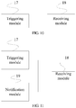
- FIG. 10 is a schematic structural diagram of a first embodiment of a base station according to the present invention. As shown in FIG. 10 , the base station includes:
- the embodiment is configured to execute the technical solution of the method embodiment as shown in FIG. 4 , where the implement principle and technical effects thereof are similar, and will not be repeated herein.
- FIG. 11 is a schematic structural diagram of a second embodiment of a base station according to the present invention. As shown in FIG. 11 , on the basis of the structure as shown in FIG. 10 , the user equipment according to the embodiment further includes:
- the receiving module 18 of the base station may specifically have two functions as follows:
- the receiving module 18 is specifically configured to receive a sounding signal transmitted by the at least one UE by adopting the mode of occupying the sounding signal resource in the time division manner and according to the transmitting sequence.
- the notification module 19 is further configured to transmit a high layer signaling to the at least one UE, where the high layer signaling includes a transmitting sequence of the at least one UE occupying the sounding signal resource in the time division manner.
- the embodiment is configured to execute the technical solution of the method embodiment as shown in FIG. 5 , where the implement principle and technical effects thereof are similar, and will not be repeated herein
- a third embodiment of a base station according to the present invention may adopt the base station structure as shown in FIG. 10 , in the base station of the embodiment: a triggering module 17 is configured to transmit a trigger message to a group of user equipments (UEs), where the trigger message includes instruction information, and the instruction information is used for instructing at least one UE to transmit a sounding signal; the trigger message further includes configuration information of a sounding signal resource; where the trigger message is carried by a high layer signaling, the high layer signaling includes instruction information; or the trigger message is carried by a physical downlink control channel (PDCCH) bearing downlink control information (DCI), where the DCI includes the instruction information.
- UEs user equipments
- the trigger message further includes configuration information of a sounding signal resource
- the trigger message is carried by a high layer signaling, the high layer signaling includes instruction information
- the trigger message is carried by a physical downlink control channel (PDCCH) bearing downlink control information (DCI), where the DCI includes the instruction information.
- a receiving module 18 is specifically configured to receive a sounding signal transmitted by the at least one UE on the sounding signal resource according to the instruction information.
- the receiving module 18 of the base station may specifically have two functions as follows:
- the receiving module 18 is specifically configured to receive a sounding signal transmitted by the at least one UE by adopting the mode of occupying the sounding signal resource in the time division manner and according to the transmitting sequence.
- the embodiment is configured to execute the technical solution of the method embodiment as shown in FIG. 6 , where the implement principle and technical effects thereof are similar, and will not be repeated herein.
- a base station to trigger at least one UE in a group of UEs to transmit a channel quality indicator (Channel Quality Indicator, abbreviated as CQI) or a precoding matrix indicator (Precoding Matrix Indicator, abbreviated as PMI) or a rank indicator (Rank indicator, abbreviated as RI).
- CQI Channel Quality Indicator
- PMI Precoding Matrix Indicator
- RI rank indicator
- the detailed embodiments of methods and apparatuses for triggering by a base station at least one UE in a group of UEs to transmit CQI/PMI/RI may be obtained by replacing the sounding signal, in the aforementioned embodiments of the methods for transmitting the sounding signal, the methods for receiving the sounding signal, the base stations and the UEs, into the CQI/PMI/RI.
- trigger modes may adopt:
- the above mode 2 may also be expanded to occupy more than 2 bits so as to represent more selections of CQI/PMI/RI feedback.
- embodiments of the present invention can enable an eNodeB to schedule, on a PDCCH, at least one UE in a group of UEs to feed back the CQI/PMI/RI, thereby improving the scheduling efficiency of the CQI/PMI/RI.
Landscapes
- Engineering & Computer Science (AREA)
- Signal Processing (AREA)
- Computer Networks & Wireless Communication (AREA)
- Mobile Radio Communication Systems (AREA)
Claims (16)
- Verfahren zum Senden eines Sondierungssignals, umfassend:Empfang (101, 202, 301) einer Auslösermeldung, die durch eine Basisstation gesendet wird, durch eine Benutzerausrüstung, UE, in einer Gruppe von UEs, wobei die Auslösermeldung Anweisungsinformationen umfasst und die Anweisungsinformationen verwendet werden, um die Gruppe von UEs anzuweisen, ein Sondierungssignal zu senden, und die Gruppe von Benutzerausrüstungen mindestens zwei Benutzerausrüstungen umfasst; undSenden (102, 203, 302) des Sondierungssignals durch die UE an die Basisstation den Anweisungsinformationen entsprechend;wobeidas Verfahren vor dem Empfang (202) der Auslösermeldung, die durch die Basisstation gesendet wird, durch die UE in der Gruppe von UEs, ferner umfasst:Empfang (201) einer Benachrichtigungsmeldung, die durch die Basisstation gesendet wird, durch die UE, wobei die Benachrichtigungsmeldung Konfigurationsinformationen einer Sondierungssignalressource für die Gruppe von UEs umfasst;wobei das Senden des Sondierungssignals an die Basisstation durch die UE den Anweisungsinformationen entsprechend umfasst: Senden (203, 302) des Sondierungssignals an die Basisstation durch die UE auf einer Sondierungssignalressource, die der UE den Anweisungsinformationen entsprechend entspricht,dadurch gekennzeichnet, dass die Sondierungssignalressource, die der UE entspricht, durch die UE auf Grundlage der Konfigurationsinformationen der Sondierungssignalressource einer gruppeninternen Anzahl der UE berechnet wird;wobei die Sondierungssignalressource, die der UE entspricht, mindestens entweder eine Frequenzbereichsstartposition, eine zyklische Verschiebung oder ein Übertragungskamm ist.
- Verfahren nach Anspruch 1, wobei die Auslösermeldung durch ein Hochschichtsignal getragen wird und das Hochschichtsignal Anweisungsinformationen umfasst; oder
die Auslösermeldung durch einen physischen Downlink-Steuerkanal, PDCCH, getragen wird, der Downlink-Steuerinformationen, DCI, trägt, wobei die DCI die Anweisungsinformationen umfassen. - Verfahren nach Anspruch 1, wobei das Senden des Sondierungssignals durch die UE an die Basisstation der Sondierungssignalressource umfasst:
Senden des Sondierungssignals durch die UE an die Basisstation durch Annahme eines Modus zur Belegung der Sondierungssignalressource in einer Zeitunterteilungsweise. - Verfahren nach Anspruch 3,
wobei
die Konfigurationsinformationen ferner eine Sendesequenz der Gruppe von UEs umfassen, die die Sondierungssignalressource in der Zeitunterteilungsweise belegen; oder
das Verfahren ferner umfasst: Empfang eines Hochschichtsignals, das durch die Basisstation gesendet wird, wobei das Hochschichtsignal eine Sendesequenz der Gruppe von UEs umfasst, die die Sondierungssignalressource in der Zeitunterteilungsweise belegen;
wobei das Senden des Sondierungssignals durch die UE an die Basisstation durch Annahme des Modus der Belegung der Sondierungssignalressource in der Zeitunterteilungsweise umfasst: Belegung der Sondierungssignalressource in der Zeitunterteilungsweise und Senden des Sondierungssignals an die Basisstation der Sendesequenz entsprechend. - Verfahren zum Empfang eines Sondierungssignals, umfassend:Senden (401, 502, 601) einer Auslösermeldung durch eine Basisstation, an eine Gruppe von Benutzerausrüstungen, UEs, wobei die Auslösermeldung Anweisungsinformationen umfasst und die Anweisungsinformationen verwendet werden, um die Gruppe von UEs anzuweisen, ein Sondierungssignal zu senden, und die Gruppe von Benutzerausrüstungen mindestens zwei Benutzerausrüstungen umfasst; undEmpfang (402, 503, 602) des Sondierungssignals, das durch die Gruppe von UEs den Anweisungsinformationen entsprechend gesendet wurde, durch die Basisstation;wobeivor dem Senden (502) der Auslösermeldung durch die Basisstation an die Gruppe von UEs das Verfahren ferner umfasst: Senden (501) einer Benachrichtigungsmeldung durch die Basisstation an die Gruppe von UEs, wobei die Benachrichtigungsmeldung Konfigurationsinformationen einer Sondierungssignalressource für die Gruppe von UEs umfasst;wobei der Empfang des Sondierungssignals, das durch die Gruppe von UEs den Anweisungsinformationen entsprechend gesendet wird, durch die Basisstation umfasst: Empfang (503, 602) des Sondierungssignals, das durch jede UE in der Gruppe von UEs an einer Sondierungssignalressource, die der jeweiligen UE entspricht, den Anweisungsinformationen entsprechend durch die Basisstation gesendet wird,dadurch gekennzeichnet, dass die Sondierungssignalressource, die der jeweiligen UE entspricht, durch die jeweilige UE auf Grundlage der Konfigurationsinformationen der Sondierungssignalressource einer gruppeninternen Anzahl der jeweiligen UE berechnet wird;wobei die Sondierungssignalressource, die der UE entspricht, mindestens entweder eine Frequenzbereichsstartposition, eine zyklische Verschiebung oder ein Übertragungskamm ist.
- Verfahren nach Anspruch 5, wobei die Auslösermeldung durch ein Hochschichtsignal getragen wird und das Hochschichtsignal Anweisungsinformationen umfasst; oder
die Auslösermeldung durch einen physischen Downlink-Steuerkanal, PDCCH, getragen wird, der Downlink-Steuerinformationen, DCI, trägt, wobei die DCI die Anweisungsinformationen umfassen. - Verfahren nach Anspruch 5, wobei der Empfang des Sondierungssignals, das durch die Gruppe von UEs an der Sondierungssignalressource den Anweisungsinformationen entsprechend gesendet wird, durch die Basisstation umfasst:
Empfang des Sondierungssignals, das durch die Gruppe von UEs gesendet wird, durch die Basisstation durch Annahme eines Modus zur Belegung der Sondierungssignalressource in einer Zeitunterteilungsweise. - Benutzerausrüstung, UE, umfassend:ein erstes Empfangsmodul (10), konfiguriert zum Empfang einer Auslösermeldung, die durch eine Basisstation gesendet wird, wobei die Auslösermeldung Anweisungsinformationen umfasst und die Anweisungsinformationen zum Anweisen einer Gruppe von UEs, ein Sondierungssignal zu senden, verwendet werden; undein Sendemodul (11), das konfiguriert ist, das Sondierungssignal den Anweisungsinformationen entsprechend an die Basisstation zu senden;wobeidie Benutzerausrüstung ferner ein zweites Empfangsmodul (12) umfasst, konfiguriert, eine Benachrichtigungsmeldung zu empfangen, die durch die Basisstation gesendet wird, bevor das erste Empfangsmodul (10) die Auslösermeldung empfängt, die durch die Basisstation gesendet wird, wobei die Benachrichtigungsmeldung Konfigurationsinformationen einer Sondierungssignalressource für die Gruppe von UEs umfasst;wobei das Sendemodul (11) speziell konfiguriert ist, das Sondierungssignal den Anweisungsinformationen entsprechend an die Basisstation an einer Sondierungssignalressource, die der UE entspricht, zu senden,dadurch gekennzeichnet, dass die Sondierungssignalressource, die der UE entspricht, durch die UE auf Grundlage der Konfigurationsinformationen der Sondierungssignalressource einer gruppeninternen Anzahl der UE berechnet wird;wobei die Sondierungssignalressource, die der UE entspricht, mindestens entweder eine Frequenzbereichsstartposition, eine zyklische Verschiebung oder ein Übertragungskamm ist.
- Benutzerausrüstung nach Anspruch 8, wobei die Auslösermeldung durch ein Hochschichtsignal getragen wird und das Hochschichtsignal Anweisungsinformationen umfasst; oder
die Auslösermeldung durch einen physischen Downlink-Steuerkanal, PDCCH, getragen wird, der Downlink-Steuerinformationen, DCI, trägt, wobei die DCI die Anweisungsinformationen umfassen. - Benutzerausrüstung nach Anspruch 8, wobei die Mitteilungsmeldung durch ein Hochschichtsignal getragen wird und das Hochschichtsignal Konfigurationsinformationen umfasst; oder
die Benachrichtigungsmeldung durch einen PDCCH getragen wird, der DCI trägt, und die DCI die Konfigurationsinformationen umfassen. - Benutzerausrüstung nach Anspruch 8 oder 10, wobei das Sendemodul speziell konfiguriert ist, das Sondierungssignal an die Basisstation zu senden, indem es einen Modus der Belegung der Sondierungssignalressource in einer Zeitunterteilungsweise annimmt.
- Benutzerausrüstung nach Anspruch 11,
wobei
die Konfigurationsinformationen ferner eine Sendesequenz der Gruppe von UEs umfassen, die die Sondierungssignalressource in der Zeitunterteilungsweise belegen; oder
das zweite Empfangsmodul ebenfalls konfiguriert ist, ein Hochschichtsignal zu empfangen, das durch die Basisstation gesendet wird, wobei das Hochschichtsignal eine Sendesequenz der mindestens einen UE umfasst, die die Sondierungssignalressource in der Zeitunterteilungsweise belegt;
wobei das Sendemodul speziell konfiguriert ist, die Sondierungssignalressource in der Zeitunterteilungsweise zu belegen und das Sondierungssignal der Sendesequenz entsprechend an die Basisstation zu senden. - Basisstation, umfassend:ein Auslösemodul (17), konfiguriert zum Senden einer Auslösermeldung an eine Gruppe von Benutzerausrüstungen, UEs, wobei die Auslösermeldung Anweisungsinformationen umfasst und die Anweisungsinformationen zum Anweisen der Gruppe von UEs, ein Sondierungssignal zu senden, verwendet werden; undein Empfangsmodul (18), konfiguriert zum Empfang des Sondierungssignals, das durch die Gruppe von UEs gesendet wird, den Anweisungsinformationen entsprechend;wobeidie Basisstation ferner ein Mitteilungsmodul (19) umfasst, das zum Senden einer Benachrichtigungsmeldung an die Gruppe von UEs konfiguriert ist, wobei die Benachrichtigungsmeldung Konfigurationsinformationen einer Sondierungssignalressource für die Gruppe von UEs umfasst;wobei das Empfangsmodul (18) speziell konfiguriert ist, das Sondierungssignal zu empfangen, das durch jede UE in der Gruppe von UEs an einer Sondierungssignalressource, die der jeweiligen UE entspricht, den Anweisungsinformationen entsprechend gesendet wird,dadurch gekennzeichnet, dass die Sondierungssignalressource, die der jeweiligen UE entspricht, durch die jeweilige UE auf Grundlage der Konfigurationsinformationen der Sondierungssignalressource einer gruppeninternen Anzahl der jeweiligen UE berechnet wird;wobei die Sondierungssignalressource, die der UE entspricht, mindestens entweder eine Frequenzbereichsstartposition, eine zyklische Verschiebung oder ein Übertragungskamm ist.
- Basisstation nach Anspruch 13, wobei die Auslösermeldung durch ein Hochschichtsignal getragen wird und das Hochschichtsignal Anweisungsinformationen umfasst; oder
die Auslösermeldung durch einen physischen Downlink-Steuerkanal, PDCCH, getragen wird, der Downlink-Steuerinformationen, DCI, trägt, wobei die DCI die Anweisungsinformationen umfassen. - Basisstation nach Anspruch 13, wobei das Sendemodul speziell konfiguriert ist, das Sondierungssignal, das von der Gruppe UEs gesendet wird, zu empfangen, indem es einen Modus der Belegung der Sondierungssignalressource in einer Zeitunterteilungsweise annimmt.
- Basisstation nach Anspruch 15, wobei,
die Konfigurationsinformationen ferner eine Sendesequenz der Gruppe von UEs umfassen, die die Sondierungssignalressource in der Zeitunterteilungsweise belegen; oder
das Mitteilungsmodul ebenfalls konfiguriert ist, ein Hochschichtsignal an die Gruppe von UEs zu senden, wobei das Hochschichtsignal eine Sendesequenz der Gruppe von UEs umfasst, die die Sondierungssignalressource in der Zeitunterteilungsweise belegen.
Priority Applications (1)
| Application Number | Priority Date | Filing Date | Title |
|---|---|---|---|
| EP18207674.5A EP3541003B1 (de) | 2012-08-15 | 2012-08-15 | Verfahren zum senden und empfangen von peilungssignalen, basisstation und benutzergerät |
Applications Claiming Priority (1)
| Application Number | Priority Date | Filing Date | Title |
|---|---|---|---|
| PCT/CN2012/080160 WO2014026335A1 (zh) | 2012-08-15 | 2012-08-15 | 探测信号发送和接收方法、基站和用户设备 |
Related Child Applications (1)
| Application Number | Title | Priority Date | Filing Date |
|---|---|---|---|
| EP18207674.5A Division EP3541003B1 (de) | 2012-08-15 | 2012-08-15 | Verfahren zum senden und empfangen von peilungssignalen, basisstation und benutzergerät |
Publications (3)
| Publication Number | Publication Date |
|---|---|
| EP2876952A1 EP2876952A1 (de) | 2015-05-27 |
| EP2876952A4 EP2876952A4 (de) | 2015-10-14 |
| EP2876952B1 true EP2876952B1 (de) | 2018-12-05 |
Family
ID=50101193
Family Applications (2)
| Application Number | Title | Priority Date | Filing Date |
|---|---|---|---|
| EP12882935.5A Active EP2876952B1 (de) | 2012-08-15 | 2012-08-15 | Erkennungssignalsende- und -empfangsverfahren, basisstation und benutzervorrichtung |
| EP18207674.5A Active EP3541003B1 (de) | 2012-08-15 | 2012-08-15 | Verfahren zum senden und empfangen von peilungssignalen, basisstation und benutzergerät |
Family Applications After (1)
| Application Number | Title | Priority Date | Filing Date |
|---|---|---|---|
| EP18207674.5A Active EP3541003B1 (de) | 2012-08-15 | 2012-08-15 | Verfahren zum senden und empfangen von peilungssignalen, basisstation und benutzergerät |
Country Status (5)
| Country | Link |
|---|---|
| US (2) | US9609643B2 (de) |
| EP (2) | EP2876952B1 (de) |
| CN (3) | CN109560911B (de) |
| ES (1) | ES2711337T3 (de) |
| WO (1) | WO2014026335A1 (de) |
Families Citing this family (8)
| Publication number | Priority date | Publication date | Assignee | Title |
|---|---|---|---|---|
| EP2876952B1 (de) * | 2012-08-15 | 2018-12-05 | Huawei Technologies Co., Ltd. | Erkennungssignalsende- und -empfangsverfahren, basisstation und benutzervorrichtung |
| EP3014786B1 (de) * | 2013-06-26 | 2019-11-20 | LG Electronics Inc. | Gruppierungsbasierte referenzsignalübertragung für massives mimo-schema |
| WO2015199603A1 (en) * | 2014-06-24 | 2015-12-30 | Telefonaktiebolaget L M Ericsson (Publ) | Method and apparatuses for operating a wireless communication network |
| CN107820698A (zh) * | 2015-07-24 | 2018-03-20 | 哈里伯顿能源服务公司 | 用于进行信道映射和均衡器初始化的跳频探测器信号 |
| CN106254047B (zh) * | 2015-08-31 | 2019-12-06 | 北京智谷技术服务有限公司 | 探测参考信号调度方法、发送方法、及其装置 |
| US10462676B2 (en) * | 2017-04-10 | 2019-10-29 | Qualcomm Incorporated | Inter-operator SRS resource coordination in SDM-comp |
| CN115552975B (zh) * | 2020-03-20 | 2025-09-02 | 高通股份有限公司 | 低复杂度物理下行链路控制信道 |
| WO2023137698A1 (en) * | 2022-01-21 | 2023-07-27 | Zte Corporation | Systems and methods for simultaneous uplink transmissions based on multi-trp operation |
Family Cites Families (18)
| Publication number | Priority date | Publication date | Assignee | Title |
|---|---|---|---|---|
| KR100984819B1 (ko) * | 2005-10-07 | 2010-10-04 | 인터디지탈 테크날러지 코포레이션 | 고속 다운링크 및 업링크를 지원하기 위한 제어 정보의제공 방법 및 시스템 |
| CN101404817B (zh) * | 2008-11-24 | 2010-09-29 | 华为技术有限公司 | Srs带宽配置的方法、系统及装置 |
| US20100215011A1 (en) * | 2009-02-26 | 2010-08-26 | Interdigital Patent Holdings, Inc. | Method and apparatus for switching a resource assignment mode for a plurality of component carriers |
| US8724488B2 (en) * | 2009-03-17 | 2014-05-13 | Interdigital Patent Holdings, Inc. | Method and apparatus for power control of sounding reference signal (SRS) transmission |
| CN106850023B (zh) * | 2009-03-22 | 2020-09-15 | Lg电子株式会社 | 使用多个天线的信道探测方法以及用于其的装置 |
| JP2011035785A (ja) * | 2009-08-04 | 2011-02-17 | Sharp Corp | 無線通信システム、移動局装置および基地局装置 |
| KR101893460B1 (ko) * | 2009-09-28 | 2018-08-31 | 삼성전자주식회사 | 물리 하향링크 제어 채널의 확장 |
| US9055576B2 (en) * | 2009-10-08 | 2015-06-09 | Qualcomm Incorporated | Uplink resource allocation for LTE advanced |
| CN102075298B (zh) * | 2009-11-19 | 2014-04-30 | 华为技术有限公司 | 一种用户设备ue发送探测信号的方法、用户设备、基站 |
| CN102714869B (zh) * | 2010-01-08 | 2016-04-06 | 夏普株式会社 | 用于探测参考信号传输的移动通信方法和系统以及基站、用户设备和其中的集成电路 |
| US8611442B2 (en) * | 2010-04-06 | 2013-12-17 | Motorola Mobility Llc | Method and apparatus for channel sounding in an orthogonal frequency division multiplexing communication system |
| US9107208B2 (en) * | 2010-05-12 | 2015-08-11 | Lg Electronics Inc. | Method for transmitting an SRS-triggering-based SRS in a wireless communication system |
| US8855053B2 (en) * | 2010-06-18 | 2014-10-07 | Mediatek Inc. | Sounding mechanism and configuration under carrier aggregation |
| TWI462622B (zh) * | 2010-06-18 | 2014-11-21 | Mediatek Inc | 載波聚合下之探測方法以及使用者設備 |
| CN102333341A (zh) * | 2010-07-13 | 2012-01-25 | 华为技术有限公司 | 数据传输方法、用户设备和基站 |
| US9350506B2 (en) * | 2010-09-30 | 2016-05-24 | Qualcomm Incorporated | Aperiodic SRS for carrier aggregation |
| CN102594538B (zh) * | 2011-03-25 | 2017-03-01 | 北京新岸线移动多媒体技术有限公司 | 一种无线通信方法、系统与设备 |
| EP2876952B1 (de) * | 2012-08-15 | 2018-12-05 | Huawei Technologies Co., Ltd. | Erkennungssignalsende- und -empfangsverfahren, basisstation und benutzervorrichtung |
-
2012
- 2012-08-15 EP EP12882935.5A patent/EP2876952B1/de active Active
- 2012-08-15 CN CN201910002045.5A patent/CN109560911B/zh not_active Expired - Fee Related
- 2012-08-15 CN CN201280004290.6A patent/CN103828452B/zh active Active
- 2012-08-15 CN CN201910002105.3A patent/CN109617661A/zh active Pending
- 2012-08-15 WO PCT/CN2012/080160 patent/WO2014026335A1/zh not_active Ceased
- 2012-08-15 EP EP18207674.5A patent/EP3541003B1/de active Active
- 2012-08-15 ES ES12882935T patent/ES2711337T3/es active Active
-
2015
- 2015-02-11 US US14/619,676 patent/US9609643B2/en not_active Ceased
-
2019
- 2019-03-22 US US16/361,219 patent/USRE48292E1/en active Active
Non-Patent Citations (1)
| Title |
|---|
| None * |
Also Published As
| Publication number | Publication date |
|---|---|
| EP3541003A1 (de) | 2019-09-18 |
| CN103828452B (zh) | 2019-01-25 |
| EP3541003B1 (de) | 2022-01-05 |
| CN103828452A (zh) | 2014-05-28 |
| CN109617661A (zh) | 2019-04-12 |
| CN109560911B (zh) | 2022-07-19 |
| US20150156756A1 (en) | 2015-06-04 |
| ES2711337T3 (es) | 2019-05-03 |
| WO2014026335A1 (zh) | 2014-02-20 |
| USRE48292E1 (en) | 2020-10-27 |
| EP2876952A1 (de) | 2015-05-27 |
| CN109560911A (zh) | 2019-04-02 |
| US9609643B2 (en) | 2017-03-28 |
| EP2876952A4 (de) | 2015-10-14 |
Similar Documents
| Publication | Publication Date | Title |
|---|---|---|
| USRE48292E1 (en) | Method for transmitting and receiving sounding signal, base station and user equipment | |
| JP6082121B2 (ja) | 情報送信方法、ユーザ装置及び基地局 | |
| US9681427B2 (en) | Method for transmitting feedback information for downlink data, terminal, and base station | |
| CN102104972B (zh) | Uci信息传输的配置方法和设备 | |
| US8879494B2 (en) | Method and system for non-periodic feedback in carrier aggregation scenario | |
| CN108900288B (zh) | 信道状态信息的传输方法、装置及计算机可读存储介质 | |
| EP3353936B1 (de) | Bestimmung der kanalstatusinformation für verbesserte trägeraggregation | |
| US12010199B2 (en) | Information transmission method, apparatus, and system | |
| EP3188563A1 (de) | Verfahren und vorrichtung zur steuerung eines sekundären trägers in einer asymmetrischen uplink-trägeraggregation | |
| US11284390B2 (en) | Data communication method, terminal device, and network device | |
| EP3745792B1 (de) | Kommunikationsverfahren und -vorrichtung | |
| WO2015173632A1 (en) | Method of reducing impact of d2d in-band interference on cellular transmission | |
| US9749987B2 (en) | Mobile communication method and radio base station | |
| EP3456138B1 (de) | Verfahren und vorrichtung zur implementierung einer präambelzonenauswahl | |
| EP3051738A1 (de) | Verfahren zur überwachung eines benutzerendgerätespezifischen suchraums, benutzergerät, knoten und computerprogrammprodukt |
Legal Events
| Date | Code | Title | Description |
|---|---|---|---|
| PUAI | Public reference made under article 153(3) epc to a published international application that has entered the european phase |
Free format text: ORIGINAL CODE: 0009012 |
|
| 17P | Request for examination filed |
Effective date: 20150223 |
|
| AK | Designated contracting states |
Kind code of ref document: A1 Designated state(s): AL AT BE BG CH CY CZ DE DK EE ES FI FR GB GR HR HU IE IS IT LI LT LU LV MC MK MT NL NO PL PT RO RS SE SI SK SM TR |
|
| AX | Request for extension of the european patent |
Extension state: BA ME |
|
| REG | Reference to a national code |
Ref country code: DE Ref legal event code: R079 Ref document number: 602012054515 Country of ref document: DE Free format text: PREVIOUS MAIN CLASS: H04W0068000000 Ipc: H04L0005000000 |
|
| RA4 | Supplementary search report drawn up and despatched (corrected) |
Effective date: 20150915 |
|
| RIC1 | Information provided on ipc code assigned before grant |
Ipc: H04L 5/00 20060101AFI20150909BHEP |
|
| DAX | Request for extension of the european patent (deleted) | ||
| STAA | Information on the status of an ep patent application or granted ep patent |
Free format text: STATUS: EXAMINATION IS IN PROGRESS |
|
| 17Q | First examination report despatched |
Effective date: 20180202 |
|
| GRAP | Despatch of communication of intention to grant a patent |
Free format text: ORIGINAL CODE: EPIDOSNIGR1 |
|
| STAA | Information on the status of an ep patent application or granted ep patent |
Free format text: STATUS: GRANT OF PATENT IS INTENDED |
|
| INTG | Intention to grant announced |
Effective date: 20180622 |
|
| GRAS | Grant fee paid |
Free format text: ORIGINAL CODE: EPIDOSNIGR3 |
|
| GRAA | (expected) grant |
Free format text: ORIGINAL CODE: 0009210 |
|
| GRAA | (expected) grant |
Free format text: ORIGINAL CODE: 0009210 |
|
| STAA | Information on the status of an ep patent application or granted ep patent |
Free format text: STATUS: THE PATENT HAS BEEN GRANTED |
|
| AK | Designated contracting states |
Kind code of ref document: B1 Designated state(s): AL AT BE BG CH CY CZ DE DK EE ES FI FR GB GR HR HU IE IS IT LI LT LU LV MC MK MT NL NO PL PT RO RS SE SI SK SM TR |
|
| REG | Reference to a national code |
Ref country code: GB Ref legal event code: FG4D |
|
| REG | Reference to a national code |
Ref country code: CH Ref legal event code: EP |
|
| REG | Reference to a national code |
Ref country code: AT Ref legal event code: REF Ref document number: 1074435 Country of ref document: AT Kind code of ref document: T Effective date: 20181215 |
|
| REG | Reference to a national code |
Ref country code: IE Ref legal event code: FG4D |
|
| REG | Reference to a national code |
Ref country code: DE Ref legal event code: R096 Ref document number: 602012054515 Country of ref document: DE |
|
| REG | Reference to a national code |
Ref country code: NL Ref legal event code: FP |
|
| REG | Reference to a national code |
Ref country code: AT Ref legal event code: MK05 Ref document number: 1074435 Country of ref document: AT Kind code of ref document: T Effective date: 20181205 |
|
| REG | Reference to a national code |
Ref country code: LT Ref legal event code: MG4D |
|
| PG25 | Lapsed in a contracting state [announced via postgrant information from national office to epo] |
Ref country code: AT Free format text: LAPSE BECAUSE OF FAILURE TO SUBMIT A TRANSLATION OF THE DESCRIPTION OR TO PAY THE FEE WITHIN THE PRESCRIBED TIME-LIMIT Effective date: 20181205 Ref country code: BG Free format text: LAPSE BECAUSE OF FAILURE TO SUBMIT A TRANSLATION OF THE DESCRIPTION OR TO PAY THE FEE WITHIN THE PRESCRIBED TIME-LIMIT Effective date: 20190305 Ref country code: LV Free format text: LAPSE BECAUSE OF FAILURE TO SUBMIT A TRANSLATION OF THE DESCRIPTION OR TO PAY THE FEE WITHIN THE PRESCRIBED TIME-LIMIT Effective date: 20181205 Ref country code: NO Free format text: LAPSE BECAUSE OF FAILURE TO SUBMIT A TRANSLATION OF THE DESCRIPTION OR TO PAY THE FEE WITHIN THE PRESCRIBED TIME-LIMIT Effective date: 20190305 Ref country code: HR Free format text: LAPSE BECAUSE OF FAILURE TO SUBMIT A TRANSLATION OF THE DESCRIPTION OR TO PAY THE FEE WITHIN THE PRESCRIBED TIME-LIMIT Effective date: 20181205 Ref country code: LT Free format text: LAPSE BECAUSE OF FAILURE TO SUBMIT A TRANSLATION OF THE DESCRIPTION OR TO PAY THE FEE WITHIN THE PRESCRIBED TIME-LIMIT Effective date: 20181205 |
|
| REG | Reference to a national code |
Ref country code: ES Ref legal event code: FG2A Ref document number: 2711337 Country of ref document: ES Kind code of ref document: T3 Effective date: 20190503 |
|
| PG25 | Lapsed in a contracting state [announced via postgrant information from national office to epo] |
Ref country code: SE Free format text: LAPSE BECAUSE OF FAILURE TO SUBMIT A TRANSLATION OF THE DESCRIPTION OR TO PAY THE FEE WITHIN THE PRESCRIBED TIME-LIMIT Effective date: 20181205 Ref country code: AL Free format text: LAPSE BECAUSE OF FAILURE TO SUBMIT A TRANSLATION OF THE DESCRIPTION OR TO PAY THE FEE WITHIN THE PRESCRIBED TIME-LIMIT Effective date: 20181205 Ref country code: RS Free format text: LAPSE BECAUSE OF FAILURE TO SUBMIT A TRANSLATION OF THE DESCRIPTION OR TO PAY THE FEE WITHIN THE PRESCRIBED TIME-LIMIT Effective date: 20181205 Ref country code: GR Free format text: LAPSE BECAUSE OF FAILURE TO SUBMIT A TRANSLATION OF THE DESCRIPTION OR TO PAY THE FEE WITHIN THE PRESCRIBED TIME-LIMIT Effective date: 20190306 |
|
| PG25 | Lapsed in a contracting state [announced via postgrant information from national office to epo] |
Ref country code: PL Free format text: LAPSE BECAUSE OF FAILURE TO SUBMIT A TRANSLATION OF THE DESCRIPTION OR TO PAY THE FEE WITHIN THE PRESCRIBED TIME-LIMIT Effective date: 20181205 Ref country code: CZ Free format text: LAPSE BECAUSE OF FAILURE TO SUBMIT A TRANSLATION OF THE DESCRIPTION OR TO PAY THE FEE WITHIN THE PRESCRIBED TIME-LIMIT Effective date: 20181205 Ref country code: PT Free format text: LAPSE BECAUSE OF FAILURE TO SUBMIT A TRANSLATION OF THE DESCRIPTION OR TO PAY THE FEE WITHIN THE PRESCRIBED TIME-LIMIT Effective date: 20190405 Ref country code: IT Free format text: LAPSE BECAUSE OF FAILURE TO SUBMIT A TRANSLATION OF THE DESCRIPTION OR TO PAY THE FEE WITHIN THE PRESCRIBED TIME-LIMIT Effective date: 20181205 |
|
| PG25 | Lapsed in a contracting state [announced via postgrant information from national office to epo] |
Ref country code: EE Free format text: LAPSE BECAUSE OF FAILURE TO SUBMIT A TRANSLATION OF THE DESCRIPTION OR TO PAY THE FEE WITHIN THE PRESCRIBED TIME-LIMIT Effective date: 20181205 Ref country code: SM Free format text: LAPSE BECAUSE OF FAILURE TO SUBMIT A TRANSLATION OF THE DESCRIPTION OR TO PAY THE FEE WITHIN THE PRESCRIBED TIME-LIMIT Effective date: 20181205 Ref country code: IS Free format text: LAPSE BECAUSE OF FAILURE TO SUBMIT A TRANSLATION OF THE DESCRIPTION OR TO PAY THE FEE WITHIN THE PRESCRIBED TIME-LIMIT Effective date: 20190405 Ref country code: RO Free format text: LAPSE BECAUSE OF FAILURE TO SUBMIT A TRANSLATION OF THE DESCRIPTION OR TO PAY THE FEE WITHIN THE PRESCRIBED TIME-LIMIT Effective date: 20181205 Ref country code: SK Free format text: LAPSE BECAUSE OF FAILURE TO SUBMIT A TRANSLATION OF THE DESCRIPTION OR TO PAY THE FEE WITHIN THE PRESCRIBED TIME-LIMIT Effective date: 20181205 |
|
| REG | Reference to a national code |
Ref country code: DE Ref legal event code: R097 Ref document number: 602012054515 Country of ref document: DE |
|
| PLBE | No opposition filed within time limit |
Free format text: ORIGINAL CODE: 0009261 |
|
| STAA | Information on the status of an ep patent application or granted ep patent |
Free format text: STATUS: NO OPPOSITION FILED WITHIN TIME LIMIT |
|
| PG25 | Lapsed in a contracting state [announced via postgrant information from national office to epo] |
Ref country code: SI Free format text: LAPSE BECAUSE OF FAILURE TO SUBMIT A TRANSLATION OF THE DESCRIPTION OR TO PAY THE FEE WITHIN THE PRESCRIBED TIME-LIMIT Effective date: 20181205 Ref country code: DK Free format text: LAPSE BECAUSE OF FAILURE TO SUBMIT A TRANSLATION OF THE DESCRIPTION OR TO PAY THE FEE WITHIN THE PRESCRIBED TIME-LIMIT Effective date: 20181205 |
|
| 26N | No opposition filed |
Effective date: 20190906 |
|
| PG25 | Lapsed in a contracting state [announced via postgrant information from national office to epo] |
Ref country code: TR Free format text: LAPSE BECAUSE OF FAILURE TO SUBMIT A TRANSLATION OF THE DESCRIPTION OR TO PAY THE FEE WITHIN THE PRESCRIBED TIME-LIMIT Effective date: 20181205 |
|
| PG25 | Lapsed in a contracting state [announced via postgrant information from national office to epo] |
Ref country code: CH Free format text: LAPSE BECAUSE OF NON-PAYMENT OF DUE FEES Effective date: 20190831 Ref country code: LU Free format text: LAPSE BECAUSE OF NON-PAYMENT OF DUE FEES Effective date: 20190815 Ref country code: LI Free format text: LAPSE BECAUSE OF NON-PAYMENT OF DUE FEES Effective date: 20190831 Ref country code: MC Free format text: LAPSE BECAUSE OF FAILURE TO SUBMIT A TRANSLATION OF THE DESCRIPTION OR TO PAY THE FEE WITHIN THE PRESCRIBED TIME-LIMIT Effective date: 20181205 |
|
| REG | Reference to a national code |
Ref country code: BE Ref legal event code: MM Effective date: 20190831 |
|
| PG25 | Lapsed in a contracting state [announced via postgrant information from national office to epo] |
Ref country code: FR Free format text: LAPSE BECAUSE OF NON-PAYMENT OF DUE FEES Effective date: 20190831 Ref country code: IE Free format text: LAPSE BECAUSE OF NON-PAYMENT OF DUE FEES Effective date: 20190815 |
|
| PG25 | Lapsed in a contracting state [announced via postgrant information from national office to epo] |
Ref country code: BE Free format text: LAPSE BECAUSE OF NON-PAYMENT OF DUE FEES Effective date: 20190831 |
|
| PG25 | Lapsed in a contracting state [announced via postgrant information from national office to epo] |
Ref country code: CY Free format text: LAPSE BECAUSE OF FAILURE TO SUBMIT A TRANSLATION OF THE DESCRIPTION OR TO PAY THE FEE WITHIN THE PRESCRIBED TIME-LIMIT Effective date: 20181205 |
|
| PG25 | Lapsed in a contracting state [announced via postgrant information from national office to epo] |
Ref country code: HU Free format text: LAPSE BECAUSE OF FAILURE TO SUBMIT A TRANSLATION OF THE DESCRIPTION OR TO PAY THE FEE WITHIN THE PRESCRIBED TIME-LIMIT; INVALID AB INITIO Effective date: 20120815 Ref country code: MT Free format text: LAPSE BECAUSE OF FAILURE TO SUBMIT A TRANSLATION OF THE DESCRIPTION OR TO PAY THE FEE WITHIN THE PRESCRIBED TIME-LIMIT Effective date: 20181205 |
|
| PG25 | Lapsed in a contracting state [announced via postgrant information from national office to epo] |
Ref country code: MK Free format text: LAPSE BECAUSE OF FAILURE TO SUBMIT A TRANSLATION OF THE DESCRIPTION OR TO PAY THE FEE WITHIN THE PRESCRIBED TIME-LIMIT Effective date: 20181205 |
|
| P01 | Opt-out of the competence of the unified patent court (upc) registered |
Free format text: CASE NUMBER: UPC_APP_329315/2023 Effective date: 20230524 |
|
| PGFP | Annual fee paid to national office [announced via postgrant information from national office to epo] |
Ref country code: NL Payment date: 20250704 Year of fee payment: 14 |
|
| PGFP | Annual fee paid to national office [announced via postgrant information from national office to epo] |
Ref country code: ES Payment date: 20250903 Year of fee payment: 14 Ref country code: FI Payment date: 20250814 Year of fee payment: 14 |
|
| PGFP | Annual fee paid to national office [announced via postgrant information from national office to epo] |
Ref country code: DE Payment date: 20250702 Year of fee payment: 14 |
|
| PGFP | Annual fee paid to national office [announced via postgrant information from national office to epo] |
Ref country code: GB Payment date: 20250703 Year of fee payment: 14 |