EP2876961A1 - Endgerätevorrichtung, basisstationsvorrichtung, kommunikationsverfahren und integrierte schaltung - Google Patents
Endgerätevorrichtung, basisstationsvorrichtung, kommunikationsverfahren und integrierte schaltung Download PDFInfo
- Publication number
- EP2876961A1 EP2876961A1 EP13822830.9A EP13822830A EP2876961A1 EP 2876961 A1 EP2876961 A1 EP 2876961A1 EP 13822830 A EP13822830 A EP 13822830A EP 2876961 A1 EP2876961 A1 EP 2876961A1
- Authority
- EP
- European Patent Office
- Prior art keywords
- cell
- reference signals
- base station
- control information
- specific reference
- Prior art date
- Legal status (The legal status is an assumption and is not a legal conclusion. Google has not performed a legal analysis and makes no representation as to the accuracy of the status listed.)
- Granted
Links
Images


Classifications
-
- H—ELECTRICITY
- H04—ELECTRIC COMMUNICATION TECHNIQUE
- H04L—TRANSMISSION OF DIGITAL INFORMATION, e.g. TELEGRAPHIC COMMUNICATION
- H04L5/00—Arrangements affording multiple use of the transmission path
- H04L5/003—Arrangements for allocating sub-channels of the transmission path
- H04L5/0044—Allocation of payload; Allocation of data channels, e.g. PDSCH or PUSCH
-
- H—ELECTRICITY
- H04—ELECTRIC COMMUNICATION TECHNIQUE
- H04L—TRANSMISSION OF DIGITAL INFORMATION, e.g. TELEGRAPHIC COMMUNICATION
- H04L1/00—Arrangements for detecting or preventing errors in the information received
- H04L1/004—Arrangements for detecting or preventing errors in the information received by using forward error control
- H04L1/0045—Arrangements at the receiver end
- H04L1/0046—Code rate detection or code type detection
-
- H—ELECTRICITY
- H04—ELECTRIC COMMUNICATION TECHNIQUE
- H04L—TRANSMISSION OF DIGITAL INFORMATION, e.g. TELEGRAPHIC COMMUNICATION
- H04L1/00—Arrangements for detecting or preventing errors in the information received
- H04L1/004—Arrangements for detecting or preventing errors in the information received by using forward error control
- H04L1/0056—Systems characterized by the type of code used
- H04L1/0067—Rate matching
-
- H—ELECTRICITY
- H04—ELECTRIC COMMUNICATION TECHNIQUE
- H04L—TRANSMISSION OF DIGITAL INFORMATION, e.g. TELEGRAPHIC COMMUNICATION
- H04L1/00—Arrangements for detecting or preventing errors in the information received
- H04L1/004—Arrangements for detecting or preventing errors in the information received by using forward error control
- H04L1/0072—Error control for data other than payload data, e.g. control data
-
- H—ELECTRICITY
- H04—ELECTRIC COMMUNICATION TECHNIQUE
- H04L—TRANSMISSION OF DIGITAL INFORMATION, e.g. TELEGRAPHIC COMMUNICATION
- H04L5/00—Arrangements affording multiple use of the transmission path
- H04L5/003—Arrangements for allocating sub-channels of the transmission path
- H04L5/0048—Allocation of pilot signals, i.e. of signals known to the receiver
- H04L5/005—Allocation of pilot signals, i.e. of signals known to the receiver of common pilots, i.e. pilots destined for multiple users or terminals
-
- H—ELECTRICITY
- H04—ELECTRIC COMMUNICATION TECHNIQUE
- H04L—TRANSMISSION OF DIGITAL INFORMATION, e.g. TELEGRAPHIC COMMUNICATION
- H04L5/00—Arrangements affording multiple use of the transmission path
- H04L5/003—Arrangements for allocating sub-channels of the transmission path
- H04L5/0048—Allocation of pilot signals, i.e. of signals known to the receiver
- H04L5/0051—Allocation of pilot signals, i.e. of signals known to the receiver of dedicated pilots, i.e. pilots destined for a single user or terminal
-
- H—ELECTRICITY
- H04—ELECTRIC COMMUNICATION TECHNIQUE
- H04L—TRANSMISSION OF DIGITAL INFORMATION, e.g. TELEGRAPHIC COMMUNICATION
- H04L5/00—Arrangements affording multiple use of the transmission path
- H04L5/0091—Signalling for the administration of the divided path, e.g. signalling of configuration information
-
- H—ELECTRICITY
- H04—ELECTRIC COMMUNICATION TECHNIQUE
- H04W—WIRELESS COMMUNICATION NETWORKS
- H04W72/00—Local resource management
- H04W72/04—Wireless resource allocation
- H04W72/044—Wireless resource allocation based on the type of the allocated resource
- H04W72/0446—Resources in time domain, e.g. slots or frames
-
- H—ELECTRICITY
- H04—ELECTRIC COMMUNICATION TECHNIQUE
- H04W—WIRELESS COMMUNICATION NETWORKS
- H04W72/00—Local resource management
- H04W72/12—Wireless traffic scheduling
-
- H—ELECTRICITY
- H04—ELECTRIC COMMUNICATION TECHNIQUE
- H04W—WIRELESS COMMUNICATION NETWORKS
- H04W72/00—Local resource management
- H04W72/20—Control channels or signalling for resource management
- H04W72/23—Control channels or signalling for resource management in the downlink direction of a wireless link, i.e. towards a terminal
-
- H—ELECTRICITY
- H04—ELECTRIC COMMUNICATION TECHNIQUE
- H04L—TRANSMISSION OF DIGITAL INFORMATION, e.g. TELEGRAPHIC COMMUNICATION
- H04L1/00—Arrangements for detecting or preventing errors in the information received
- H04L1/004—Arrangements for detecting or preventing errors in the information received by using forward error control
- H04L1/0056—Systems characterized by the type of code used
- H04L1/0067—Rate matching
- H04L1/0068—Rate matching by puncturing
-
- H—ELECTRICITY
- H04—ELECTRIC COMMUNICATION TECHNIQUE
- H04L—TRANSMISSION OF DIGITAL INFORMATION, e.g. TELEGRAPHIC COMMUNICATION
- H04L5/00—Arrangements affording multiple use of the transmission path
- H04L5/003—Arrangements for allocating sub-channels of the transmission path
- H04L5/0058—Allocation criteria
- H04L5/0073—Allocation arrangements that take into account other cell interferences
Definitions
- the present invention relates to a terminal device, a base station device, a communication method, and an integrated circuit.
- each of base station devices and terminal devices includes single or plural transmit-receive antenna, and a multiple-input multiple-output (MIMO) technology is used, thereby enabling realization of high speed data transmission.
- LTE Long Term Evolution
- LTE-A LTE-Advanced
- WiMAX Worldwide Interoperability for Microwave Access
- MIMO multiple-input multiple-output
- HetNet heterogeneous network deployment
- RRH remote radio head
- the base station device and the terminal device transmit and receive downlink data by a physical downlink shared channel (PDSCH) based on resource elements to which cell-specific reference signals are mapped (NPL 1).
- PDSCH physical downlink shared channel
- NPL 1 PDSCH mapping issues in CoMP; 3GPP TSG RAN WG1 meeting #69 Rl-122603, May 21th-25th, 2012 .
- the present invention has been made in consideration of the above problem, and an object thereof is to provide a terminal device, a base station device, a communication method, and an integrated circuit that allow a base station device and a terminal device to transmit and receive downlink data based on resource elements to which a physical signal or a physical channel is mapped and to perform efficient communication.
- the present invention allows a base station device and a mobile station device to transmit and receive downlink data based on resource elements to which a physical signal or a physical channel is mapped and to perform efficient communication.
- a radio communication system in the embodiment of the present invention includes a primary base station (also referred to as macro base station, first base station, first communication device, serving base station, anchor base station, or primary cell) and a secondary base station (also referred to as RRH, pico base station, femto base station, Home eNodeB, second base station device, second communication device, cooperative base station group, cooperative base station set, cooperative base station, or secondary cell) as a base station device (also referred to as base station, transmitting device, cell, serving cell, transmitting station, transmitting point, transmit antenna group, transmit antenna port group, or eNodeB).
- the radio communication system includes a mobile station device (also referred to as terminal, terminal device, mobile terminal, receiving device, receiving point, receiving terminal, third communication device, receive antenna group, receive antenna port group, or user equipment (UE)).
- UE user equipment
- heterogeneous network deployment may be applied to the primary base station and the secondary base station, a unit or whole of coverage of the secondary base station may be included in coverage of the primary base station.
- the secondary base station may be plural secondary base stations.
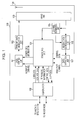
- Fig. 1 is a schematic block diagram that illustrates a configuration of the base station device according to this embodiment.
- a base station device 100 illustrated in Fig. 1 includes the primary base station and the secondary base station.
- the base station device 100 is configured to include a data control unit 101, a transmit data modulation unit 102, a radio unit 103, a scheduling unit 104, a channel estimation unit 105, a receive data demodulation unit 106, a data extraction unit 107, a higher layer 108, and an antenna 109.
- a receiving unit is configured with the radio unit 103, the scheduling unit 104, the channel estimation unit 105, the receive data demodulation unit 106, the data extraction unit 107, the higher layer 108, and the antenna 109.
- a transmitting unit is configured with the data control unit 101, the transmit data modulation unit 102, the radio unit 103, the scheduling unit 104, the higher layer 108, and the antenna 109.
- the units that configure the base station device 100 may also be referred to as units.
- the data control unit 101 receives transport channels from the scheduling unit 104.
- the data control unit 101 maps signals generated by the transport channels and physical layers on physical channels based on scheduling information that is input from the scheduling unit 104. Mapped data are output to the transmit data modulation unit 102.
- the data control unit 101 maps a PDSCH to a resource element based on a resource element to which a physical signal or physical channel is mapped. For example, the data control unit 101 performs rate-matching based on a position of a cell-specific reference signal that is determined in accordance with a physical layer cell identity. Further, the data control unit 101 performs rate-matching based on the position of the cell-specific reference signal that is specified for the terminal.
- the transmit data modulation unit 102 modulates and codes transmit data.
- the transmit data modulation unit 102 performs signal processing such as modulation and coding, serial-parallel conversion of input signals, an inverse fase Fourier transform (IFFT) process, and cyclic prefix (CP) insertion with respect to the data input from the data control unit 101 based on the scheduling information or the like from the scheduling unit 104, generates the transmit data, and output the transmit data to the radio unit 103.
- signal processing such as modulation and coding, serial-parallel conversion of input signals, an inverse fase Fourier transform (IFFT) process, and cyclic prefix (CP) insertion with respect to the data input from the data control unit 101 based on the scheduling information or the like from the scheduling unit 104, generates the transmit data, and output the transmit data to the radio unit 103.
- IFFT inverse fase Fourier transform
- CP cyclic prefix
- the radio unit 103 performs up-conversion of the transmit data input from the transmit data modulation unit 102 into radio frequencies to generate radio signals and transmits the radio signals to the terminal via the antenna 109. Further, the radio unit 103 receives the radio signals that are received from the terminal via the antenna 109, performs down-conversion of the radio signals into baseband signals, and outputs the receive data to the channel estimation unit 105 and the receive data demodulation unit 106.
- the scheduling unit 104 performs mapping of logical channels and the transport channels, scheduling for a downlink and an uplink, and so forth.
- the scheduling unit 104 integrally controls process units of the physical layers. Thus, interfaces are present between the scheduling unit 104 and the antenna 109, the radio unit 103, the channel estimation unit 105, the receive data demodulation unit 106, the data control unit 101, the transmit data modulation unit 102, and the data extraction unit 107.
- the scheduling unit 104 performs transmission control of the transport channels and the physical channels and generation of scheduling information based on uplink control information that is received from the terminal, scheduling information that is input from the higher layer 108, and so forth.
- the scheduling information that is used for the scheduling for the downlink is output to the data control unit 101.
- the scheduling unit 104 performs generation of scheduling information based on uplink channel states that are output by the channel estimation unit 105, scheduling information that is input from the higher layer 108, and so forth.
- the scheduling information that is used for the scheduling for the uplink is output to the data control unit 101.
- the scheduling unit 104 maps downlink logical channels that are input from the higher layer 108 on the transport channels and outputs the downlink logical channels to the data control unit 101. Further, the scheduling unit 104 processes uplink transport channels and control data that are input from the data extraction unit 107 as necessary, thereafter maps the uplink transport channels and the control data on uplink logical channels, and output those to the higher layer 108.
- the channel estimation unit 105 estimates the uplink channel states from uplink reference signals (for example, demodulation reference signals) and outputs the uplink channel states to the receive data demodulation unit 106. Further, in order to perform the scheduling for the uplink, the channel estimation unit 105 estimates the uplink channel states from uplink reference signals (for example, sounding reference signals) and outputs the uplink channel states to the scheduling unit 104.
- uplink reference signals for example, demodulation reference signals
- the receive data demodulation unit 106 demodulates the receive data.
- the receive data demodulation unit 106 performs signal processing such as DFT conversion, subcarrier mapping, or the IFFT conversion with respect to modulated data that are input from the radio unit 103 based on estimation results of the uplink channel states that are input from the channel estimation unit 105, thereby applies a demodulation process to the modulated data, and outputs the demodulated data to the data extraction unit 107.
- the data extraction unit 107 confirms whether the receive data input from the receive data demodulation unit 106 are correct or incorrect and outputs a confirmation result (for example, ACK or NACK) to the scheduling unit 104. Further, the data extraction unit 107 separates the data input from the receive data demodulation unit 106 into the transport channels and control data of the physical layers and outputs those to the scheduling unit 104.
- a confirmation result for example, ACK or NACK
- the higher layer 108 performs a process of a radio resource control (RRC) layer and a process of a medium access control (MAC) layer.
- RRC radio resource control
- MAC medium access control
- the higher layer 108 integrally controls process units of lower layers.
- interfaces are present between the higher layer 108 and the scheduling unit 104, the antenna 109, the radio unit 103, the channel estimation unit 105, the receive data demodulation unit 106, the data control unit 101, the transmit data modulation unit 102, and the data extraction unit 107.
- FIG. 2 is a schematic block diagram that illustrates a configuration of a terminal device according to this embodiment.
- a terminal device 200 is configured to include a data control unit 201, a transmit data modulation unit 202, a radio unit 203, a scheduling unit 204, a channel estimation unit 205, a receive data demodulation unit 206, a data extraction unit 207, a higher layer 208, and an antenna 209.
- a transmitting unit is configured with the data control unit 201, the transmit data modulation unit 202, the radio unit 203, the scheduling unit 204, the higher layer 208, and the antenna 209.
- a receiving unit is configured with the radio unit 203, the scheduling unit 204, the channel estimation unit 205, the receive data demodulation unit 206, the data extraction unit 207, the higher layer 208, and the antenna 209.
- the units that configure the terminal device 200 may also be referred to as units.
- the data control unit 201 receives the transport channels from the scheduling unit 204.
- the data control unit 201 maps signals generated by the transport channels and the physical layers on the physical channels based on scheduling information that is input from the scheduling unit 204. Mapped data are output to the transmit data modulation unit 202.
- the transmit data modulation unit 202 modulates and codes the transmit data.
- the transmit data modulation unit 202 performs signal processing such as modulation and coding, serial-parallel conversion of input signals, the IFFT process, and the CP insertion with respect to the data input from the data control unit 201, generates the transmit data, and output the transmit data to the radio unit 203.
- the radio unit 203 performs up-conversion of the transmit data input from the transmit data modulation unit 202 into radio frequencies to generate radio signals and transmits the radio signals to the base station via the antenna 209. Further, the radio unit 203 receives the radio signals that are received from the base station via the antenna 209, performs down-conversion of the radio signals into baseband signals, and outputs the receive data to the channel estimation unit 205 and the receive data demodulation unit 206.
- the scheduling unit 204 performs mapping of the logical channels and the transport channels, scheduling for the downlink and the uplink, and so forth.
- the scheduling unit 204 integrally controls process units of the physical layers. Thus, interfaces are present between the scheduling unit 204 and the antenna 209, the data control unit 201, the transmit data modulation unit 202, the channel estimation unit 205, the receive data demodulation unit 206, and the data extraction unit 207, and the radio unit 203.
- the scheduling unit 204 performs reception control of the transport channels and the physical channels and generation of scheduling information based on downlink control information that is received from the base station, scheduling information that is input from the higher layer 208, and so forth.
- the scheduling information that is used for the scheduling for the downlink is output to the data control unit 201.
- the scheduling unit 204 performs a scheduling process for mapping uplink logical channels input from the higher layer 208 on the transport channels and generation of scheduling information that is used for the scheduling for the uplink based on the downlink control information that is received from the base station, the scheduling information that is input from the higher layer 208, and so forth.
- the scheduling information is output to the data control unit 201.
- the scheduling unit 204 maps the uplink logical channels that are input from the higher layer 208 to the transport channels and outputs the uplink logical channels to the data control unit 201. Further, the scheduling unit 204 outputs channel state information that is input from the channel estimation unit 205 and a confirmation result of cyclic redundancy check (CRC) parity bits (simply referred to as CRCs also) that are input from the data extraction unit 207 to the data control unit 201.
- CRC cyclic redundancy check
- the channel estimation unit 205 estimates downlink channel states from downlink reference signals and outputs the downlink channel states to the receive data demodulation unit 206. Further, the receive data demodulation unit 206 demodulates the receive data that are input from the radio unit 203 and outputs the receive data to the data extraction unit 207.
- the receive data demodulation unit 206 receives the PDSCH that is mapped to the resource element based on the resource element to which the physical signal or physical channel is mapped (also described as demapping the PDSCH from the resource element). For example, the receive data demodulation unit 206 receives downlink data on an assumption that the rate-matching is performed based on the position of the cell-specific reference signal that is determined in accordance with the physical layer cell identity. Further, the receive data demodulation unit 206 receives the downlink data on an assumption that the rate-matching is performed based on the position of the cell-specific reference signal or the resource element that is specified by the base station device.
- the data extraction unit 207 confirms whether the receive data input from the receive data demodulation unit 206 are correct or incorrect and outputs a confirmation result (for example, ACK or NACK) to the scheduling unit 204. Further, the data extraction unit 207 separates the receive data input from the receive data demodulation unit 206 into the transport channels and the control data of the physical layers and outputs those to the scheduling unit 204.
- a confirmation result for example, ACK or NACK
- the higher layer 208 performs a process of the radio resource control layer and a process of the MAC layer.
- the higher layer 208 integrally controls process units of the physical layers.
- interfaces are present between the higher layer 208 and the scheduling unit 204, the antenna 209, the data control unit 201, the transmit data modulation unit 202, the channel estimation unit 205, the receive data demodulation unit 206, and the data extraction unit 207, and the radio unit 203.
- Fig. 3 is a schematic diagram that illustrates an example of a radio communication system according to this embodiment.
- a terminal device 303 may perform single-cell communication with a primary base station device 301 or a secondary base station 302. Further, the terminal device 303 may perform multi-cell communication with the primary base station 301 and/or the secondary base station 302.
- single-cell communication means that a single base station device transmits downlink information (a downlink signal) to a terminal device.
- the terminal device 303 may receive downlink information that is transmitted from the primary base station 301 by a downlink 304 by a certain subframe. Further, the terminal device 303 may receive downlink information that is transmitted from the secondary base station 302 by a downlink 305 by another certain subframe.
- multi-cell communication means that plural base station devices mutually cooperate to transmit downlink information to a terminal device.
- the terminal device 303 may receive downlink information that is transmitted from the primary base station 301 by the downlink 304 and downlink information that is transmitted from the secondary base station 302 by the downlink 305 by a same subframe.
- the terminal device 303 may receive the downlink information that is transmitted from the primary base station 301 by the downlink 304 or the downlink information that is transmitted from the secondary base station 302 by the downlink 305 by a same subframe.
- the terminal device 303 may perform a receiving process without recognizing from which base station device (transmitting point) the downlink information is transmitted.
- the multi-cell communication includes a CoMP transmission scheme. More specifically, the multi-cell communication includes joint transmission (JT) (or joint processing) in which same downlink information is transmitted from plural base station devices. Further, the multi-cell communication includes the dynamic point selection (DPS) that dynamically switches the base station devices that transmit the downlink information. Further, the multi-cell communication includes coordinated beamforming (CB) in which the base station devices cooperate to perform beamforming to reduce mutual interference. Further, the multi-cell communication includes coordinated scheduling (CS) in which the base station devices cooperate to perform scheduling to reduce mutual interference.
- JT joint transmission
- DPS dynamic point selection
- CB coordinated beamforming
- CS coordinated scheduling
- the terminal device 303 receives the downlink information that is transmitted by the downlink 304 and the downlink information that is transmitted by the downlink 305 by a certain subframe. Further, in a case where the dynamic point selection is used as the multi-cell communication, the terminal device 303 receives the downlink information that is transmitted by the downlink 304 or the downlink information that is transmitted by the downlink 305 by a certain subframe.
- a line 306 For example, a wired line such as an optical fiber or a radio line such as a relay is used for the line 306.
- PCIs physical layer cell identities
- a same physical layer cell identity may be set for all or a unit of the primary base station 301 and the secondary base station 302.
- the downlink information includes downlink data (downlink shared channel (DL-SCH)). Further, the downlink information includes information (multicaset channel (MCH)) about Multimedia Broadcast and Multicast Service (MBMS). Further, the downlink information includes downlink control information (DCI).
- DL-SCH downlink shared channel
- MCH multicaset channel
- MBMS Multimedia Broadcast and Multicast Service
- DCI downlink control information
- the DL-SCH and the MCH are the transport channels. Further, channels that are used for the medium access control (MAC) layer are referred to as transport channels. Further, a unit of the transport channels that are used in the MAC layer is referred to as transport block.
- transport channels channels that are used for the medium access control (MAC) layer
- transport block a unit of the transport channels that are used in the MAC layer
- the DL-SCH is mapped to the physical downlink shared channel (PDSCH). That is, the PDSCH is used to transmit the downlink data.
- PDSCH physical downlink shared channel
- the MCH is mapped to the physical multicaset channel (PMCH). That is, the PMCH is used to transmit the information about the MBMS.
- PMCH physical multicaset channel
- the downlink control information is mapped to a physical downlink control channel (PDCCH). That is, the PDCCH is used to transmit the downlink control information.
- PDCCH physical downlink control channel
- the downlink control information may be mapped to an enhanced physical downlink control channel (E-PDCCH) (a PDCCH that is enhanced). That is, the E-PDCCH is used to transmit the downlink control information.
- E-PDCCH enhanced physical downlink control channel
- the base station device transmits the downlink information to the terminal device
- the base station device multiplexes the downlink reference signals (DRSs) that are known signals between the base station device and the terminal device to transmit.
- DRSs downlink reference signals
- the downlink reference signals are physical signals.
- cell-specific reference signals are defined as the downlink reference signals.
- the cell-specific reference signals are also referred to as common reference signals (CRSs).
- the cell-specific reference signals are used by the terminal device for synchronization in downlink frequency domain and time domain. Further, the cell-specific reference signals are used to perform channel correction to the PDCCH. Further, the cell-specific reference signals are used to perform channel correction to the PDSCH. Further, the cell-specific reference signals are used by the terminal device for calculation of the downlink channel state information.
- the cell-specific reference signals are transmitted to plural terminal devices as targets. Further, the cell-specific reference signals are transmitted over all bands of the downlink. Further, the cell-specific reference signals are transmitted in all downlink subframes that support transmission of the PDSCH.
- URSs user equipment-specific reference signals
- DMRSs demodulation reference signals
- the user equipment-specific reference signals are used so that the terminal device performs channel correction to the E-PDCCH. Further, the user equipment-specific reference signals are used so that the terminal device performs channel correction to the PDSCH. Further, the user equipment-specific reference signals are transmitted to a specified terminal device as a target. Further, the user equipment-specific reference signals are transmitted only in resource blocks that are used for transmission of the PDSCH to a corresponding terminal device as a target.
- the user equipment-specific reference signals that are associated with the E-PDCCH may be different from the user equipment-specific reference signals that are associated with the PDSCH.
- the antenna port that is used by the user equipment-specific reference signals associated with the E-PDCCH may be different from the antenna port that is used by the user equipment-specific reference signals associated with the PDSCH.
- MBSFN reference signals MBSFN reference signals
- MBSFN RSs Multicast/Broadcast over Signal Frequency Network reference signals
- the MBSFN reference signals are used so that the terminal device performs channel correction to the PMCH. Further, the MBSFN reference signals are transmitted to plural terminal devices as targets. Further, the MBSFN reference signals are transmitted over all the bands of the downlink. Further, the MBSFN reference signals are transmitted in subframes that are configured as MBSFN subframes by the base station device by using higher layer signaling.
- the base station device may configure subsets of a downlink subframe in a radio frame as the MBSFN subframes.
- the MBSFN subframe represents a subframe that is reserved for the MBSFN subframe.
- the MBSFN subframe is indicated for each serving cell based on parameters (hereinafter referred to as information about the MBSFN subframe also) that are transmitted by the base station device by using the higher layer signaling.
- the downlink subframes in the radio frame that are not configured as the MBSFN subframes are referred to as non-MBSFN subframes or unicast subframes.
- the base station device may perform transmission on the PDSCH but may not perform transmission on the PMCH in the non-MBSFN subframe. Further, the base station device may perform transmission on the PDSCH or the PMCH in the MBSFN subframe.
- the terminal device decodes the PDSCH in the MBSFN subframe other than the subframe that are indicated for decoding of the PMCH by using the higher layer signaling.
- each of the MBSFN subframes is divided into a non-MBSFN area and an MBSFN area.
- the non-MBSFN area is configured with first one or two OFDM symbols in the MBSFN subframe.
- the MBSFN area is configured with OFDM symbols in the MBSFN subframe that are not used as the non-MBSFN area.
- the non-MBSFN area is an area that is not reserved for an MBSFN.
- the MBSFN area is an area that is reserved for the MBSFN. That is, the PMCH is transmitted only in the MBSFN area in a certain MBSFN subframe. Further, the PDSCH is transmitted only in the MBSFN area in a certain MBSFN subframe.
- channel state information reference signals are defined as the downlink reference signals.
- the channel state information reference signals are used by the terminal device for calculation of downlink channel state information.
- the channel state information reference signals are transmitted only by bands that are configured by the base station device.
- aggregation of plural serving cells is supported in the downlink and the uplink (which is referred to as carrier aggregation (CA) or cell aggregation (CA)).
- CA carrier aggregation
- CA cell aggregation
- one serving cell is defined as a primary cell (Pcell).
- Scells secondary cells
- the serving cells may be defined as one serving cell (cell) that is formed with the primary cell with respect to the terminal for which the CA is not configured. Further, the serving cells may be defined as a set of (one or) plural serving cells (cells) that are formed with the primary cell and the secondary cells with respect to the terminal for which the CA is configured.
- a carrier that corresponds to the serving cell in the downlink is defined as a downlink component carrier (DLCC).
- DLCC downlink component carrier
- DLPCC downlink primary component carrier
- DSLCC downlink secondary component carrier
- DSLCC downlink secondary component carrier
- a carrier that corresponds to the serving cell in the uplink is defined as an uplink component carrier (ULCC).
- a carrier that corresponds to the primary cell in the uplink is defined as an uplink primary component carrier (ULPCC).
- a carrier that corresponds to the secondary cell in the uplink is defined as an uplink secondary component carrier (ULSCC).
- the primary cell is defined as a cell in which the terminal device performs an initial connection establishment procedure. Further, the primary cell is defined as a cell in which the terminal device starts a connection re-establishment procedure. Further, the primary cell is defined as a cell that is indicated as the primary cell by the base station device in a handover procedure.
- the base station device and the terminal device may perform transmission and reception on plural physical channels in a certain subframe.
- each of the physical channels is mapped to any one of the serving cells. That is, a single physical channel is not mapped to the plural serving cells.
- Fig. 4 is a diagram that illustrates an example of mapping of physical downlink channels.
- Fig. 4 illustrates resource areas of the PDCCHs, resource areas of the E-PDCCHs, resource areas of the PDSCHs, and resource areas of the PMCHs. Further, common search spaces (CSSs) and user equipment-specific search spaces (UE-specific ' seach spaces (USSs)) (terminal-device-specific search spaces) are illustrated.
- CSSs common search spaces
- USSs terminal-device-specific search spaces
- the PDSCH is mapped to the OFDM symbols (that may be resource elements for the OFDM symbols) to which the PDCCH is not mapped in the non-MBSFN subframe. Further, the PDSCH is mapped to the OFDM symbols to which the PDCCH is not mapped in the MBSFN subframe.
- the PMCH is mapped to the MBSFN area in the MBSFN subframe.
- a single PMCH is transmitted in a certain subframe.
- the PDCCH is mapped to the OFDM symbols of numbers 0, 1, and 2 in the non-MBSFN subframe. Further, for example, the PDCCH is mapped to the OFDM symbols of numbers 0 and 1 in the MBSFN subframe.
- the PDCCH may be multiplexed with the PDSCH by time division multiplex (TDM).
- the base station device may indicate information about the OFDM symbols that are used for transmission of the PDCCH in a certain subframe to the terminal device by using a physical control format indicator channel (PDFICH). Further, the PDCCH may be transmitted by using the antenna port that is the same as the antenna port used for transmission of the cell-specific reference signals.
- PDFICH physical control format indicator channel
- the E-PDCCH is mapped to the OFDM symbols to which the PDCCH is not mapped in a certain subframe. Further, the E-PDCCH may be multiplexed with the PDSCH by frequency division multiplex (FDM).
- FDM frequency division multiplex
- the base station device may configure the resource area of the E-PDCCH for the terminal device by using the higher layer signaling.
- the E-PDCCH may be transmitted by using the antenna port that is the same as or different from the antenna port used for transmission of the user equipment-specific reference signals that are associated with the PDSCH.
- the user equipment-specific reference signals may be shared by plural terminal devices.
- the E-PDCCH is basically included in the PDCCH.
- DCI downlink control information
- a DCI format 1A that is used for scheduling of a single PDSCH in a single cell (transmission of a single PDSCH codeword and a single downlink transport block) is defined as the DCI format for the downlink.
- a DCI format 2 (that may be a DCI format 2C) that is used for scheduling of a single PDSCH in a single cell (transmission of two or less PDSCH codewords and two or less downlink transport blocks) is defined as the DCI format for the downlink.
- a DCI format (DCI format X) that is used for scheduling for the multi-cell communication is defined as the DCI format for the downlink.
- the DCI format for the downlink includes the downlink control information such as information about resource allocation for the PDSCH and information about a modulation and coding scheme (MCS).
- MCS modulation and coding scheme
- the DCI format that is used for the scheduling of the PDSCH will also be denoted as downlink assignment.
- a DCI format 0 that is used for scheduling of a single physical uplink shared channel (PUSCH) in a single cell (transmission of a single PUSCH codeword and a single uplink transport block) is defined as the DCI format for the uplink.
- a DCI format 4 that is used for scheduling of a single PUSCH in a single cell (transmission of two or less PUSCH codewords and two or less uplink transport block) is defined as the DCI format for the uplink.
- a DCI format (DCI format Y) that is used for scheduling for the multi-cell communication may be defined as the DCI format for the uplink.
- the DCI format for the uplink includes the downlink control information such as information about resource allocation for the PUSCH and information about the modulation and coding scheme (MCS).
- MCS modulation and coding scheme
- the DCI format that is used for the scheduling of the PUSCH will also be denoted as uplink grant.
- the terminal device monitors a set of PDCCH candidates.
- the PDCCH candidate means a candidate to which the PDCCH may be mapped and on which the PDCCH may be transmitted by the base station device.
- the PDCCH candidate is configured with a single or plural control channel elements (CCEs).
- monitoring means that the terminal device attempts to decode each of the PDCCHs in the set of PDCCH candidates in accordance with all the DCI formats that are monitored.
- the terminal device monitors a set of E-PDCCH candidates.
- the E-PDCCH candidate means a candidate to which the E-PDCCH may be mapped or on which the E-PDCCH may be transmitted by the base station device.
- the E-PDCCH candidate is configured with a single or plural enhanced control channel elements (E-CCEs).
- monitoring means that the terminal device attempts to decode each of the E-PDCCHs in the set of E-PDCCH candidates in accordance with all the DCI formats that are monitored.
- the set of PDCCH candidates and/or the set of E-PDCCH candidates that are monitored by the terminal device are also referred to as a search space. That is, the search space is a set of resources that may be used by the base station device for transmission of the PDCCH and/or transmission of the E-PDCCH.
- the CSS and/or the USS are configured (defined or set) in the resource area of the PDCCH. Further, the CSS and/or the USS are configured (defined or set) in the resource area of the E-PDCCH.
- the base station device transmits (allocates) the PDCCH in the CSS and/or the USS in the resource area of the PDCCH. Further, the base station device transmits (allocates) the E-PDCCH in the CSS and/or the USS in the resource area of the E-PDCCH.
- the terminal device monitors the PDCCH in the CSS and/or the USS in the resource area of the PDCCH and detects the PDCCH addressed to the own device. Further, the terminal device monitors the E-PDCCH in the CSS and/or the USS in the resource area of the E-PDCCH and detects the E-PDCCH addressed to the own device.
- the CSS is used for transmission of the downlink control information to plural terminal devices. That is, the CSS is defined as common resources with respect to the plural terminal devices.
- the CSSs are configured with the CCEs of predetermined numbers (for example, the CCEs of indices 0 to 15) between the base station device and the terminal devices.
- the CSS may be used for transmission of the downlink control information to a specified terminal device. That is, the base station device may transmit the DCI format for the plural terminal devices as targets and/or the DCI format for a specified terminal device as a target in the CSS.
- the USS is used for transmission of the downlink control information to a specified terminal device. That is, the USS is defined as dedicated resources with respect to a certain terminal device. That is, the USS is independently defined with respect to the respective terminal devices.
- the USS is configured with the CCE of a number that is determined based on a radio network temporary identifier (RNTI) that is assigned by the base station device, a slot number in the radio frame, an aggregation level, and so forth. That is, the base station device transmits the DCI format for a specified terminal device as a target in the USS.
- RNTI radio network temporary identifier
- the RNTI that is assigned to the terminal device by the base station device is used for transmission of the downlink control information (transmission on the PDCCH or transmission on the E-PDCCH).
- the cyclic redundancy check (CRC) parity bits (simply referred to as CRCs also) that are generated based on the downlink control information (that may be the DCI format) are attached to the downlink control information. After the attachment, the CRC parity bits are scrambled by the RNTI.
- the terminal device attempts to decode the PDCCH (that may be the E-PDCCH, the downlink control information, or the DCI formats) with the CRC parity bits that are scrambled by the RNTI and detects the PDCCH with which the CRC is successful as the PDCCH addressed to the own device (also referred to as blind decoding).
- the PDCCH that may be the E-PDCCH, the downlink control information, or the DCI formats
- the RNTI includes a cell RNTI (C-RNTI). Further, the RNTI includes a random access RNTI (RA-RNTI ). Further, the RNTI includes a paging RNTI (P-RNTI). Further, the RNTI includes a system information RNTI (SI-RNTI).
- C-RNTI cell RNTI
- RA-RNTI random access RNTI
- P-RNTI paging RNTI
- SI-RNTI system information RNTI
- the C-RNTI is a unique identifier that is used for identification of radio resource control (RRC) connection and scheduling.
- RRC radio resource control
- the C-RNTI is used for unicast transmission that is dynamically scheduled.
- the RA-RNTI is an identifier that is used in a case where a random access response message is transmitted in a random access procedure.
- the terminal device monitors the PDCCH with the CRC scrambled by the RA-RNTI in a case where a random access preamble is transmitted.
- the terminal device executes the random access procedure for initial connection establishment. Further, the terminal device executes the random access procedure for the handover. Further, the terminal device executes the random access procedure for connection re-establishment. Further, the terminal device executes the random access procedure to request a resource for a UL-SCH.
- the P-RNTI is an identifier that is used for paging and notification of system information.
- the SI-RNTI is an identifier that is used for broadcasting the system information.
- the PDCCH with the CRC scrambled by the C-RNTI may be transmitted in the USS or the CSS. Further, the PDCCH with the CRC scrambled by the RA-RNTI may be transmitted only in the CSS. Further, the PDCCH with the CRC scrambled by the P-RNTI may be transmitted only in the CSS. Further, the PDCCH with the CRC scrambled by the SI-RNTI may be transmitted only in the CSS.
- the terminal device changes an interpretation of the downlink control information based on by which RNTI the CRC is scrambled. Further, the terminal device receives the downlink data on the PDSCH that is scheduled by using the downlink control information transmitted on the PDCCH.
- the transmission of the downlink data on the PDSCH will also be denoted as transmission of the PDSCH.
- reception of the downlink data on the PDSCH will also be denoted as reception of the PDSCH.
- the base station device and the terminal device transmit and receive signals in the higher layers.
- the base station device and the terminal device transmit and receive a radio resource control signal (RRC signaling) (also referred to as a radio resource control (RRC) message or a radio resource control (RRC) information) in an RRC layer (layer 3).
- RRC signaling also referred to as a radio resource control (RRC) message or a radio resource control (RRC) information
- a dedicated signal that is transmitted to a certain terminal device by the base station device in the RRC layer is also referred to as dedicated signal. That is, a dedicated (specific) configuration (information) for a certain terminal device is transmitted by using the dedicated signal by the base station device.
- the dedicated signals are included in the RRC signaling.
- the base station device and the terminal device transmit and receive a MAC control element in a mediam access control (MAC) layer (layer 2).
- MAC mediam access control
- the RRC signaling and/or the MAC control element are also referred to as higher layer signaling.
- Fig. 5 is a diagram that illustrates an example of mapping of the PDSCH and the downlink reference signals.
- Fig. 5 illustrates an example of mapping of the downlink reference signals in the non-MBSFN subframe.
- Fig. 5 illustrates two resource blocks (also referred to as resource block pair) in one subframe.
- 1 resource block is configured with 12 subcarriers in the frequency domain and with 7 OFDM symbols in the time domain.
- each of the seven OFDM symbols in the time domain in one subframe is also referred to as slot. That is, one subframe is configured with a first slot and a second slot.
- a resource (a minimum time-frequency configuration unit) that is defined by one OFDM symbol and one subcarrier in one slot is also referred to as a resource element. That is, the PDSCH is mapped to the resource elements. Further, the downlink reference signals are mapped to the resource elements.
- the antenna ports of the user equipment-specific reference signals that are associated with the PDSCH are 7 to 14.
- the antenna ports of the user equipment-specific reference signals that are associated with the E-PDCCH are 107 to 110.
- the user equipment-specific reference signal for each of the antenna ports is generated with an orthogonal code sequence with a code length of two or four and is mapped to the resource element of any of the DMRS groups.
- the antenna ports of the channel state information reference signals are 15 to 22. Further, the channel state information reference signal for each of the antenna ports is generated with the orthogonal code sequence with a code length of two and is mapped to the resource element of any of the CSI-RS groups.
- Fig. 6 is another diagram that illustrates an example of mapping of the PDSCH and the downlink reference signals.
- Fig. 6 illustrates an example of mapping of the downlink reference signals in the MBSFN subframe.
- the cell-specific reference signals are not transmitted in the MBSFN area in the MBSFN subframe. That is, in a certain MBSFN subframe, the cell-specific reference signals are transmitted only in the non-MBSFN area in the MBSFN subframe.
- the user equipment-specific reference signals are transmitted in the MBSFN area in a certain MBSFN subframe.
- the MBSFN reference signals are transmitted in the MBSFN area in a certain MBSFN subframe in a case where the PMCH is transmitted.
- Fig. 7 is another diagram that illustrates an example of mapping of the PDSCH and the downlink reference signals.
- Fig. 7 illustrates an example of mapping of the downlink reference signals that are transmitted in each of two cells.
- the left side of Fig. 7 illustrates an example of mapping of the downlink reference signals that are transmitted in a certain cell (cell 1).
- the right side of Fig. 7 illustrates an example of mapping of the downlink reference signals that are transmitted in a cell (cell 2) with the physical layer cell identity that is different from the physical layer cell identity of the cell 1.
- the cell 2 that is indicated on the right side of Fig. 7 may be considered as a neighboring cell (also referred to as other cell, coodinated cell, or associated cell) of the cell 1.
- the terminal device may assume (identify and recognize) each of the downlink reference signals that are illustrated in Fig. 7 . That is, for example, the terminal device receives the PDSCHs based on the respective positions of two cell-specific reference signals.
- the positions of the cell-specific reference signals (hereinafter denoted as CRS positions also) is determined (calculated) based on the physical layer cell identity (a value of the physical layer cell identity).
- the positions of the cell-specific reference signals are also denoted as the resource elements (the positions of the resource elements) to which the cell-specific reference signals are mapped.
- the positions of the cell-specific reference signals in the cell 1 are determined based on the physical layer cell identity of the cell 1. Further, the positions of the cell-specific reference signals in the cell 2 are determined based on the physical layer cell identity of the cell 2. That is, as illustrated in Fig. 7 , the cell-specific reference signals are mapped to different positions with respect to the cells (cell 1 and cell 2) with the different physical layer cell identities.
- the positions of the cell-specific reference signals are determined by specifying the positions of the resource elements to which the cell-specific reference signals are mapped based on the physical layer cell identity. Further, for example, the positions of the cell-specific reference signals are shifted in the frequency direction based on the physical layer cell identity. Further, for example, the positions of the cell-specific reference signals are determined in three patterns with respect to the frequency direction based on the physical layer cell identity.
- the terminal device may detect the physical layer cell identity by using synchronization signals. Further, the terminal device may obtain the physical layer cell identity from information that is included in the higher layer signaling (for example, a handover command) that is transmitted by the base station device.
- the higher layer signaling for example, a handover command
- Fig. 8 is another diagram that illustrates an example of mapping of the PDSCH and the downlink reference signals.
- Fig. 8 illustrates an example of mapping of the downlink reference signals that are transmitted from the two cells.
- the cell 1 and the cell 2 that are illustrated in Fig. 8 correspond to Fig. 7 .
- the terminal device may assume (identify and recognize) the downlink reference signals that are illustrated in Fig. 8 in a case where the multi-cell communication is performed by the cell 1 and the cell 2. That is, the terminal device receives the PDSCH based on the positions of two cell-specific reference signals.
- the rate-matching is performed for the PDCCH with respect to the resource elements to which the physical signals or physical channels are mapped.
- the rate-matching means a process in which the PDSCH is mapped while avoiding the resource elements to which physical signals or physical channels other than the PDSCH are mapped.
- a process different from the rate-matching may be puncturing (puncturing process) in which a physical signal or physical channel other than the PDSCH is mapped by overwriting the physical signal or physical channel to the resource element to which the PDSCH is mapped.
- the PDSCH is mapped to the resource elements except the resource elements to which the physical signals or physical channels other than the PDSCH are mapped. That is, the PDSCH is mapped to the resource elements that are not used for the physical signals or physical channels other than the PDSCH.
- the base station device and the terminal device preferably perform transmission and reception on the PDSCH based on the resource elements to which the physical signals or physical channels other than the PDSCH are mapped.
- Figs. 7 and 8 illustrate an operation (process) of the base station device and the terminal device based on the two cell-specific reference signals.
- Figs. 7 and 8 illustrate an operation (process) of the base station device and the terminal device based on the two cell-specific reference signals.
- similar embodiments are applicable regardless of the number of the cell-specific reference signals.
- the base station device may perform the rate-matching for the PDSCH based on the positions of three cell-specific reference signals. Further, the terminal device may receive the PDSCH based on the positions of three cell-specific reference signals.
- the base station device may indicate (configure or specify) the positions of the cell-specific reference signals for the terminal.
- the base station device may independently indicate the respective positions of one or more cell-specific reference signals (for example, the respective positions of three cell-specific reference signals). That is, the base station device may indicate the resource elements (the positions of the resource elements) that are available for transmission of the PDSCH for the terminal device.
- the positions of the cell-specific reference signals may be determined based on a frequency shift (positions in the frequency direction) of the cell-specific reference signals.
- the frequency shift of the cell-specific reference signals is determined based on the physical layer cell identity.
- the positions of the cell-specific reference signals may be determined based on the number of ports that are used for transmission of the cell-specific reference signals.
- presence or absence of the cell-specific reference signals may be determined based on whether or not the subframe is the MBSFN subframe.
- the base station device transmits information that indicates the frequency shift of the cell-specific reference signals (for example, information about the physical layer cell identity) and may thereby indicate the positions of the cell-specific reference signals. Further, the base station device transmits information that indicates the number of the ports of the cell-specific reference signals and may thereby indicate the positions of the cell-specific reference signals.
- the base station device transmits information that indicates the subframe in which the cell-specific reference signals is transmitted (for example, information about the MBSFN subframe) and may thereby indicate presence or absence of the cell-specific reference signals.
- the information that indicates the frequency shift of the cell-specific reference signals, and/or the information that indicates the number of the ports of the cell-specific reference signals, and/or the information that indicates the subframe in which the cell-specific reference signals is transmitted are also denoted as information that indicates the positions of the cell-specific reference signals.
- the base station device may transmit the higher layer signaling (that may also be the dedicated signals) that includes the information that indicates the positions of the cell-specific reference signals. That is, the base station device may configure a set of the positions of the resource elements to which the cell-specific reference signals are mapped.
- the higher layer signaling that may also be the dedicated signals
- the base station may use the higher layer signaling (that may be the dedicated signal) to configure a plurality of sets of the positions of the cell-specific reference signals and may further use the PDCCH to indicate one or a plurality of positions of the cell-specific reference signals from the configured plurality of positions of the cell-specific reference signals.
- the higher layer signaling that may be the dedicated signal
- the base station may use the higher layer signaling (that may be the dedicated signals) to configure a plurality of sets of the positions of the cell-specific reference signals and may further use the PDCCH to indicate whether the configuration is valid or invalid.
- higher layer signaling that may be the dedicated signals
- the base station device may transmit on the PDCCH, the DCI format (for example, the downlink assignment) that includes the downlink control information about the positions of the cell-specific reference signals (hereinafter referred to as first control information also) to the terminal device.
- the DCI format for example, the downlink assignment
- first control information the downlink control information about the positions of the cell-specific reference signals
- a field of two bits (or a field of three bits) that is defined in the DCI format is mapped to the first control information.
- three states among four states may be used to indicate the positions of the cell-specific reference signals (for example, "01: set 1 of the positions of the cell-specific reference signals”, “01: set 2 of the positions of the cell-specific reference signals", and "01: set 3 of the positions of the cell-specific reference signals").
- the base station device may use one remaining state to indicate the positions of the cell-specific reference signals of the serving cell (that is, using the positions of the cell-specific reference signal that are determined based on the physical layer cell identity) (for example, "00: the positions of the cell-specific reference signals of the serving cell").
- the (three) positions of the cell-specific reference signals may be indicated by using a bitmap format. That is, a combination of the three positions of the cell-specific reference signals are made correspond to the bits of the field of three bits, thereby enabling indication of the combination of the three positions of the cell-specific reference signals.
- the first control information may be included in the DCI format other than a predetermined DCI format. That is, the first control information may not be included in the predetermined DCI format.
- the first control information may not be included in the DCI format 1A.
- the DCI format (the predetermined DCI format) that may include the first control information is defined in advance by a specification or the like.
- the first control information may be included in the DCI format in a case where the DCI format is transmitted in the USS. That is, the first control information may not be included in the DCI format in a case where the DCI format is transmitted in the CSS.
- the first control information may be included in the DCI format 1A in a case where the DCI format 1A is transmitted in the USS. Further, the first control information may not be included in the DCI format 1A in a case where the DCI format 1A is transmitted in the CSS.
- the first control information may be included in the DCI format that is transmitted only in the USS. That is, the first control information may not be included in the DCI format that is transmitted in the CSS.
- the first control information may be included in the DCI format in a case where the DCI format is transmitted on the PDCCH with the CRC scrambled by the C-RNTI. That is, the first control information may not be included in the DCI format in a case where the DCI format is transmitted on the PDCCH with the CRC scrambled by the RA-RNTI. Further, the first control information may not be included in the DCI format in a case where the DCI format is transmitted on the PDCCH with the CRC scrambled by the P-RNTI. Further, the first control information may not be included in the DCI format in a case where the DCI format is transmitted on the PDCCH with the CRC scrambled by the SI-RNTI.
- the first control information may be included in the DCI format only in a case where such a configuration is made by the base station device.
- the base station device may transmit information about whether or not first information is included in the DCI format by using the higher layer signaling (that may also be the dedicated signals).
- the first control information may be included in the DCI format only in a case where such a predetermined transmission mode (for example, a transmission mode for the PDSCH) is configured by the base station device.
- the base station device may transmit the DCI format that includes the first information only in a case where the predetermined transmission mode is configured.
- the predetermined transmission mode is defined in advance by a specification or the like.
- the terminal may determine (assume) the positions of the cell-specific reference signals even in a case where information about the frequency shift of the cell-specific reference signal is not transmitted.
- the terminal device may determine the positions of the cell-specific reference signals while assuming that the cell-specific reference signals are mapped to all the resource elements to which the cell-specific reference signals may be mapped. Further, the terminal device may determine the positions of the cell-specific reference signals while assuming that the cell-specific reference signals are mapped to all the resource elements to which the cell-specific reference signals may be mapped except the resource elements to which the cell-specific reference signals of the serving cells are mapped. Further, the terminal device may determine the positions of the cell-specific reference signals while assuming that the respective positions of plural cell-specific reference signals are the same as the positions of the cell-specific reference signals of the serving cells.
- a manner of how the terminal device makes an assumption about the resource elements to which the cell-specific reference signals are mapped is defined in advance by a specification document or the like.
- the terminal device may determine (assume) the positions of the cell-specific reference signals even in a case where information about the number of the ports of the cell-specific reference signals is not transmitted.
- the terminal device may determine the positions of the cell-specific reference signals while assuming the number of the ports that are used for the cell-specific reference signal. For example, the terminal device may determine the positions of the cell-specific reference signals while assuming that the number of the ports that are used for transmission of the cell-specific reference signals is any of one port, two ports, and four ports. Further, the terminal device may determine the positions of the cell-specific reference signals while assuming that the number of the ports that are used for transmission of the respective cell-specific reference signals of plural cells are the same as the number of the ports that are used for transmission of the cell-specific reference signals of the serving cells.
- a manner of how the terminal device makes an assumption about the number of the ports that are used for transmission of the cell-specific reference signals is defined in advance by a specification document or the like.
- the terminal device may determine (assume) the positions of the cell-specific reference signals even in a case where information that indicates the subframe in which the cell-specific reference signals is transmitted is not transmitted.
- the terminal device may determine the positions of the cell-specific reference signals while assuming that the cell-specific reference signals are transmitted in all the subframes. Further, the terminal device may determine the positions of the cell-specific reference signals while assuming that the subframes in which the respective cell-specific reference signals of plural cells are transmitted are the same as the subframes in which the cell-specific reference signals of the serving cells are transmitted.
- a manner of how the terminal device makes an assumption about the subframes in which the cell-specific reference signals are transmitted is defined in advance by a specification document or the like.
- the base station device performs the rate-matching based only on the positions of the cell-specific reference signals that are determined in accordance with the physical layer cell identity of the serving cell and transmits the PDSCH (hereinafter denoted as transmission on the PDSCH based on the PCI also).
- the base station device performs the rate-matching based only on the positions of the cell-specific reference signals that are determined in accordance with the physical layer cell identity of the cell 1 and transmits the PDSCH. Further, as illustrated on the right side of Fig. 7 , the base station device performs the rate-matching based only on the positions of the cell-specific reference signals that are determined in accordance with the physical layer cell identity of the cell 2 and transmits the PDSCH.
- the base station device performs the rate-matching based on the positions of the cell-specific reference signals that are indicated by using a user-equipment specific configuration (also denoted as a dedicated (specific) configuration for a certain terminal device) and transmits the PDSCH (hereinafter denoted as transmission on the PDSCH based on a first configuration also).
- a user-equipment specific configuration also denoted as a dedicated (specific) configuration for a certain terminal device
- PDSCH hereinafter denoted as transmission on the PDSCH based on a first configuration also.
- the base station device performs the rate-matching based on the positions of the two cell-specific reference signals and transmits the PDSCH. For example, the base station device performs the rate-matching based on the positions of the cell-specific reference signals that are transmitted in the cell 1 and the positions of the cell-specific reference signals that is transmitted in the cell 2 and transmits the PDSCH.
- the base station device may perform the rate-matching based on the positions of the cell-specific reference signals that are determined in accordance with the physical layer cell identity of the serving cell and the positions of the cell-specific reference signals that are indicated for the terminal device and may transmit the PDSCH. That is, the base station device may perform the rate-matching based on the positions of the cell-specific reference signals that are indicated for the terminal device in addition to the positions of the cell-specific reference signals that is determined in accordance with the physical layer cell identity of the serving cell and may transmit the PDSCH.
- the transmission on the PDSCH based on the first configuration includes a case where the rate-matching is performed based on the positions of the cell-specific reference signals that are indicated for the terminal device in addition to the positions of the cell-specific reference signals that are determined in accordance with the physical layer cell identity of the serving cell and transmission on the PDSCH is performed. That is, the transmission on the PDSCH based on the first configuration includes at least a case where the rate-matching is performed based on the positions of the cell-specific reference signals that are indicated for the terminal device and transmission on the PDSCH is performed.
- the terminal device receives the PDSCH while assuming that the rate-matching is performed based only on the positions of the cell-specific reference signals that are determined in accordance with the physical layer cell identity of the serving cell (which will hereinafter be denoted as reception on the PDSCH based on the PCI also).
- the terminal device receives the PDSCH while assuming that the rate-matching is performed based only on the positions of the cell-specific reference signals that are determined in accordance with the physical layer cell identity of the cell 1. Further, as illustrated on the right side of Fig. 7 , the terminal device receives the PDSCH while assuming that the rate-matching is performed based only on the positions of the cell-specific reference signals that are determined in accordance with the physical layer cell identity of the cell 2.
- the terminal device receives the PDSCH while assuming that the rate-matching is performed based only on the positions of the cell-specific reference signals that are indicated by using the user-equipment specific configuration (which will hereinafter be referred to as reception on the PDSCH based on the first configuration).
- the terminal device receives the PDSCH while assuming that the rate-matching is performed based on the positions of the two cell-specific reference signals.
- the terminal device receives the PDSCH while assuming that the rate-matching is performed based on the positions of the cell-specific reference signals that are transmitted in the cell 1 and the positions of the cell-specific reference signals that are transmitted in the cell 2.
- the terminal device may receive the PDSCH while assuming that the rate-matching is performed based on the positions of the cell-specific reference signals that are determined in accordance with the physical layer cell identity of the serving cell and the positions of the cell-specific reference signals that are indicated by the base station. That is, the terminal device may receive the PDSCH while assuming that the rate-matching is performed based on the positions of the cell-specific reference signals that are indicated by the base station device in addition to the positions of the cell-specific reference signals that are determined in accordance with the physical layer cell identity of the serving cell.
- reception on the PDSCH is performed on an assumption that the rate-matching is performed based on the positions of the cell-specific reference signals that are indicated by the base station device will be described as reception on the PDSCH based on the first configuration.
- the reception on the PDSCH based on the first configuration includes a case where the reception on the PDSCH is performed on an assumption that the rate-matching is performed based on the positions of the cell-specific reference signals that are indicated by the base station device in addition to the positions of the cell-specific reference signals that are determined in accordance with the physical layer cell identity of the serving cell. That is, the reception on the PDSCH based on the first configuration includes at least a case where reception on the PDSCH is performed on an assumption that the rate-matching is performed based on the positions of the cell-specific reference signals that are indicated by the base station device.
- Fig. 9 is a diagram that illustrates an example of a flow according to this embodiment.
- the base station device switches, based on a condition, between the transmission on the PDSCH based on the PCI and the transmission on the PDSCH based on the first configuration.
- the terminal device switches between the reception on the PDSCH based on the PCI and the reception on the PDSCH based on the first configuration.
- the base station device performs the rate-matching based only on the positions of the cell-specific reference signals that are determined in accordance with the physical layer cell identity of the serving cell and performs transmission on the PDSCH.
- the base station device maps the PDSCH to the resource elements in the physical resource blocks that are allocated for transmission on the PDSCH. Further, in the case of the condition A, the base station device maps the PDSCH to the resource elements that are not used for transmission of the cell-specific reference signals.
- the base station device performs the rate-matching based on the positions of the cell-specific reference signals that are indicated for the terminal device and performs transmission on the PDSCH.
- the base station device maps the PDSCH to the resource elements in the physical resource blocks that are allocated for transmission on the PDSCH except the resource elements that are indicated for the terminal device. Further, in the case of the condition B, the base station device maps the PDSCH to the resource elements that are not used for transmission of the cell-specific reference signal.
- the terminal device performs reception on the PDSCH while assuming that the rate-matching is performed based only on the positions of the cell-specific reference signals that are determined in accordance with the physical layer cell identity of the serving cell.
- the terminal device receives the PDSCH that is mapped to the resource elements in the physical resource blocks that are allocated for transmission on the PDSCH. Further, in the case of the condition A, the terminal device receives the PDSCH that is mapped to the resource elements that are not used for transmission of the cell-specific reference signals.
- the terminal device receives the PDSCH while assuming that the rate-matching is performed based on the positions of the cell-specific reference signals that are indicated by the base station device.
- the terminal device receives the PDSCH that is mapped to the resource element in the physical resource blocks that are allocated for transmission on the PDSCH except the resource elements that are indicated (specified or configured) by the base station device. That is, in the case of the condition A, the terminal device receives the PDSCH that is mapped to the resource elements that are not used for transmission of the cell-specific reference signal.
- condition A includes transmission (allocation) of the PDCCH in the CSS. Further, the condition A includes detection (decoding or reception) of the PDCCH in the CSS.
- the base station device performs the transmission on the PDSCH based on the PCI. Further, in a case where the PDCCH is detected in the CSS, the terminal device performs the reception on the PDSCH based on the PCI.
- condition B includes transmission (allocation) of the PDCCH in the USS. Further, the condition B includes detection (decoding or reception) of the PDCCH in the USS.
- the base station device performs the transmission on the PDSCH based on the first configuration. Further, in a case where the PDCCH is detected in the CSS, the terminal device performs the reception on the PDSCH based on the first condition.
- condition A includes transmission of a predetermined DCI format (hereinafter denoted as a first DCI format also). Further, the condition A includes detection (decoding or reception) of the predetermined DCI format.
- the first DCI format is defined in advance by a specification or the like and may be provided as known information between the base station device and the terminal device.
- the first DCI format represents the DCI format 1A.
- a new DCI format may be defined as the first DCI format.
- the DCI format 1 A may be transmitted on the PDCCH in the CSS and/or the USS.
- the base station device performs the transmission on the PDSCH based on the PCI. Further, in a case where the first DCI format (for example, the DCI format 1A) is received, the terminal device performs the reception on the PDSCH based on the PCI.
- the first DCI format for example, the DCI format 1 A
- condition B includes transmission of a DCI format other than the predetermined DCI format (hereinafter denoted as a second DCI format or a DCI format that is different from the predetermined DCI format also). Further, the condition B includes detection (decoding or reception) of the DCI format other than the predetermined DCI format.
- the second DCI format represents a DCI format other than the DCI format 1 A.
- the second DCI format includes the DCI format 2 (that may be the DCI format 2C).
- the second DCI format includes the DCI format X.
- a new DCI format may be defined as the second DCI format.
- the base station device performs the transmission on the PDSCH based on the first configuration. Further, in a case where the second DCI format (for example, a DCI format other than the DCI format 1A) is received, the terminal device performs the reception on the PDSCH based on the first configuration.
- the second DCI format for example, a DCI format other than the DCI format 1A
- condition A includes transmission (allocation) of the first DCI format in the CSS. Further, the condition A includes detection (decoding or reception) of the first DCI format in the CSS. That is, for example, the condition A includes transmission of the DCI format 1A in the CSS. Further, the condition A includes reception of the DCI format 1A in the CSS.
- the base station device performs the transmission on the PDSCH based on the PCI. Further, in a case where the first DCI format (for example, the DCI format 1A) is received in the CSS, the terminal device performs the reception on the PDSCH based on the PCI.
- condition B includes transmission of the first DCI format or the second DCI format in the USS. Further, the condition B includes transmission of the second DCI format in the CSS. Further, the condition B includes detection (decoding or reception) of the first DCI format or the second DCI format in the USS. Further, the condition B includes detection (decoding or reception) of the second DCI format in the CSS.
- the base station device performs the transmission on the PDSCH based on the first configuration. Further, in a case where the second DCI format (for example, a DCI format other than the DCI format 1A) is transmitted in the CSS, the base station device performs the transmission on the PDSCH based on the first configuration.
- the terminal device performs the reception on the PDSCH based on the first configuration. Further, in a case where the second DCI format (for example, a DCI format other than the DCI format 1A) is received in the CSS, the terminal device performs the reception on the PDSCH based on the first configuration.
- condition A includes transmission (allocation) of the PDCCH with the CRC scrambled by the RA-RNTI. Further, the condition A includes transmission of the PDCCH with the CRC scrambled by the P-RNTI. Further, the condition A includes transmission of the PDCCH with the CRC scrambled by the SI-RNTI.
- condition A includes detection (decoding or reception) of the PDCCH with the CRC scrambled by the RA-RNTI. Further, the condition A includes detection of the PDCCH with the CRC scrambled by the P-RNTI. Further, the condition A includes detection of the PDCCH with the CRC scrambled by the SI-RNTI.
- the base station device performs the transmission on the PDSCH based on the PCI. Further, in a case where the PDCCH with the CRC scrambled by the P-RNTI is transmitted, the base station device performs the transmission on the PDSCH based on the PCI. Further, in a case where the PDCCH with the CRC scrambled by the SI-RNTI is transmitted, the base station device performs the transmission on the PDSCH based on the PCI.
- the terminal device performs the reception on the PDSCH based on the PCI. Further, in a case where the PDCCH with the CRC scrambled by the P-RNTI is detected, the terminal device performs the reception on the PDSCH based on the PCI. Further, in a case where the PDCCH with the CRC scrambled by the SI-RNTI is detected, the terminal device performs the reception on the PDSCH based on the PCI.
- condition B includes transmission (allocation) of the PDCCH with the CRC scrambled by the C-RNTI. Further, the condition B includes detection (decoding or reception) of the PDCCH with the CRC scrambled by the C-RNTI.
- the base station device performs the transmission on the PDSCH based on the first configuration. Further, in a case where the PDCCH with the CRC scrambled by the C-RNTI is detected, the terminal device performs the reception on the PDSCH based on the first configuration.
- Fig. 10 is another diagram that illustrates an example of a flow according to this embodiment.
- the cell-specific reference signals are transmitted only in the non-MBSFN area in the MBSFN subframe.
- the base station device and the terminal device may perform transmission and reception on the PDSCH based on the positions of the cell-specific reference signals that correspond to the cell 1 and the positions of the cell-specific reference signals that correspond to the cell 3.
- the base station device and the terminal device may switch between performing transmission and reception on the PDSCH based on the positions of the cell-specific reference signals that correspond to the cell and not performing that.
- the base station device switches operations (processes) in accordance with the condition.
- the conditions (the condition A and the condition B) are as described above.
- the base station device identifies (recognizes or confirms) whether the subframe in the serving cell is the MBSFN subframe or the non-MBSFN subframe.
- the base station device does not perform the rate-matching based on the positions of the cell-specific reference signals of the serving cell and performs transmission on the PDSCH. That is, the base station device does not perform the rate-matching based on the positions of the cell-specific reference signals that are determined in accordance with the physical layer cell identity of the serving cell and performs transmission on the PDSCH.
- the base station device performs the rate-matching based only on the positions of the cell-specific reference signals of the serving cell and performs transmission on the PDSCH. That is, the base station device performs the transmission on the PDSCH based on the PCI.
- the base station device identifies (recognizes or confirms) whether the subframe in a pattern that is configured for the terminal device (that is, a pattern of the MBSFN subframe) is the MBSFN subframe or the non-MBSFN subframe.
- the base station device may configure the MBSFN subframe (the pattern of the MBSFN subframe) by transmitting parameters (for example, the information about the MBSFN subframe) by using the higher layer signaling.
- the base station device does not perform the rate-matching based on the indicated positions of the celt-specific reference signals and performs transmission on the PDSCH. That is, the base station device does not perform the rate-matching based on the positions of the cell-specific reference signals that are indicated by using the user-equipment specific configuration and performs transmission on the PDSCH.
- the base station device performs the rate-matching based on the indicated positions of the cell-specific reference signals and performs transmission on the PDSCH. That is, the base station device performs the transmission on the PDSCH based on the first configuration.
- the terminal device switches operations (processes) in accordance with the condition.
- the conditions (the condition A and the condition B) are as described above.
- the terminal device identifies (recognizes or confirms) whether the subframe in the serving cell is the MBSFN subframe or the non-MBSFN subframe.
- the terminal device performs reception on the PDSCH while assuming that the rate-matching based on the positions of the cell-specific reference signals of the serving cell is not performed. That is, the terminal device performs reception on the PDSCH while assuming that the rate-matching based on the positions of the cell-specific reference signals that are determined in accordance with the physical layer cell identity of the serving cell is not performed.
- the terminal device performs reception on the PDSCH while assuming that the rate-matching based only on the positions of the cell-specific reference signals of the serving cell is performed. That is, the terminal device performs the reception on the PDSCH based on the PCI.
- the terminal device identifies (recognizes or confirms) whether the subframe in a pattern that is configured by the base station device (that is, the pattern of the MBSFN subframe) is the MBSFN subframe or the non-MBSFN subframe.
- the terminal device performs reception on the PDSCH while assuming that the rate-matching based on the indicated positions of the cell-specific reference signals is not performed. That is, the terminal device performs reception on the PDSCH while assuming that the rate-matching based on the positions of the cell-specific reference signals that are indicated by using the user-equipment specific configuration is not performed.
- the terminal device performs reception on the PDSCH while assuming that the rate-matching based on the indicated positions of the cell-specific reference signals is performed. That is, the terminal device performs the reception on the PDSCH based on the first configuration.
- a case where the resource elements are not the resource elements that are indicated (specified or configured) by using information that is transmitted by the base station device (that may be information that indicates the positions of the cell-specific reference signals or information that indicates the resource elements to which the physical signals or physical channels are mapped) will also be denoted as a first condition (that may be a first criterion).
- a case where the resource elements are present in the physical resource blocks that are allocated for transmission on the PDSCH will also be denoted as a second condition (that may be a second criterion). Further, the second condition includes a case where the resource elements are not used for transmission of the cell-specific reference signals.
- the base station device and the terminal device also perform transmission and reception on the PDSCH based on the resource elements to which the physical signals or physical channels other than the cell-specific reference signals are mapped.
- the physical signals other than the cell-specific reference signal include the user equipment-specific reference signals, the MBSFN reference signals, channel state reference signals, the synchronization signals, and so forth.
- the physical channels other the cell-specific reference signal include a physical broadcast channel (PBCH).
- PBCH physical broadcast channel
- the base station device and the terminal device transmit and receive the PDSCH that is mapped to the resource elements except the resource elements of the OFDM symbols that satisfy I ⁇ IDataStart in the first slot.
- I denotes the numbers of the OFDM symbols in the slot.
- the base station device may transmit information that indicates IDataStart to the terminal device.
- the second condition includes a case where the resource elements satisfy I ⁇ IDataStart in the first slot.
- the second condition includes at least a case where the resource elements are present in the physical resource blocks that are allocated for transmission on the PDSCH. Further, the second condition includes at least a case where the resource elements are not used for transmission of the cell-specific reference signals.
- the base station device and the terminal device may transmit and receive information that indicates (specifies or configures) the resource elements.
- the information that indicates the resource elements includes information that indicates the positions (allocations) of the resource elements.
- the information that indicates the resource elements includes information that indicates the resource elements in which the neighboring cell (also referred to as other cell, coodinated cell, or associated cell) transmits the physical signal or physical channel.
- the base station device maps the PDSCH to the resource elements that satisfy the first condition and the second condition. Further, in the case of the condition A, the base station device maps the PDSCH to the resource elements that satisfy the second condition.
- the terminal device receives the PDSCH that is mapped to the resource elements that satisfy the first condition and the second condition. Further, in the case of the condition A, the terminal device receives the PDSCH that is mapped to the resource elements that satisfy the second condition.
- An above-described method allows the base station device and the terminal device to transmit and receive the PDSCH without degrading the receive performance and to perform communication that efficiently uses radio resources. Further, the above-described method enables transmission and reception on the PDSCH while the positions of the physical signals or physical channels other than the PDSCH is more dynamically taken into account and thereby enables communication that efficiently uses the radio resources.
- the base station device and the terminal device may transmit and receive the PDSCH by using the condition A in a period in which a configuration in the RRC layer is performed (for example, a period in which a configuration by using the dedicated signals is performed). That is, transmission and reception on the PDSCH may be performed by using the condition A in a period which is caused while the configuration in the RRC layer is performed and in which the configuration is uncertain (unclear) (a period in which disagreement in the configuration occurs between the base station device and the terminal device).
- the base station device and the terminal device may maintain communication even in a period in which the configuration in the RRC layer is performed and may thereby perform communication that efficiently uses radio resources.
- the base station device in this embodiment is a base station device that transmits the physical downlink shared channel to the mobile station device and includes transmitting information that indicates the resource element to the mobile station device, transmitting the physical downlink control channel that is used for scheduling the physical downlink shared channel to the mobile station device in the common search space or the user equipment-specific search space, mapping the physical downlink shared channel to the resource element that satisfies the first condition and the second condition in a case where the physical downlink control channel is transmitted in the user equipment-specific search space, and mapping the physical downlink shared channel to the resource element that satisfies the second condition in a case where the physical downlink control channel is transmitted in the common search space.
- the first condition is that the resource element is not the resource element that is indicated by using the information by the base station device
- the second condition is that the resource element is at least in the physical resource block that is allocated for transmission of the physical downlink shared channel.
- the base station device in this embodiment is a base station device that transmits the physical downlink shared channel to the mobile station device and includes transmitting information that indicates the resource element to the mobile station device, mapping the physical downlink shared channel to the resource element that satisfies the first condition and the second condition in a case where a prescribed downlink control information format that is used for scheduling the physical downlink shared channel is transmitted, and mapping the physical downlink shared channel to the resource element that satisfies the second condition in a case where the downlink control information format that is different from the prescribed downlink control information format that is used for scheduling the physical downlink shared channel is transmitted.
- the first condition is that the resource element is not the resource element that is indicated by using the information by the base station device
- the second condition is that the resource element is at least in the physical resource block that is allocated for transmission of the physical downlink shared channel.
- the base station device in this embodiment is a base station device that transmits the physical downlink shared channel to the mobile station device and includes transmitting information that indicates the resource element to the mobile station device, mapping the physical downlink shared channel to the resource element that satisfies the first condition and the second condition in a case where a prescribed downlink control information format that is used for scheduling the physical downlink shared channel or the downlink control information format that is different from the prescribed downlink control information format is transmitted in the user equipment-specific search space, and mapping the physical downlink shared channel to the resource element that satisfies the second condition in a case where the prescribed downlink control information format that is used for scheduling the physical downlink shared channel is transmitted in the common search space.
- the first condition is that the resource element is not the resource element that is indicated by using the information by the base station device
- the second condition is that the resource element is at least in the physical resource block that is allocated for transmission of the physical downlink shared channel.
- the mobile station device in this embodiment is a mobile station device that receives the physical downlink shared channel from the base station device and includes receiving information that indicates the resource element from the base station device, monitoring the physical downlink control channel that is used for scheduling the physical downlink shared channel in the common search space and/or the user equipment-specific search space, receiving the physical downlink shared channel that is mapped to the resource element that satisfies the first condition and the second condition from the base station device in a case where the physical downlink control channel is detected in the user equipment-specific search space, and receiving the physical downlink shared channel that is mapped to the resource element that satisfies the second condition from the base station device in a case where the physical downlink control channel is detected in the common search space.
- the first condition is that the resource element is not the resource element that is indicated by using the information by the base station device
- the second condition is that the resource element is at least in the physical resource block that is allocated for transmission of the physical downlink shared channel.
- the mobile station device in this embodiment is a mobile station device that receives the physical downlink shared channel from the base station device and includes receiving information that indicates the resource element from the base station device, receiving the physical downlink shared channel that is mapped to the resource element that satisfies the first condition and the second condition from the base station device in a case where a prescribed downlink control information format that is used for scheduling the physical downlink shared channel is received, and receiving the physical downlink shared channel that is mapped to the resource element that satisfies the second condition from the base station device in a case where the downlink control information format that is different from the prescribed downlink control information format that is used for scheduling the physical downlink shared channel is received.
- the first condition is that the resource element is not the resource element that is indicated by using the information by the base station device
- the second condition is that the resource element is at least in the physical resource block that is allocated for transmission of the physical downlink shared channel.
- the mobile station device in this embodiment is a mobile station device that receives the physical downlink shared channel from the base station device and includes receiving information that indicates the resource element from the base station device, receiving the physical downlink shared channel that is mapped to the resource element that satisfies the first condition and the second condition from the base station device in a case where a prescribed downlink control information format that is used for scheduling the physical downlink shared channel or the downlink control information format that is different from the prescribed downlink control information format is received in the user equipment-specific search space, and receiving the physical downlink shared channel that is mapped to the resource element that satisfies the second condition from the base station device in a case where the prescribed downlink control information format that is used for scheduling the physical downlink shared channel is received in the common search space.
- the first condition is that the resource element is not the resource element that is indicated by using the information by the base station device
- the second condition is that the resource element is at least in the physical resource block that is allocated for transmission of the physical downlink shared channel.
- a transmission method in this embodiment is a transmission method of a base station device that transmits the physical downlink shared channel to the mobile station device and includes transmitting information that indicates the resource element to the mobile station device, transmitting the physical downlink control channel that is used for scheduling the physical downlink shared channel to the mobile station device in the common search space or the user equipment-specific search space, mapping the physical downlink shared channel to the resource element that satisfies the first condition and the second condition in a case where the physical downlink control channel is transmitted in the user equipment-specific search space, and mapping the physical downlink shared channel to the resource element that satisfies the second condition in a case where the physical downlink control channel is transmitted in the common search space.
- the first condition is that the resource element is not the resource element that is indicated by using the information by the base station device
- the second condition is that the resource element is at least in the physical resource block that is allocated for transmission of the physical downlink shared channel.
- a transmission method in this embodiment is a transmission method of a base station device that transmits the physical downlink shared channel to the mobile station device and includes transmitting information that indicates the resource element to the mobile station device, mapping the physical downlink shared channel to the resource element that satisfies the first condition and the second condition in a case where a prescribed downlink control information format that is used for scheduling the physical downlink shared channel is transmitted, and mapping the physical downlink shared channel to the resource element that satisfies the second condition in a case where the downlink control information format that is different from the prescribed downlink control information format that is used for scheduling the physical downlink shared channel is transmitted.
- the first condition is that the resource element is not the resource element that is indicated by using the information by the base station device
- the second condition is that the resource element is at least in the physical resource block that is allocated for transmission of the physical downlink shared channel.
- a transmission method in this embodiment is a transmission method of a base station device that transmits the physical downlink shared channel to the mobile station device and includes transmitting information that indicates the resource element to the mobile station device, mapping the physical downlink shared channel to the resource element that satisfies the first condition and the second condition in a case where a prescribed downlink control information format that is used for scheduling the physical downlink shared channel or the downlink control information format that is different from the prescribed downlink control information format is transmitted in the user equipment-specific search space, and mapping the physical downlink shared channel to the resource element that satisfies the second condition in a case where the prescribed downlink control information format that is used for scheduling the physical downlink shared channel is transmitted in the common search space.
- the first condition is that the resource element is not the resource element that is indicated by using the information by the base station device
- the second condition is that the resource element is at least in the physical resource block that is allocated for transmission of the physical downlink shared channel.
- a transmission method in this embodiment is a transmission method of a mobile station device that receives the physical downlink shared channel from the base station device and includes receiving information that indicates the resource element from the base station device, monitoring the physical downlink control channel that is used for scheduling the physical downlink shared channel in the common search space and/or the user equipment-specific search space, receiving the physical downlink shared channel that is mapped to the resource element that satisfies the first condition and the second condition from the base station device in a case where the physical downlink control channel is detected in the user equipment-specific search space, and receiving the physical downlink shared channel that is mapped to the resource element that satisfies the second condition from the base station device in a case where the physical downlink control channel is detected in the common search space.
- the first condition is that the resource element is not the resource element that is indicated by using the information by the base station device
- the second condition is that the resource element is at least in the physical resource block that is allocated for transmission of the physical downlink shared channel.
- a transmission method in this embodiment is a transmission method of a mobile station device that receives the physical downlink shared channel from the base station device and includes receiving information that indicates the resource element from the base station device, receiving the physical downlink shared channel that is mapped to the resource element that satisfies the first condition and the second condition from the base station device in a case where a prescribed downlink control information format that is used for scheduling the physical downlink shared channel is received, and receiving the physical downlink shared channel that is mapped to the resource element that satisfies the second condition from the base station device in a case where the downlink control information format that is different from the prescribed downlink control information format that is used for scheduling the physical downlink shared channel is received.
- the first condition is that the resource element is not the resource element that is indicated by using the information by the base station device
- the second condition is that the resource element is at least in the physical resource block that is allocated for transmission of the physical downlink shared channel.
- a transmission method in this embodiment is a transmission method of a mobile station device that receives the physical downlink shared channel from the base station device and includes receiving information that indicates the resource element from the base station device, receiving the physical downlink shared channel that is mapped to the resource element that satisfies the first condition and the second condition from the base station device in a case where a prescribed downlink control information format that is used for scheduling the physical downlink shared channel or the downlink control information format that is different from the prescribed downlink control information format is received in the user equipment-specific search space, and receiving the physical downlink shared channel that is mapped to the resource element that satisfies the second condition from the base station device in a case where the prescribed downlink control information format that is used for scheduling the physical downlink shared channel is received in the common search space.
- the first condition is that the resource element is not the resource element that is indicated by using the information by the base station device
- the second condition is that the resource element is at least in the physical resource block that is allocated for transmission of the physical downlink shared channel.
- an integrated circuit in this embodiment is an integrated circuit that is installed in a base station device that transmits the physical downlink shared channel to the mobile station device and causes the base station device to provide a function of transmitting information that indicates the resource element to the mobile station device, a function of transmitting the physical downlink control channel that is used for scheduling the physical downlink shared channel to the mobile station device in the common search space or the user equipment-specific search space, a function of mapping the physical downlink shared channel to the resource element that satisfies the first condition and the second condition in a case where the physical downlink control channel is transmitted in the user equipment-specific search space, and a function of mapping the physical downlink shared channel to the resource element that satisfies the second condition in a case where the physical downlink control channel is transmitted in the common search space.
- the first condition is that the resource element is not the resource element that is indicated by using the information by the base station device
- the second condition is that the resource element is at least in the physical resource block that is allocated for transmission of the physical downlink shared channel.
- an integrated circuit in this embodiment is an integrated circuit that is installed in a base station device that transmits the physical downlink shared channel to the mobile station device and causes the base station device to provide a function of transmitting information that indicates the resource element to the mobile station device, a function of mapping the physical downlink shared channel to the resource element that satisfies the first condition and the second condition in a case where a prescribed downlink control information format that is used for scheduling the physical downlink shared channel is transmitted, and a function of mapping the physical downlink shared channel to the resource element that satisfies the second condition in a case where the downlink control information format that is different from the prescribed downlink control information format that is used for scheduling the physical downlink shared channel is transmitted.
- the first condition is that the resource element is not the resource element that is indicated by using the information by the base station device
- the second condition is that the resource element is at least in the physical resource block that is allocated for transmission of the physical downlink shared channel.
- an integrated circuit in this embodiment is an integrated circuit that is installed in a base station device that transmits the physical downlink shared channel to the mobile station device and causes the base station device to provide a function of transmitting information that indicates the resource element to the mobile station device, a function of mapping the physical downlink shared channel to the resource element that satisfies the first condition and the second condition in a case where a prescribed downlink control information format that is used for scheduling the physical downlink shared channel or the downlink control information format that is different from the prescribed downlink control information format is transmitted in the user equipment-specific search space, and a function of mapping the physical downlink shared channel to the resource element that satisfies the second condition in a case where the prescribed downlink control information format that is used for scheduling the physical downlink shared channel is transmitted in the common search space.
- the first condition is that the resource element is not the resource element that is indicated by using the information by the base station device
- the second condition is that the resource element is at least in the physical resource block that is allocated for transmission of the physical downlink shared channel.
- an integrated circuit in this embodiment is an integrated circuit that is installed in a mobile station device that receives the physical downlink shared channel from the base station device and causes the mobile station device to provide a function of receiving information that indicates the resource element from the base station device, a function of monitoring the physical downlink control channel that is used for scheduling the physical downlink shared channel in the common search space and/or the user equipment-specific search space, a function of receiving the physical downlink shared channel that is mapped to the resource element that satisfies the first condition and the second condition from the base station device in a case where the physical downlink control channel is detected in the user equipment-specific search space, and a function of receiving the physical downlink shared channel that is mapped to the resource element that satisfies the second condition from the base station device in a case where the physical downlink control channel is detected in the common search space.
- the first condition is that the resource element is not the resource element that is indicated by using the information by the base station device
- the second condition is that the resource element is at least in the physical resource block that
- an integrated circuit in this embodiment is an integrated circuit that is installed in a mobile station device that receives the physical downlink shared channel from the base station device and causes the mobile station device to provide a function of receiving information that indicates the resource element from the base station device, a function of receiving the physical downlink shared channel that is mapped to the resource element that satisfies the first condition and the second condition from the base station device in a case where a prescribed downlink control information format that is used for scheduling the physical downlink shared channel is received, and a function of receiving the physical downlink shared channel that is mapped to the resource element that satisfies the second condition from the base station device in a case where the downlink control information format that is different from the prescribed downlink control information format that is used for scheduling the physical downlink shared channel is received.
- the first condition is that the resource element is not the resource element that is indicated by using the information by the base station device
- the second condition is that the resource element is at least in the physical resource block that is allocated for transmission of the physical downlink shared channel.
- an integrated circuit in this embodiment is an integrated circuit that is installed in a mobile station device that receives the physical downlink shared channel from the base station device and causes the mobile station device to provide a function of receiving information that indicates the resource element from the base station device, a function of receiving the physical downlink shared channel that is mapped to the resource element that satisfies the first condition and the second condition from the base station device in a case where a prescribed downlink control information format that is used for scheduling the physical downlink shared channel or the downlink control information format that is different from the prescribed downlink control information format is received in the user equipment-specific search space, and a function of receiving the physical downlink shared channel that is mapped to the resource element that satisfies the second condition from the base station device in a case where the prescribed downlink control information format that is used for scheduling the physical downlink shared channel is received in the common search space.
- the first condition is that the resource element is not the resource element that is indicated by using the information by the base station device
- the second condition is that the resource element is at least in
- a mobile communication system in this embodiment is a mobile communication system in which a mobile station device receives the physical downlink shared channel from a base station device and in which the base station device transmits information that indicates the resource element to the mobile station device and transmits the physical downlink control channel that is used for scheduling the physical downlink shared channel in the common search space and/or the user equipment-specific search space to the mobile station device, and the mobile station device receives the physical downlink shared channel that is mapped to the resource element that satisfies the first condition and the second condition from the base station device in a case where the physical downlink control channel is detected in the user equipment-specific search space and receives the physical downlink shared channel that is mapped to the resource element that satisfies the second condition from the base station device in a case where the physical downlink control channel is detected in the common search space.
- the first condition is that the resource element is not the resource element that is indicated by using the information by the base station device
- the second condition is that the resource element is at least in the physical resource block that is allocated
- a mobile communication system in this embodiment is a mobile communication system in which a mobile station device receives the physical downlink shared channel from the base station device and in which the base station device transmits information that indicates the resource element to the mobile station device, and the mobile station device receives the physical downlink shared channel that is mapped to the resource element that satisfies the first condition and the second condition from the base station device in a case where a prescribed downlink control information format that is used for scheduling the physical downlink shared channel is received and receives the physical downlink shared channel that is mapped to the resource element that satisfies the second condition from the base station device in a case where the downlink control information format that is different from the prescribed downlink control information format that is used for scheduling the physical downlink shared channel is received.
- the first condition is that the resource element is not the resource element that is indicated by using the information by the base station device
- the second condition is that the resource element is at least in the physical resource block that is allocated for transmission of the physical downlink shared channel.
- a mobile communication system in this embodiment is mobile communication system in which a mobile station device receives the physical downlink shared channel from the base station device and in which the base station device transmits information that indicates the resource element to the mobile station device, and the mobile station device receives the physical downlink shared channel that is mapped to the resource element that satisfies the first condition and the second condition from the base station device in a case where a prescribed downlink control information format that is used for scheduling the physical downlink shared channel or the downlink control information format that is different from the prescribed downlink control information format is received in the user equipment-specific search space and receives the physical downlink shared channel that is mapped to the resource element that satisfies the second condition from the base station device in a case where the prescribed downlink control information format that is used for scheduling the physical downlink shared channel is received in the common search space.
- the first condition is that the resource element is not the resource element that is indicated by using the information by the base station device
- the second condition is that the resource element is at least in the physical resource block that is allocated
- a program that operates in the primary base station, the secondary base station, and the terminal device that relate to the present invention is a program that controls a CPU or the like so that functions of the above embodiment related to the present invention are realized (a program that allows a computer to function).
- information that is dealt with by such devices is temporarily accumulated in a RAM during a process of the information, thereafter stored in various kinds of ROMs or HDDs. The information is read out, corrected, and written by the CPU as necessary.
- Recording media to store the program may be any of semiconductor media (for example, ROM, non-volatile memory card, and so forth), optical recording media (for example, DVD, MO, MD, CD, BD, and so forth), magnetic recording media (for example, magnetic tape, flexible disk, and so forth), and so forth. Further, there may be a case where functions of the above-described embodiment are not only realized by executing the loaded program but also functions of the present invention are realized by cooperative processing with an operating system, other application programs, or the like based on instructions of the program.
- the program may be distributed by storing the program in portable recording media and may be transferred to server computers that are connected via a network such as the Internet.
- memory devices of the server computers are included in the present invention.
- a unit or the whole of the secondary base station, the secondary base station, and the terminal device in the above-described embodiment may typically be realized as an LSI that is an integrated circuit.
- function blocks of the secondary base station, the secondary base station, and the terminal device may individually be formed into chips, or a unit or the whole of those may be integrated into a chip.
- a method of forming the integrated circuit is not limited to an LSI, but the integrated circuit may be realized as a dedicated circuit, a general purpose processor, or the like. Further, in a case where a technology of forming an integrated circuit that replaces the LSI emerges as a result of progress of a semiconductor technology, an integrated circuit by the technology may be used.
- the present invention is preferable for a terminal device, a base station device, a communication method, an integrated circuit, and a radio communication system.
Landscapes
- Engineering & Computer Science (AREA)
- Signal Processing (AREA)
- Computer Networks & Wireless Communication (AREA)
- Mobile Radio Communication Systems (AREA)
Applications Claiming Priority (2)
| Application Number | Priority Date | Filing Date | Title |
|---|---|---|---|
| JP2012162183A JP5850573B2 (ja) | 2012-07-23 | 2012-07-23 | 端末装置、基地局装置、通信方法、および集積回路 |
| PCT/JP2013/068939 WO2014017304A1 (ja) | 2012-07-23 | 2013-07-11 | 端末装置、基地局装置、通信方法および集積回路 |
Publications (3)
| Publication Number | Publication Date |
|---|---|
| EP2876961A1 true EP2876961A1 (de) | 2015-05-27 |
| EP2876961A4 EP2876961A4 (de) | 2016-03-16 |
| EP2876961B1 EP2876961B1 (de) | 2020-12-02 |
Family
ID=49997120
Family Applications (1)
| Application Number | Title | Priority Date | Filing Date |
|---|---|---|---|
| EP13822830.9A Active EP2876961B1 (de) | 2012-07-23 | 2013-07-11 | Endgerätevorrichtung, basisstationsvorrichtung, kommunikationsverfahren und integrierte schaltung |
Country Status (6)
| Country | Link |
|---|---|
| US (3) | US9565666B2 (de) |
| EP (1) | EP2876961B1 (de) |
| JP (1) | JP5850573B2 (de) |
| CN (1) | CN104509190B (de) |
| MY (1) | MY168457A (de) |
| WO (1) | WO2014017304A1 (de) |
Cited By (1)
| Publication number | Priority date | Publication date | Assignee | Title |
|---|---|---|---|---|
| US10674485B2 (en) | 2016-12-22 | 2020-06-02 | Qualcomm Incorporated | Common control resource set with user equipment-specific resources |
Families Citing this family (23)
| Publication number | Priority date | Publication date | Assignee | Title |
|---|---|---|---|---|
| JP5850573B2 (ja) * | 2012-07-23 | 2016-02-03 | シャープ株式会社 | 端末装置、基地局装置、通信方法、および集積回路 |
| EP3021631B1 (de) * | 2013-07-11 | 2020-03-18 | Sharp Kabushiki Kaisha | Endgerätevorrichtung, basisstationsvorrichtung, integrierte schaltung und kommunikationsverfahren |
| WO2015141266A1 (ja) * | 2014-03-20 | 2015-09-24 | シャープ株式会社 | 端末装置、基地局装置、および集積回路 |
| JP6937685B2 (ja) * | 2014-08-15 | 2021-09-22 | インターデイジタル パテント ホールディングス インコーポレイテッド | Lteシステムにおける低減能力wtruのためのランダムアクセスおよびページングの手順のサポート |
| KR102381574B1 (ko) * | 2014-12-18 | 2022-04-01 | 삼성전자 주식회사 | 직교 주파수 분할 다중 방식을 사용하는 셀룰러 통신 시스템의 하향 링크에서 네트워크를 이용해 간섭을 제거하는 방법 및 장치 |
| CN114727401A (zh) * | 2015-08-11 | 2022-07-08 | 三菱电机株式会社 | 通信系统 |
| JP2019016824A (ja) * | 2015-11-27 | 2019-01-31 | シャープ株式会社 | 端末装置、基地局装置および通信方法 |
| CN106851742B (zh) * | 2015-12-04 | 2019-11-12 | 中国移动通信集团公司 | 一种在mac层实现空口调度的方法及装置 |
| MX2018009197A (es) | 2016-02-03 | 2018-11-09 | Sony Corp | Dispositivo terminal, dispositivo de estacion base y metodo de comunicacion. |
| EP3646502B1 (de) | 2017-08-10 | 2025-07-16 | Beijing Xiaomi Mobile Software Co., Ltd. | Multiplexing von uplink-steuerungsinformationen |
| US10820338B2 (en) * | 2017-09-08 | 2020-10-27 | Sharp Kabushiki Kaisha | User equipments, base stations and methods for RNTI-based PDSCH downlink slot aggregation |
| JP2019050469A (ja) * | 2017-09-08 | 2019-03-28 | シャープ株式会社 | 基地局装置、端末装置、通信方法、および、集積回路 |
| EP3692667B1 (de) | 2017-10-06 | 2025-07-02 | Fraunhofer-Gesellschaft zur Förderung der angewandten Forschung e.V. | Vorrichtung und verfahren zur zuordnung von ressourceninformationen mit kanalmetrikinformationen in drahtlosen netzwerken |
| CN111466091B (zh) * | 2017-12-13 | 2023-08-18 | 高通股份有限公司 | 用于控制信道的软组合 |
| JP7005371B2 (ja) * | 2018-02-08 | 2022-01-21 | シャープ株式会社 | 端末装置、基地局装置、および、通信方法 |
| US10756791B2 (en) * | 2018-06-19 | 2020-08-25 | Qualcomm Incorporated | Multi-user control channel transmission techniques |
| CA3109205A1 (en) * | 2018-08-17 | 2020-02-20 | Ntt Docomo, Inc. | User terminal and radio communication method |
| WO2020053942A1 (ja) * | 2018-09-10 | 2020-03-19 | 株式会社Nttドコモ | ユーザ端末及び無線通信方法 |
| US11812454B2 (en) * | 2020-06-26 | 2023-11-07 | Qualcomm Incorporated | Slot aggregation in single frequency network |
| US11805471B2 (en) * | 2020-11-18 | 2023-10-31 | Qualcomm Incorporated | Discovery indication for sidelink |
| CN112583538B (zh) * | 2020-12-04 | 2024-03-19 | 上海擎昆信息科技有限公司 | 解资源映射的控制方法和装置、以及解资源映射方法和装置 |
| US12542631B2 (en) * | 2022-08-24 | 2026-02-03 | Nokia Technologies Oy | Apparatus, method, program products for maximizing desired multi-transmission point signal to inter-layer-group-interference via UE beam control |
| CN116916453B (zh) * | 2023-07-05 | 2025-08-01 | 中国电信股份有限公司技术创新中心 | 时频资源占用指示方法、装置、通信设备和存储介质 |
Family Cites Families (12)
| Publication number | Priority date | Publication date | Assignee | Title |
|---|---|---|---|---|
| EP2166804A1 (de) * | 2008-09-17 | 2010-03-24 | Panasonic Corporation | Deaktivierung semipersistenter Ressourcenzuweisungen in einem mobilen Kommunikationsnetz |
| US8712399B2 (en) * | 2009-05-06 | 2014-04-29 | Texas Instruments Incorporated | Coordinated multi-point transmission in a cellular network |
| US8260356B2 (en) * | 2009-06-18 | 2012-09-04 | Samsung Electronics Co., Ltd. | Method and system for indicating method used to scramble dedicated reference signals |
| US8340676B2 (en) * | 2009-06-25 | 2012-12-25 | Motorola Mobility Llc | Control and data signaling in heterogeneous wireless communication networks |
| KR101813847B1 (ko) | 2009-07-13 | 2018-01-02 | 엘지전자 주식회사 | 기지국의 신호 전송 방법 및 장치 |
| CN105610549B (zh) * | 2009-09-21 | 2019-07-30 | 中兴通讯股份有限公司 | 一种下行控制信息的传输方法及传输系统 |
| US8780766B2 (en) * | 2010-08-16 | 2014-07-15 | Qualcomm Incorporated | Interleaving for relay physical downlink control channel (R-PDCCH) |
| PL2704350T3 (pl) * | 2010-09-07 | 2019-06-28 | Sun Patent Trust | Transmisja/odbiór informacji sterowania downlinkiem w obrębie pierwszego obszaru zasobu i/albo drugiego obszaru zasobu |
| JP2014506046A (ja) * | 2010-12-22 | 2014-03-06 | ノキア シーメンス ネットワークス オサケユキチュア | リソースの割り当て |
| KR101948801B1 (ko) * | 2011-04-11 | 2019-02-18 | 삼성전자주식회사 | Mbms 지원 사용자 장치의 데이터 수신 방법 및 장치 |
| CN107104781B (zh) * | 2012-02-11 | 2020-06-05 | Lg电子株式会社 | 接收和发送下行链路数据信道的方法及设备 |
| JP5850573B2 (ja) * | 2012-07-23 | 2016-02-03 | シャープ株式会社 | 端末装置、基地局装置、通信方法、および集積回路 |
-
2012
- 2012-07-23 JP JP2012162183A patent/JP5850573B2/ja active Active
-
2013
- 2013-07-11 US US14/415,789 patent/US9565666B2/en active Active
- 2013-07-11 CN CN201380039088.1A patent/CN104509190B/zh active Active
- 2013-07-11 WO PCT/JP2013/068939 patent/WO2014017304A1/ja not_active Ceased
- 2013-07-11 EP EP13822830.9A patent/EP2876961B1/de active Active
- 2013-07-11 MY MYPI2015000161A patent/MY168457A/en unknown
-
2017
- 2017-01-13 US US15/405,680 patent/US10225831B2/en not_active Expired - Fee Related
-
2019
- 2019-01-31 US US16/263,842 patent/US10721725B2/en not_active Expired - Fee Related
Cited By (2)
| Publication number | Priority date | Publication date | Assignee | Title |
|---|---|---|---|---|
| US10674485B2 (en) | 2016-12-22 | 2020-06-02 | Qualcomm Incorporated | Common control resource set with user equipment-specific resources |
| US11490371B2 (en) | 2016-12-22 | 2022-11-01 | Qualcomm Incorporated | Common control resource set with user equipment-specific resources |
Also Published As
| Publication number | Publication date |
|---|---|
| JP5850573B2 (ja) | 2016-02-03 |
| US20190166591A1 (en) | 2019-05-30 |
| US9565666B2 (en) | 2017-02-07 |
| US10721725B2 (en) | 2020-07-21 |
| MY168457A (en) | 2018-11-09 |
| EP2876961B1 (de) | 2020-12-02 |
| EP2876961A4 (de) | 2016-03-16 |
| US20150189630A1 (en) | 2015-07-02 |
| US10225831B2 (en) | 2019-03-05 |
| CN104509190A (zh) | 2015-04-08 |
| JP2014023074A (ja) | 2014-02-03 |
| US20170127392A1 (en) | 2017-05-04 |
| CN104509190B (zh) | 2019-01-15 |
| WO2014017304A1 (ja) | 2014-01-30 |
Similar Documents
| Publication | Publication Date | Title |
|---|---|---|
| US10721725B2 (en) | Terminal device, base station device, communication method, and integrated circuit for decoding a physical downlink shared channel in a non-MBSFN subframe | |
| CN110266453B (zh) | 盲检公共搜索空间和ue特定搜索空间的方法及设备 | |
| JP5314779B2 (ja) | 移動局装置、基地局装置、通信方法、集積回路および無線通信システム | |
| EP2916608B1 (de) | Mobilstationsvorrichtung, basisstationsvorrichtung, kommunikationsverfahren und integrierter schaltkreis | |
| JP5379256B2 (ja) | 移動局装置、基地局装置、通信方法、集積回路および無線通信システム | |
| KR102161012B1 (ko) | 인핸스드 제어 채널들을 위한 참조 신호들과 공통 검색 공간 | |
| CN104205971B (zh) | 终端装置、基站装置以及集成电路 | |
| WO2013170227A1 (en) | Downlink control indication for a stand-alone new carrier type (nct) | |
| JP2014064068A (ja) | 基地局、端末、通信システム、通信方法および集積回路 | |
| CN104170499B (zh) | 终端装置、基站装置以及集成电路 | |
| US9585040B2 (en) | Terminal, base station, communication system, and communication method | |
| JP2014068299A (ja) | 端末装置、通信方法および集積回路 | |
| KR20220080654A (ko) | 무선 통신 시스템을 위한 셀간 간섭 제어 장치 및 방법 | |
| JP5863736B2 (ja) | 端末装置、基地局装置、通信方法および集積回路 | |
| JP5863718B2 (ja) | 端末装置、基地局装置、通信方法および集積回路 | |
| JP5863737B2 (ja) | 端末装置、基地局装置、通信方法および集積回路 |
Legal Events
| Date | Code | Title | Description |
|---|---|---|---|
| PUAI | Public reference made under article 153(3) epc to a published international application that has entered the european phase |
Free format text: ORIGINAL CODE: 0009012 |
|
| 17P | Request for examination filed |
Effective date: 20150122 |
|
| AK | Designated contracting states |
Kind code of ref document: A1 Designated state(s): AL AT BE BG CH CY CZ DE DK EE ES FI FR GB GR HR HU IE IS IT LI LT LU LV MC MK MT NL NO PL PT RO RS SE SI SK SM TR |
|
| AX | Request for extension of the european patent |
Extension state: BA ME |
|
| DAX | Request for extension of the european patent (deleted) | ||
| RA4 | Supplementary search report drawn up and despatched (corrected) |
Effective date: 20160217 |
|
| RIC1 | Information provided on ipc code assigned before grant |
Ipc: H04L 5/00 20060101AFI20160211BHEP Ipc: H04W 72/12 20090101ALI20160211BHEP Ipc: H04L 1/00 20060101ALN20160211BHEP |
|
| STAA | Information on the status of an ep patent application or granted ep patent |
Free format text: STATUS: EXAMINATION IS IN PROGRESS |
|
| 17Q | First examination report despatched |
Effective date: 20180518 |
|
| GRAP | Despatch of communication of intention to grant a patent |
Free format text: ORIGINAL CODE: EPIDOSNIGR1 |
|
| STAA | Information on the status of an ep patent application or granted ep patent |
Free format text: STATUS: GRANT OF PATENT IS INTENDED |
|
| RIC1 | Information provided on ipc code assigned before grant |
Ipc: H04L 5/00 20060101AFI20200417BHEP Ipc: H04L 1/00 20060101ALN20200417BHEP Ipc: H04W 72/12 20090101ALI20200417BHEP |
|
| INTG | Intention to grant announced |
Effective date: 20200511 |
|
| GRAS | Grant fee paid |
Free format text: ORIGINAL CODE: EPIDOSNIGR3 |
|
| GRAJ | Information related to disapproval of communication of intention to grant by the applicant or resumption of examination proceedings by the epo deleted |
Free format text: ORIGINAL CODE: EPIDOSDIGR1 |
|
| GRAL | Information related to payment of fee for publishing/printing deleted |
Free format text: ORIGINAL CODE: EPIDOSDIGR3 |
|
| STAA | Information on the status of an ep patent application or granted ep patent |
Free format text: STATUS: EXAMINATION IS IN PROGRESS |
|
| REG | Reference to a national code |
Ref country code: DE Ref legal event code: R079 Ref document number: 602013074496 Country of ref document: DE Free format text: PREVIOUS MAIN CLASS: H04W0072040000 Ipc: H04L0005000000 |
|
| INTC | Intention to grant announced (deleted) | ||
| GRAR | Information related to intention to grant a patent recorded |
Free format text: ORIGINAL CODE: EPIDOSNIGR71 |
|
| STAA | Information on the status of an ep patent application or granted ep patent |
Free format text: STATUS: GRANT OF PATENT IS INTENDED |
|
| RIC1 | Information provided on ipc code assigned before grant |
Ipc: H04L 1/00 20060101ALN20200921BHEP Ipc: H04W 72/12 20090101ALI20200921BHEP Ipc: H04L 5/00 20060101AFI20200921BHEP |
|
| GRAA | (expected) grant |
Free format text: ORIGINAL CODE: 0009210 |
|
| STAA | Information on the status of an ep patent application or granted ep patent |
Free format text: STATUS: THE PATENT HAS BEEN GRANTED |
|
| INTG | Intention to grant announced |
Effective date: 20201022 |
|
| AK | Designated contracting states |
Kind code of ref document: B1 Designated state(s): AL AT BE BG CH CY CZ DE DK EE ES FI FR GB GR HR HU IE IS IT LI LT LU LV MC MK MT NL NO PL PT RO RS SE SI SK SM TR |
|
| REG | Reference to a national code |
Ref country code: GB Ref legal event code: FG4D |
|
| REG | Reference to a national code |
Ref country code: AT Ref legal event code: REF Ref document number: 1342099 Country of ref document: AT Kind code of ref document: T Effective date: 20201215 Ref country code: CH Ref legal event code: EP |
|
| REG | Reference to a national code |
Ref country code: DE Ref legal event code: R096 Ref document number: 602013074496 Country of ref document: DE |
|
| REG | Reference to a national code |
Ref country code: IE Ref legal event code: FG4D |
|
| PG25 | Lapsed in a contracting state [announced via postgrant information from national office to epo] |
Ref country code: RS Free format text: LAPSE BECAUSE OF FAILURE TO SUBMIT A TRANSLATION OF THE DESCRIPTION OR TO PAY THE FEE WITHIN THE PRESCRIBED TIME-LIMIT Effective date: 20201202 Ref country code: FI Free format text: LAPSE BECAUSE OF FAILURE TO SUBMIT A TRANSLATION OF THE DESCRIPTION OR TO PAY THE FEE WITHIN THE PRESCRIBED TIME-LIMIT Effective date: 20201202 Ref country code: NO Free format text: LAPSE BECAUSE OF FAILURE TO SUBMIT A TRANSLATION OF THE DESCRIPTION OR TO PAY THE FEE WITHIN THE PRESCRIBED TIME-LIMIT Effective date: 20210302 Ref country code: GR Free format text: LAPSE BECAUSE OF FAILURE TO SUBMIT A TRANSLATION OF THE DESCRIPTION OR TO PAY THE FEE WITHIN THE PRESCRIBED TIME-LIMIT Effective date: 20210303 |
|
| REG | Reference to a national code |
Ref country code: NL Ref legal event code: MP Effective date: 20201202 |
|
| REG | Reference to a national code |
Ref country code: AT Ref legal event code: MK05 Ref document number: 1342099 Country of ref document: AT Kind code of ref document: T Effective date: 20201202 |
|
| PG25 | Lapsed in a contracting state [announced via postgrant information from national office to epo] |
Ref country code: LV Free format text: LAPSE BECAUSE OF FAILURE TO SUBMIT A TRANSLATION OF THE DESCRIPTION OR TO PAY THE FEE WITHIN THE PRESCRIBED TIME-LIMIT Effective date: 20201202 Ref country code: PL Free format text: LAPSE BECAUSE OF FAILURE TO SUBMIT A TRANSLATION OF THE DESCRIPTION OR TO PAY THE FEE WITHIN THE PRESCRIBED TIME-LIMIT Effective date: 20201202 Ref country code: SE Free format text: LAPSE BECAUSE OF FAILURE TO SUBMIT A TRANSLATION OF THE DESCRIPTION OR TO PAY THE FEE WITHIN THE PRESCRIBED TIME-LIMIT Effective date: 20201202 Ref country code: BG Free format text: LAPSE BECAUSE OF FAILURE TO SUBMIT A TRANSLATION OF THE DESCRIPTION OR TO PAY THE FEE WITHIN THE PRESCRIBED TIME-LIMIT Effective date: 20210302 |
|
| PG25 | Lapsed in a contracting state [announced via postgrant information from national office to epo] |
Ref country code: NL Free format text: LAPSE BECAUSE OF FAILURE TO SUBMIT A TRANSLATION OF THE DESCRIPTION OR TO PAY THE FEE WITHIN THE PRESCRIBED TIME-LIMIT Effective date: 20201202 Ref country code: HR Free format text: LAPSE BECAUSE OF FAILURE TO SUBMIT A TRANSLATION OF THE DESCRIPTION OR TO PAY THE FEE WITHIN THE PRESCRIBED TIME-LIMIT Effective date: 20201202 |
|
| REG | Reference to a national code |
Ref country code: LT Ref legal event code: MG9D |
|
| PG25 | Lapsed in a contracting state [announced via postgrant information from national office to epo] |
Ref country code: LT Free format text: LAPSE BECAUSE OF FAILURE TO SUBMIT A TRANSLATION OF THE DESCRIPTION OR TO PAY THE FEE WITHIN THE PRESCRIBED TIME-LIMIT Effective date: 20201202 Ref country code: RO Free format text: LAPSE BECAUSE OF FAILURE TO SUBMIT A TRANSLATION OF THE DESCRIPTION OR TO PAY THE FEE WITHIN THE PRESCRIBED TIME-LIMIT Effective date: 20201202 Ref country code: SK Free format text: LAPSE BECAUSE OF FAILURE TO SUBMIT A TRANSLATION OF THE DESCRIPTION OR TO PAY THE FEE WITHIN THE PRESCRIBED TIME-LIMIT Effective date: 20201202 Ref country code: PT Free format text: LAPSE BECAUSE OF FAILURE TO SUBMIT A TRANSLATION OF THE DESCRIPTION OR TO PAY THE FEE WITHIN THE PRESCRIBED TIME-LIMIT Effective date: 20210405 Ref country code: SM Free format text: LAPSE BECAUSE OF FAILURE TO SUBMIT A TRANSLATION OF THE DESCRIPTION OR TO PAY THE FEE WITHIN THE PRESCRIBED TIME-LIMIT Effective date: 20201202 Ref country code: EE Free format text: LAPSE BECAUSE OF FAILURE TO SUBMIT A TRANSLATION OF THE DESCRIPTION OR TO PAY THE FEE WITHIN THE PRESCRIBED TIME-LIMIT Effective date: 20201202 Ref country code: CZ Free format text: LAPSE BECAUSE OF FAILURE TO SUBMIT A TRANSLATION OF THE DESCRIPTION OR TO PAY THE FEE WITHIN THE PRESCRIBED TIME-LIMIT Effective date: 20201202 |
|
| PG25 | Lapsed in a contracting state [announced via postgrant information from national office to epo] |
Ref country code: AT Free format text: LAPSE BECAUSE OF FAILURE TO SUBMIT A TRANSLATION OF THE DESCRIPTION OR TO PAY THE FEE WITHIN THE PRESCRIBED TIME-LIMIT Effective date: 20201202 |
|
| REG | Reference to a national code |
Ref country code: DE Ref legal event code: R097 Ref document number: 602013074496 Country of ref document: DE |
|
| PG25 | Lapsed in a contracting state [announced via postgrant information from national office to epo] |
Ref country code: IS Free format text: LAPSE BECAUSE OF FAILURE TO SUBMIT A TRANSLATION OF THE DESCRIPTION OR TO PAY THE FEE WITHIN THE PRESCRIBED TIME-LIMIT Effective date: 20210402 |
|
| PLBE | No opposition filed within time limit |
Free format text: ORIGINAL CODE: 0009261 |
|
| STAA | Information on the status of an ep patent application or granted ep patent |
Free format text: STATUS: NO OPPOSITION FILED WITHIN TIME LIMIT |
|
| PG25 | Lapsed in a contracting state [announced via postgrant information from national office to epo] |
Ref country code: IT Free format text: LAPSE BECAUSE OF FAILURE TO SUBMIT A TRANSLATION OF THE DESCRIPTION OR TO PAY THE FEE WITHIN THE PRESCRIBED TIME-LIMIT Effective date: 20201202 Ref country code: AL Free format text: LAPSE BECAUSE OF FAILURE TO SUBMIT A TRANSLATION OF THE DESCRIPTION OR TO PAY THE FEE WITHIN THE PRESCRIBED TIME-LIMIT Effective date: 20201202 |
|
| 26N | No opposition filed |
Effective date: 20210903 |
|
| PG25 | Lapsed in a contracting state [announced via postgrant information from national office to epo] |
Ref country code: ES Free format text: LAPSE BECAUSE OF FAILURE TO SUBMIT A TRANSLATION OF THE DESCRIPTION OR TO PAY THE FEE WITHIN THE PRESCRIBED TIME-LIMIT Effective date: 20201202 Ref country code: DK Free format text: LAPSE BECAUSE OF FAILURE TO SUBMIT A TRANSLATION OF THE DESCRIPTION OR TO PAY THE FEE WITHIN THE PRESCRIBED TIME-LIMIT Effective date: 20201202 Ref country code: SI Free format text: LAPSE BECAUSE OF FAILURE TO SUBMIT A TRANSLATION OF THE DESCRIPTION OR TO PAY THE FEE WITHIN THE PRESCRIBED TIME-LIMIT Effective date: 20201202 |
|
| REG | Reference to a national code |
Ref country code: CH Ref legal event code: PL |
|
| PG25 | Lapsed in a contracting state [announced via postgrant information from national office to epo] |
Ref country code: MC Free format text: LAPSE BECAUSE OF FAILURE TO SUBMIT A TRANSLATION OF THE DESCRIPTION OR TO PAY THE FEE WITHIN THE PRESCRIBED TIME-LIMIT Effective date: 20201202 |
|
| REG | Reference to a national code |
Ref country code: BE Ref legal event code: MM Effective date: 20210731 |
|
| PG25 | Lapsed in a contracting state [announced via postgrant information from national office to epo] |
Ref country code: LI Free format text: LAPSE BECAUSE OF NON-PAYMENT OF DUE FEES Effective date: 20210731 Ref country code: CH Free format text: LAPSE BECAUSE OF NON-PAYMENT OF DUE FEES Effective date: 20210731 |
|
| PG25 | Lapsed in a contracting state [announced via postgrant information from national office to epo] |
Ref country code: IS Free format text: LAPSE BECAUSE OF FAILURE TO SUBMIT A TRANSLATION OF THE DESCRIPTION OR TO PAY THE FEE WITHIN THE PRESCRIBED TIME-LIMIT Effective date: 20210402 Ref country code: LU Free format text: LAPSE BECAUSE OF NON-PAYMENT OF DUE FEES Effective date: 20210711 |
|
| PG25 | Lapsed in a contracting state [announced via postgrant information from national office to epo] |
Ref country code: IE Free format text: LAPSE BECAUSE OF NON-PAYMENT OF DUE FEES Effective date: 20210711 Ref country code: BE Free format text: LAPSE BECAUSE OF NON-PAYMENT OF DUE FEES Effective date: 20210731 |
|
| PG25 | Lapsed in a contracting state [announced via postgrant information from national office to epo] |
Ref country code: HU Free format text: LAPSE BECAUSE OF FAILURE TO SUBMIT A TRANSLATION OF THE DESCRIPTION OR TO PAY THE FEE WITHIN THE PRESCRIBED TIME-LIMIT; INVALID AB INITIO Effective date: 20130711 |
|
| PG25 | Lapsed in a contracting state [announced via postgrant information from national office to epo] |
Ref country code: CY Free format text: LAPSE BECAUSE OF FAILURE TO SUBMIT A TRANSLATION OF THE DESCRIPTION OR TO PAY THE FEE WITHIN THE PRESCRIBED TIME-LIMIT Effective date: 20201202 |
|
| PG25 | Lapsed in a contracting state [announced via postgrant information from national office to epo] |
Ref country code: MK Free format text: LAPSE BECAUSE OF FAILURE TO SUBMIT A TRANSLATION OF THE DESCRIPTION OR TO PAY THE FEE WITHIN THE PRESCRIBED TIME-LIMIT Effective date: 20201202 |
|
| PG25 | Lapsed in a contracting state [announced via postgrant information from national office to epo] |
Ref country code: TR Free format text: LAPSE BECAUSE OF FAILURE TO SUBMIT A TRANSLATION OF THE DESCRIPTION OR TO PAY THE FEE WITHIN THE PRESCRIBED TIME-LIMIT Effective date: 20201202 |
|
| PG25 | Lapsed in a contracting state [announced via postgrant information from national office to epo] |
Ref country code: MT Free format text: LAPSE BECAUSE OF FAILURE TO SUBMIT A TRANSLATION OF THE DESCRIPTION OR TO PAY THE FEE WITHIN THE PRESCRIBED TIME-LIMIT Effective date: 20201202 |
|
| PGFP | Annual fee paid to national office [announced via postgrant information from national office to epo] |
Ref country code: DE Payment date: 20250722 Year of fee payment: 13 |
|
| PGFP | Annual fee paid to national office [announced via postgrant information from national office to epo] |
Ref country code: GB Payment date: 20250722 Year of fee payment: 13 |
|
| PGFP | Annual fee paid to national office [announced via postgrant information from national office to epo] |
Ref country code: FR Payment date: 20250725 Year of fee payment: 13 |