EP2877258B1 - Rendement de vapeur avec condensation non déplétive et échauffement adiabatique de solvent - Google Patents
Rendement de vapeur avec condensation non déplétive et échauffement adiabatique de solvent Download PDFInfo
- Publication number
- EP2877258B1 EP2877258B1 EP12881733.5A EP12881733A EP2877258B1 EP 2877258 B1 EP2877258 B1 EP 2877258B1 EP 12881733 A EP12881733 A EP 12881733A EP 2877258 B1 EP2877258 B1 EP 2877258B1
- Authority
- EP
- European Patent Office
- Prior art keywords
- low pressure
- pressure steam
- stream
- steam
- produce
- Prior art date
- Legal status (The legal status is an assumption and is not a legal conclusion. Google has not performed a legal analysis and makes no representation as to the accuracy of the status listed.)
- Not-in-force
Links
Images




Classifications
-
- B—PERFORMING OPERATIONS; TRANSPORTING
- B01—PHYSICAL OR CHEMICAL PROCESSES OR APPARATUS IN GENERAL
- B01D—SEPARATION
- B01D53/00—Separation of gases or vapours; Recovering vapours of volatile solvents from gases; Chemical or biological purification of waste gases, e.g. engine exhaust gases, smoke, fumes, flue gases, aerosols
- B01D53/14—Separation of gases or vapours; Recovering vapours of volatile solvents from gases; Chemical or biological purification of waste gases, e.g. engine exhaust gases, smoke, fumes, flue gases, aerosols by absorption
- B01D53/1425—Regeneration of liquid absorbents
-
- B—PERFORMING OPERATIONS; TRANSPORTING
- B01—PHYSICAL OR CHEMICAL PROCESSES OR APPARATUS IN GENERAL
- B01D—SEPARATION
- B01D19/00—Degasification of liquids
-
- B—PERFORMING OPERATIONS; TRANSPORTING
- B01—PHYSICAL OR CHEMICAL PROCESSES OR APPARATUS IN GENERAL
- B01D—SEPARATION
- B01D53/00—Separation of gases or vapours; Recovering vapours of volatile solvents from gases; Chemical or biological purification of waste gases, e.g. engine exhaust gases, smoke, fumes, flue gases, aerosols
- B01D53/14—Separation of gases or vapours; Recovering vapours of volatile solvents from gases; Chemical or biological purification of waste gases, e.g. engine exhaust gases, smoke, fumes, flue gases, aerosols by absorption
- B01D53/1456—Removing acid components
- B01D53/1475—Removing carbon dioxide
-
- F—MECHANICAL ENGINEERING; LIGHTING; HEATING; WEAPONS; BLASTING
- F01—MACHINES OR ENGINES IN GENERAL; ENGINE PLANTS IN GENERAL; STEAM ENGINES
- F01K—STEAM ENGINE PLANTS; STEAM ACCUMULATORS; ENGINE PLANTS NOT OTHERWISE PROVIDED FOR; ENGINES USING SPECIAL WORKING FLUIDS OR CYCLES
- F01K17/00—Using steam or condensate extracted or exhausted from steam engine plant
- F01K17/02—Using steam or condensate extracted or exhausted from steam engine plant for heating purposes, e.g. industrial, domestic
-
- F—MECHANICAL ENGINEERING; LIGHTING; HEATING; WEAPONS; BLASTING
- F01—MACHINES OR ENGINES IN GENERAL; ENGINE PLANTS IN GENERAL; STEAM ENGINES
- F01K—STEAM ENGINE PLANTS; STEAM ACCUMULATORS; ENGINE PLANTS NOT OTHERWISE PROVIDED FOR; ENGINES USING SPECIAL WORKING FLUIDS OR CYCLES
- F01K7/00—Steam engine plants characterised by the use of specific types of engine; Plants or engines characterised by their use of special steam systems, cycles or processes; Control means specially adapted for such systems, cycles or processes; Use of withdrawn or exhaust steam for feed-water heating
- F01K7/16—Steam engine plants characterised by the use of specific types of engine; Plants or engines characterised by their use of special steam systems, cycles or processes; Control means specially adapted for such systems, cycles or processes; Use of withdrawn or exhaust steam for feed-water heating the engines being only of turbine type
-
- B—PERFORMING OPERATIONS; TRANSPORTING
- B01—PHYSICAL OR CHEMICAL PROCESSES OR APPARATUS IN GENERAL
- B01D—SEPARATION
- B01D2258/00—Sources of waste gases
- B01D2258/02—Other waste gases
- B01D2258/0283—Flue gases
-
- Y—GENERAL TAGGING OF NEW TECHNOLOGICAL DEVELOPMENTS; GENERAL TAGGING OF CROSS-SECTIONAL TECHNOLOGIES SPANNING OVER SEVERAL SECTIONS OF THE IPC; TECHNICAL SUBJECTS COVERED BY FORMER USPC CROSS-REFERENCE ART COLLECTIONS [XRACs] AND DIGESTS
- Y02—TECHNOLOGIES OR APPLICATIONS FOR MITIGATION OR ADAPTATION AGAINST CLIMATE CHANGE
- Y02C—CAPTURE, STORAGE, SEQUESTRATION OR DISPOSAL OF GREENHOUSE GASES [GHG]
- Y02C20/00—Capture or disposal of greenhouse gases
- Y02C20/40—Capture or disposal of greenhouse gases of CO2
-
- Y—GENERAL TAGGING OF NEW TECHNOLOGICAL DEVELOPMENTS; GENERAL TAGGING OF CROSS-SECTIONAL TECHNOLOGIES SPANNING OVER SEVERAL SECTIONS OF THE IPC; TECHNICAL SUBJECTS COVERED BY FORMER USPC CROSS-REFERENCE ART COLLECTIONS [XRACs] AND DIGESTS
- Y02—TECHNOLOGIES OR APPLICATIONS FOR MITIGATION OR ADAPTATION AGAINST CLIMATE CHANGE
- Y02E—REDUCTION OF GREENHOUSE GAS [GHG] EMISSIONS, RELATED TO ENERGY GENERATION, TRANSMISSION OR DISTRIBUTION
- Y02E20/00—Combustion technologies with mitigation potential
- Y02E20/32—Direct CO2 mitigation
Definitions
- the field of the invention is systems and methods of using turbine exhaust steam to produce a lean solvent.
- CO 2 carbon dioxide
- One typical turbine cycle comprises high pressure, intermediate pressure, low pressure and boiler feedwater portions where low pressure steam is condensed separately from higher pressure steam. For instance, steam leaving the low pressure and boiler feedwater pump turbine is sent to a condenser to condense the steam, which can be recycled. Steam from another portion of the turbine cycle is condensed in a heat exchanger known as a reboiler and used to heat rich solvent to release CO 2 . Consequently, available heat from the low pressure steam is lost because the two steam condensing processes are distinct from one another.
- a heat exchanger known as a reboiler
- US 2012/0096865 A1 discloses a carbon dioxide recovery method and a carbon-dioxide-recovery-type steam power generation system comprising a boiler, a first turbine, an absorption tower, a regeneration tower, a condenser and a compressor as well as a second turbine driving the compressor. Steam that is produced by the cooling water recovering the heat from the carbon dioxide gas in the condenser is supplied to the first turbine or the second turbine.
- the European Patent Application EP 2 333 255 A2 discloses a fossil fuel combustion thermal power system including carbon dioxide separation and capture unit.
- the system comprises a boiler, a steam turbine including a high pressure turbine, and a carbon dioxide separation capture unit including an absorption tower.
- the system further includes a reproduction tower of an absorbing solution, a back pressure turbine, a reboiler, and a steam pipe.
- the European Patent Application EP 2 333 256 A1 discloses a power plant with CO 2 capture and a method for operating said plant.
- the described power plant comprises a water steam cycle, a plant for capturing CO 2 from exhaust gases and a steam jet ejector.
- a steam line directs steam of increased pressure from the steam jet ejector to the CO 2 capture plant.
- inventive subject matter is considered to include all possible combinations of the disclosed elements.
- inventive subject matter is also considered to include other remaining combinations of A, B, C, or D, even if not explicitly disclosed.
- a system in accordance with claim 1 or 2 that regenerates a lean solvent from a CO 2 rich solvent.
- the system comprises a power generator, a fluid conditioning unit, and a heat exchanger.
- the conditioned stream is preferably at a temperature and pressure to allow for regeneration of a lean solvent stream from a CO 2 rich solvent through heat exchange.
- a heat exchanger receives the conditioned stream and produces the lean solvent using the conditioned stream.
- the heat exchange between the conditioned stream and the CO 2 rich solvent can be such that the conditioned stream is condensed. It should be appreciated that using a portion of the first and second low pressure steams for conditioning and, ultimately, heating the CO 2 rich solvent increases the efficiency of the CO 2 capture process because the amount of low pressure steams to process in the condenser downstream from the power generator is reduced, thereby reducing a size and/or duty of a downstream condenser.
- intermediate pressure steam can alternatively be used for power generation rather than being diverted to the CO 2 capture process as in prior art processes.
- a prior art power cycle contains a high pressure stream 101 that is fed into a power generator 103 that includes a high pressure turbine, an intermediate pressure turbine, a low pressure turbine, and an optional boiler feedwater pump turbine which could also be driven by an electric motor.
- the power generator 103 produces an intermediate pressure stream 111, which can be fed into a reboiler 113 and used to heat rich solvent to thereby release CO 2 and regenerate a lean solvent.
- the intermediate pressure stream 111 for the reboiler is normally a saturated stream at 275.79 kPa - 689.48 kPa (40 - 100 psia) or higher.
- a portion of the intermediate pressure stream 111 can be fed into the low pressure turbine to produce a low pressure stream 108.
- a second intermediate pressure stream 105 can be fed into the boiler feedwater pump turbine to produce stream 107.
- Streams 107 and 108 are saturated at a low pressure, and can be sent to a condenser 109.
- the condensed steam is then returned to the cycle through condensate pump 115.
- steam condensing is necessary to (1) achieve the highest possible steam cycle efficiency; and (2) provide the energy required to heat solvent from a carbon dioxide capture in order to release the CO 2 .
- separate processes are typically used for the steam condensing required to heat a rich solvent and achieve a high steam cycle efficiency (i.e., Fig. 1 , stream 111 is distinct from 107-108). As a result, available heat from the low pressure stream is lost, which could have been used to heat the rich solvent.
- Using low pressure steam to heat a rich solvent in a reboiler provides a number of challenges.
- the steam conditions are different in a condenser than required for a reboiler.
- steam to the condenser has a pressure near atmospheric or under a slight vacuum, whereas the reboiler requires a stream having a higher temperature and pressure.
- the low pressure stream can be conditioned prior to being fed into a reboiler.
- high pressure steam 201 is fed into a power generator 203, which thereby produces low pressure steam 207.
- the low pressure steam 207 is saturated.
- a portion 209 of the low pressure steam is fed into a fluid conditioning unit 210, which thereby conditions the steam to a temperature and pressure needed to generate lean solvent from the rich solvent 214 in a reboiler 217 or other heat exchanger.
- Any commercially suitable conditioning unit(s) could be used to condition the low pressure steam including, for example, a blend station, a compressor, and a heat exchanger.
- the fluid conditioning unit 210 could comprise of a plurality of units to condition the steam to requisite conditions for the reboiler 217.
- the remaining portion of the low pressure steam 208 can be fed to a condenser 221.
- the percentage of low pressure steam sent to the fluid conditioning unit 210 as opposed to the condenser 221 could vary depending on the requirements needed for the overall process.
- the condenser 221 could use water, air, a heat transfer medium, or any combination thereof to condense the steam such that the condensate can be pumped back into the cycle.
- the conditioned stream 215 from the fluid conditioning unit 210 is saturated and has a pressure of between 275.79 kPa - 689.48 kPa (40 to 100 psi).
- Some or all of the conditioned stream 215 is fed into reboiler 217, where the stream is condensed and a lean solvent 216 is produced by heat exchange contact between the conditioned stream 215 and the rich CO 2 solvent 214.
- the reboiler 217 is a unit where a lean solvent is produced via heating of a CO 2 rich solvent by use of the conditioned stream.
- the remainder of the low pressure steam 208 can be fed into a condenser 221 to produce condensate.
- the condensed streams of the reboiler 217 and condenser 221 can then be returned to the cycle.
- the power generator 203 can comprise of high pressure, intermediate pressure, low pressure and/or boiler feedwater pump turbines, although the specific configuration of the power generator 203 can vary depending on the application. In such a configuration, it is contemplated that incoming high pressure steam 201 can enter into one or multiple turbines, and low pressure steam 207 is produced. Moreover, the power generator 203 can produce multiple streams each of which can have a different pressure range, such as a low and an intermediate pressure stream.
- the fluid conditioning unit 210 comprises a blend station 213 that mixes the portion of the low pressure steam 209 with a second stream 211 having a pressure greater than the low pressure stream.
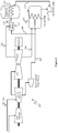
- An illustrative embodiment of a system having a fluid conditioning unit comprising a blend station in accordance with the present invention is shown in Figure 3 .
- a high pressure steam 201 enters a power generator 203 comprising high, intermediate, low pressure, and boiler feedwater pump turbines.
- Low pressure steams 206 and 207 are produced by the power generator 203, from the low pressure and boiler feedwater turbine portions.
- a portion of the low pressure steam 209 is diverted to a blend station 213.
- the portion of the low pressure steam 209 comprises low pressure steams 206 and 207 from the low pressure turbine and the boiler feedwater pump turbine, respectively.
- the low pressure steam 206 and 207 could be combined prior to diverting a portion of the low pressure steam 209 to the blend station 213.
- the blend station 213 mixes the portion of the low pressure steam 209 with a second stream 211 having a pressure greater than that of the portion of the low pressure steam 209.
- the second stream 211 is preferably a product of a low pressure turbine, although it is contemplated that the second stream 211 could be generated using any commercially suitable process. It is further contemplated that the second stream 211 can comprise a reheated steam or a product from a supplemental or auxiliary source. If superheated steam is used, then desuperheating can be used to saturate the stream.
- the blending of the second stream 211 and the portion of the low pressure steam 209 produces a conditioned stream 215, preferably at a temperature and pressure sufficient to allow for generation of a lean solvent from a CO 2 rich solvent in reboiler 217.
- the conditioned stream 215 is condensed 219 and fed to condensate pump 223, which can send the condensate back to the cycle.
- the fluid conditioning unit 210 comprises a compressor 225, such as shown in Figure 4 .
- a high pressure steam is fed into a power generator that produces a low pressure steam.
- a compressor 225 is used to compress a portion of the low pressure steam 209.
- the compressor 225 can be a steam or electrical driven compressor, a blower, a fan, or other device suitable to pressurize the portion of the low pressure steam 209 and provide the conditions necessary for the reboiler 217 in the conditioned stream 215.
- a compressor 225 fluidly coupled to a heat exchanger 227 can be used to condition low pressure steam from the power generator 203.
- the heat exchanger 227 can advantageously be used to supply additional thermal energy to compressed stream 226.
- the heat exchanger can be configured to allow for heat exchange contact between compressed stream 226 and a heated stream from an upstream process.
- the heated stream can comprise a flue gas stream.
- FGD flue gas desulfurization
- the flue gas temperature is typically about 126.7°C - 160°C (260-320 °F) depending upon the fuel and design.
- use of the flue gas as a heat exchange medium may require that the heat exchanger be made from corrosion resistant materials due to the presence of acid gases in the flue gas, such as SO 3 , SO 2 , and HCl.
- the compressor 225 can be coupled to an auxiliary heater 229 wherein the auxiliary heater receives the compressed stream 226 and produces the conditioned stream 215 as shown in Figure 6 .
- the auxiliary heater 229 preferably comprises utilizing heat from an external source or heat from at least one of an airheater, an outlet of a fabric filter or an electrostatic precipitator, or inlet stream of a FGD unit.
- Another example can comprise of the conditioning unit 210 including a blend station 213 that is configured to receive a compressed stream 226 from the compressor 225 and a second stream 211 wherein a conditioned stream is produced as shown in Figure 7 .
- the methods according to claims 6 and 8 include the steps of: (1) producing a low pressure steam in a power generator 301; (2) conditioning at least a portion of the low pressure steam in a fluid conditioning unit to produce a conditioned stream 303; and (3) heating a CO 2 rich solvent using the conditioned stream to produce a lean solvent 305.
- energy production of the power generator is increased by extracting pressure from the intermediate pressure stream rather than feed the intermediate pressure steam to the reboiler.
- the amount of power required for CO 2 sequestration is reduced.
- the efficiency is improved and the costs are reduced.
- the conditioning of a portion of the low pressure steam 303 can comprise of a plurality of steps.
- the conditioning can comprise of mixing a portion of the low pressure steam with a second stream 309 using a blend station.
- a step of producing the second stream 307 can comprise of using a low pressure turbine, a feedwater heater, and a superheater steam generator.
- the conditioning of a portion of low pressure steam 303 can comprise of a compressor to compress the portion 311.
- a compressed stream produced by the compressor can be either heated 313 and/or mixed with another stream 315.
- such methods can be configured in a manner such that the mere compressing of the portion of the low pressure stream produces a conditioned stream.
- the methods provided can reduce the duty of a condenser 317 downstream from the power generator.
- a flue gas stream typically upstream from a flue gas conditioning unit, can exchange heat with a compressed stream from a compressor, such that a conditioning stream is produced.
- systems and methods described above can be applied in operations other than power generation and CO 2 capture.
- the systems and methods can be applied to fossil fuel fired plants that have a condenser and carbon dioxide capture, including those fired with coal, gas, oil, coke, diesel, oil-derived fuels, bitumen, etc.
- applications with biomass firing, waste to energy, biodiesel, and ethanol can be modified to better benefit in energy management using the techniques described above.
- Coupled to is intended to include both direct coupling (in which two elements that are coupled to each other contact each other) and indirect coupling (in which at least one additional element is located between the two elements). Therefore, the terms “coupled to” and “coupled with” are used synonymously.
Landscapes
- Engineering & Computer Science (AREA)
- Chemical & Material Sciences (AREA)
- Chemical Kinetics & Catalysis (AREA)
- Analytical Chemistry (AREA)
- General Chemical & Material Sciences (AREA)
- Oil, Petroleum & Natural Gas (AREA)
- Combustion & Propulsion (AREA)
- Mechanical Engineering (AREA)
- General Engineering & Computer Science (AREA)
- Treating Waste Gases (AREA)
- Gas Separation By Absorption (AREA)
- Carbon And Carbon Compounds (AREA)
Claims (10)
- Système qui régénère un solvant pauvre à partir d'un solvant riche en CO2, comprenant :un générateur de puissance (203) comprenant une turbine à haute pression, une turbine à pression intermédiaire et une turbine à basse pression ; dans lequel le générateur de puissance (203) est configurépour recevoir une vapeur à haute pression (201) dans la turbine à haute pression et dans la turbine à pression intermédiaire,pour produire une première vapeur à pression intermédiaire et une seconde vapeur à pression intermédiaire de la turbine à pression intermédiaire, etpour produire une première vapeur à basse pression (206) de la turbine à basse pression, dans lequel la turbine à basse pression reçoit la première vapeur à pression intermédiaire ;une turbine de pompe d'eau d'alimentation de chaudière configurée pour produire une seconde vapeur à basse pression (207) à partir de la seconde vapeur à pression intermédiaire ;une unité de conditionnement de fluide configurée pour recevoir une première partie de la seconde vapeur à basse pression (207) et une première partie de la première vapeur à basse pression (206) et pour produire un flux conditionné (215) ;un condenseur (221) configuré pour recevoir une seconde partie de la seconde vapeur à basse pression (207) et une seconde partie de la première vapeur à basse pression (206), et pour produire un condensat ; etun échangeur de chaleur (217) configuré pour (a) recevoir le flux conditionné (215) et un solvant riche en CO2, et pour (b) produire un solvant pauvre à partir du solvant riche en CO2 en utilisant le flux conditionné (215),dans lequel l'unité de conditionnement de fluide comprend une station de mélange (213) configurée pour mélanger au moins la première partie de la seconde vapeur à basse pression (207) et la première partie de la première vapeur à basse pression (206) avec un second flux (211) ayant une pression qui est supérieure à la première et à la seconde vapeur à basse pression (206, 207) mais inférieure à la vapeur à haute pression (201), dans laquelle le second flux (211) comprend un produit d'un au moins d'une de turbine à basse pression, un réchauffeur d'eau d'alimentation, et un générateur de vapeur surchauffée ;dans lequel en outre le condensat est reçu du condenseur (221) et pompé par une pompe à condensat (223), et dans lequel un flux conditionné condensé (219) est reçu de l'échangeur de chaleur (217) et pompé par la pompe à condensat (223).
- Système qui régénère un solvant pauvre à partir d'un solvant riche en CO2, comprenant :un générateur de puissance (203) comprenant une turbine à haute pression, une turbine à pression intermédiaire et une turbine à basse pression ; dans lequel le générateur de puissance (203) est configurépour recevoir une vapeur à haute pression (201) dans la turbine à haute pression et dans la turbine à pression intermédiaire,pour produire une première vapeur à pression intermédiaire et une seconde vapeur à pression intermédiaire de la turbine à pression intermédiaire, etpour produire une première vapeur à basse pression (206) de la turbine à basse pression, dans lequel la turbine à basse pression reçoit la première vapeur à pression intermédiaire ;une turbine de pompe d'eau d'alimentation de chaudière configurée pour produire une seconde vapeur à basse pression (207) à partir de la seconde vapeur à pression intermédiaire ;une unité de conditionnement de fluide configurée pour recevoir une première partie de la seconde vapeur à basse pression (207) et une première partie de la première vapeur à basse pression (206) et pour produire un flux conditionné (215) ;un condenseur (221) configuré pour recevoir une seconde partie de la seconde vapeur à basse pression (207) et une seconde partie de la première vapeur à basse pression (206), et pour produire un condensat ; etun échangeur de chaleur (217) configuré pour (a) recevoir le flux conditionné (215) et un solvant riche en CO2, et pour (b) produire un solvant pauvre à partir d'un solvant riche en CO2 en utilisant le flux conditionné (215) ;dans lequel l'unité de conditionnement de fluide comprend un compresseur (225) configuré pour recevoir la première partie de la seconde vapeur à basse pression (207) et la première partie de la première vapeur à basse pression (206) ;dans lequel en outre le condensat est reçu du condenseur (221) et pompé par une pompe à condensat (223), et dans lequel un flux conditionné condensé (219) est reçu de l'échangeur de chaleur (217) et pompé par la pompe à condensat (223).
- Système selon la revendication 2, dans lequel l'unité de conditionnement de fluide comprend en outre un échangeur de chaleur (227) configuré pour recevoir un flux comprimé (226) du compresseur (225) et pour produire le flux conditionné (215) par contact d'échange de chaleur,
de préférence dans lequel le flux conditionné (215) est produit par contact d'échange de chaleur avec un flux de gaz de combustion. - Système de la revendication 2, dans lequel l'unité de conditionnement de fluide comprend en outre un rechauffeur auxiliaire (229) configuré pour recevoir un flux comprimé (226) du compresseur (227) et pour produire le flux conditionné (215).
- Système de la revendication 2, dans lequel l'unité de conditionnement de fluide comprend en outre une station de mélange (213) configurée pour (a) recevoir un flux comprimé (226) du compresseur (227) et un second flux (211), et (b) pour produire le flux conditionné (215).
- Méthode pour régénérer un solvant pauvre à partir d'un solvant riche en CO2, comprenant :la réception d'une vapeur à haute pression (201) dans une turbine à haute pression d'un générateur de puissance (203) et dans une turbine à pression intermédiaire du générateur de puissance (203) ;la production des première et seconde vapeurs à pression intermédiaire de la turbine à pression intermédiaire ;la réception de la première vapeur à pression intermédiaire dans une turbine à basse pression du générateur de puissance (203) ;la production d'une première vapeur à basse pression (206) de la turbine à basse pression ;la production d'une seconde vapeur à basse pression (207) de la seconde vapeur à pression intermédiaire en utilisant une turbine de pompe d'eau d'alimentation de chaudière ;le conditionnement d'une première partie de la seconde vapeur à basse pression (207) et d'une première partie de la première vapeur à basse pression (206) dans une unité de conditionnement de fluide pour produire un flux conditionné (215) ;la condensation d'une seconde partie de la seconde vapeur à basse pression (207) et d'une seconde partie de la première vapeur à basse pression (206) dans un condenseur (221) pour produire un condensat ; etle chauffage d'un solvant riche en CO2 en utilisant le flux conditionné (215) dans un échangeur de chaleur (217) pour produire un solvant pauvre ;dans lequel le conditionnement de la première partie de la seconde vapeur à basse pression (207) et de la première partie de la première vapeur à basse pression (206) comprend en outre le mélange de la première partie de la seconde vapeur à basse pression (207) et de la première partie de la première vapeur à basse pression (206) avec un second flux (211) en utilisant une station de mélange (213), dans laquelle le second flux (211) a une pression qui est supérieure à une pression de la première et de la seconde vapeur à basse pression (206, 207) ;dans lequel en outre le condensat est reçu du condenseur (221) et pompé par une pompe à condensat (223), et dans lequel un flux conditionné condensé (219) est reçu de l'échangeur de chaleur (217) et pompé par la pompe à condensat (223).
- Méthode de la revendication 6, comprenant en outre une étape de production du second flux (211) en utilisant l'un au moins d'une turbine à basse pression, un rechauffeur d'eau d'alimentation et un générateur de vapeur surchauffée.
- Méthode pour régénérer un solvant pauvre à partir du solvant riche en CO2, comprenant :la réception d'une vapeur à haute pression (201) dans une turbine à haute pression d'un générateur de puissance (203) et dans une turbine à pression intermédiaire du générateur de puissance (203) ;la production des première et seconde vapeurs à pression intermédiaire de la turbine à pression intermédiaire ;la réception de la première vapeur à pression intermédiaire dans une turbine à basse pression du générateur de puissance (203) ;la production d'une première vapeur à basse pression (206) de la turbine à basse pression ;la production d'une seconde vapeur à basse pression (207) de la seconde vapeur à pression intermédiaire en utilisant une turbine de pompe d'eau d'alimentation de chaudière ;le conditionnement d'une première partie de la seconde vapeur à basse pression (207) et d'une première partie de la première vapeur à basse pression (206) dans une unité de conditionnement de fluide pour produire un flux conditionné (215) ;la condensation d'une seconde partie de la seconde vapeur à basse pression (207) et d'une seconde partie de la première vapeur à basse pression (206) dans un condenseur (221) pour produire un condensat ; etle chauffage d'un solvant riche en CO2 en utilisant le flux conditionné (215) dans un échangeur de chaleur (217) pour produire un solvant pauvre ;dans laquelle l'unité de conditionnement de fluide comprend un compresseur (225) configuré pour recevoir la première partie de la seconde vapeur à basse pression (207) et la première partie de la première vapeur à basse pression (206) et pour produire un flux comprimé ;dans laquelle en outre le condensat est reçu du condenseur (221) et pompé par une pompe à condensat (223), et dans laquelle un flux conditionné condensé (219) est reçu de l'échangeur de chaleur (217) et pompé par la pompe à condensat (223).
- Méthode de la revendication 8, dans laquelle le flux comprimé est le flux conditionné (215), ou dans laquelle l'étape de conditionnement de la première partie de la seconde vapeur à basse pression (207) et de la première partie de la première vapeur à basse pression (206) comprend en outre :le chauffage du flux comprimé produit par le compresseur (225) par contact d'échange de chaleur avec un flux de gaz de combustion en amont d'une unité de conditionnement de gaz de combustion pour produire le flux conditionné (215), oule chauffage d'un flux comprimé (226) par le compresseur (225) en utilisant un rechauffeur auxiliaire (229) pour produire le flux conditionné (215), oule mélange d'un flux comprimé (226) par le compresseur (225) et d'un second flux (211) pour produire le flux conditionné (215), et dans laquelle le second flux (211) a une pression qui est supérieure à une pression de la première et de la seconde vapeur à basse pression (206, 207).
- Méthode de la revendication 6 ou 8, comprenant en outre la réduction d'une charge du condenseur (221).
Applications Claiming Priority (1)
| Application Number | Priority Date | Filing Date | Title |
|---|---|---|---|
| PCT/US2012/048394 WO2014018046A1 (fr) | 2012-07-26 | 2012-07-26 | Rendement de vapeur avec condensation non déplétive et échauffement adiabatique de solvent |
Publications (3)
| Publication Number | Publication Date |
|---|---|
| EP2877258A1 EP2877258A1 (fr) | 2015-06-03 |
| EP2877258A4 EP2877258A4 (fr) | 2016-03-16 |
| EP2877258B1 true EP2877258B1 (fr) | 2018-10-24 |
Family
ID=49997677
Family Applications (1)
| Application Number | Title | Priority Date | Filing Date |
|---|---|---|---|
| EP12881733.5A Not-in-force EP2877258B1 (fr) | 2012-07-26 | 2012-07-26 | Rendement de vapeur avec condensation non déplétive et échauffement adiabatique de solvent |
Country Status (5)
| Country | Link |
|---|---|
| EP (1) | EP2877258B1 (fr) |
| JP (1) | JP6138255B2 (fr) |
| AU (1) | AU2012386010B2 (fr) |
| CA (1) | CA2880187A1 (fr) |
| WO (1) | WO2014018046A1 (fr) |
Families Citing this family (1)
| Publication number | Priority date | Publication date | Assignee | Title |
|---|---|---|---|---|
| WO2018189947A1 (fr) * | 2017-04-13 | 2018-10-18 | 関西電力株式会社 | Système et procédé de récupération de dioxyde de carbone |
Citations (1)
| Publication number | Priority date | Publication date | Assignee | Title |
|---|---|---|---|---|
| EP2333256A1 (fr) * | 2009-12-08 | 2011-06-15 | Alstom Technology Ltd | Centrale électrique dotée de capture de CO2 et son procédé d'opération |
Family Cites Families (13)
| Publication number | Priority date | Publication date | Assignee | Title |
|---|---|---|---|---|
| US4160810A (en) * | 1978-03-07 | 1979-07-10 | Benfield Corporation | Removal of acid gases from hot gas mixtures |
| JP2792777B2 (ja) * | 1992-01-17 | 1998-09-03 | 関西電力株式会社 | 燃焼排ガス中の炭酸ガスの除去方法 |
| JP4274846B2 (ja) * | 2003-04-30 | 2009-06-10 | 三菱重工業株式会社 | 二酸化炭素の回収方法及びそのシステム |
| JP4875303B2 (ja) * | 2005-02-07 | 2012-02-15 | 三菱重工業株式会社 | 二酸化炭素回収システム、これを用いた発電システムおよびこれら方法 |
| WO2007133595A2 (fr) | 2006-05-08 | 2007-11-22 | The Board Of Trustees Of The University Of Illinois | Séparation de gaz par cycle vapeur à absorption sous vide intégrée |
| US20090151318A1 (en) * | 2007-12-13 | 2009-06-18 | Alstom Technology Ltd | System and method for regenerating an absorbent solution |
| JP5558036B2 (ja) * | 2008-09-04 | 2014-07-23 | 株式会社東芝 | 二酸化炭素回収型汽力発電システム |
| US20100205964A1 (en) * | 2009-02-13 | 2010-08-19 | General Electric Company | Post-combustion processing in power plants |
| JP5484811B2 (ja) * | 2009-07-17 | 2014-05-07 | 三菱重工業株式会社 | 二酸化炭素の回収システム及び方法 |
| CA2722195C (fr) * | 2009-11-25 | 2013-03-19 | Hitachi, Ltd. | Centrale thermique a combustion de combustible fossile comprenant une unite de separation et de capture du dioxyde de carbone |
| JP5558310B2 (ja) * | 2010-10-22 | 2014-07-23 | 株式会社東芝 | 二酸化炭素回収方法及び二酸化炭素回収型汽力発電システム |
| JP5812694B2 (ja) * | 2011-05-31 | 2015-11-17 | 川崎重工業株式会社 | 二酸化炭素回収方法および装置 |
| JP5734883B2 (ja) * | 2012-01-24 | 2015-06-17 | 株式会社東芝 | 二酸化炭素分離回収装置、二酸化炭素回収型汽力発電システム、及び二酸化炭素回収型汽力発電システムの運転方法 |
-
2012
- 2012-07-26 EP EP12881733.5A patent/EP2877258B1/fr not_active Not-in-force
- 2012-07-26 JP JP2015524231A patent/JP6138255B2/ja not_active Expired - Fee Related
- 2012-07-26 WO PCT/US2012/048394 patent/WO2014018046A1/fr not_active Ceased
- 2012-07-26 CA CA2880187A patent/CA2880187A1/fr not_active Abandoned
- 2012-07-26 AU AU2012386010A patent/AU2012386010B2/en not_active Ceased
Patent Citations (1)
| Publication number | Priority date | Publication date | Assignee | Title |
|---|---|---|---|---|
| EP2333256A1 (fr) * | 2009-12-08 | 2011-06-15 | Alstom Technology Ltd | Centrale électrique dotée de capture de CO2 et son procédé d'opération |
Also Published As
| Publication number | Publication date |
|---|---|
| JP6138255B2 (ja) | 2017-05-31 |
| AU2012386010B2 (en) | 2018-02-15 |
| EP2877258A1 (fr) | 2015-06-03 |
| CA2880187A1 (fr) | 2014-01-30 |
| JP2015530917A (ja) | 2015-10-29 |
| EP2877258A4 (fr) | 2016-03-16 |
| AU2012386010A1 (en) | 2015-02-19 |
| WO2014018046A1 (fr) | 2014-01-30 |
Similar Documents
| Publication | Publication Date | Title |
|---|---|---|
| US7827778B2 (en) | Power plants that utilize gas turbines for power generation and processes for lowering CO2 emissions | |
| CN101187338B (zh) | 具有二氧化碳隔离的发电系统和方法 | |
| US8007570B2 (en) | Systems, methods, and apparatus for capturing CO2 using a solvent | |
| US10006634B2 (en) | Coal fired oxy plant with air separation unit including parallel coupled heat exchanger | |
| US9915424B2 (en) | Coal fired Oxy plant with Flue Gas Heat Recovery | |
| US20140020388A1 (en) | System for improved carbon dioxide capture and method thereof | |
| JP7412102B2 (ja) | ガスタービンプラント | |
| CN103228890A (zh) | 带有co2捕集的联合循环动力设备和操作其的方法 | |
| US9157369B2 (en) | Waste heat utilization for energy efficient carbon capture | |
| AU2013313605B2 (en) | Heat recovery system and heat recovery method | |
| US9108123B2 (en) | Steam efficiency with non depletive condensing and adiabatic solvent heating | |
| EP2108888A1 (fr) | Installation de capture de carbone et système de centrale électrique | |
| EP2634482A2 (fr) | Procédé de production d'électricité et système de capture post-combustion | |
| US20140109575A1 (en) | Method for reducing flue gas carbon dioxide emissions | |
| AU2012386010B2 (en) | Steam efficiency with non depletive condensing and adiabatic solvent heating | |
| US20120159924A1 (en) | System and method for increasing efficiency and water recovery of a combined cycle power plant | |
| CN105163831B (zh) | 用于降低二氧化碳捕获装置的能量需求的系统和方法 | |
| CN105863757A (zh) | 一种发电系统的电网负荷运行方法 | |
| RU2837807C2 (ru) | Система генерации электроэнергии, включающая в себя газовую турбину с теплоутилизационным парогенератором и улавливанием диоксида углерода, и способ | |
| US10378763B2 (en) | Method and apparatus to facilitate heating feedwater in a power generation system | |
| RU2561354C2 (ru) | Способ работы газопаровой установки | |
| WO2014065778A1 (fr) | Procédé pour réduire les émissions de dioxyde de carbone d'un gaz de cheminée | |
| CN105736079A (zh) | 发电系统电网运行控制方法 | |
| HK1158289A1 (en) | Thermal power plant with co2 sequestration | |
| HK1158289B (en) | Thermal power plant with co2 sequestration |
Legal Events
| Date | Code | Title | Description |
|---|---|---|---|
| PUAI | Public reference made under article 153(3) epc to a published international application that has entered the european phase |
Free format text: ORIGINAL CODE: 0009012 |
|
| 17P | Request for examination filed |
Effective date: 20150225 |
|
| AK | Designated contracting states |
Kind code of ref document: A1 Designated state(s): AL AT BE BG CH CY CZ DE DK EE ES FI FR GB GR HR HU IE IS IT LI LT LU LV MC MK MT NL NO PL PT RO RS SE SI SK SM TR |
|
| AX | Request for extension of the european patent |
Extension state: BA ME |
|
| DAX | Request for extension of the european patent (deleted) | ||
| RA4 | Supplementary search report drawn up and despatched (corrected) |
Effective date: 20160212 |
|
| RIC1 | Information provided on ipc code assigned before grant |
Ipc: B01D 53/14 20060101ALI20160208BHEP Ipc: F01K 17/00 20060101ALI20160208BHEP Ipc: F23J 15/00 20060101ALI20160208BHEP Ipc: B01D 5/00 20060101AFI20160208BHEP |
|
| STAA | Information on the status of an ep patent application or granted ep patent |
Free format text: STATUS: EXAMINATION IS IN PROGRESS |
|
| 17Q | First examination report despatched |
Effective date: 20170323 |
|
| GRAP | Despatch of communication of intention to grant a patent |
Free format text: ORIGINAL CODE: EPIDOSNIGR1 |
|
| STAA | Information on the status of an ep patent application or granted ep patent |
Free format text: STATUS: GRANT OF PATENT IS INTENDED |
|
| INTG | Intention to grant announced |
Effective date: 20180507 |
|
| GRAS | Grant fee paid |
Free format text: ORIGINAL CODE: EPIDOSNIGR3 |
|
| GRAA | (expected) grant |
Free format text: ORIGINAL CODE: 0009210 |
|
| STAA | Information on the status of an ep patent application or granted ep patent |
Free format text: STATUS: THE PATENT HAS BEEN GRANTED |
|
| AK | Designated contracting states |
Kind code of ref document: B1 Designated state(s): AL AT BE BG CH CY CZ DE DK EE ES FI FR GB GR HR HU IE IS IT LI LT LU LV MC MK MT NL NO PL PT RO RS SE SI SK SM TR |
|
| REG | Reference to a national code |
Ref country code: CH Ref legal event code: EP |
|
| REG | Reference to a national code |
Ref country code: IE Ref legal event code: FG4D |
|
| REG | Reference to a national code |
Ref country code: DE Ref legal event code: R096 Ref document number: 602012052756 Country of ref document: DE Ref country code: AT Ref legal event code: REF Ref document number: 1056019 Country of ref document: AT Kind code of ref document: T Effective date: 20181115 |
|
| REG | Reference to a national code |
Ref country code: NL Ref legal event code: MP Effective date: 20181024 |
|
| REG | Reference to a national code |
Ref country code: LT Ref legal event code: MG4D |
|
| REG | Reference to a national code |
Ref country code: AT Ref legal event code: MK05 Ref document number: 1056019 Country of ref document: AT Kind code of ref document: T Effective date: 20181024 |
|
| PG25 | Lapsed in a contracting state [announced via postgrant information from national office to epo] |
Ref country code: NL Free format text: LAPSE BECAUSE OF FAILURE TO SUBMIT A TRANSLATION OF THE DESCRIPTION OR TO PAY THE FEE WITHIN THE PRESCRIBED TIME-LIMIT Effective date: 20181024 |
|
| PG25 | Lapsed in a contracting state [announced via postgrant information from national office to epo] |
Ref country code: ES Free format text: LAPSE BECAUSE OF FAILURE TO SUBMIT A TRANSLATION OF THE DESCRIPTION OR TO PAY THE FEE WITHIN THE PRESCRIBED TIME-LIMIT Effective date: 20181024 Ref country code: LV Free format text: LAPSE BECAUSE OF FAILURE TO SUBMIT A TRANSLATION OF THE DESCRIPTION OR TO PAY THE FEE WITHIN THE PRESCRIBED TIME-LIMIT Effective date: 20181024 Ref country code: AT Free format text: LAPSE BECAUSE OF FAILURE TO SUBMIT A TRANSLATION OF THE DESCRIPTION OR TO PAY THE FEE WITHIN THE PRESCRIBED TIME-LIMIT Effective date: 20181024 Ref country code: PL Free format text: LAPSE BECAUSE OF FAILURE TO SUBMIT A TRANSLATION OF THE DESCRIPTION OR TO PAY THE FEE WITHIN THE PRESCRIBED TIME-LIMIT Effective date: 20181024 Ref country code: NO Free format text: LAPSE BECAUSE OF FAILURE TO SUBMIT A TRANSLATION OF THE DESCRIPTION OR TO PAY THE FEE WITHIN THE PRESCRIBED TIME-LIMIT Effective date: 20190124 Ref country code: LT Free format text: LAPSE BECAUSE OF FAILURE TO SUBMIT A TRANSLATION OF THE DESCRIPTION OR TO PAY THE FEE WITHIN THE PRESCRIBED TIME-LIMIT Effective date: 20181024 Ref country code: FI Free format text: LAPSE BECAUSE OF FAILURE TO SUBMIT A TRANSLATION OF THE DESCRIPTION OR TO PAY THE FEE WITHIN THE PRESCRIBED TIME-LIMIT Effective date: 20181024 Ref country code: IS Free format text: LAPSE BECAUSE OF FAILURE TO SUBMIT A TRANSLATION OF THE DESCRIPTION OR TO PAY THE FEE WITHIN THE PRESCRIBED TIME-LIMIT Effective date: 20190224 Ref country code: BG Free format text: LAPSE BECAUSE OF FAILURE TO SUBMIT A TRANSLATION OF THE DESCRIPTION OR TO PAY THE FEE WITHIN THE PRESCRIBED TIME-LIMIT Effective date: 20190124 Ref country code: HR Free format text: LAPSE BECAUSE OF FAILURE TO SUBMIT A TRANSLATION OF THE DESCRIPTION OR TO PAY THE FEE WITHIN THE PRESCRIBED TIME-LIMIT Effective date: 20181024 |
|
| PG25 | Lapsed in a contracting state [announced via postgrant information from national office to epo] |
Ref country code: RS Free format text: LAPSE BECAUSE OF FAILURE TO SUBMIT A TRANSLATION OF THE DESCRIPTION OR TO PAY THE FEE WITHIN THE PRESCRIBED TIME-LIMIT Effective date: 20181024 Ref country code: GR Free format text: LAPSE BECAUSE OF FAILURE TO SUBMIT A TRANSLATION OF THE DESCRIPTION OR TO PAY THE FEE WITHIN THE PRESCRIBED TIME-LIMIT Effective date: 20190125 Ref country code: SE Free format text: LAPSE BECAUSE OF FAILURE TO SUBMIT A TRANSLATION OF THE DESCRIPTION OR TO PAY THE FEE WITHIN THE PRESCRIBED TIME-LIMIT Effective date: 20181024 Ref country code: AL Free format text: LAPSE BECAUSE OF FAILURE TO SUBMIT A TRANSLATION OF THE DESCRIPTION OR TO PAY THE FEE WITHIN THE PRESCRIBED TIME-LIMIT Effective date: 20181024 Ref country code: PT Free format text: LAPSE BECAUSE OF FAILURE TO SUBMIT A TRANSLATION OF THE DESCRIPTION OR TO PAY THE FEE WITHIN THE PRESCRIBED TIME-LIMIT Effective date: 20190224 |
|
| REG | Reference to a national code |
Ref country code: DE Ref legal event code: R097 Ref document number: 602012052756 Country of ref document: DE |
|
| PG25 | Lapsed in a contracting state [announced via postgrant information from national office to epo] |
Ref country code: DK Free format text: LAPSE BECAUSE OF FAILURE TO SUBMIT A TRANSLATION OF THE DESCRIPTION OR TO PAY THE FEE WITHIN THE PRESCRIBED TIME-LIMIT Effective date: 20181024 Ref country code: IT Free format text: LAPSE BECAUSE OF FAILURE TO SUBMIT A TRANSLATION OF THE DESCRIPTION OR TO PAY THE FEE WITHIN THE PRESCRIBED TIME-LIMIT Effective date: 20181024 Ref country code: CZ Free format text: LAPSE BECAUSE OF FAILURE TO SUBMIT A TRANSLATION OF THE DESCRIPTION OR TO PAY THE FEE WITHIN THE PRESCRIBED TIME-LIMIT Effective date: 20181024 |
|
| PG25 | Lapsed in a contracting state [announced via postgrant information from national office to epo] |
Ref country code: SK Free format text: LAPSE BECAUSE OF FAILURE TO SUBMIT A TRANSLATION OF THE DESCRIPTION OR TO PAY THE FEE WITHIN THE PRESCRIBED TIME-LIMIT Effective date: 20181024 Ref country code: RO Free format text: LAPSE BECAUSE OF FAILURE TO SUBMIT A TRANSLATION OF THE DESCRIPTION OR TO PAY THE FEE WITHIN THE PRESCRIBED TIME-LIMIT Effective date: 20181024 Ref country code: SM Free format text: LAPSE BECAUSE OF FAILURE TO SUBMIT A TRANSLATION OF THE DESCRIPTION OR TO PAY THE FEE WITHIN THE PRESCRIBED TIME-LIMIT Effective date: 20181024 Ref country code: EE Free format text: LAPSE BECAUSE OF FAILURE TO SUBMIT A TRANSLATION OF THE DESCRIPTION OR TO PAY THE FEE WITHIN THE PRESCRIBED TIME-LIMIT Effective date: 20181024 |
|
| PLBE | No opposition filed within time limit |
Free format text: ORIGINAL CODE: 0009261 |
|
| STAA | Information on the status of an ep patent application or granted ep patent |
Free format text: STATUS: NO OPPOSITION FILED WITHIN TIME LIMIT |
|
| 26N | No opposition filed |
Effective date: 20190725 |
|
| PG25 | Lapsed in a contracting state [announced via postgrant information from national office to epo] |
Ref country code: SI Free format text: LAPSE BECAUSE OF FAILURE TO SUBMIT A TRANSLATION OF THE DESCRIPTION OR TO PAY THE FEE WITHIN THE PRESCRIBED TIME-LIMIT Effective date: 20181024 |
|
| REG | Reference to a national code |
Ref country code: DE Ref legal event code: R119 Ref document number: 602012052756 Country of ref document: DE |
|
| PG25 | Lapsed in a contracting state [announced via postgrant information from national office to epo] |
Ref country code: MC Free format text: LAPSE BECAUSE OF FAILURE TO SUBMIT A TRANSLATION OF THE DESCRIPTION OR TO PAY THE FEE WITHIN THE PRESCRIBED TIME-LIMIT Effective date: 20181024 |
|
| REG | Reference to a national code |
Ref country code: CH Ref legal event code: PL |
|
| GBPC | Gb: european patent ceased through non-payment of renewal fee |
Effective date: 20190726 |
|
| PG25 | Lapsed in a contracting state [announced via postgrant information from national office to epo] |
Ref country code: TR Free format text: LAPSE BECAUSE OF FAILURE TO SUBMIT A TRANSLATION OF THE DESCRIPTION OR TO PAY THE FEE WITHIN THE PRESCRIBED TIME-LIMIT Effective date: 20181024 |
|
| REG | Reference to a national code |
Ref country code: BE Ref legal event code: MM Effective date: 20190731 |
|
| PG25 | Lapsed in a contracting state [announced via postgrant information from national office to epo] |
Ref country code: DE Free format text: LAPSE BECAUSE OF NON-PAYMENT OF DUE FEES Effective date: 20200201 Ref country code: GB Free format text: LAPSE BECAUSE OF NON-PAYMENT OF DUE FEES Effective date: 20190726 |
|
| PG25 | Lapsed in a contracting state [announced via postgrant information from national office to epo] |
Ref country code: LI Free format text: LAPSE BECAUSE OF NON-PAYMENT OF DUE FEES Effective date: 20190731 Ref country code: LU Free format text: LAPSE BECAUSE OF NON-PAYMENT OF DUE FEES Effective date: 20190726 Ref country code: CH Free format text: LAPSE BECAUSE OF NON-PAYMENT OF DUE FEES Effective date: 20190731 Ref country code: BE Free format text: LAPSE BECAUSE OF NON-PAYMENT OF DUE FEES Effective date: 20190731 |
|
| PG25 | Lapsed in a contracting state [announced via postgrant information from national office to epo] |
Ref country code: FR Free format text: LAPSE BECAUSE OF NON-PAYMENT OF DUE FEES Effective date: 20190731 |
|
| PG25 | Lapsed in a contracting state [announced via postgrant information from national office to epo] |
Ref country code: IE Free format text: LAPSE BECAUSE OF NON-PAYMENT OF DUE FEES Effective date: 20190726 |
|
| PG25 | Lapsed in a contracting state [announced via postgrant information from national office to epo] |
Ref country code: CY Free format text: LAPSE BECAUSE OF FAILURE TO SUBMIT A TRANSLATION OF THE DESCRIPTION OR TO PAY THE FEE WITHIN THE PRESCRIBED TIME-LIMIT Effective date: 20181024 |
|
| PG25 | Lapsed in a contracting state [announced via postgrant information from national office to epo] |
Ref country code: MT Free format text: LAPSE BECAUSE OF FAILURE TO SUBMIT A TRANSLATION OF THE DESCRIPTION OR TO PAY THE FEE WITHIN THE PRESCRIBED TIME-LIMIT Effective date: 20181024 Ref country code: HU Free format text: LAPSE BECAUSE OF FAILURE TO SUBMIT A TRANSLATION OF THE DESCRIPTION OR TO PAY THE FEE WITHIN THE PRESCRIBED TIME-LIMIT; INVALID AB INITIO Effective date: 20120726 |
|
| PG25 | Lapsed in a contracting state [announced via postgrant information from national office to epo] |
Ref country code: MK Free format text: LAPSE BECAUSE OF FAILURE TO SUBMIT A TRANSLATION OF THE DESCRIPTION OR TO PAY THE FEE WITHIN THE PRESCRIBED TIME-LIMIT Effective date: 20181024 |