EP2877362B1 - Interface de commande, procédé d'affichage d'une information facilitant l'utilisation d'une interface de commande et programme - Google Patents
Interface de commande, procédé d'affichage d'une information facilitant l'utilisation d'une interface de commande et programme Download PDFInfo
- Publication number
- EP2877362B1 EP2877362B1 EP13741717.6A EP13741717A EP2877362B1 EP 2877362 B1 EP2877362 B1 EP 2877362B1 EP 13741717 A EP13741717 A EP 13741717A EP 2877362 B1 EP2877362 B1 EP 2877362B1
- Authority
- EP
- European Patent Office
- Prior art keywords
- touch
- display
- detection area
- display element
- designed
- Prior art date
- Legal status (The legal status is an assumption and is not a legal conclusion. Google has not performed a legal analysis and makes no representation as to the accuracy of the status listed.)
- Active
Links
Images


Classifications
-
- G—PHYSICS
- G06—COMPUTING OR CALCULATING; COUNTING
- G06F—ELECTRIC DIGITAL DATA PROCESSING
- G06F3/00—Input arrangements for transferring data to be processed into a form capable of being handled by the computer; Output arrangements for transferring data from processing unit to output unit, e.g. interface arrangements
- G06F3/01—Input arrangements or combined input and output arrangements for interaction between user and computer
- G06F3/03—Arrangements for converting the position or the displacement of a member into a coded form
- G06F3/041—Digitisers, e.g. for touch screens or touch pads, characterised by the transducing means
- G06F3/0416—Control or interface arrangements specially adapted for digitisers
-
- B—PERFORMING OPERATIONS; TRANSPORTING
- B60—VEHICLES IN GENERAL
- B60K—ARRANGEMENT OR MOUNTING OF PROPULSION UNITS OR OF TRANSMISSIONS IN VEHICLES; ARRANGEMENT OR MOUNTING OF PLURAL DIVERSE PRIME-MOVERS IN VEHICLES; AUXILIARY DRIVES FOR VEHICLES; INSTRUMENTATION OR DASHBOARDS FOR VEHICLES; ARRANGEMENTS IN CONNECTION WITH COOLING, AIR INTAKE, GAS EXHAUST OR FUEL SUPPLY OF PROPULSION UNITS IN VEHICLES
- B60K35/00—Instruments specially adapted for vehicles; Arrangement of instruments in or on vehicles
-
- B—PERFORMING OPERATIONS; TRANSPORTING
- B60—VEHICLES IN GENERAL
- B60K—ARRANGEMENT OR MOUNTING OF PROPULSION UNITS OR OF TRANSMISSIONS IN VEHICLES; ARRANGEMENT OR MOUNTING OF PLURAL DIVERSE PRIME-MOVERS IN VEHICLES; AUXILIARY DRIVES FOR VEHICLES; INSTRUMENTATION OR DASHBOARDS FOR VEHICLES; ARRANGEMENTS IN CONNECTION WITH COOLING, AIR INTAKE, GAS EXHAUST OR FUEL SUPPLY OF PROPULSION UNITS IN VEHICLES
- B60K35/00—Instruments specially adapted for vehicles; Arrangement of instruments in or on vehicles
- B60K35/10—Input arrangements, i.e. from user to vehicle, associated with vehicle functions or specially adapted therefor
-
- B—PERFORMING OPERATIONS; TRANSPORTING
- B60—VEHICLES IN GENERAL
- B60K—ARRANGEMENT OR MOUNTING OF PROPULSION UNITS OR OF TRANSMISSIONS IN VEHICLES; ARRANGEMENT OR MOUNTING OF PLURAL DIVERSE PRIME-MOVERS IN VEHICLES; AUXILIARY DRIVES FOR VEHICLES; INSTRUMENTATION OR DASHBOARDS FOR VEHICLES; ARRANGEMENTS IN CONNECTION WITH COOLING, AIR INTAKE, GAS EXHAUST OR FUEL SUPPLY OF PROPULSION UNITS IN VEHICLES
- B60K35/00—Instruments specially adapted for vehicles; Arrangement of instruments in or on vehicles
- B60K35/20—Output arrangements, i.e. from vehicle to user, associated with vehicle functions or specially adapted therefor
- B60K35/21—Output arrangements, i.e. from vehicle to user, associated with vehicle functions or specially adapted therefor using visual output, e.g. blinking lights or matrix displays
- B60K35/211—Output arrangements, i.e. from vehicle to user, associated with vehicle functions or specially adapted therefor using visual output, e.g. blinking lights or matrix displays producing three-dimensional [3D] effects, e.g. stereoscopic images
-
- B—PERFORMING OPERATIONS; TRANSPORTING
- B60—VEHICLES IN GENERAL
- B60R—VEHICLES, VEHICLE FITTINGS, OR VEHICLE PARTS, NOT OTHERWISE PROVIDED FOR
- B60R16/00—Electric or fluid circuits specially adapted for vehicles and not otherwise provided for; Arrangement of elements of electric or fluid circuits specially adapted for vehicles and not otherwise provided for
- B60R16/02—Electric or fluid circuits specially adapted for vehicles and not otherwise provided for; Arrangement of elements of electric or fluid circuits specially adapted for vehicles and not otherwise provided for electric constitutive elements
-
- B—PERFORMING OPERATIONS; TRANSPORTING
- B60—VEHICLES IN GENERAL
- B60W—CONJOINT CONTROL OF VEHICLE SUB-UNITS OF DIFFERENT TYPE OR DIFFERENT FUNCTION; CONTROL SYSTEMS SPECIALLY ADAPTED FOR HYBRID VEHICLES; ROAD VEHICLE DRIVE CONTROL SYSTEMS FOR PURPOSES NOT RELATED TO THE CONTROL OF A PARTICULAR SUB-UNIT
- B60W50/00—Details of control systems for road vehicle drive control not related to the control of a particular sub-unit, e.g. process diagnostic or vehicle driver interfaces
- B60W50/08—Interaction between the driver and the control system
- B60W50/14—Means for informing the driver, warning the driver or prompting a driver intervention
-
- G—PHYSICS
- G06—COMPUTING OR CALCULATING; COUNTING
- G06F—ELECTRIC DIGITAL DATA PROCESSING
- G06F1/00—Details not covered by groups G06F3/00 - G06F13/00 and G06F21/00
- G06F1/26—Power supply means, e.g. regulation thereof
- G06F1/32—Means for saving power
- G06F1/3203—Power management, i.e. event-based initiation of a power-saving mode
- G06F1/3206—Monitoring of events, devices or parameters that trigger a change in power modality
- G06F1/3231—Monitoring the presence, absence or movement of users
-
- G—PHYSICS
- G06—COMPUTING OR CALCULATING; COUNTING
- G06F—ELECTRIC DIGITAL DATA PROCESSING
- G06F3/00—Input arrangements for transferring data to be processed into a form capable of being handled by the computer; Output arrangements for transferring data from processing unit to output unit, e.g. interface arrangements
- G06F3/01—Input arrangements or combined input and output arrangements for interaction between user and computer
- G06F3/03—Arrangements for converting the position or the displacement of a member into a coded form
- G06F3/041—Digitisers, e.g. for touch screens or touch pads, characterised by the transducing means
- G06F3/0412—Digitisers structurally integrated in a display
-
- G—PHYSICS
- G06—COMPUTING OR CALCULATING; COUNTING
- G06F—ELECTRIC DIGITAL DATA PROCESSING
- G06F3/00—Input arrangements for transferring data to be processed into a form capable of being handled by the computer; Output arrangements for transferring data from processing unit to output unit, e.g. interface arrangements
- G06F3/01—Input arrangements or combined input and output arrangements for interaction between user and computer
- G06F3/03—Arrangements for converting the position or the displacement of a member into a coded form
- G06F3/041—Digitisers, e.g. for touch screens or touch pads, characterised by the transducing means
- G06F3/0416—Control or interface arrangements specially adapted for digitisers
- G06F3/0418—Control or interface arrangements specially adapted for digitisers for error correction or compensation, e.g. based on parallax, calibration or alignment
-
- G—PHYSICS
- G06—COMPUTING OR CALCULATING; COUNTING
- G06F—ELECTRIC DIGITAL DATA PROCESSING
- G06F3/00—Input arrangements for transferring data to be processed into a form capable of being handled by the computer; Output arrangements for transferring data from processing unit to output unit, e.g. interface arrangements
- G06F3/01—Input arrangements or combined input and output arrangements for interaction between user and computer
- G06F3/048—Interaction techniques based on graphical user interfaces [GUI]
- G06F3/0484—Interaction techniques based on graphical user interfaces [GUI] for the control of specific functions or operations, e.g. selecting or manipulating an object, an image or a displayed text element, setting a parameter value or selecting a range
- G06F3/04842—Selection of displayed objects or displayed text elements
-
- G—PHYSICS
- G06—COMPUTING OR CALCULATING; COUNTING
- G06F—ELECTRIC DIGITAL DATA PROCESSING
- G06F3/00—Input arrangements for transferring data to be processed into a form capable of being handled by the computer; Output arrangements for transferring data from processing unit to output unit, e.g. interface arrangements
- G06F3/01—Input arrangements or combined input and output arrangements for interaction between user and computer
- G06F3/048—Interaction techniques based on graphical user interfaces [GUI]
- G06F3/0487—Interaction techniques based on graphical user interfaces [GUI] using specific features provided by the input device, e.g. functions controlled by the rotation of a mouse with dual sensing arrangements, or of the nature of the input device, e.g. tap gestures based on pressure sensed by a digitiser
- G06F3/0488—Interaction techniques based on graphical user interfaces [GUI] using specific features provided by the input device, e.g. functions controlled by the rotation of a mouse with dual sensing arrangements, or of the nature of the input device, e.g. tap gestures based on pressure sensed by a digitiser using a touch-screen or digitiser, e.g. input of commands through traced gestures
-
- G—PHYSICS
- G06—COMPUTING OR CALCULATING; COUNTING
- G06F—ELECTRIC DIGITAL DATA PROCESSING
- G06F3/00—Input arrangements for transferring data to be processed into a form capable of being handled by the computer; Output arrangements for transferring data from processing unit to output unit, e.g. interface arrangements
- G06F3/01—Input arrangements or combined input and output arrangements for interaction between user and computer
- G06F3/048—Interaction techniques based on graphical user interfaces [GUI]
- G06F3/0487—Interaction techniques based on graphical user interfaces [GUI] using specific features provided by the input device, e.g. functions controlled by the rotation of a mouse with dual sensing arrangements, or of the nature of the input device, e.g. tap gestures based on pressure sensed by a digitiser
- G06F3/0488—Interaction techniques based on graphical user interfaces [GUI] using specific features provided by the input device, e.g. functions controlled by the rotation of a mouse with dual sensing arrangements, or of the nature of the input device, e.g. tap gestures based on pressure sensed by a digitiser using a touch-screen or digitiser, e.g. input of commands through traced gestures
- G06F3/04883—Interaction techniques based on graphical user interfaces [GUI] using specific features provided by the input device, e.g. functions controlled by the rotation of a mouse with dual sensing arrangements, or of the nature of the input device, e.g. tap gestures based on pressure sensed by a digitiser using a touch-screen or digitiser, e.g. input of commands through traced gestures for inputting data by handwriting, e.g. gesture or text
-
- B—PERFORMING OPERATIONS; TRANSPORTING
- B60—VEHICLES IN GENERAL
- B60K—ARRANGEMENT OR MOUNTING OF PROPULSION UNITS OR OF TRANSMISSIONS IN VEHICLES; ARRANGEMENT OR MOUNTING OF PLURAL DIVERSE PRIME-MOVERS IN VEHICLES; AUXILIARY DRIVES FOR VEHICLES; INSTRUMENTATION OR DASHBOARDS FOR VEHICLES; ARRANGEMENTS IN CONNECTION WITH COOLING, AIR INTAKE, GAS EXHAUST OR FUEL SUPPLY OF PROPULSION UNITS IN VEHICLES
- B60K2360/00—Indexing scheme associated with groups B60K35/00 or B60K37/00 relating to details of instruments or dashboards
- B60K2360/141—Activation of instrument input devices by approaching fingers or pens
-
- B—PERFORMING OPERATIONS; TRANSPORTING
- B60—VEHICLES IN GENERAL
- B60K—ARRANGEMENT OR MOUNTING OF PROPULSION UNITS OR OF TRANSMISSIONS IN VEHICLES; ARRANGEMENT OR MOUNTING OF PLURAL DIVERSE PRIME-MOVERS IN VEHICLES; AUXILIARY DRIVES FOR VEHICLES; INSTRUMENTATION OR DASHBOARDS FOR VEHICLES; ARRANGEMENTS IN CONNECTION WITH COOLING, AIR INTAKE, GAS EXHAUST OR FUEL SUPPLY OF PROPULSION UNITS IN VEHICLES
- B60K2360/00—Indexing scheme associated with groups B60K35/00 or B60K37/00 relating to details of instruments or dashboards
- B60K2360/143—Touch sensitive instrument input devices
- B60K2360/1438—Touch screens
- B60K2360/1442—Emulation of input devices
-
- B—PERFORMING OPERATIONS; TRANSPORTING
- B60—VEHICLES IN GENERAL
- B60W—CONJOINT CONTROL OF VEHICLE SUB-UNITS OF DIFFERENT TYPE OR DIFFERENT FUNCTION; CONTROL SYSTEMS SPECIALLY ADAPTED FOR HYBRID VEHICLES; ROAD VEHICLE DRIVE CONTROL SYSTEMS FOR PURPOSES NOT RELATED TO THE CONTROL OF A PARTICULAR SUB-UNIT
- B60W50/00—Details of control systems for road vehicle drive control not related to the control of a particular sub-unit, e.g. process diagnostic or vehicle driver interfaces
- B60W50/08—Interaction between the driver and the control system
- B60W50/14—Means for informing the driver, warning the driver or prompting a driver intervention
- B60W2050/146—Display means
-
- G—PHYSICS
- G06—COMPUTING OR CALCULATING; COUNTING
- G06F—ELECTRIC DIGITAL DATA PROCESSING
- G06F2203/00—Indexing scheme relating to G06F3/00 - G06F3/048
- G06F2203/041—Indexing scheme relating to G06F3/041 - G06F3/045
- G06F2203/04101—2.5D-digitiser, i.e. digitiser detecting the X/Y position of the input means, finger or stylus, also when it does not touch, but is proximate to the digitiser's interaction surface and also measures the distance of the input means within a short range in the Z direction, possibly with a separate measurement setup
Definitions
- the invention relates to an operator interface, a method for displaying information that simplifies operation of an operator interface, and a program with a program code for performing such a method. These can be used, for example, to operate a multi-function system of a motor vehicle or to operate other electrical and electronic systems, for example home entertainment systems.
- multi-function systems can include, for example, functions of a navigation system, an entertainment system, a system for data networking and the climate components of the vehicle and other vehicle-specific components.
- touch-sensitive display elements which are also referred to as touchscreens, are frequently used today. This can be used to display context-sensitive information, which for example can include virtual control elements and other components that the user can select or activate by touching them.
- Such multimedia information and control systems are, for example, from the EP 0 956 219 B1 and the DE 10 2009 059 867 A1 known.
- the last-mentioned document thus describes, for example, a method and a device for providing a graphical user interface which makes it possible to use a gesture to move objects displayed on a display surface.
- non-contact display and operating devices are also used in the context of a motor vehicle, via which a corresponding selection is possible. So describes for example the DE 10 2007 029 618 A1 a contactless display and operating device that can be operated in different operating modes.
- US 2012/235947 A1 discloses a concept for operating a map, wherein different gestures are recorded in front of a display and the map is scaled or shifted based on the gestures.
- the document DE 10 2009 019 561 A1 describes a concept that switches between a display mode and an operating mode on a display depending on the approach of an object in an operating zone in front of the display.
- the document US 2012/0013645 A1 describes a display system in which an icon is displayed in front of a background image. The size of the symbol is adjusted as it approaches.
- the publication CN 1 997 958 A. describes a graphical user interface for a display that uses 3D scanning. For example, when a user's finger is a certain distance from the screen, a menu appears.
- An exemplary embodiment of a user interface comprises a touch-sensitive display element and at least one sensor, which are designed to display information to a user on the display element, to register a touch of the display element with a touch element by the user and to detect a presence of the touch element in a detection area register, the detection area adjoining a side of the display element facing the user.
- the operator interface further comprises a control circuit which is designed to control the display element in such a way that it reproduces information on the display element which facilitates operation of the operator interface if the touch element is in the detection area for a predetermined period of time without in the meantime touching the Display element was registered.
- Embodiments likewise comprise a program with a program code for performing such a method according to an embodiment if the program code is executed on a computer, a processor or a programmable hardware component.
- a programmable hardware component can also be, for example, a control unit and another hardware-based system of a motor vehicle.
- Exemplary embodiments are based on the knowledge that the operation of a system which implements an exemplary embodiment can be made easier and more intuitive in that it reproduces information which simplifies the operation of the user interface when the touch element, with the aid of which the touch-sensitive display element is operated takes place in the detection area over the predetermined period of time without the display element being touched in the meantime.
- it can be assumed, for example, that the user is looking for information, a virtual control element or another object on the touch-sensitive display element and does not find what he actually expects there.
- the user's attention to the available options and options can be drawn by appropriately displaying the information that simplifies the operation, whereby the operation of the user interface can be simplified and made more intuitive if necessary.
- the ease of operation may result in less distraction for the user, who may also act as the driver. In this way, traffic safety can be increased if necessary.
- the detection area here represents a volume which, for example, can directly adjoin the side of the display element facing the user.
- the detection area thus does not represent a partial area of the display element with a corresponding display area, but rather extends perpendicularly to it into a spatial area through which the touch element of the user is moved in order to touch the display element in order to trigger a corresponding action or perform.
- the control circuit can be designed to detect a period of time during which the touch element is in the detection area. On the basis of the time period determined in this way, the latter can then check whether the recorded time period coincides with or exceeds the predetermined time period. If this is the case, the control circuit can reproduce the information on the display element that simplifies the operation of the user interface.
- control circuit can be coupled in terms of information technology to the touch-sensitive display element.
- the control circuit and the touch-sensitive display element can thus communicate with one another via the exchange of information-encompassing or information-carrying signals.
- the control circuit can transmit control signals to the display element, for example, while the touch-sensitive display element and possibly the at least one sensor can transmit corresponding detection or sensor signals to the control circuit.
- Signals carrying information can thus be transmitted, for example, by means of electrical, optical or other signals and a combination thereof. They can be exchanged between the corresponding components using individual cables, but also using bus systems or a combination of both.
- the information-carrying signals can be configured continuously or discretely both with regard to their signal strength and with regard to their temporal course.
- the signals can thus represent, for example, analog signals, but also digital signals.
- the touch-sensitive display element and the at least one sensor can be designed such that the detection area essentially completely encloses the touch-sensitive display element such that the touch element must pass the detection area when the user moves the touch element to the touch-sensitive display element.
- This allows the system to be operated may be further simplified and made more intuitive, since it may be possible to prevent the touch element from being guided to the display element without the control circuit not registering that the touch element remains in front of the display element.
- the operating safety of the operating interface can be improved with regard to the detection of the dwell of the touch element, its reactions can be made more reliable, and thus the operation of the system can be simplified and made more intuitive.
- the control circuit can be designed such that the predetermined time period is at least 3 s.
- the predetermined time period can be at least 5 s, at least 8 s, at least 10 s or at least 15 s.
- the control circuit can be designed in such a way that the predetermined time period is independent of a movement of the touch element in or through the detection area.
- the information facilitating operation can be displayed more reliably, which in turn can lead to simpler and more intuitive operation of the system.
- the manner in which the touch element moves in the detection area can be disregarded in the question of whether or not the information that facilitates operation is displayed on the display element. This can be useful, for example, if a movement of the contact element is possibly disturbed due to forces acting on it, or at least is influenced. This can occur, for example, in the motor vehicle sector if the contact element is moved by a movement of the motor vehicle that the user cannot compensate or cannot compensate for completely.
- the control circuit can be designed to control the display element in such a way that the reproduction of the information that facilitates operation comprises an optical highlighting of at least one virtual control element shown on the display element.
- a virtual control element can, for example, be a virtual button virtual switch, a virtual button, a virtual slider, a virtual rotary control, a virtual detection field, a virtual two-dimensional switch or another virtual corresponding control element.
- an edge of the at least one virtual control element can be made with thicker and / or colored lines, for example.
- the at least one virtual control element can also be displayed highlighted in color. As an alternative or in addition, this can also be shown enlarged.
- the at least one virtual control element can be reproduced in a three-dimensional or an enhanced three-dimensional representation. Additionally or alternatively, the at least one virtual control element can be shown pulsating and / or with a lighting phenomenon that at least partially or completely surrounds its edge.
- control circuit of a user interface can also be designed in accordance with one exemplary embodiment in order to control the display element in such a way that the reproduction of the information which facilitates operation comprises a display of an auxiliary menu and / or an auxiliary display.
- the user's attention can thus be drawn to at least one virtual control element or the user can be guided by showing an auxiliary menu or a corresponding auxiliary display.
- the operation of a system which is based on the operating interface according to one exemplary embodiment, can be simplified and made more intuitive, regardless of the respectively implemented reproduction of the information which facilitates operation.
- control circuit can be designed in order to make it possible to switch off the reproduction of the information which simplifies the operation of the user interface. This may make it possible to increase acceptance of the user of this system, since this can influence the situations in which the corresponding information that simplifies operation is displayed. This can be done in a context-sensitive manner, for example. This measure can also be used to make the operation of a corresponding system simpler and more intuitive, if necessary, in addition or as an alternative.
- the touch-sensitive display element and the at least one sensor can also be designed to register a presence of the touch element in a further detection area and the detection area, the further detection area being located on one of the User-facing side connects to the detection area.
- the control circuit can also be designed to control the display element in such a way that it reproduces further information that simplifies the operation of the operating interface if the touch element is in the further detection area and / or in the detection area for a further predetermined period of time. without touching the display element during this period.
- the detection area and the further detection area can thus form a common checking area, for example.
- control device can be designed to change the representation of information reproduced on the display element.
- this change it may be possible, by means of this change, to direct the user when the touch element is in the further recognition area adjoining the recognition area, without touching the display element during the further predetermined period of time.
- the operation of a system based on the user interface can be carried out more easily and intuitively, for example, in which the changed display is less distinctive than the information described above, which simplifies the operation.
- a two-stage display of corresponding information can be implemented. This may also increase acceptance of such a user interface according to one embodiment by the user.
- control circuit can also be designed in such a way that only the further detection area in connection with the further predetermined time period is checked for the presence of the touch element. A check of the detection area can thus be omitted if necessary.
- the above-mentioned checking area can also include only the further detection area that adjoins the detection area.
- the further detection area can optionally connect directly to the detection area.
- the control circuit can optionally also be designed in order to record the period of time during which the touch element is in the further detection area.
- the detection area can be disregarded, so that the control circuit only controls the display element in such a way that it further facilitates the operation of the operating interface Displays information when the touch element is in the further detection area during the further predetermined time period without touching the display element during this time period.
- the touch-sensitive display element and the at least one sensor can be designed such that the further detection area essentially completely encloses the detection area such that the touch element has to pass through the further detection area when the user touches the touch element in the detection area emotional.
- This also enables a more reliable response of an operating interface with regard to the further detection area, since guiding the operating element past the further detection area is essentially not possible in this way. In this way, the operation of the system can also be simplified and made more intuitive if necessary.
- control circuit can optionally also be designed in such a way that the further predetermined period of time for at least 3 s, in other embodiments at least 5 s, at least 8 s, at least 10 s, in the case of a user interface according to one embodiment or at least 15 s.
- the operation of a corresponding system may be simplified and made more intuitive, since the display on the display element is only changed accordingly and the further information is displayed only after the further predetermined time period has elapsed. A distraction of the user can thus be avoided if necessary.
- a feeling of the user that the user is disturbed by the changed display and thus possibly disturbed can also be avoided.
- the predetermined time period and the further predetermined time period can optionally be dimensioned identically, but can also be of different lengths. As a result, it may be possible to simplify an implementation or, depending on the distance of the contact element 150 from the display element 110, to adapt a corresponding period of time from which the further information or corresponding information that facilitates operation is reproduced. A separate implementation of the further predetermined time period may also be omitted.
- control circuit can optionally also be used in this way in the case of a user interface according to an exemplary embodiment be formed so that the further predetermined time period is independent of a movement of the touch element in or through the further detection area. In this way, too, operation of the system can be made simpler and more intuitive, if necessary, since movements of the touch element which are caused by an unwanted movement of the touch element may not be taken further into account.
- the control circuit can be designed to control the display element in such a way that the reproduction of the further information that simplifies the operation of the user interface includes a subtle emphasis on at least one virtual control element shown on the display element. This subtle highlighting can also be done, for example, using one of the options already mentioned.
- the control circuit can also be designed in such a way that it controls the display element in such a way that the reproduction of the further information which simplifies the operation of the user interface comprises a representation of an auxiliary menu and / or an auxiliary display.
- this can be the help menu mentioned above or the help display mentioned above.
- it can also be a different additional help menu or a different additional help display. This also enables a possibly context-sensitive steering of the user, which may simplify and simplify the operation of the system.
- the touch-sensitive display element and the at least one sensor can be designed such that the touch element comprises at least part of a finger and / or at least part of a hand.
- the operation of the system can be further simplified and made more intuitive, if necessary, by the user being able to touch the display element directly.
- a method for displaying information that facilitates the operation of a user interface can optionally further include detecting a period of time during which the touch element is in the detection area without touching the display element being registered, as has already been explained in connection with the user interface has been.
- a method according to an exemplary embodiment may further include registering a touch by the user of the touch-sensitive display element with the touch element. An action can then be triggered or carried out on registering the touch.
- the control circuit can be designed accordingly.
- the aforementioned method steps can be carried out in the order specified, but also, if appropriate, in a different order.
- individual method steps can take place simultaneously, or at least also overlap in time, unless the description or the technical context indicate otherwise.
- Two objects are adjacent, between which no other object of the same type is arranged.
- Corresponding objects are immediately adjacent if they adjoin one another, for example are in contact with one another.
- Electrical or other components are coupled to one another indirectly via a further component or directly to one another in such a way that they enable a signal exchange between the relevant components.
- the corresponding coupling can be implemented and implemented in sections or completely, for example electrically, optically, magnetically or by means of radio technology.
- Fig. 1 shows a front view of a user interface 100 according to an embodiment.
- Fig. 2 shows a corresponding side view of the user interface 100 Fig. 1 .
- the operator interface 100 comprises a touch-sensitive display element 110 and at least one sensor 120 1 and 2
- the operator interface 100 has two sensors 120-1, 120-2, the sensor 120-2 being designed as part of the touch-sensitive display element 110. In other exemplary embodiments, however, a larger or a smaller number of sensors 120 can optionally also be implemented. These are formed together with the touch-sensitive display element 110 in order to carry out the functions described below in cooperation with a control circuit 130 of the operating interface 100.
- the senor (s) 120 and the touch-sensitive display element 110 are coupled to the control circuit 130 in such a way that information-transmitting signals can be exchanged between them.
- This can be electrical, optical or other signals, for example, which can be transmitted, for example, via individual lines, but also via data buses or a combination thereof.
- the relevant signals exchanged between the components can be designed to be discrete or continuous, independently of one another, both in terms of their signal strengths and in terms of their time profile. For example, analog signals, but also digital signals, can be exchanged between the relevant components.
- sensors 120 can transmit corresponding sensor signals to control circuit 130.
- control circuit 130 can also transmit control signals to the touch-sensitive display element 110 and, if appropriate, to the sensors 120.
- touch-sensitive display element 110 is configured to one in the 1 and 2
- the sensors 120 are optionally formed together with the display element 110 in order to perform various functions, which are described in more detail below.
- the touch-sensitive display element 110 has a display surface 140, which can be a matrix-based display surface, for example, which enables monochrome and / or multicolor display of information, objects and other structures .
- the sensors 120 or the touch-sensitive display element 110 are designed to touch the display element 110, that is to say, for example, the display surface 140 with a touch element 150, which is, for example, a finger 160, part of the same or another part of a hand of the user can act to register. If the touch-sensitive display element 110 or a corresponding sensor 120, for example the sensor 120-2 integrated in the touch-sensitive display element 110, detects such a touch, the display element 110 or the sensor 120 can transmit a corresponding sensor signal to the control circuit 130. The latter can then trigger or carry out a specific action, provided that this corresponds to a previously defined set of rules or conditions, which can depend, for example, on the information displayed on the display area 140 in a context-sensitive manner. For example, the user can touch a virtual control element with the touch element 150, whereupon the control circuit 130 executes a function assigned to the relevant virtual control element or initiates this by outputting or forwarding a corresponding control signal.
- the sensors 120 and / or the touch-sensitive display element 110 can also be designed such that they recognize another part of the hand of the user as a touch element 150, with the aid of which the Triggering or performing an action can be brought about by touching the display element 110 with the touch element 150.
- the sensors 120 and the touch-sensitive display element 110 are also designed such that they register the presence of the touch element 150 in a detection area 170, which is shown in FIGS 1 and 2 is drawn in as a dashed line and adjoins a side of the display element 110 facing the user.
- the detection area 170 directly adjoins the display surface 140 of the display element 110.
- the detection area 170 is configured such that it essentially completely encloses the display element 110 or its display surface 140 such that the touch element 150 must pass the detection area 170 when the user leads or moves the touch element 150 to the display element 110.
- the detection area thus extends from the display surface 140 or the display element 110 perpendicular to the latter into a space which faces the user.
- the detection area thus represents a volume of the room.
- control circuit 130 If the control circuit 130 now recognizes that the touch element 150 has been in the detection region 170 for a predetermined period of time, but without touching the display element 110, for example the display surface 140, during this time, it can control the display element 110 in such a way that the display element 110 is displayed or reproduced to facilitate operation of the user interface.
- the control circuit 130 can, for example, record a period of time during which the touch element 150 is in the detection area 170. If this detected time period exceeds or corresponds to the predetermined time period, the control circuit 130 can conclude from this that the user is unsafe with regard to the operation of the operating interface if the user has not touched the display element during this time period.
- the predetermined time period can be, for example, at least 3 s, at least 5 s, at least 8 s, at least 10 s or at least 15 s. It can optionally be, in particular, independent of a movement of the touch element 150 in the detection area 170 or by it.
- the sensors 120 can be implemented, for example, as resistive sensors, capacitive sensors, optical sensors or ultrasound-based sensors, with the aid of which the display element 110 comes into contact with or comes close to the contact element 150, that is to say the presence of the contact element 150 in the detection area 170 can be registered.
- heat sensors can also be used, which take advantage of heat radiation from a finger 160 or another part of the human hand, in order to thus detect an approach of the hand, the finger 160 and possibly also a contact thereof with the display element 110.
- capacitive sensors for example, those can be used in which a high-frequency field is used between the user and the display element, the signal strength and / or phase position of which depends on the distance of the user, in particular his finger 160 or his hand, from the display element 110 . If, for example, different frequencies are used in the motor vehicle area for the driver and front passenger and possibly other passengers, the control circuit 130 can also detect which user is operating the display element 110.
- Optical sensors can also be used, including camera-based systems, for example.
- camera-based systems for example.
- heat radiation-based sensors that is to say, for example, infrared sensors
- At least one of the sensors 120 can optionally be implemented as a proximity sensor, which is why, in connection with an operator interface 100 according to an exemplary embodiment, one also speaks of an operator interface with a one-stage, two-stage or multi-stage proximity sensor system.
- the user's hand activates the proximity sensor and has been in the detection area 170, also called the triggering area, for 3, 5, 8, 10 or 15 s without touching the display element 110 (touch event) via the control circuit 130, information that facilitates the operation of the operating interface 100 is displayed on the display element 110.
- an auxiliary menu and / or an auxiliary display for operating the user interface 100 which is also referred to as a touchscreen, can then be displayed on the display surface 140.
- a corresponding display can be selected as the auxiliary menu or auxiliary display, in which, for example, individual virtual operating elements are explained or explained with regard to their functionality.
- pop-up auxiliary windows can be realized, with the aid of which operation of the user interface 100 can be facilitated, if necessary.
- the operating interface 100 or the control circuit 130 can also be designed such that if, for example, a hand of the user has activated the proximity sensor system (sensors 120) and has been in the detection range for 3, 5, 8, 10 or 15 s, for example 170 is located without touching the display element 110, the operable virtual control elements can be emphasized even more clearly on the display surface 140, which is also referred to as a screen, or display, for example by using bold lines, a larger representation, a three-dimensional representation, a stronger three-dimensional representation, an animation, additional shadows, lighting effects (glow), a higher contrast, stronger colors or a more photo-realistic representation.
- a corresponding help display can be made switchable in a settings menu.
- Operator interfaces 100 can be used in a large number of fields of application. For example, they can be used in the motor vehicle sector to operate integrated multifunctional systems, such as a navigation system, an entertainment system (infotainment system), a data exchange system that can be used, for example, to exchange data with the Internet via a mobile radio connection, and systems for climate control and other vehicle-related systems can be made.
- integrated multifunctional systems such as a navigation system, an entertainment system (infotainment system), a data exchange system that can be used, for example, to exchange data with the Internet via a mobile radio connection, and systems for climate control and other vehicle-related systems can be made.
- Exemplary embodiments of an operating interface 100 can thus be implemented, for example, as a touchscreen infotainment system with a single-stage proximity sensor system, as is the case in connection with FIGS 1 and 2 is shown, but may also be implemented with a two-stage or multi-stage proximity sensor system.
- exemplary embodiments of a user interface can also be used with other electrical and electronic components, which include, for example, systems in the home area, for example entertainment systems.
- a configuration with regard to the geometric arrangement of the detection area 170 relative to the display elements 110 or the display surface 140 can be configured differently.
- the control circuit can possibly deviate from the previously described embodiments with regard to the design of the predetermined time period. It may also be possible to switch off the information facilitating the reproduction of the operation as an optional component.
- sensors 120 can be implemented completely or partially as part of the touch-sensitive display elements 110.
- external sensors 120 can also be used, which enable the functions described above.
- the exemplary embodiment of an operating interface 100 shown can thus, for example, measure a time or period in which the hand, the finger 160 or another touch element 150 is located in the detection area 170. What is relevant here is the time during which the hand, the finger 160 or the touch element 150 does not touch the display element 110, that is to say the touchscreen, but is in the detection area 170. Corresponding information can thus be displayed as a function of an approach of the touch element 150 if there is no touch.
- FIG. 3 shows a schematically simplified block diagram of a further embodiment of an operating system 100 in a perspective view, which differs from that in FIG 1 and 2
- Operating interface 100 shown essentially differs with regard to the design of the detection area 170 and a further detection area 180.
- Fig. 3 a perspective view of the user interface 100 has been selected while Fig. 4 an in Fig. 2 shows a similar side view of the user interface 100.
- the operating interface 100 shown differs essentially from the one described above in that, in addition to the detection area 170, which is located in FIG In the present case, it is designed to be spatially smaller than was previously the case in the exemplary embodiment, and a further detection area 180 is implemented.
- the further detection area 180 adjoins the detection area 170 on a side thereof facing the user.
- the further detection area 180 can directly adjoin the detection area 170 and can optionally be designed such that it essentially completely encloses the detection area such that the contact element 150, which in the FIGS 3 and 4 is not shown, only reach the detection area 170 if it has previously passed through the further detection area 180 or has moved through it.
- the further detection area 180 can essentially completely enclose the detection area 170 such that the touch element 150 (not shown in FIG 3 and 4 ) passes through the further detection area 180 when the user moves the touch element 150 into the detection area 170.
- the control circuit 130 can furthermore be designed in such a way that it controls the display element 110 or the display surface 140 in such a way that it uses a changed representation of the information displayed on the display element 110 if the touch element 150 moves during a further predetermined period of time located in the further detection area 180 and / or the detection area 170, without touching the display element 110 during this time.
- the control circuit 130 can thus reproduce further information which simplifies the operation of the operating system 100 on the display element 110 or its display surface 140.
- the control circuit 130 can be designed to record a period of time during which the touch element 150 is in the further detection area 180 or in the detection area 170.
- the control circuit 130 can also only check the further detection area 180 in the context of the reproduction of the further information.
- the further detection area 180 can thus extend, for example, starting from the display element 110 or its display surface 140, from a few centimeters to a few tens of centimeters to the side facing the user.
- the further detection area 180 can thus have, for example, a border which faces the user and a distance from the display surface 140 or the display element 110 of, for example, 5 to 50 cm, that is to say for example of about 20 cm.
- the detection region 170 can extend less from the display element 110 or its display surface 140 to the user. This can extend, for example, at most 10 cm towards the user. So can For example, a boundary of the detection area 170, which faces the user and at the same time represents a boundary of the further detection area 180, has a distance from the display element 110 or the display surface 140 of approximately 5 cm.
- the at least one sensor 120 and the touch-sensitive display element 110 can also be designed to also register the presence of the touch element 150 in the further detection area 180 and to transmit it to the control circuit 130 via a corresponding signal.
- the further detection area 180 adjoins the detection area 170 on a side facing the user, as has already been explained.
- the further period of time during which the touch element 150 is in the further detection area 180 without there being any registration of touching the display element 110 can in turn be, for example, at least 3 s, at least 5 s, at least 8 s, at least 10 s or be at least 15 s.
- the further predetermined time period can be correspondingly independent of a movement of the touch element 150 in or through the further detection area 180.
- the display element 110 can control the display element 110 in such a way that it further operates the User interface 100 reproduces information on the display element 110.
- this can in turn include, for example, a subtle highlighting of at least one virtual control element shown on the display element or also showing or displaying the auxiliary menu or a further auxiliary menu and / or the auxiliary display or a further auxiliary display.
- the change in the representation can optionally be configured as an optional component that can be switched off or switched off.
- the 3 and 4 thus show an embodiment of a user interface 100 according to an embodiment in which a two-stage proximity sensor system is implemented using sensors 120. Activates the hand of the user the proximity sensor system and has been in the first triggering area (further detection area 180) or the second triggering area (detection area 170) without for 3, 5, 8, 10 or 15 s that the display element 110 has been touched (touch event) can be shown on the display panel 140, for example, the previously mentioned further help menu or help menu for operating the user interface 100. Additionally or alternatively, virtual operating elements that are displayed on the display element 110 can be discreetly highlighted, for example, as part of the change in the display on the display element 110.
- three different display variants can be implemented for a virtual control element.
- the virtual control element in question can be shown, for example, small and without a frame, as a two-dimensional representation. If necessary, a graphic representation can also be completely omitted or its transparency set to 100%. If the touching element 150 is now approximated from the approximated state, so that it penetrates into the further detection area 180 in a first stage, the virtual operating element can, for example, be shown larger and / or with a frame, but a three-dimensional representation can also be used and / or have an appropriate filling.
- the virtual control element can possibly be shown even larger, with a richer frame, in the context of a three-dimensional representation and / or with a fill and, if applicable, glow effects.
- a third stage of the display of operable elements can be implemented.
- this can also be done within the framework of an optically pleasing overall concept, so that the relevant information can be staged on the display surface 140 as pleasant.
- the use of such a proximity sensor system can thus, for example, enable the control elements to be better recognized and thus easier and more intuitive to operate with a graceful design in the sewn-up state, as described above.
- this implementation can also be designed so that it can be switched off in order to improve acceptance by the user.
- the third display can thus be switched off in a setting menu, for example.
- the control circuit can optionally be designed so that the use of the changed representation of the information displayed on the display element can be switched off.
- Fig. 5a thus shows a virtual control element 190, which can be, for example, a virtual touch surface, which is also referred to as a button.
- a virtual control element 190 which can be, for example, a virtual touch surface, which is also referred to as a button.
- Fig. 5a For example, a state in which the touch element 150 is not in one of the detection areas 170, 180 or has not yet exceeded the predetermined time period or predetermined further time period.
- control circuit can change the display of information displayed on the display element 110, for example, in such a way that the virtual control element 190 is more clearly emphasized by using stronger lines, as is shown, for example, in FIG Fig. 5b is shown.
- the control circuit 130 can control the display element 110 in such a way that the virtual control element 190, for example, three-dimensionally with a corresponding lighting effect is displayed around its edge.
- a font size of the labeling of the virtual control element 190 can also be enlarged, as can this Fig. 5c shows.
- the virtual control elements 190 in FIGS 5a and 5b identically sized labels "EXIT” while in Fig. 5c the representation of the word “EXIT” is enlarged, ie with a correspondingly larger font size.
- the highlighting described and the inscriptions used are only individual examples.
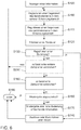
- Fig. 6 finally shows a flowchart of a method for displaying information that facilitates the operation of a user interface 100.
- a step S100 information is displayed on the display element 110 or the display surface 140.
- step S110 an attempt is made to register the presence of the touch element 150 in the detection area 170.
- a time period is correspondingly recorded in step S120.
- step S130 an attempt is made to register a touch. If one has been registered here, the action associated with the touch is triggered or carried out in a step S140 before the method ends in a step S150.
- step 160 it is checked in step 160 whether the predetermined time has elapsed. If this is the case, information which facilitates the operation of the operating interface 100 can be reproduced on the display element 110 before the method ends again in step S150. If, on the other hand, this is not the case, that is to say if the predetermined period of time has not yet elapsed, a return can take place after step S100 of displaying the information, so that, for example, the presence of the touch element in the detection area 170 is registered again, the time period is recorded and a check is carried out again the presence of a touch can be performed.
- a check can of course take place in a step S180 between checking whether the predetermined period of time has passed (step S160) and playing back the information in step S170 as to whether playback is switched off. If this is not the case, the information can be reproduced accordingly in step S170, while in the other case the method can be ended in step S150.
- the method described above is one that can be implemented, for example, using a single-stage proximity sensor. But even in the context of a two-stage sensor, this method, as it is related to Fig. 6 has been described so far. However, it can also additionally include registering a presence of the touch element in the further detection area 180 in the context of a step S190, which can be carried out, for example, after the information has been displayed on the display element, step S100. Likewise can in a step S200, it is checked whether the predetermined additional time has passed without a touch being registered. Step S200 can thus be carried out, for example, after step S130 of checking whether a touch has been registered.
- the display of information on the display element 110 can also be changed or immediately after going through, for example, steps S160 and S180 as part of step S170. the further information facilitating the operation of the operating interface 100 is displayed. If, on the other hand, this is not the case, a return to a step can accordingly take place after the information is displayed on the display element 110 in step S100.
- aspects have been described in connection with a device, it goes without saying that these aspects also represent a description of the corresponding method, so that a block or a component of a device is also to be understood as a corresponding method step or as a feature of a method step. Analogously, aspects that have been described in connection with or as a method step also represent a description of a corresponding block or details or features of a corresponding device.
- exemplary embodiments of the invention can be implemented in hardware or in software.
- the implementation can be carried out using a digital storage medium, for example a floppy disk, a DVD, a blue-ray disc, a CD, a ROM, a PROM, an EPROM, an EEPROM or a FLASH memory, a hard disk or another magnetic or optical Be carried out memory on which electronically readable control signals are stored, which can interact with a programmable hardware component or cooperate in such a way that the respective method is carried out.
- a digital storage medium for example a floppy disk, a DVD, a blue-ray disc, a CD, a ROM, a PROM, an EPROM, an EEPROM or a FLASH memory, a hard disk or another magnetic or optical Be carried out memory on which electronically readable control signals are stored, which can interact with a programmable hardware component or cooperate in such a way that the respective method is carried out.
- CPU Central Processing Unit
- GPU Graphics Processing Unit
- ASIC Application-Specific Integrated Circuit
- IC integrated Circuit
- SOC System on Chip
- FPGA Field Programmable Gate Array
- the digital storage medium can therefore be machine or computer readable.
- Some exemplary embodiments thus comprise a data carrier which has electronically readable control signals which are able to interact with a programmable computer system or a programmable hardware component in such a way that one of the methods described herein is carried out.
- An embodiment is thus a data carrier (or a digital storage medium or a computer-readable medium) on which the program for performing one of the methods described herein is recorded.
- exemplary embodiments of the present invention can be implemented as a program, firmware, computer program or computer program product with a program code or as data, the program code or the data being or being effective in performing one of the methods when the program is on a processor or programmable hardware component expires.
- the program code or the data can, for example, also be stored on a machine-readable carrier or data carrier.
- the program code or the data can be present, inter alia, as source code, machine code or byte code and as another intermediate code.
- Another exemplary embodiment is also a data stream, a signal sequence or a sequence of signals which represents the program for performing one of the methods described herein.
- the data stream, the signal sequence or the sequence of signals can, for example, be configured to be transferred via a data communication connection, for example via the Internet or another network.
- Exemplary embodiments are also signal sequences representing data which are suitable for transmission over a network or a data communication connection, the data representing the program.
- a program can implement one of the methods during its implementation, for example, by reading out memory locations or writing a date or more data into them, which may result in switching operations or other operations in transistor structures, in amplifier structures or in other electrical, optical, magnetic or components working according to a different functional principle. Accordingly, data, values, sensor values or other information can be recorded, determined or measured by a program by reading out a memory location.
- a program can therefore capture, determine or measure sizes, values, measured variables and other information by reading out one or more storage locations, as well as cause, initiate or carry out an action by writing to one or more storage locations and control other devices, machines and components .
Landscapes
- Engineering & Computer Science (AREA)
- Theoretical Computer Science (AREA)
- General Engineering & Computer Science (AREA)
- Physics & Mathematics (AREA)
- General Physics & Mathematics (AREA)
- Human Computer Interaction (AREA)
- Mechanical Engineering (AREA)
- Transportation (AREA)
- Combustion & Propulsion (AREA)
- Chemical & Material Sciences (AREA)
- Automation & Control Theory (AREA)
- User Interface Of Digital Computer (AREA)
- Position Input By Displaying (AREA)
Claims (15)
- Interface utilisateur (100) comprenant les éléments caractéristiques suivants :un élément d'affichage tactile (110) et au moins un capteur (120), lesquels sont conçus pour afficher une information sur l'élément d'affichage (110) à destination d'un utilisateur afin d'enregistrer un contact de l'élément d'affichage (110) avec un élément tactile (150) par le biais de l'utilisateur et pour enregistrer la présence de l'élément tactile (150) dans une zone de détection (170), la zone de détection (170) étant contiguë à un côté de l'élément d'affichage (110) qui est tourné vers l'utilisateur ; etun circuit de commande (130) qui est conçu pour commander l'élément d'affichage (110) de manière à ce que celui-ci reproduise sur l'élément d'affichage (110) une information qui facilite le fonctionnement de l'interface utilisateur (100) si l'élément tactile (150) se trouve dans la zone de détection (170) pendant une durée prédéterminée sans que le contact de l'élément d'affichage (110) ait été enregistré pendant ce temps, le circuit de commande (130) étant conçu pour commander l'élément d'affichage (110) de manière à ce que la reproduction de l'information facilitant le fonctionnement comprenne la mise en évidence optique d'au moins un élément de commande virtuel (190) présenté sur l'élément d'affichage.
- Interface utilisateur (100) selon la revendication 1, dans laquelle l'élément d'affichage tactile (110) et l'au moins un capteur (120) sont conçus de telle sorte que la zone de détection (170) contiennent sensiblement complètement l'élément d'affichage tactile (110) de sorte que l'élément tactile (150) passe dans la zone de détection (170) lorsque l'utilisateur déplace l'élément tactile (150) vers l'élément d'affichage tactile (110).
- Interface utilisateur (100) selon l'une des revendications précédentes, dans laquelle le circuit de commande (130) est conçu de telle sorte que la durée prédéterminée soit d'au moins 3 s.
- Interface utilisateur (100) selon l'une des revendications précédentes, dans laquelle le circuit de commande (130) est conçu de telle sorte que la durée prédéterminée est indépendante du mouvement de l'élément tactile (150) dans ou à travers la zone de détection (170).
- Interface utilisateur (100) selon l'une des revendications précédentes, la mise en évidence optique d'au moins un élément de commande virtuel (190) présenté sur l'élément d'affichage comprenant par exemple l'affichage d'un bord de l'au moins un élément de commande virtuel (190) avec des lignes plus épaisses et/ou colorées, par exemple l'affichage en couleur de l'au moins un élément de commande virtuel (190), par exemple l'affichage agrandi de l'au moins un élément de commande virtuel (190), par exemple l'affichage de l'au moins un élément de commande virtuel (190) dans une présentation tridimensionnelle ou tridimensionnelle intensifiée, par exemple l'affichage discontinu de l'au moins un élément de commande virtuel (190) et/ou par exemple l'affichage de l'au moins un élément de commande virtuel (190) avec un phénomène d'éclairage entourant le bord de l'au moins un élément de commande virtuel (190) et/ou le circuit de commande (130) étant conçu pour commander l'élément d'affichage (110) de telle sorte que la reproduction de l'information facilitant le fonctionnement comprend une présentation d'un menu auxiliaire et/ou d'un affichage auxiliaire.
- Interface utilisateur (100) selon l'une des revendications précédentes, dans laquelle le circuit de commande (130) est conçu pour permettre la désactivation de la reproduction de l'information facilitant le fonctionnement de l'interface utilisateur (100) .
- Interface utilisateur (100) selon l'une des revendications précédentes, dans laquelle l'élément d'affichage tactile (110) et l'au moins un capteur (120) sont en outre conçus pour enregistrer la présence de l'élément tactile (150) dans une autre zone de détection (180), l'autre zone de détection (180) étant contiguë à la zone de détection (170) sur un côté dirigé vers l'utilisateur, et le circuit de commande (130) étant conçu pour commander l'élément d'affichage (110) de manière à ce que celui-ci reproduise une information supplémentaire facilitant le fonctionnement de l'interface utilisateur (100) si l'élément tactile (150) se trouve dans la zone de détection supplémentaire (180) et dans la zone de détection (170) pendant une durée prédéterminée supplémentaire sans que le contact de l'élément d'affichage (110) ait été enregistré pendant ce temps.
- Interface utilisateur (100) selon la revendication 7, dans laquelle l'élément d'affichage tactile (110) et l'au moins un capteur (110) sont conçus de telle sorte que la zone de détection supplémentaire (180) contiennent sensiblement complètement la zone de détection (170) de sorte que l'élément tactile (150) passe dans l'autre zone de détection (180) lorsque l'utilisateur déplace l'élément tactile (150) jusque dans la zone de détection (170).
- Interface utilisateur (100) selon l'une des revendications 7 et 8, dans laquelle le circuit de commande (130) est conçu de telle sorte que la durée prédéterminée supplémentaire soit d'au moins 3 s.
- Interface utilisateur (100) selon l'une des revendications 7 à 9, dans laquelle le circuit de commande (130) est conçu de telle sorte que la durée prédéterminée supplémentaire soit indépendante du mouvement de l'élément tactile (150) dans ou à travers la zone de détection supplémentaire (180).
- Interface utilisateur (100) selon l'une des revendications 7 à 10, dans laquelle le circuit de commande (130) est conçu pour commander l'élément d'affichage (110) de telle sorte que la reproduction de l'information supplémentaire facilitant le fonctionnement de l'interface utilisateur (100) comprend une mise en évidence discrète d'au moins un élément de commande virtuel (190) présenté sur l'élément d'affichage (110), par exemple par l'affichage d'un bord de l'au moins un élément de commande virtuel (190) avec des lignes plus épaisses et/ou colorées, par exemple par l'affichage en couleur de l'au moins un élément de commande virtuel (190), par exemple par l'affichage agrandi de l'au moins un élément de commande virtuel (190), par exemple par l'affichage de l'au moins un élément de commande virtuel (190) dans une présentation tridimensionnelle ou tridimensionnelle intensifiée, par exemple par l'affichage discontinu de l'au moins un élément de commande virtuel (190) et/ou par exemple par l'affichage de l'au moins un élément de commande virtuel (190) avec un phénomène d'éclairage entourant le bord de l'au moins un élément de commande virtuel (190) et/ou dans laquelle le circuit de commande (130) est conçu pour commander l'élément d'affichage (110) de telle sorte que la reproduction de l'information supplémentaire facilitant le fonctionnement comprenne une présentation d'un menu auxiliaire et/ou d'un affichage auxiliaire.
- Interface utilisateur (100) selon l'une des revendications précédentes, dans laquelle l'élément d'affichage tactile (110) et l'au moins un capteur (120) sont conçus de telle sorte que l'élément tactile (150) comprenne au moins une partie d'un doigt (160) et/ou au moins une partie d'une main.
- Procédé d'affichage d'une information facilitant le fonctionnement d'une interface utilisateur (100), ledit procédé comprenant les étapes suivantes :afficher (S100) une information sur un élément d'affichage tactile (110) de l'interface utilisateur ;enregistrer (S110) la présence d'un élément tactile (150) dans une zone de détection (170), la zone de détection (170) étant contiguë à un côté de l'élément d'affichage (110) dirigé vers l'utilisateur ;reproduire (S170) l'information facilitant le fonctionnement de l'interface utilisateur (100) par mise en évidence optique d'au moins un élément de commande virtuel (190) présenté sur l'élément d'affichage si l'élément tactile (150) se trouve dans la zone de détection (170) pendant une durée prédéterminée sans que le contact de l'élément d'affichage (110) ait été enregistré.
- Procédé selon la revendication 13, comprenant en outre l'enregistrement (S130) d'un contact de l'élément d'affichage tactile (110) avec l'élément tactile (150) par le biais de l'utilisateur.
- Programme comprenant un code de programme pour mettre en œuvre l'un des procédés selon la revendication 13 ou 14, si le code de programme est exécuté sur un ordinateur, un processeur ou un composant matériel programmable.
Applications Claiming Priority (2)
| Application Number | Priority Date | Filing Date | Title |
|---|---|---|---|
| DE102012014910.7A DE102012014910A1 (de) | 2012-07-27 | 2012-07-27 | Bedienschnittstelle, Verfahren zum Anzeigen einer eine Bedienung einer Bedienschnittstelle erleichternden Information und Programm |
| PCT/EP2013/065433 WO2014016256A1 (fr) | 2012-07-27 | 2013-07-22 | Interface de commande, procédé d'affichage d'une information facilitant l'utilisation d'une interface de commande et programme |
Publications (2)
| Publication Number | Publication Date |
|---|---|
| EP2877362A1 EP2877362A1 (fr) | 2015-06-03 |
| EP2877362B1 true EP2877362B1 (fr) | 2020-03-25 |
Family
ID=48875020
Family Applications (1)
| Application Number | Title | Priority Date | Filing Date |
|---|---|---|---|
| EP13741717.6A Active EP2877362B1 (fr) | 2012-07-27 | 2013-07-22 | Interface de commande, procédé d'affichage d'une information facilitant l'utilisation d'une interface de commande et programme |
Country Status (7)
| Country | Link |
|---|---|
| US (1) | US20150212641A1 (fr) |
| EP (1) | EP2877362B1 (fr) |
| KR (2) | KR20170077275A (fr) |
| CN (1) | CN104619544B (fr) |
| DE (1) | DE102012014910A1 (fr) |
| ES (1) | ES2791770T3 (fr) |
| WO (1) | WO2014016256A1 (fr) |
Families Citing this family (22)
| Publication number | Priority date | Publication date | Assignee | Title |
|---|---|---|---|---|
| US20150347527A1 (en) * | 2014-05-27 | 2015-12-03 | GM Global Technology Operations LLC | Methods and systems for processing and displaying structured data |
| CN107079134A (zh) * | 2014-10-07 | 2017-08-18 | 松下知识产权经营株式会社 | 电子反射镜装置 |
| EP3035180B1 (fr) * | 2014-12-17 | 2018-08-08 | Volkswagen Aktiengesellschaft | Dispositif pour la commande de climatisation, véhicule, procédé et programme informatique destiné à la fourniture d'un signal vidéo et de commande |
| WO2016201485A1 (fr) * | 2015-06-15 | 2016-12-22 | Cana Technologies Pty Ltd | Procédé mis en œuvre par ordinateur, dispositif informatique de client et support d'informations lisible par ordinateur destiné à une présentation de données |
| CN106608188B (zh) * | 2015-10-22 | 2020-08-25 | 大陆汽车车身电子系统(芜湖)有限公司 | 基于虚拟开关的汽车电子功能控制方法 |
| WO2017200571A1 (fr) | 2016-05-16 | 2017-11-23 | Google Llc | Commande gestuelle d'une interface utilisateur |
| FR3065092B1 (fr) * | 2017-04-07 | 2019-06-14 | Peugeot Citroen Automobiles Sa | Procede de commande de vehicule par afficheur tactile |
| TW201907285A (zh) * | 2017-04-28 | 2019-02-16 | 日商松下知識產權經營股份有限公司 | 顯示裝置 |
| EP3489801A1 (fr) * | 2017-11-24 | 2019-05-29 | Thomson Licensing | Procédé et système de classement colorimétrique d'un contenu vidéo de réalité virtuelle |
| WO2019225516A1 (fr) * | 2018-05-22 | 2019-11-28 | 株式会社村上開明堂 | Dispositif d'affichage d'image virtuelle |
| EP3991067B1 (fr) | 2019-06-26 | 2025-02-26 | Google LLC | Rétroaction d'état d'authentification basée sur un radar |
| DE102019210912A1 (de) * | 2019-07-23 | 2021-01-28 | Brose Fahrzeugteile Se & Co. Kommanditgesellschaft, Bamberg | Verstellvorrichtung und Verfahren für die fremdkraftbetätigte Verstellung eines Verstellteils an einem Fahrzeug auf Basis wenigstens eines Bedienereignisses |
| CN113853567B (zh) | 2019-07-26 | 2024-03-29 | 谷歌有限责任公司 | 基于imu和雷达降低状态 |
| US11385722B2 (en) | 2019-07-26 | 2022-07-12 | Google Llc | Robust radar-based gesture-recognition by user equipment |
| JP7316383B2 (ja) | 2019-07-26 | 2023-07-27 | グーグル エルエルシー | Imuおよびレーダーを介した認証管理 |
| JP7346595B2 (ja) | 2019-07-26 | 2023-09-19 | グーグル エルエルシー | レーダーベースのジェスチャー認識の状況感知型制御 |
| US11868537B2 (en) | 2019-07-26 | 2024-01-09 | Google Llc | Robust radar-based gesture-recognition by user equipment |
| DE102019121843A1 (de) * | 2019-08-13 | 2021-02-18 | B.Braun Avitum Ag | Interface für ein medizinisches Gerät mit einem adaptiven Betätigungssensor |
| KR20220098805A (ko) * | 2019-08-30 | 2022-07-12 | 구글 엘엘씨 | 다중 입력 모드에 대한 입력 모드 통지 |
| KR102661485B1 (ko) | 2019-08-30 | 2024-04-29 | 구글 엘엘씨 | 일시정지된 레이더 제스처에 대한 시각적 표시자 |
| WO2021040745A1 (fr) | 2019-08-30 | 2021-03-04 | Google Llc | Procédés d'entrée pour dispositifs mobiles |
| US11467672B2 (en) | 2019-08-30 | 2022-10-11 | Google Llc | Context-sensitive control of radar-based gesture-recognition |
Citations (2)
| Publication number | Priority date | Publication date | Assignee | Title |
|---|---|---|---|---|
| CN1997958A (zh) * | 2004-06-29 | 2007-07-11 | 皇家飞利浦电子股份有限公司 | 图形用户界面的多层显示 |
| US20120013645A1 (en) * | 2010-07-19 | 2012-01-19 | Chen-Yang Hu | Display and method of displaying icon image |
Family Cites Families (28)
| Publication number | Priority date | Publication date | Assignee | Title |
|---|---|---|---|---|
| DE69232553T2 (de) * | 1991-05-31 | 2002-12-05 | Koninklijke Philips Electronics N.V., Eindhoven | Gerät mit einer Mensch-Maschine-Schnittstelle |
| US6009355A (en) | 1997-01-28 | 1999-12-28 | American Calcar Inc. | Multimedia information and control system for automobiles |
| KR20070036077A (ko) * | 2004-06-29 | 2007-04-02 | 코닌클리케 필립스 일렉트로닉스 엔.브이. | 그래픽 사용자 인터페이스의 다중층 디스플레이 |
| US8381135B2 (en) * | 2004-07-30 | 2013-02-19 | Apple Inc. | Proximity detector in handheld device |
| DE102007029618A1 (de) | 2006-12-21 | 2008-06-26 | Volkswagen Ag | Berührungslos aktivierbare Anzeige- und Bedienvorrichtung |
| US20080165145A1 (en) * | 2007-01-07 | 2008-07-10 | Scott Herz | Portable Multifunction Device, Method, and Graphical User Interface for Interpreting a Finger Swipe Gesture |
| US8665225B2 (en) * | 2007-01-07 | 2014-03-04 | Apple Inc. | Portable multifunction device, method, and graphical user interface for interpreting a finger gesture |
| US8432365B2 (en) * | 2007-08-30 | 2013-04-30 | Lg Electronics Inc. | Apparatus and method for providing feedback for three-dimensional touchscreen |
| RU2463245C2 (ru) * | 2008-05-08 | 2012-10-10 | Нестек С.А. | Средство для установки уровня наполнения чашки, используемое с устройством для разлива напитков |
| US9030418B2 (en) * | 2008-06-24 | 2015-05-12 | Lg Electronics Inc. | Mobile terminal capable of sensing proximity touch |
| KR100969790B1 (ko) * | 2008-09-02 | 2010-07-15 | 엘지전자 주식회사 | 이동단말기 및 그 컨텐츠 합성방법 |
| CA2639611A1 (fr) * | 2008-09-12 | 2010-03-12 | James Franklin Zdralek | Methode d'entree par gestuelle ambidextre, et systeme de commande |
| US8516397B2 (en) * | 2008-10-27 | 2013-08-20 | Verizon Patent And Licensing Inc. | Proximity interface apparatuses, systems, and methods |
| DE112009002462T5 (de) * | 2008-12-04 | 2012-05-31 | Mitsubishi Electric Corporation | Anzeigeeingabeeinrichtung |
| GB2466497B (en) * | 2008-12-24 | 2011-09-14 | Light Blue Optics Ltd | Touch sensitive holographic displays |
| DE102009019561A1 (de) * | 2009-04-30 | 2010-11-04 | Volkswagen Ag | Verfahren zum Anzeigen von Informationen in einem Kraftfahrzeug und Anzeigeeinrichtung |
| JP5282661B2 (ja) * | 2009-05-26 | 2013-09-04 | ソニー株式会社 | 情報処理装置、情報処理方法およびプログラム |
| KR101067814B1 (ko) * | 2009-09-30 | 2011-09-27 | 주식회사 팬택 | 이동통신단말기 및 이의 터치 인터페이스 제공 방법 |
| KR101092722B1 (ko) * | 2009-12-02 | 2011-12-09 | 현대자동차주식회사 | 차량의 멀티미디어 시스템 조작용 사용자 인터페이스 장치 |
| DE102009059867A1 (de) | 2009-12-21 | 2011-06-22 | Volkswagen AG, 38440 | Verfahren und Vorrichtung zum Bereitstellen einer graphischen Benutzerschnittstelle |
| DE112010005192T5 (de) * | 2010-01-29 | 2012-11-08 | Mitsubishi Electric Corporation | Karteninformations-Verarbeitungsvorrichtung |
| GB201013117D0 (en) * | 2010-08-04 | 2010-09-22 | Elliptic Laboratories As | Control of electronic devices |
| JP5652652B2 (ja) * | 2010-12-27 | 2015-01-14 | ソニー株式会社 | 表示制御装置および方法 |
| US8928635B2 (en) * | 2011-06-22 | 2015-01-06 | Apple Inc. | Active stylus |
| CN104285202B (zh) * | 2012-03-14 | 2018-02-02 | 诺基亚技术有限公司 | 触屏悬停输入处理方法和装置 |
| TWI464640B (zh) * | 2012-04-03 | 2014-12-11 | Wistron Corp | 手勢感測裝置及具有手勢輸入功能的電子系統 |
| CN102707885B (zh) * | 2012-05-02 | 2016-04-13 | 华为终端有限公司 | 一种触摸屏的操作方法及终端 |
| US20140006944A1 (en) * | 2012-07-02 | 2014-01-02 | Microsoft Corporation | Visual UI Guide Triggered by User Actions |
-
2012
- 2012-07-27 DE DE102012014910.7A patent/DE102012014910A1/de not_active Withdrawn
-
2013
- 2013-07-22 ES ES13741717T patent/ES2791770T3/es active Active
- 2013-07-22 EP EP13741717.6A patent/EP2877362B1/fr active Active
- 2013-07-22 KR KR1020177017337A patent/KR20170077275A/ko not_active Ceased
- 2013-07-22 CN CN201380039954.7A patent/CN104619544B/zh active Active
- 2013-07-22 WO PCT/EP2013/065433 patent/WO2014016256A1/fr not_active Ceased
- 2013-07-22 KR KR20157003066A patent/KR20150032324A/ko not_active Ceased
- 2013-07-22 US US14/417,319 patent/US20150212641A1/en not_active Abandoned
Patent Citations (2)
| Publication number | Priority date | Publication date | Assignee | Title |
|---|---|---|---|---|
| CN1997958A (zh) * | 2004-06-29 | 2007-07-11 | 皇家飞利浦电子股份有限公司 | 图形用户界面的多层显示 |
| US20120013645A1 (en) * | 2010-07-19 | 2012-01-19 | Chen-Yang Hu | Display and method of displaying icon image |
Also Published As
| Publication number | Publication date |
|---|---|
| DE102012014910A1 (de) | 2014-01-30 |
| US20150212641A1 (en) | 2015-07-30 |
| KR20150032324A (ko) | 2015-03-25 |
| EP2877362A1 (fr) | 2015-06-03 |
| CN104619544B (zh) | 2020-01-10 |
| WO2014016256A1 (fr) | 2014-01-30 |
| CN104619544A (zh) | 2015-05-13 |
| KR20170077275A (ko) | 2017-07-05 |
| ES2791770T3 (es) | 2020-11-05 |
Similar Documents
| Publication | Publication Date | Title |
|---|---|---|
| WO2014016256A1 (fr) | Interface de commande, procédé d'affichage d'une information facilitant l'utilisation d'une interface de commande et programme | |
| EP2121372B1 (fr) | Dispositif d'affichage et de commande pouvant etre active sans contact | |
| EP2424743B1 (fr) | Procédé pour afficher et entrer des informations dans un véhicule à moteur et dispositif d'affichage | |
| EP2179346B1 (fr) | Dispositif de visualisation et de commande pour véhicule automobile, à dispositif de visualisation multivues | |
| EP2750914B1 (fr) | Procédé et dispositif de mise à disposition d'une interface utilisateur, en particulier dans un véhicule | |
| WO2008138638A1 (fr) | Dispositif d'affichage et de commande multifonction et procédé permettant de faire fonctionner un dispositif d'affichage et de commande multifonction avec une meilleure commande de sélection | |
| EP2350799A1 (fr) | Procédé et dispositif d'affichage d'informations ordonnées sous forme de liste | |
| DE112022002985T5 (de) | Verfahren, system und computerprogramm zur berührungsstabilisierung | |
| DE102008048825A9 (de) | Anzeige- und Bediensystem in einem Kraftfahrzeug mit nutzerbeeinflussbarer Darstellung von Anzeigeobjekten sowie Verfahren zum Betreiben eines solchen Anzeige- und Bediensystems | |
| EP3642695B1 (fr) | Procédé de fonctionnement d'un dispositif d'affichage ainsi qu'un véhicule automobile | |
| DE102016224246B4 (de) | Verfahren und Vorrichtung zur Interaktion mit einer grafischen Benutzerschnittstelle | |
| WO2019072512A1 (fr) | Procédé de fourniture d'une réponse haptique à un opérateur d'un dispositif d'affichage tactile | |
| DE102012206247A1 (de) | Verfahren und Vorrichtung zur Anzeige einer Hand eines Bedieners eines Bedienelements eines Fahrzeugs | |
| EP2930603B1 (fr) | Procédé et dispositif de préparation d'une interface utilisateur graphique dans un véhicule | |
| EP3270278A1 (fr) | Procede de fonctionnement d'un systeme de commande et systeme de commande | |
| DE102013000069B4 (de) | Kraftfahrzeug-Bedienschnittstelle mit einem Bedienelement zum Erfassen einer Bedienhandlung | |
| DE102019218386B4 (de) | Verfahren und Vorrichtung zum Einstellen einer Position eines verstellbaren Fahrzeugteils | |
| DE102009057081A1 (de) | Verfahren zum Bereitstellen einer Benutzerschnittstelle | |
| EP2808775B1 (fr) | Contrôleur pour un système d'affichage d'informations pour un véhicule | |
| WO2018086826A1 (fr) | Procédé de fonctionnement d'un système de commande utilisateur et système de commande utilisateur | |
| DE102007012828A1 (de) | Informationssystem und Verfahren zum Bereitstellen von Informationen in einem Kraftfahrzeug mit verbesserter Bedienbarkeit | |
| DE102012218155A1 (de) | Erleichtern der Eingabe auf einer berührungsempfindlichen Anzeige in einem Fahrzeug | |
| EP2917062B1 (fr) | Procédé d'affichage d'informations dans un véhicule et dispositif de commande de l'affichage | |
| DE102012016110B4 (de) | Verfahren zum Bereitstellen einer Bedienvorrichtung in einem Fahrzeug und Bedienvorrichtung hierfür | |
| EP2107456B1 (fr) | Sélection de modes d'affichage SKINS pour un système d'info-spectacle |
Legal Events
| Date | Code | Title | Description |
|---|---|---|---|
| PUAI | Public reference made under article 153(3) epc to a published international application that has entered the european phase |
Free format text: ORIGINAL CODE: 0009012 |
|
| 17P | Request for examination filed |
Effective date: 20150227 |
|
| AK | Designated contracting states |
Kind code of ref document: A1 Designated state(s): AL AT BE BG CH CY CZ DE DK EE ES FI FR GB GR HR HU IE IS IT LI LT LU LV MC MK MT NL NO PL PT RO RS SE SI SK SM TR |
|
| AX | Request for extension of the european patent |
Extension state: BA ME |
|
| DAX | Request for extension of the european patent (deleted) | ||
| STAA | Information on the status of an ep patent application or granted ep patent |
Free format text: STATUS: EXAMINATION IS IN PROGRESS |
|
| 17Q | First examination report despatched |
Effective date: 20190529 |
|
| GRAP | Despatch of communication of intention to grant a patent |
Free format text: ORIGINAL CODE: EPIDOSNIGR1 |
|
| STAA | Information on the status of an ep patent application or granted ep patent |
Free format text: STATUS: GRANT OF PATENT IS INTENDED |
|
| INTG | Intention to grant announced |
Effective date: 20191217 |
|
| GRAS | Grant fee paid |
Free format text: ORIGINAL CODE: EPIDOSNIGR3 |
|
| GRAA | (expected) grant |
Free format text: ORIGINAL CODE: 0009210 |
|
| STAA | Information on the status of an ep patent application or granted ep patent |
Free format text: STATUS: THE PATENT HAS BEEN GRANTED |
|
| AK | Designated contracting states |
Kind code of ref document: B1 Designated state(s): AL AT BE BG CH CY CZ DE DK EE ES FI FR GB GR HR HU IE IS IT LI LT LU LV MC MK MT NL NO PL PT RO RS SE SI SK SM TR |
|
| REG | Reference to a national code |
Ref country code: GB Ref legal event code: FG4D Free format text: NOT ENGLISH |
|
| REG | Reference to a national code |
Ref country code: AT Ref legal event code: REF Ref document number: 1248186 Country of ref document: AT Kind code of ref document: T Effective date: 20200415 Ref country code: IE Ref legal event code: FG4D Free format text: LANGUAGE OF EP DOCUMENT: GERMAN |
|
| REG | Reference to a national code |
Ref country code: DE Ref legal event code: R096 Ref document number: 502013014488 Country of ref document: DE |
|
| PG25 | Lapsed in a contracting state [announced via postgrant information from national office to epo] |
Ref country code: RS Free format text: LAPSE BECAUSE OF FAILURE TO SUBMIT A TRANSLATION OF THE DESCRIPTION OR TO PAY THE FEE WITHIN THE PRESCRIBED TIME-LIMIT Effective date: 20200325 Ref country code: NO Free format text: LAPSE BECAUSE OF FAILURE TO SUBMIT A TRANSLATION OF THE DESCRIPTION OR TO PAY THE FEE WITHIN THE PRESCRIBED TIME-LIMIT Effective date: 20200625 Ref country code: FI Free format text: LAPSE BECAUSE OF FAILURE TO SUBMIT A TRANSLATION OF THE DESCRIPTION OR TO PAY THE FEE WITHIN THE PRESCRIBED TIME-LIMIT Effective date: 20200325 |
|
| PG25 | Lapsed in a contracting state [announced via postgrant information from national office to epo] |
Ref country code: GR Free format text: LAPSE BECAUSE OF FAILURE TO SUBMIT A TRANSLATION OF THE DESCRIPTION OR TO PAY THE FEE WITHIN THE PRESCRIBED TIME-LIMIT Effective date: 20200626 Ref country code: BG Free format text: LAPSE BECAUSE OF FAILURE TO SUBMIT A TRANSLATION OF THE DESCRIPTION OR TO PAY THE FEE WITHIN THE PRESCRIBED TIME-LIMIT Effective date: 20200625 Ref country code: HR Free format text: LAPSE BECAUSE OF FAILURE TO SUBMIT A TRANSLATION OF THE DESCRIPTION OR TO PAY THE FEE WITHIN THE PRESCRIBED TIME-LIMIT Effective date: 20200325 Ref country code: LV Free format text: LAPSE BECAUSE OF FAILURE TO SUBMIT A TRANSLATION OF THE DESCRIPTION OR TO PAY THE FEE WITHIN THE PRESCRIBED TIME-LIMIT Effective date: 20200325 Ref country code: SE Free format text: LAPSE BECAUSE OF FAILURE TO SUBMIT A TRANSLATION OF THE DESCRIPTION OR TO PAY THE FEE WITHIN THE PRESCRIBED TIME-LIMIT Effective date: 20200325 |
|
| REG | Reference to a national code |
Ref country code: NL Ref legal event code: MP Effective date: 20200325 |
|
| REG | Reference to a national code |
Ref country code: LT Ref legal event code: MG4D |
|
| PG25 | Lapsed in a contracting state [announced via postgrant information from national office to epo] |
Ref country code: NL Free format text: LAPSE BECAUSE OF FAILURE TO SUBMIT A TRANSLATION OF THE DESCRIPTION OR TO PAY THE FEE WITHIN THE PRESCRIBED TIME-LIMIT Effective date: 20200325 |
|
| PG25 | Lapsed in a contracting state [announced via postgrant information from national office to epo] |
Ref country code: SK Free format text: LAPSE BECAUSE OF FAILURE TO SUBMIT A TRANSLATION OF THE DESCRIPTION OR TO PAY THE FEE WITHIN THE PRESCRIBED TIME-LIMIT Effective date: 20200325 Ref country code: IS Free format text: LAPSE BECAUSE OF FAILURE TO SUBMIT A TRANSLATION OF THE DESCRIPTION OR TO PAY THE FEE WITHIN THE PRESCRIBED TIME-LIMIT Effective date: 20200725 Ref country code: RO Free format text: LAPSE BECAUSE OF FAILURE TO SUBMIT A TRANSLATION OF THE DESCRIPTION OR TO PAY THE FEE WITHIN THE PRESCRIBED TIME-LIMIT Effective date: 20200325 Ref country code: LT Free format text: LAPSE BECAUSE OF FAILURE TO SUBMIT A TRANSLATION OF THE DESCRIPTION OR TO PAY THE FEE WITHIN THE PRESCRIBED TIME-LIMIT Effective date: 20200325 Ref country code: PT Free format text: LAPSE BECAUSE OF FAILURE TO SUBMIT A TRANSLATION OF THE DESCRIPTION OR TO PAY THE FEE WITHIN THE PRESCRIBED TIME-LIMIT Effective date: 20200818 Ref country code: SM Free format text: LAPSE BECAUSE OF FAILURE TO SUBMIT A TRANSLATION OF THE DESCRIPTION OR TO PAY THE FEE WITHIN THE PRESCRIBED TIME-LIMIT Effective date: 20200325 Ref country code: EE Free format text: LAPSE BECAUSE OF FAILURE TO SUBMIT A TRANSLATION OF THE DESCRIPTION OR TO PAY THE FEE WITHIN THE PRESCRIBED TIME-LIMIT Effective date: 20200325 |
|
| REG | Reference to a national code |
Ref country code: ES Ref legal event code: FG2A Ref document number: 2791770 Country of ref document: ES Kind code of ref document: T3 Effective date: 20201105 |
|
| REG | Reference to a national code |
Ref country code: DE Ref legal event code: R097 Ref document number: 502013014488 Country of ref document: DE |
|
| PG25 | Lapsed in a contracting state [announced via postgrant information from national office to epo] |
Ref country code: DK Free format text: LAPSE BECAUSE OF FAILURE TO SUBMIT A TRANSLATION OF THE DESCRIPTION OR TO PAY THE FEE WITHIN THE PRESCRIBED TIME-LIMIT Effective date: 20200325 |
|
| PLBE | No opposition filed within time limit |
Free format text: ORIGINAL CODE: 0009261 |
|
| STAA | Information on the status of an ep patent application or granted ep patent |
Free format text: STATUS: NO OPPOSITION FILED WITHIN TIME LIMIT |
|
| PG25 | Lapsed in a contracting state [announced via postgrant information from national office to epo] |
Ref country code: PL Free format text: LAPSE BECAUSE OF FAILURE TO SUBMIT A TRANSLATION OF THE DESCRIPTION OR TO PAY THE FEE WITHIN THE PRESCRIBED TIME-LIMIT Effective date: 20200325 Ref country code: MC Free format text: LAPSE BECAUSE OF FAILURE TO SUBMIT A TRANSLATION OF THE DESCRIPTION OR TO PAY THE FEE WITHIN THE PRESCRIBED TIME-LIMIT Effective date: 20200325 |
|
| REG | Reference to a national code |
Ref country code: CH Ref legal event code: PL |
|
| 26N | No opposition filed |
Effective date: 20210112 |
|
| REG | Reference to a national code |
Ref country code: BE Ref legal event code: MM Effective date: 20200731 |
|
| PG25 | Lapsed in a contracting state [announced via postgrant information from national office to epo] |
Ref country code: LU Free format text: LAPSE BECAUSE OF NON-PAYMENT OF DUE FEES Effective date: 20200722 Ref country code: LI Free format text: LAPSE BECAUSE OF NON-PAYMENT OF DUE FEES Effective date: 20200731 Ref country code: CH Free format text: LAPSE BECAUSE OF NON-PAYMENT OF DUE FEES Effective date: 20200731 |
|
| PG25 | Lapsed in a contracting state [announced via postgrant information from national office to epo] |
Ref country code: BE Free format text: LAPSE BECAUSE OF NON-PAYMENT OF DUE FEES Effective date: 20200731 Ref country code: SI Free format text: LAPSE BECAUSE OF FAILURE TO SUBMIT A TRANSLATION OF THE DESCRIPTION OR TO PAY THE FEE WITHIN THE PRESCRIBED TIME-LIMIT Effective date: 20200325 |
|
| PG25 | Lapsed in a contracting state [announced via postgrant information from national office to epo] |
Ref country code: IE Free format text: LAPSE BECAUSE OF NON-PAYMENT OF DUE FEES Effective date: 20200722 |
|
| REG | Reference to a national code |
Ref country code: AT Ref legal event code: MM01 Ref document number: 1248186 Country of ref document: AT Kind code of ref document: T Effective date: 20200722 |
|
| PG25 | Lapsed in a contracting state [announced via postgrant information from national office to epo] |
Ref country code: AT Free format text: LAPSE BECAUSE OF NON-PAYMENT OF DUE FEES Effective date: 20200722 |
|
| PG25 | Lapsed in a contracting state [announced via postgrant information from national office to epo] |
Ref country code: TR Free format text: LAPSE BECAUSE OF FAILURE TO SUBMIT A TRANSLATION OF THE DESCRIPTION OR TO PAY THE FEE WITHIN THE PRESCRIBED TIME-LIMIT Effective date: 20200325 Ref country code: MT Free format text: LAPSE BECAUSE OF FAILURE TO SUBMIT A TRANSLATION OF THE DESCRIPTION OR TO PAY THE FEE WITHIN THE PRESCRIBED TIME-LIMIT Effective date: 20200325 Ref country code: CY Free format text: LAPSE BECAUSE OF FAILURE TO SUBMIT A TRANSLATION OF THE DESCRIPTION OR TO PAY THE FEE WITHIN THE PRESCRIBED TIME-LIMIT Effective date: 20200325 |
|
| PG25 | Lapsed in a contracting state [announced via postgrant information from national office to epo] |
Ref country code: MK Free format text: LAPSE BECAUSE OF FAILURE TO SUBMIT A TRANSLATION OF THE DESCRIPTION OR TO PAY THE FEE WITHIN THE PRESCRIBED TIME-LIMIT Effective date: 20200325 Ref country code: AL Free format text: LAPSE BECAUSE OF FAILURE TO SUBMIT A TRANSLATION OF THE DESCRIPTION OR TO PAY THE FEE WITHIN THE PRESCRIBED TIME-LIMIT Effective date: 20200325 |
|
| P01 | Opt-out of the competence of the unified patent court (upc) registered |
Effective date: 20230523 |
|
| REG | Reference to a national code |
Ref country code: DE Ref legal event code: R079 Ref document number: 502013014488 Country of ref document: DE Free format text: PREVIOUS MAIN CLASS: B60K0037060000 Ipc: B60K0035100000 |
|
| PGFP | Annual fee paid to national office [announced via postgrant information from national office to epo] |
Ref country code: ES Payment date: 20250812 Year of fee payment: 13 |
|
| PGFP | Annual fee paid to national office [announced via postgrant information from national office to epo] |
Ref country code: DE Payment date: 20250731 Year of fee payment: 13 |
|
| PGFP | Annual fee paid to national office [announced via postgrant information from national office to epo] |
Ref country code: IT Payment date: 20250721 Year of fee payment: 13 |
|
| PGFP | Annual fee paid to national office [announced via postgrant information from national office to epo] |
Ref country code: GB Payment date: 20250722 Year of fee payment: 13 |
|
| PGFP | Annual fee paid to national office [announced via postgrant information from national office to epo] |
Ref country code: FR Payment date: 20250725 Year of fee payment: 13 |
|
| PGFP | Annual fee paid to national office [announced via postgrant information from national office to epo] |
Ref country code: CZ Payment date: 20250714 Year of fee payment: 13 |