EP2877377B1 - Soupape de freinage de parking avec signalisation de position incomplete du frein de parking - Google Patents
Soupape de freinage de parking avec signalisation de position incomplete du frein de parking Download PDFInfo
- Publication number
- EP2877377B1 EP2877377B1 EP13739432.6A EP13739432A EP2877377B1 EP 2877377 B1 EP2877377 B1 EP 2877377B1 EP 13739432 A EP13739432 A EP 13739432A EP 2877377 B1 EP2877377 B1 EP 2877377B1
- Authority
- EP
- European Patent Office
- Prior art keywords
- parking brake
- rocker arm
- brake device
- electrical signal
- parking
- Prior art date
- Legal status (The legal status is an assumption and is not a legal conclusion. Google has not performed a legal analysis and makes no representation as to the accuracy of the status listed.)
- Active
Links
Images




Classifications
-
- B—PERFORMING OPERATIONS; TRANSPORTING
- B60—VEHICLES IN GENERAL
- B60T—VEHICLE BRAKE CONTROL SYSTEMS OR PARTS THEREOF; BRAKE CONTROL SYSTEMS OR PARTS THEREOF, IN GENERAL; ARRANGEMENT OF BRAKING ELEMENTS ON VEHICLES IN GENERAL; PORTABLE DEVICES FOR PREVENTING UNWANTED MOVEMENT OF VEHICLES; VEHICLE MODIFICATIONS TO FACILITATE COOLING OF BRAKES
- B60T7/00—Brake-action initiating means
- B60T7/02—Brake-action initiating means for personal initiation
- B60T7/08—Brake-action initiating means for personal initiation hand actuated
- B60T7/085—Brake-action initiating means for personal initiation hand actuated by electrical means, e.g. travel, force sensors
-
- B—PERFORMING OPERATIONS; TRANSPORTING
- B60—VEHICLES IN GENERAL
- B60T—VEHICLE BRAKE CONTROL SYSTEMS OR PARTS THEREOF; BRAKE CONTROL SYSTEMS OR PARTS THEREOF, IN GENERAL; ARRANGEMENT OF BRAKING ELEMENTS ON VEHICLES IN GENERAL; PORTABLE DEVICES FOR PREVENTING UNWANTED MOVEMENT OF VEHICLES; VEHICLE MODIFICATIONS TO FACILITATE COOLING OF BRAKES
- B60T15/00—Construction arrangement, or operation of valves incorporated in power brake systems and not covered by groups B60T11/00 or B60T13/00
- B60T15/02—Application and release valves
- B60T15/04—Driver's valves
- B60T15/041—Driver's valves controlling auxiliary pressure brakes, e.g. parking or emergency brakes
-
- B—PERFORMING OPERATIONS; TRANSPORTING
- B60—VEHICLES IN GENERAL
- B60T—VEHICLE BRAKE CONTROL SYSTEMS OR PARTS THEREOF; BRAKE CONTROL SYSTEMS OR PARTS THEREOF, IN GENERAL; ARRANGEMENT OF BRAKING ELEMENTS ON VEHICLES IN GENERAL; PORTABLE DEVICES FOR PREVENTING UNWANTED MOVEMENT OF VEHICLES; VEHICLE MODIFICATIONS TO FACILITATE COOLING OF BRAKES
- B60T17/00—Component parts, details, or accessories of power brake systems not covered by groups B60T8/00, B60T13/00 or B60T15/00, or presenting other characteristic features
- B60T17/18—Safety devices; Monitoring
-
- B—PERFORMING OPERATIONS; TRANSPORTING
- B60—VEHICLES IN GENERAL
- B60T—VEHICLE BRAKE CONTROL SYSTEMS OR PARTS THEREOF; BRAKE CONTROL SYSTEMS OR PARTS THEREOF, IN GENERAL; ARRANGEMENT OF BRAKING ELEMENTS ON VEHICLES IN GENERAL; PORTABLE DEVICES FOR PREVENTING UNWANTED MOVEMENT OF VEHICLES; VEHICLE MODIFICATIONS TO FACILITATE COOLING OF BRAKES
- B60T17/00—Component parts, details, or accessories of power brake systems not covered by groups B60T8/00, B60T13/00 or B60T15/00, or presenting other characteristic features
- B60T17/18—Safety devices; Monitoring
- B60T17/22—Devices for monitoring or checking brake systems; Signal devices
- B60T17/221—Procedure or apparatus for checking or keeping in a correct functioning condition of brake systems
-
- B—PERFORMING OPERATIONS; TRANSPORTING
- B60—VEHICLES IN GENERAL
- B60T—VEHICLE BRAKE CONTROL SYSTEMS OR PARTS THEREOF; BRAKE CONTROL SYSTEMS OR PARTS THEREOF, IN GENERAL; ARRANGEMENT OF BRAKING ELEMENTS ON VEHICLES IN GENERAL; PORTABLE DEVICES FOR PREVENTING UNWANTED MOVEMENT OF VEHICLES; VEHICLE MODIFICATIONS TO FACILITATE COOLING OF BRAKES
- B60T7/00—Brake-action initiating means
- B60T7/02—Brake-action initiating means for personal initiation
- B60T7/08—Brake-action initiating means for personal initiation hand actuated
- B60T7/10—Disposition of hand control
- B60T7/102—Disposition of hand control by means of a tilting lever
- B60T7/104—Disposition of hand control by means of a tilting lever with a locking mechanism
Definitions
- the invention relates to a parking brake device of a vehicle having a pneumatic parking brake valve which has a connected to a shift gate of a valve housing in different pivot positions guided and connected to a control body for actuating a parking brake valve control lever, with a mechanism for locking and releasing a detent body with respect to a gate opening of the shift gate at least in a the operating state "parking" representing pivoting position of the operating lever, according to the preamble of claim 1.
- a parking brake valve is for example from the DE 3 431 559 A1 known. Such parking brake valves are used to operate a vehicle equipped with spring brake cylinders parking brake device or a combined parking and auxiliary brake device, which can be sensitively graded by operating the parking brake valve and can also be used to operate the trailer brake system.
- the operating lever of the parking brake valve is pivoted starting from a pivot position "driving" in a pivot position "auxiliary brakes", wherein in this rotation range a finely graded actuation of the parking and auxiliary brake device and controllable by the parking brake valve trailer brake system is possible.
- auxiliary brakes a finely graded actuation of the parking and auxiliary brake device and controllable by the parking brake valve trailer brake system.
- the operating lever can be moved further into a test or control position; in this position allows the parking brake valve with the parking brake control of the sole braking effect of the brake system of the towing vehicle with the brake released in the trailer.
- the pivoting movements of the operating lever under the leadership of the shift gate are performed with the help of a arranged at the outer end of the control lever shift handle, wherein the switching handle is immersed in pivoting the operating lever in the parking brake corresponding gate opening of the shift gate in this.
- the distance of the handle to the housing head so shortens something when the parking brake position is reached.
- the locking body can therefore only be unlocked when the control handle carrying it is pulled back to its original level directed outwards.
- it is therefore possible to pull the locking body out of the gate opening i. to raise to the level of the top of the shift gate, when the operating lever is to be pivoted from the range of the parking brake position in the driving or release position.
- the sensitivity in the parking brake valve actuation suffers, ie it may be problematic to make sure about whether the automatic detent is achieved in the parking position or not. This can not always be guaranteed that the Detent body is actually completely engaged in the gate opening despite located in the pivot position "Parking" operating lever, so that the operating lever due to the spring preload from the pivot position "Park” solve and can swing in the direction of travel or release position. If the driver then leaves the vehicle in the belief that a parking brake has been applied, there is a risk of the vehicle starting to move in an uncontrolled manner.
- a parking brake valve with signaling of a not fully achieved parking brake position of the DE 33 46 018 A1 known.
- a handbrake or parking brake device for vehicles is disclosed with a latchable in a parking or parking brake position by means of a locking member handle.
- This parking brake device has a monitoring device which monitors the complete engagement of the locking member. Only when fully latched detent member, a switching device for actuating an optical or acoustic control mark is turned on.
- the interaction of a locking member is described with a shift gate, but the mechanical components are technically much more complex in their entirety, which of course increases the cost of manufacturing.
- a plunger switch which, depending on the position of the shift rod for adjusting the parking brake valve, is actuated via a plunger and thus generates an electrical signal.
- this electrical signal is interrupted again in the test position of the shift rod, which can lead to misinterpretation of the operator.
- such a signal generation in an electronic evaluation of the signals is difficult, so that a misinterpretation of the signals can have serious consequences
- a generic parking brake device is in DE 33 46 018 A1 described. There, an electrical signal is generated on the status of the parking brake valve in the operating mode "Parking".
- the object of the present invention is to develop a parking brake device of the type mentioned in such a way that the security against unintentional incorrect operation is increased.
- the starting point of the invention is a parking brake device with a purely pneumatic-mechanical parking brake valve, wherein the operating lever is connected to a control body for actuating a parking brake valve mechanism.
- the parking brake valve mechanism may include, for example, a double seat valve with intake valve seat and exhaust valve seat.
- a co-operating with the locking body first sensor device is provided which is designed such that it depends on a complete or incomplete or not successful engagement of the detent body in the gate opening of the shift gate a first electrical signal for an electronic Evaluation device generated.
- This first electrical signal then serves as an indicator of whether the locking body is fully engaged in the gate opening or not. If the catch body is not or not fully engaged in the gate opening, so for example generates the first electrical signal for the evaluation device. Insignificant here is the signal level of this first electrical signal. Rather, it is essential that the presence of the first electrical signal and the absence of the first electrical signal corresponds to two distinguishable signal states with different signal levels and the two states - latching body fully engaged in the gate opening on the one hand and locking body in the gate opening not or not fully engaged - are clearly distinguishable from each other based on the corresponding signal level of the first electrical signal.
- the first electrical signal provides a clear information about the status of the parking brake valve in a pivot position of the operating lever, in which the locking body must engage in a gate opening and in particular whether the assumed pivot position of the operating lever is actually stable or not.
- the same principle can be transferred to other positions of the control lever of the parking brake valve except in the parking brake position, in which the detent body must engage in a gate opening.
- the electronic evaluation device is designed such that it receives and processes or evaluates, in addition to the first electrical signal, a second electrical signal of one or more second sensor devices which can be generated depending on an existing or non-existent access possibility of the driver of the vehicle or an operator on the control lever is, wherein the electronic evaluation device depending on the first electrical signal and the second electrical signal generates a visually and / or audible perceptible warning signal and / or an automatic application of the parking brake is caused.
- the first electrical signal generated by means of the first sensor device in an incomplete or not successful engagement of the detent body in the gate opening is then in the evaluation together with a second electrical signal or a plurality of second electrical signals from at least one second sensor device depending on an existing or not existing accessibility of the driver of the vehicle or an operator can be generated on the operating lever, then evaluated whether the optically and / or acoustically perceptible warning signal or an enable signal to be output from the evaluation.
- the evaluation device is designed such that it automatically applies the parking brakes of the vehicle or the parking brake actuators, for example by electrical actuation of one or more solenoid valves, through which the parking brake actuators, which as a rule are provided by passive spring brake cylinders, are vented and thus clamped become.
- a first electrical signal is controlled in the evaluation, because although the operating lever of the parking brake valve in the pivot position "Parking" is, but the locking body is incomplete or not fully engaged in the gate opening, a warning signal is generated whereupon a present on the driver's seat driver or an operator by a renewed actuation of the operating lever with complete engagement of the detent body can establish a stable pivot position "Parking".
- a second electrical signal or a plurality of second signals of at least one second sensor device in the Evaluation be controlled, which are an indication of whether the driver or an operator is on the driver's seat and / or in operating range for an actuation of the operating lever. If this is not the case, the optically and / or acoustically perceptible warning signal is further controlled by the evaluation device, which points to the above-described danger situation of an only unstably assumed parking brake position of the operating lever of the parking brake valve and / or the evaluation device an automatic application of the parking brake caused, for example by electrical control of vent solenoid valves.
- the sensor device comprises a contactlessly cooperating with the latching body sensor, for example, at least one Hall sensor.
- the first sensor device may also comprise a touch sensor, for example in the form of an electrical switch, with a switching member which can be contacted directly or indirectly by the latching body, wherein the electrical switch is arranged such that the switching element does not actuate the switch when the latching body is not or not completely latched into the gate opening can transfer from a first shift position to a second shift position, but transferred when fully engaged in the gate opening detent body from the first switching position to the second switching position.
- the first electrical signal is generated or not.
- the electronic evaluation device is designed to generate an optically and / or acoustically perceptible, a stably taken pivot position of the operating lever symbolizing release signal in the event of failure to generate and / or an omitted control of the first electrical signal, because then the detent body completely engaged in the gate opening.
- This release signal can for example consist in a flashing of a green lamp, which signals the driver that the locking body is fully engaged in the gate opening and therefore the example, the "parking" corresponding pivot position of the operating lever was stably taken.
- the electronic evaluation device can be designed such that it produces an optically and / or acoustically perceptible warning signal in the case of a completed generation and / or complete activation of the first electrical signal.
- This warning signal then indicates a generally unstable position of the operating lever, but then also in the pivot position of the operating lever deviating from the "parking" position. It is essential, however, that the driver receives a warning signal, for example, in the swivel position "parking" after placing the operating lever when the operating lever has not taken a stable parking position.
- a first electrical signal is controlled in the evaluation, because although the operating lever or the shift rod of the parking brake valve in the pivot position "parking" is, but the locking body is incomplete or not fully engaged in the gate opening, so the driver or an operator pointed to this fact by the warning signal and can intervene accordingly by the operating lever of the parking brake valve is actuated so that the locking body completely engages in the gate opening.
- the signals are already used in the vehicle already existing, described above second sensor devices as the second electrical signals for the evaluation device in an advantageous manner.
- the second embodiment can be realized, for example, by the first electrical signal, which points to a not fully or incompletely engaged in the gate opening detent body, and the second electrical signal, which indicates a non-intervention by the driver or an operator on the operating lever indicates the parking brake valve, in which the evaluation must be present in an AND gate cumulated to cause the evaluation, to generate the warning signal and / or automatically clamp the parking brake.
- a release signal can be generated by the evaluation device, if no first electrical signal from the first sensor device into the evaluation device is controlled to indicate a stable assumed pivot position of the operating lever of the parking brake valve.
- the first sensor device comprises a contact sensor, for example in the form of an electrical switch
- a spring element is provided as an operative connection between the switching element of the first sensor device and the detent body, which is designed and arranged so that when completely in the Gate opening latched locking body of the locking body exerts a force on the at least one spring element which transmits the force directly or indirectly to the switching element of the switch to transfer it from the first switching position to the second switching position.
- At least one spring element can be supported on at least one rocker arm pivotally mounted on the valve housing of a rocker mechanism, which can be brought into contact at least in the operating position "parking" of the operating lever with the latching element and on the other hand with the switching element of the switch.
- the at least one spring element includes a compressible compression spring, which is mounted between two rocker arms of the rocker mechanism, a first pivotable about a pivot axis rocker arm and a second rocker arm pivotable about a pivot axis, wherein the locking element when snapping into the gate opening with the first rocker arm in Contact device, which under pivotal movement about its pivot axis a compressive force on the at least exerts a spring element which compressively transmits the pressure force to the second rocker arm, the pivotal movement about its pivot axis contacts the switching member of the switch to transfer it from the first switching position to the second switching position.
- a compressible compression spring which is mounted between two rocker arms of the rocker mechanism, a first pivotable about a pivot axis rocker arm and a second rocker arm pivotable about a pivot axis
- the first and the second rocker arm on a common pivot axis, which simplifies the structure.
- a further spring element which is coupled on the one hand to the valve housing and on the other hand to the first rocker arm, can bias the first rocker arm, on the one hand, into contact with the detent body and, on the other hand, in contact with the second rocker arm.
- Two pins are also preferably arranged on the first rocker arm, of which a first pin has on the one hand a support surface for the at least one spring element and on the other hand a contact surface for the second rocker arm and a second pin has a contact surface for the latching body.
- the second rocker arm has a frame-shaped recess, into which projects the first pin of the first rocker arm, wherein the at least one spring element between the first pin and a support surface is received in the frame-shaped recess.
- a stop device which prevents a pivoting movement of the second rocker arm over a defined, a clear switching of the switch causing pivot position addition.
- This defined pivot position of the second tilt lever is in particular in the operating state "parking" before.
- the second rocker arm having a projection which contacts a limit stop on the valve housing in the operating state "parking” and then engaged in the gate opening latching body.
- the dimension of the second pin dimensioned such that the detent body both in the Operating state “parking” representing pivot position of the operating lever as well as in a operating state “test position” representing pivot position of the operating lever contacted the second pin, starting from the operating state “parking” representing pivot position of the locking body initially beyond the detent position in the gate opening radially inward is brought below the level of the shift gate with further compression of the at least one spring element and then slides by subsequent pivoting of the operating lever in the operating state "test position” representing pivoting position below the shift gate along.
- test position ie with the parking brake applied to the parking brake valve allows control of the sole braking effect of the spring brake system of the towing vehicle by the brake in the trailer is released for this purpose.
- the locking body remains during pivoting of the operating lever from the operating state "Parking" in the operating state "test position" in engagement with the first rocker arm or with its second pin and can, for example, slide along the contact surface of the second pin, while still the second rocker arm contacted the switching member of the switch to keep it the second switching position.
- the tensioned parking brake of the towing vehicle continues to be signaled.
- the transition from "parking" to "test position” mechanically steady, because the locking body remains in spite of pivoting of the operating lever in contact with the first rocker arm.
- the invention also relates to a vehicle which includes a parking brake device described above.
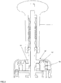
- Fig.1 is a cross-sectional view of a parking brake valve of a pneumatic-mechanical parking brake device of a commercial vehicle as part of a pneumatic or electro-pneumatic braking device of the commercial vehicle.
- At least one parking brake actuator of the commercial vehicle preferably in the form of a pneumatic spring brake cylinder for applying (parking position), is vented with the parking brake valve and ventilated for release (drive position). If the commercial vehicle is a towing vehicle of a tractor-trailer combination, then the parking brake valve is also used to operate the (operating) brake of the trailer via a likewise known trailer control valve.
- the parking brake valve can also assume a "test" position, in which it is tested whether the braked vehicle via the spring-loaded towing vehicle coupled with unbraked trailer can hold the tractor-trailer combination braked.
- the parking brake valve after Fig.1 has an operating lever 1 in cooperation with a shift gate 3.
- the control lever 1 acts on a (not shown) in the housing (not shown) housing head of the parking brake valve mounted control body 5 on a (not shown) valve mechanism, which preferably serves to control the auxiliary and parking brake system in commercial vehicles with trailer connection.
- the operating lever 1 is provided with a switching rod 7, which at her according to illustration Fig.1 Upper end of a switching handle 9 is surrounded.
- the switching handle 9 is connected to a switching sleeve 11, which extends as shown in a locking body 13.
- the switching handle 9 is pushed onto the shift sleeve 11 captive; It is also possible that the switching handle 9 is connected in a different way with the switching sleeve 11, so the handle can also be made of the same material with the switching sleeve.
- the protective sleeve 15 preferably comprises the latching body 13 which is supported by means of a locking spring 17 on a locking ring 19 connected to the switching sleeve.
- the Rastierfeder 17 can push the locking body 13 in the manner described below downwards, ie in the direction of the control body fifth
- a stop ring 21 is fixed on the inside, which is able to engage in downwardly directed movement of the detent body to a shoulder 23 of the shift sleeve 11.
- FIG.1 Upper region of the operating lever 1, two springs are provided within the control handle 9, an inner lifting spring 25 and an outer spring 27.
- the two springs are based on their view of the lower end of a slidably held on the shift rod 7 stop sleeve 29 from.
- the upper end of the lifting spring 25 is supported on a stop ring 31 connected to the shift rod 7, while the upper end of the spring 27 is supported on a shoulder 33 projecting from the shift sleeve 11 on the inside.
- the locking body 13 acts, as stated above, with the shift gate 3 together to set the shift positions of the parking brake valve.
- the structure known per se switching gate 3, which can be made as a simple stamped part, has a so-called cam slot 35 which extends from the lower end of the slot to an extended gate opening 37.
- cam slot 35 On both sides of serving for guiding the operating lever 1 cam slot 35 are guideways on which the in Fig.1 Locking body 13 shown between the positions A and B described below slides along, ie, as long as the shift rod 7 is within the guide portion of the cam slot 35.
- pressure point stops (not shown) can be provided on both sides.
- Position B auxiliary brake position
- Position C parking brake position
- the parking brake valve In the parking brake position according to position C, ie when the parking brake is engaged, the parking brake valve allows control of the sole braking action of the spring brake system of the vehicle by releasing the brake in the trailer for this purpose.
- the driver of the vehicle exercises in the parking brake position on the shift handle 9 according to a Fig.1 inward pressure.
- the shift lever 9 When the shift lever 9 is pressed inward in the parking brake position of the operating lever 1 (position C), then the shoulder 23 of the shift sleeve 11 engages after passing through the play S2 on the facing stop surface of the detent body 13, so that subsequently the shift sleeve 11 with the locking body 13 is directed inwardly displaceable.
- the detent body 13 is immersed so far inward that he now by following Pivoting the operating lever 1 below the level of the shift gate 3 can slide along and in this way in the position D is pivotable.
- the position D is the so-called. Test position, in which by means of a (not shown) valve mechanism, a ventilation of the trailer control valve leading line is completed. As a result, the brake is released in the trailer, so that the braking effect of the towing vehicle can be controlled alone. Also, this pivoting in the position D is done as in the previously described pivoting movements against the force of (not shown) return springs, which endeavor to return the operating lever 1 in the release or driving position A.
- Fig. 1 shown neutral intermediate position in which it is prevented from being pivoted under the action of (not shown) return springs in the position A, since it rests against the inner circumference of the gate opening 37.
- the operating lever 1 can consequently be pivoted back into the position A only when the detent body 13 has reproduced with reference to the position B, relative altitude to the shift gate 3, It is therefore necessary that the detent body on the top of the guideways 39 and 41st arrives.
- the locking body 13 which slides between the positions A and B under the tension of the detent 17 on the top of the shift gate 3 along, thus has the in Fig.1 reproduced distance corresponding to the Einrastweg S1 with respect to the lower end of the shift sleeve 11, ie with respect to the shoulder 23.
- the detent body 13 accordingly has that degree of freedom of movement, which he needs to 37 directed in the region of the slide opening relative to the shift sleeve 11 downward to be moved, that is in the in Fig. 1 illustrated altitude.
- Such a parking brake valve corresponds to the prior art, for example, according to the above-mentioned DE 34 31 559 A1 ,
- first sensor means 63 is provided, which is designed such that it depends on a complete or incomplete or not successful engagement of the detent body 13 in the gate opening 37 of the shift gate 3 a generates first electrical signal for an electronic evaluation device 65.
- This first electrical signal then serves as an indicator of whether the locking body 13 is fully engaged in the gate opening 37 or not. If the Detent body 13 is not or not fully engaged in the gate opening 37, so for example, the first electrical signal for in Figure 5 shown evaluation device 65 generated.
- the first electrical signal is a clear information about the status of the parking brake valve here in the pivot position "Parking" of the operating lever 1, in which the locking body 13 must engage in the gate opening 37 and on whether the assumed pivot position "Parking" of the operating lever 1 also is actually stable or not.
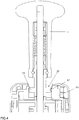
- the first sensor device 63 preferably comprises a touch sensor, for example in the form of an electrical switch, as in FIG Fig.2 and Figure 3
- the electric switch 63 is arranged such that the switching element, here, for example, a switching pin 67, the switch 63 not or not fully engaged in the gate opening 37 latching body 13 is not from a first switching position in a second switching position able to convict, but transferred in completely engaged in the gate opening 37 locking body 13 him from the first switching position to the second switching position.
- the first electrical signal is generated or not.
- the switch 63 is connected, for example, in an electrical circuit not shown here and separates or connects this electrical circuit depending on the switching state.
- Fig. 3 the situation is shown in the locking body 13 is not fully engaged in the position "parking" operating lever 1 in the gate opening 37 and therefore the locking body 13, the switching pin 67 Although almost contacted, but not the penetration depth of the detent body 13 in the gate opening 37 is large enough to switch the switch 63.
- the first electrical signal is produced here, for example, by not disconnecting the electrical circuit.
- the first electrical signal is according to Figure 5 in the electronic evaluation device 65 is controlled, which includes a microcomputer then generates a visually and / or audible perceptible warning signal 69.
- This warning signal 69 then indicates an unstable position of the operating lever 1 in the "parking" position and consists in particular in the illumination of a red warning light.
- the first sensor device here in the form of the switch 63, a first electrical signal is controlled in the evaluation device 65, because although the operating lever 1 of the parking brake valve in the pivot position "parking" is, but the detent body 13 is not or not completely in the gate opening 37 is engaged, the driver or an operator is informed of this circumstance by the warning signal 69 and can intervene accordingly by the operating lever 1 of the parking brake valve is actuated so that the locking body 13 completely engages in the gate opening 37.
- the latching body 13 is then fully engaged in the gate opening 37 after the actuating lever 1 has been set to the "parking" position, then the latching body 13 is already engaged in the gate opening 37 from the very beginning, as in FIG Figure 4 shown, the switching pin 67 detected by the detent body 13 such that the switch 63 switches and thus separates the electrical circuit.
- the first electrical signal is not generated, whereupon the evaluation device 65 generates a visually and / or acoustically perceptible, a stable assumed pivot position "Parking" of the operating lever 1 symbolizing release signal, because then the locking body 13 is fully engaged in the link opening 37 .
- This release signal may consist, for example, in a flashing of a green lamp, which signals to the driver that the detent body 13 is fully engaged in the gate opening 37 and therefore the example, the "parking" corresponding pivot position of the operating lever 1 was stably taken.
- the first sensor device 63 it is of course also possible to use, instead of a touch sensor, a sensor which interacts with the detent body 13 in a contactless manner, for example a Hall sensor.
- the electronic evaluation device 65 may be configured to receive and process or evaluate a second electrical signal from one or more second sensor devices 71 in addition to the first electrical signal.
- the second electrical signal is then generated depending on an existing or non-existent accessibility of the driver of the vehicle or an operator on the operating lever 1 and on the control handle 9.
- the evaluation device 65 then generates an optically and / or acoustically perceptible warning signal or an enable signal depending on the first electrical signal and the second electrical signal.
- the evaluation device 65 can cause an automatic application of at least one parking brake actuator 73 of the parking brake.
- the automatic application of the parking brake actuators 73 of the parking brake of the vehicle can be effected, for example, by electrical actuation of one or more solenoid valves 75, by means of which the parking brake actuators 73, which as a rule are provided by passive spring brake cylinders, are vented and thus clamped. This is in Figure 6 symbolizes.
- the first electrical signal generated by means of the first sensor device 63 in an incomplete or not successful engagement of the detent body 13 in the gate opening 37 is then in the evaluation device 65 together with the second electrical signal or a plurality of second electrical signals from the second sensor device or from the second sensor devices 71 depending on an existing or non-existent accessibility of the driver of the vehicle or an operator on the operating lever 1 can be generated, evaluated.
- the first electrical signal which indicates a not engaged or incompletely engaged in the gate opening 37 detent body 13
- the second electrical signal which indicates a non-existent intervention possibility by the driver or an operator on the Indicates operating lever 1 of the parking brake valve, cumulatively present in an AND gate implemented in the evaluation device 65 to generate the warning signal 69 and / or to automatically clamp the Parkbremsaktuatoren 73.
- the signals are already used in the vehicle already existing, described above second sensor devices 71 as the second electrical signals for the evaluation device 65.
- a release signal 69 can be generated by the evaluation device 65, if no first electrical signal from the first sensor device 63 is controlled in the evaluation device 65 to indicate a stable assumed pivot position of the operating lever 1 of the parking brake valve.
- the interaction between the operating lever 1 and the detent body 13 and the actuatable by direct or indirect contact switch 63 by means of a spring element 16 can be realized, wherein the detent body 13 acts on the switching element 67 of the switch 63 via the spring element 16 and In this case, a stable first electrical signal is generated, which is supplied to the evaluation device 65 for further processing.
- the spring element 16 preferably additionally cooperates with a rocker mechanism 2.
- an operative connection between the locking body 13 and the switching member 67 without the Kipphebelmechanismus 2 is conceivable.
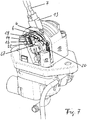
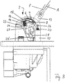
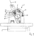
- FIGS. 7 to 11 Representations of a parking brake valve with a rocker mechanism 2 and a spring element 16 together with the first sensor device in the form of a microswitch 63.
- the rocker mechanism 2 is arranged laterally on a crankcase 10 as part of the valve housing of the parking brake valve.
- the rocker mechanism 2 has a first rocker arm 4 and a second rocker arm 6, which are arranged rotatably about a common pivot axis 8.
- the pivot axis 8 is with its one end in the housing wall of the crankcase 10 and with its other end in a in the FIGS. 7 to 11 only shown in its lower part supporting arm 12 of the crankcase 10 stored.
- the microswitch 63 is arranged below the second rocker arm 6 and in relation to the pivot axis 8, so that the second rocker arm 6 can act in a rotational movement on the switching member 67, here, for example, a button, in its direction of actuation here, for example, approximately perpendicular. As a result, switching contacts (not shown here) are actuated within the microswitch 63.
- the second rocker arm 6 has, spaced from the pivot axis 8, a frame-shaped recess 14 in which a spring element 16 is received under prestress as a compression spring, which is adjusted so that it protrudes into the recess 14 first pin 18 of the first Rocker arm 4 urges to an upper inner edge of the recess 14, whereby between the first rocker arm 4 and the second rocker arm 6 an elastic operative connection is made, which will be described in more detail below.
- first pin 18 is part of the end of the first rocker arm 4 and is connected to this example, undetachable, so that the first pin 18 and the rocker arm 4 are preferably made in one piece, for example, as an injection molded plastic.
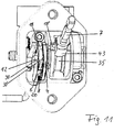
- a second preferably also with the first rocker arm 4 integral pin 18 'is arranged (see Fig. 11 ).
- the pivot axis 8 of the first rocker arm 4 is on the one hand the end with the two pins 18, 18 'and on the other hand, the end with the articulation of the further spring element 20 interposed ( Figure 8 ).
- the further spring element 20 is releasably secured with its one end to one end of the first rocker arm 4 in a bore 26 and with its other end on the valve housing.
- Figure 11 shows a perspective top view of the parking brake valve, with the operating lever 1 in the operating position "Parking". There, the cam slot 35 and the catch collar 43 is visible on the shift rod 7, and the side of the crankcase 10 arranged Kipphebelmechanismus 2 with first and second rocker arm 4, 6.
- the first and second rocker arms 4, 6 are preferably arranged directly and parallel side by side and to the common pivot axis 8 rotatably mounted, which is received on one side of the support arm 12 and on the other side of a side wall of the crankcase 10.
- the dimension (width) of the second pin 18 'in the actuating direction of the operating lever 1 is dimensioned so that the second pin 18' with the latching collar 43 continues to remain in sliding contact when the shift rod 7 brought into the operating position D "test position” and For this purpose, first by means of the control handle 9 is pressed down.
- the locking collar 43 therefore urges in the operating position C “parking” the second pin 18 'therefore first down and slides, after further urging the second pin 18' down the subsequent pivoting of the operating lever 1 in the operating position D "test position” on the second Pin 18 'along, which does not change its circumferential position with respect to the pivotal movement of the operating lever 1.
- the operating lever 1 or the shift rod 7 can now be moved to the operating position D "test position" to test the parking brake effect of the tractor to which the then unbraked trailer is coupled, without the risk exists that the electric signal generated by the switch 63 is interrupted only for a short time, which could lead to misinterpretations in the electronic evaluation unit 65.
- the electrical switching state of the switch 63 thus remains stable and reliable during the positioning of the operating lever 1 from the operating position C "Parking" in the operating position D "test position", so that the electronic evaluation device 65 receives no ambiguous signals.
- Figure 8 shows a side view of the parking brake valve, in which the operating lever 1 and the shift rod 7 is positioned in the operating position A "driving". In this operating position A "driving" contacted the detent body 13, the toggle mechanism 2 and the second pin 18 'of the first rocker arm 4 not, resulting in that the two rocker arms 4, 6 are in their spring-biased home position.
Landscapes
- Engineering & Computer Science (AREA)
- Transportation (AREA)
- Mechanical Engineering (AREA)
- Braking Elements And Transmission Devices (AREA)
- Regulating Braking Force (AREA)
- Valves And Accessory Devices For Braking Systems (AREA)
Claims (22)
- Dispositif de frein de stationnement d'un véhicule, comprenant une soupape de frein de stationnement pneumatique, qui a un levier (1) de manoeuvre, guidé de manière pivotante en des positions (A, B, C, D) de pivotement différentes sur une coulisse (3) de commutation d'un corps de la soupape et relié à une pièce (5) de commande pour l'actionnement d'un mécanisme de soupape de frein de stationnement, comprenant un mécanisme d'encliquetage et de désencliquetage d'une pièce (13) d'encliquetage par rapport à une ouverture (37) de la coulisse (3) de commutation, au moins dans au moins l'une des positions (C) de pivotement représentant l'état de fonctionnement « stationnement » du levier (1) de manoeuvre, dans lequel il est prévu un premier dispositif (63) de capteur, qui coopère avec la pièce (13) d'encliquetage et qui est constitué de manière à produire, en fonction d'un encliquetage complet ou incomplet ou non effectué de la pièce (13) d'encliquetage dans l'ouverture (37) de la coulisse (3) de commutation, un premier signal électrique pour un dispositif (65) électronique d'exploitation, caractérisé en ce que le dispositif (65) électronique d'exploitation est constitué pour recevoir et traiter, outre le premier signal électrique, un deuxième signal électrique, qui, en fonction d'une possibilité d'accès existante ou inexistante du conducteur du véhicule ou levier de manoeuvre, est produit par au moins un deuxième dispositif (71) de capteur, le dispositif (65) électronique d'exploitation produisant, en fonction du premier signal' électrique et du deuxième signal électrique, un signal (69) d'avertissement, perceptible optiquement et/ou acoustiquement, ou un signal (69) de validation et/ou provoquant un serrage automatique d'au moins un actionneur (73) de frein de stationnement.
- Dispositif de frein de stationnement suivant la revendication 1, caractérisé en ce qu'à une production du premier signal électrique et à une non production du premier signal électrique par le premier dispositif (63) de capteur, correspondent deux états de signal pouvant être distingués en ayant des niveaux de signal différents.
- Dispositif de frein de stationnement suivant l'une des revendications précédentes, caractérisé en ce que le premier dispositif (63) de capteur comprend un capteur agissant en coopération sans contact avec la pièce (13) d'encliquetage.
- Dispositif de frein de stationnement suivant la revendication 3, caractérisé en ce que le premier dispositif (63) de capteur comprend au moins un capteur de Hall.
- Dispositif de frein de stationnement suivant la revendication 1 ou 2, caractérisé en ce que le premier dispositif de capteur comprend un interrupteur (63) électrique à organe (67) de commutation avec lequel la pièce (13) d'encliquetage peut venir en contact directement ou indirectement, dans lequel l'interrupteur (63) électrique est monté de manière à ce que l'organe (67) de commutation ne puisse pas, lorsque la pièce (13) d'encliquetage n'est pas encliquetée ou n'est pas encliquetée complètement dans l'ouverture (37) de la coulisse, faire passer l'interrupteur (63) d'une première position à une deuxième position mais, lorsque la pièce (13) d'encliquetage et encliquetée complètement dans l'ouverture (37) de la coulisse, le fait passer de la première position à la deuxième position.
- Dispositif de frein de stationnement suivant l'une des revendications précédentes, caractérisé en ce que le premier dispositif (63) de capteur est constitué de manière à produire le premier signal électrique pour le dispositif (65) d'exploitation, si un encliquetage de la pièce (13) d'encliquetage dans l'ouverture (37) de la coulisse n'est pas détecté au moyen du premier dispositif (63) de capteur ou n'est pas effectué complètement, et à ne pas produire le premier signal électrique pour le dispositif (65) d'exploitation, si l'encliquetage complet de la pièce (13) d'encliquetage dans l'ouverture (37) de la coulisse est détecté au moyen du premier dispositif (63) de capteur.
- Dispositif de frein de stationnement suivant la revendication 6, caractérisé en ce que le dispositif (65) électronique d'exploitation est constitué pour produire, dans le cas d'une production se trouvant interrompue et/ou d'une entrée se trouvant interrompue du premier signal électrique, un signal (69) de validation, perceptible optiquement et/ou acoustiquement, symbolisant la position de pivotement prise de manière stable du levier (1) de manoeuvre.
- Dispositif de frein de stationnement suivant la revendication 6 ou 7, caractérisé en ce que le dispositif (65) électronique d'exploitation est constitué pour produire, dans le cas d'une production et/ou d'une entrée du premier signal électrique, un signal (69) d'avertissement perceptible optiquement et/ou acoustiquement.
- Dispositif de frein de stationnement suivant l'une des revendications précédentes, caractérisé en ce que le deuxième signal électrique est produit en fonction d'une présence du conducteur sur un siège de conducteur et/ou d'une présence du conducteur dans une cabine de conducteur et/ou du fait qu'une ceinture de sécurité, associée au siège du conducteur, est bouclée ou ne l'est pas et/ou en fonction d'un état de fonctionnement de l'allumage du véhicule automobile et/ou en fonction d'un état de basculement d'une cabine de conduite basculable du véhicule et/ou de l'état d'un changement de vitesse du véhicule et/ou en fonction du signal d'un capteur de pression contrôlant la pression dans au moins un actionneur du frein de stationnement.
- Dispositif de frein de stationnement suivant la revendication 9, caractérisé en ce qu'une production du deuxième signal électrique et une non production du deuxième signal électrique correspondent à deux états de signal pouvant se distinguer par des niveaux de signal différents.
- Dispositif de frein de stationnement suivant l'une des revendications précédentes, caractérisé en ce que le dispositif (65) électronique d'exploitation comprend un micro-ordinateur.
- Dispositif de frein de stationnement suivant la revendication 5, caractérisé par au moins un élément (16) de ressort, comme liaison active, entre l'organe (67) de commutation du premier dispositif (63) de capteur et la pièce (13) d'encliquetage, qui est réalisé et disposé de manière à ce que, lorsque la pièce (13) d'encliquetage est encliquetée complètement dans l'ouverture (37) de la coulisse, la pièce (13) d'encliquetage applique une force au au moins un élément (16) de ressort, qui transmet la force directement ou indirectement à l'organe (67) de commutation de l'interrupteur (63) pour le faire passer de la première position à la deuxième position.
- Dispositif de frein de stationnement suivant la revendication 12, caractérisé en ce que le au moins un élément (16) de ressort est appuyé sur au moins un levier (4, 6) de basculement, monté pivotant sur le corps de la soupape, d'un mécanisme (2) à levier basculant, qui, au moins dans la position (C) de pivotement représentant l'état de fonctionnement « stationnement », du levier (1) de manoeuvre est mis en contact d'une part avec l'élément (13) d'encliquetage et d'autre part avec l'organe (67) de commutation de l'interrupteur (63).
- Dispositif de frein de stationnement suivant la revendication 13, caractérisé en ce que le au moins un élément (16) de ressort comporte un ressort de compression pouvant être comprimé, qui est monté précontraint entre deux leviers (4, 6) de basculement du mécanisme (2) à levier de basculement, un premier levier (4) de basculement pivotant autour d'un axe (8) de pivotement et un deuxième levier (6) de basculement pivotant autour d'un axe (8) de pivotement, l'élément (13) d'encliquetage entrant, lors de l'encliquetage dans l'ouverture (37) de la coulisse, en contact avec le premier levier (4) de basculement, qui applique, en se déplaçant en pivotant autour de son axe (8) de pivotement, une force de pression au au moins un élément (16) de ressort, qui transmet la force de pression au deuxième levier (6) de basculement, qui, en se déplaçant en pivotant autour de son axe (8) de pivotement, entre en contact avec l'organe (67) de commutation de l'interrupteur (63) pour le faire passer de la première position à la deuxième position.
- Dispositif de frein de stationnement suivant la revendication 14, caractérisé en ce qu'il est prévu un dispositif (22, 24) de butée, qui empêche un mouvement de pivotement du deuxième levier (6) de basculement au-delà d'une position de pivotement définie provoquant un changement de position univoque de l'interrupteur (63).
- Dispositif de frein de stationnement suivant la revendication 15, caractérisé en ce que le deuxième levier (6) de basculement a une saillie (22), qui, lorsque la pièce (13) d'encliquetage est encliquetée complètement dans l'ouverture (37) de la coulisse, entre en contact avec une butée (24) de limitation du corps de la soupape.
- Dispositif de frein de stationnement suivant l'une des revendications 14 à 16, caractérisé en ce que le premier et le deuxième leviers (4, 6) de basculement ont un axe (8) de basculement commun.
- Dispositif de frein de stationnement suivant l'une des revendications 14 à 17, caractérisé en ce qu'un autre élément (20) de ressort, couplé d'une part au corps de la soupape et d'autre part au premier levier (4) de basculement, précontraint le premier levier (4) de basculement d'une part dans la position (C) de basculement, représentant l'état de fonctionnement « stationnement », du levier (1) de manoeuvre, en contact avec la pièce (13) d'encliquetage et d'autre part en contact avec le deuxième levier (6) de basculement.
- Dispositif de frein de stationnement suivant l'une des revendications 14 à 18, caractérisé en ce que, sur le premier levier (4) de basculement, sont montés deux tenons (18, 18'), dont un premier tenon (18) a d'une part une surface d'appui pour le au moins un élément (16) de ressort et d'autre part une surface de contact pour le deuxième levier (6) de basculement et dont un deuxième tenon (18') a une surface de contact pour la pièce (13) d'encliquetage.
- Dispositif de frein de stationnement suivant la revendication 19, caractérisé en ce que le deuxième levier (6) de basculement a un évidement (14) en forme de cadre, dans lequel pénètre le premier tenon (18) du premier levier (4) de basculement, le au moins un élément (16) de ressort étant reçu entre le premier tenon (18) et une surface d'appui dans l'évidement (14) en forme de cadre.
- Dispositif de frein de stationnement suivant la revendication 19 ou 20, caractérisé en ce que, dans la direction de déplacement de la pièce (13) d'encliquetage, considéré suivant la coulisse (3), la dimension du deuxième tenon (18') est telle que la pièce (13) d'encliquetage entre en contact avec le deuxième tenon (8') tant dans la position (C) de basculement, représentant l'état de fonctionnement « stationnement » du levier (1) de manoeuvre, qu'également dans une position (D) de basculement, représentant un état de fonctionnement « position de test », du levier (1) de manoeuvre, dans lequel, à partir de la position (C) de pivotement, représentant l'état de fonctionnement « stationnement, la pièce (13) d'encliquetage est mise, en continuant à comprimer le au moins un élément (16) de ressort, d'abord au-delà de la position d'encliquetage dans l'ouverture (37) de la coulisse, vers l'intérieur radialement en dessous du niveau de la coulisse (3) et ensuite, par pivotement venant ensuite du levier (1) de manoeuvre, glisse en dessous de la coulisse (3) pour venir dans la position (D) de pivotement représentant l'état de fonction « position de test ».
- Véhicule comportant un dispositif de frein de stationnement suivant l'une des revendications précédentes.
Applications Claiming Priority (2)
| Application Number | Priority Date | Filing Date | Title |
|---|---|---|---|
| DE102012014883.6A DE102012014883B3 (de) | 2012-07-26 | 2012-07-26 | Parkbremsventil mit Signalisierung einer nicht vollständig erreichten Parkbremsstellung |
| PCT/EP2013/065358 WO2014016225A1 (fr) | 2012-07-26 | 2013-07-19 | Soupape de frein de stationnement avec signalisation d'une position de frein de stationnement non complètement atteinte |
Publications (2)
| Publication Number | Publication Date |
|---|---|
| EP2877377A1 EP2877377A1 (fr) | 2015-06-03 |
| EP2877377B1 true EP2877377B1 (fr) | 2019-05-29 |
Family
ID=48808354
Family Applications (1)
| Application Number | Title | Priority Date | Filing Date |
|---|---|---|---|
| EP13739432.6A Active EP2877377B1 (fr) | 2012-07-26 | 2013-07-19 | Soupape de freinage de parking avec signalisation de position incomplete du frein de parking |
Country Status (6)
| Country | Link |
|---|---|
| EP (1) | EP2877377B1 (fr) |
| CN (1) | CN104661883B (fr) |
| BR (1) | BR112015001167B1 (fr) |
| DE (1) | DE102012014883B3 (fr) |
| ES (1) | ES2743915T3 (fr) |
| WO (1) | WO2014016225A1 (fr) |
Cited By (1)
| Publication number | Priority date | Publication date | Assignee | Title |
|---|---|---|---|---|
| EP3795438A1 (fr) * | 2019-09-17 | 2021-03-24 | WABCO Europe BVBA | Soupape de frein à main |
Families Citing this family (13)
| Publication number | Priority date | Publication date | Assignee | Title |
|---|---|---|---|---|
| DE102013011787A1 (de) * | 2013-07-15 | 2015-01-15 | Wabco Gmbh | Handbremsventil für Bremsanlagen von pneumatisch gebremsten Kraftfahrzeugen |
| EP3059131A1 (fr) * | 2015-02-20 | 2016-08-24 | WABCO Europe BVBA | Actionneur de frein à ressort, ensemble de soupape, levier de frein à main, système de freinage et procédé de commande de celui-ci |
| CN104842981A (zh) * | 2015-04-29 | 2015-08-19 | 常州坤茂机械有限公司 | 一种车用预警手刹装置 |
| US11485341B2 (en) | 2016-09-24 | 2022-11-01 | Bendix Commercial Vehicle Systems, Llc | Electronic park brake interface module, park brake controller and system |
| CN106740793B (zh) * | 2016-12-29 | 2019-06-28 | 浙江科力车辆控制系统有限公司 | 电控手制动阀 |
| DE102017204178A1 (de) * | 2017-03-14 | 2018-09-20 | Robert Bosch Gmbh | Verfahren und Vorrichtung zur Absicherung der Funktionsfähigkeit eines Bedienelements einer Parkbremse |
| CN106985800B (zh) * | 2017-05-15 | 2023-08-29 | 徐州徐工环境技术有限公司 | 制动装置和道路清洁车 |
| CN110606063B (zh) * | 2018-06-14 | 2021-04-16 | 上汽通用汽车有限公司 | 坡度传感器、车辆手刹拉紧到位提示装置及方法以及车辆 |
| EP3879377A1 (fr) * | 2020-03-09 | 2021-09-15 | Joseph Vögele AG | Agencement d'un joystick de contrôle de la conduite pour une machine de construction |
| CN112109689B (zh) * | 2020-09-30 | 2024-11-19 | 浙江万安科技股份有限公司 | 一种手控阀总成 |
| CN116234734B (zh) * | 2020-10-02 | 2026-01-02 | 采埃孚商用车系统欧洲有限公司 | 手制动阀、气动制动系统、车辆、组装手制动阀的方法 |
| CN113022517B (zh) * | 2021-03-17 | 2022-07-08 | 采埃孚商用车系统(青岛)有限公司 | 一种具有锁止功能的手制动阀操纵装置 |
| CN114368366B (zh) * | 2021-12-31 | 2024-11-29 | 浙江万安科技股份有限公司 | 机电式驻车制动器 |
Family Cites Families (5)
| Publication number | Priority date | Publication date | Assignee | Title |
|---|---|---|---|---|
| DE3346018A1 (de) * | 1983-12-20 | 1985-06-27 | Knorr-Bremse GmbH, 8000 München | Handbrems- bzw. feststellbremseinrichtung fuer fahrzeuge |
| DE3431559A1 (de) * | 1984-08-28 | 1986-05-15 | Knorr-Bremse AG, 8000 München | Handbremsventil fuer bremsanlagen, insbesondere von kraftfahrzeugen |
| DE3428214A1 (de) * | 1984-07-31 | 1986-02-13 | Knorr-Bremse GmbH, 8000 München | Handbremsventil fuer bremsanlagen, insbesondere von kraftfahrzeugen |
| US7407233B2 (en) * | 2003-11-04 | 2008-08-05 | Arvinmeritor Technology, Llc | Pneumatically actuated parking brake for electronic braking system |
| DE102007025814A1 (de) * | 2007-06-02 | 2008-12-04 | Wabco Gmbh | Betätigungseinrichtung für eine Bremsanlage |
-
2012
- 2012-07-26 DE DE102012014883.6A patent/DE102012014883B3/de not_active Expired - Fee Related
-
2013
- 2013-07-19 ES ES13739432T patent/ES2743915T3/es active Active
- 2013-07-19 BR BR112015001167-5A patent/BR112015001167B1/pt active IP Right Grant
- 2013-07-19 WO PCT/EP2013/065358 patent/WO2014016225A1/fr not_active Ceased
- 2013-07-19 CN CN201380049805.9A patent/CN104661883B/zh active Active
- 2013-07-19 EP EP13739432.6A patent/EP2877377B1/fr active Active
Non-Patent Citations (1)
| Title |
|---|
| None * |
Cited By (1)
| Publication number | Priority date | Publication date | Assignee | Title |
|---|---|---|---|---|
| EP3795438A1 (fr) * | 2019-09-17 | 2021-03-24 | WABCO Europe BVBA | Soupape de frein à main |
Also Published As
| Publication number | Publication date |
|---|---|
| WO2014016225A1 (fr) | 2014-01-30 |
| ES2743915T3 (es) | 2020-02-21 |
| EP2877377A1 (fr) | 2015-06-03 |
| DE102012014883B3 (de) | 2014-01-16 |
| BR112015001167B1 (pt) | 2021-09-21 |
| BR112015001167A2 (pt) | 2017-06-27 |
| CN104661883B (zh) | 2017-02-22 |
| CN104661883A (zh) | 2015-05-27 |
Similar Documents
| Publication | Publication Date | Title |
|---|---|---|
| WO2014016225A1 (fr) | Soupape de frein de stationnement avec signalisation d'une position de frein de stationnement non complètement atteinte | |
| EP0246353B1 (fr) | Dispositif de commande pour une boîte de vitesses automatique pour véhicules automobiles | |
| EP1997700B1 (fr) | Dispositif d'actionnement pour une installation de frein | |
| EP1759131B1 (fr) | Dispositif actionneur permettant de commander un mecanisme de verrouillage | |
| EP1199234B1 (fr) | Dispositif de déverrouillage de secours pour un frein de stationnement dans un véhicule automobile | |
| EP3368387B1 (fr) | Control de frein de verrouillage électropneumatique avec control pneumatique redondant | |
| EP2426021B1 (fr) | Soupape de stationnement pour une remorque de véhicule utilitaire | |
| DE19543698C1 (de) | Bremsgestänge und Hauptbremszylinder | |
| DE112008000944T5 (de) | Bereichsumschaltvorrichtung | |
| DE102008020934A1 (de) | Hauptbremszylinderanordnung mit Betätigungserfassung für eine Kraftfahrzeugbremsanlage und Kraftfahrzeugbremsanlage | |
| EP1611376A2 (fr) | Changement de vitesses du type shift-by-wire avec position p | |
| DE102015214634B4 (de) | Kupplungspedaleinheit mit progressiver Kraftrückkoppelung | |
| DE3744761C2 (de) | Betätigungsvorrichtung für ein automatisches Getriebe in einem Kraftfahrzeug | |
| EP2698490A2 (fr) | Vanne d'actionnement de secours | |
| EP2143605B1 (fr) | Encodeur et installation d'un frein de stationnement actionné électriquement doté d'un encodeur | |
| EP0171569B1 (fr) | Robinet de commande de frein à main pour installations de freinage, notamment de véhicules à moteur | |
| EP1900583B1 (fr) | Dispositif à levier pour une soupape de frein à main d'une installation de frein | |
| EP0149070A2 (fr) | Frein à main, ou frein de blocage pour véhicules | |
| DE3346018A1 (de) | Handbrems- bzw. feststellbremseinrichtung fuer fahrzeuge | |
| EP3793874B1 (fr) | Soupape dedesserage de frein de parking pour remorque | |
| EP2353949A2 (fr) | Dispositif d'actionnement pour un frein de stationnement | |
| DE19736230C2 (de) | Bremssystem für ein Fahrzeug | |
| DE3003393A1 (de) | Direkte druckluftbremseinrichtung fuer schienenfahrzeuge | |
| DE10026006A1 (de) | Betätigungsvorrichtung für eine Feststellbremse | |
| DE2060416C3 (de) | Druckluftbrems-und-feststellvorrichtung für Anhänger und Sattelauflieger |
Legal Events
| Date | Code | Title | Description |
|---|---|---|---|
| PUAI | Public reference made under article 153(3) epc to a published international application that has entered the european phase |
Free format text: ORIGINAL CODE: 0009012 |
|
| 17P | Request for examination filed |
Effective date: 20150226 |
|
| AK | Designated contracting states |
Kind code of ref document: A1 Designated state(s): AL AT BE BG CH CY CZ DE DK EE ES FI FR GB GR HR HU IE IS IT LI LT LU LV MC MK MT NL NO PL PT RO RS SE SI SK SM TR |
|
| AX | Request for extension of the european patent |
Extension state: BA ME |
|
| DAX | Request for extension of the european patent (deleted) | ||
| GRAP | Despatch of communication of intention to grant a patent |
Free format text: ORIGINAL CODE: EPIDOSNIGR1 |
|
| STAA | Information on the status of an ep patent application or granted ep patent |
Free format text: STATUS: GRANT OF PATENT IS INTENDED |
|
| INTG | Intention to grant announced |
Effective date: 20181218 |
|
| GRAS | Grant fee paid |
Free format text: ORIGINAL CODE: EPIDOSNIGR3 |
|
| GRAA | (expected) grant |
Free format text: ORIGINAL CODE: 0009210 |
|
| STAA | Information on the status of an ep patent application or granted ep patent |
Free format text: STATUS: THE PATENT HAS BEEN GRANTED |
|
| AK | Designated contracting states |
Kind code of ref document: B1 Designated state(s): AL AT BE BG CH CY CZ DE DK EE ES FI FR GB GR HR HU IE IS IT LI LT LU LV MC MK MT NL NO PL PT RO RS SE SI SK SM TR |
|
| REG | Reference to a national code |
Ref country code: GB Ref legal event code: FG4D Free format text: NOT ENGLISH |
|
| REG | Reference to a national code |
Ref country code: CH Ref legal event code: EP |
|
| REG | Reference to a national code |
Ref country code: DE Ref legal event code: R096 Ref document number: 502013012918 Country of ref document: DE |
|
| REG | Reference to a national code |
Ref country code: AT Ref legal event code: REF Ref document number: 1138076 Country of ref document: AT Kind code of ref document: T Effective date: 20190615 |
|
| REG | Reference to a national code |
Ref country code: IE Ref legal event code: FG4D Free format text: LANGUAGE OF EP DOCUMENT: GERMAN |
|
| REG | Reference to a national code |
Ref country code: NL Ref legal event code: MP Effective date: 20190529 |
|
| REG | Reference to a national code |
Ref country code: LT Ref legal event code: MG4D |
|
| PG25 | Lapsed in a contracting state [announced via postgrant information from national office to epo] |
Ref country code: AL Free format text: LAPSE BECAUSE OF FAILURE TO SUBMIT A TRANSLATION OF THE DESCRIPTION OR TO PAY THE FEE WITHIN THE PRESCRIBED TIME-LIMIT Effective date: 20190529 Ref country code: SE Free format text: LAPSE BECAUSE OF FAILURE TO SUBMIT A TRANSLATION OF THE DESCRIPTION OR TO PAY THE FEE WITHIN THE PRESCRIBED TIME-LIMIT Effective date: 20190529 Ref country code: PT Free format text: LAPSE BECAUSE OF FAILURE TO SUBMIT A TRANSLATION OF THE DESCRIPTION OR TO PAY THE FEE WITHIN THE PRESCRIBED TIME-LIMIT Effective date: 20190930 Ref country code: NO Free format text: LAPSE BECAUSE OF FAILURE TO SUBMIT A TRANSLATION OF THE DESCRIPTION OR TO PAY THE FEE WITHIN THE PRESCRIBED TIME-LIMIT Effective date: 20190829 Ref country code: HR Free format text: LAPSE BECAUSE OF FAILURE TO SUBMIT A TRANSLATION OF THE DESCRIPTION OR TO PAY THE FEE WITHIN THE PRESCRIBED TIME-LIMIT Effective date: 20190529 Ref country code: LT Free format text: LAPSE BECAUSE OF FAILURE TO SUBMIT A TRANSLATION OF THE DESCRIPTION OR TO PAY THE FEE WITHIN THE PRESCRIBED TIME-LIMIT Effective date: 20190529 Ref country code: FI Free format text: LAPSE BECAUSE OF FAILURE TO SUBMIT A TRANSLATION OF THE DESCRIPTION OR TO PAY THE FEE WITHIN THE PRESCRIBED TIME-LIMIT Effective date: 20190529 |
|
| PGFP | Annual fee paid to national office [announced via postgrant information from national office to epo] |
Ref country code: TR Payment date: 20190913 Year of fee payment: 7 Ref country code: ES Payment date: 20190822 Year of fee payment: 7 |
|
| PG25 | Lapsed in a contracting state [announced via postgrant information from national office to epo] |
Ref country code: LV Free format text: LAPSE BECAUSE OF FAILURE TO SUBMIT A TRANSLATION OF THE DESCRIPTION OR TO PAY THE FEE WITHIN THE PRESCRIBED TIME-LIMIT Effective date: 20190529 Ref country code: GR Free format text: LAPSE BECAUSE OF FAILURE TO SUBMIT A TRANSLATION OF THE DESCRIPTION OR TO PAY THE FEE WITHIN THE PRESCRIBED TIME-LIMIT Effective date: 20190830 Ref country code: BG Free format text: LAPSE BECAUSE OF FAILURE TO SUBMIT A TRANSLATION OF THE DESCRIPTION OR TO PAY THE FEE WITHIN THE PRESCRIBED TIME-LIMIT Effective date: 20190829 Ref country code: RS Free format text: LAPSE BECAUSE OF FAILURE TO SUBMIT A TRANSLATION OF THE DESCRIPTION OR TO PAY THE FEE WITHIN THE PRESCRIBED TIME-LIMIT Effective date: 20190529 |
|
| PGFP | Annual fee paid to national office [announced via postgrant information from national office to epo] |
Ref country code: GB Payment date: 20190827 Year of fee payment: 7 |
|
| PG25 | Lapsed in a contracting state [announced via postgrant information from national office to epo] |
Ref country code: DK Free format text: LAPSE BECAUSE OF FAILURE TO SUBMIT A TRANSLATION OF THE DESCRIPTION OR TO PAY THE FEE WITHIN THE PRESCRIBED TIME-LIMIT Effective date: 20190529 Ref country code: SK Free format text: LAPSE BECAUSE OF FAILURE TO SUBMIT A TRANSLATION OF THE DESCRIPTION OR TO PAY THE FEE WITHIN THE PRESCRIBED TIME-LIMIT Effective date: 20190529 Ref country code: EE Free format text: LAPSE BECAUSE OF FAILURE TO SUBMIT A TRANSLATION OF THE DESCRIPTION OR TO PAY THE FEE WITHIN THE PRESCRIBED TIME-LIMIT Effective date: 20190529 Ref country code: NL Free format text: LAPSE BECAUSE OF FAILURE TO SUBMIT A TRANSLATION OF THE DESCRIPTION OR TO PAY THE FEE WITHIN THE PRESCRIBED TIME-LIMIT Effective date: 20190529 Ref country code: CZ Free format text: LAPSE BECAUSE OF FAILURE TO SUBMIT A TRANSLATION OF THE DESCRIPTION OR TO PAY THE FEE WITHIN THE PRESCRIBED TIME-LIMIT Effective date: 20190529 Ref country code: RO Free format text: LAPSE BECAUSE OF FAILURE TO SUBMIT A TRANSLATION OF THE DESCRIPTION OR TO PAY THE FEE WITHIN THE PRESCRIBED TIME-LIMIT Effective date: 20190529 |
|
| REG | Reference to a national code |
Ref country code: ES Ref legal event code: FG2A Ref document number: 2743915 Country of ref document: ES Kind code of ref document: T3 Effective date: 20200221 |
|
| PG25 | Lapsed in a contracting state [announced via postgrant information from national office to epo] |
Ref country code: MC Free format text: LAPSE BECAUSE OF FAILURE TO SUBMIT A TRANSLATION OF THE DESCRIPTION OR TO PAY THE FEE WITHIN THE PRESCRIBED TIME-LIMIT Effective date: 20190529 Ref country code: SM Free format text: LAPSE BECAUSE OF FAILURE TO SUBMIT A TRANSLATION OF THE DESCRIPTION OR TO PAY THE FEE WITHIN THE PRESCRIBED TIME-LIMIT Effective date: 20190529 |
|
| REG | Reference to a national code |
Ref country code: CH Ref legal event code: PL |
|
| REG | Reference to a national code |
Ref country code: DE Ref legal event code: R097 Ref document number: 502013012918 Country of ref document: DE |
|
| PLBE | No opposition filed within time limit |
Free format text: ORIGINAL CODE: 0009261 |
|
| STAA | Information on the status of an ep patent application or granted ep patent |
Free format text: STATUS: NO OPPOSITION FILED WITHIN TIME LIMIT |
|
| REG | Reference to a national code |
Ref country code: BE Ref legal event code: MM Effective date: 20190731 |
|
| PG25 | Lapsed in a contracting state [announced via postgrant information from national office to epo] |
Ref country code: PL Free format text: LAPSE BECAUSE OF FAILURE TO SUBMIT A TRANSLATION OF THE DESCRIPTION OR TO PAY THE FEE WITHIN THE PRESCRIBED TIME-LIMIT Effective date: 20190529 |
|
| 26N | No opposition filed |
Effective date: 20200303 |
|
| PG25 | Lapsed in a contracting state [announced via postgrant information from national office to epo] |
Ref country code: LI Free format text: LAPSE BECAUSE OF NON-PAYMENT OF DUE FEES Effective date: 20190731 Ref country code: SI Free format text: LAPSE BECAUSE OF FAILURE TO SUBMIT A TRANSLATION OF THE DESCRIPTION OR TO PAY THE FEE WITHIN THE PRESCRIBED TIME-LIMIT Effective date: 20190529 Ref country code: CH Free format text: LAPSE BECAUSE OF NON-PAYMENT OF DUE FEES Effective date: 20190731 Ref country code: BE Free format text: LAPSE BECAUSE OF NON-PAYMENT OF DUE FEES Effective date: 20190731 Ref country code: LU Free format text: LAPSE BECAUSE OF NON-PAYMENT OF DUE FEES Effective date: 20190719 |
|
| PG25 | Lapsed in a contracting state [announced via postgrant information from national office to epo] |
Ref country code: IE Free format text: LAPSE BECAUSE OF NON-PAYMENT OF DUE FEES Effective date: 20190719 |
|
| REG | Reference to a national code |
Ref country code: AT Ref legal event code: MM01 Ref document number: 1138076 Country of ref document: AT Kind code of ref document: T Effective date: 20190719 |
|
| PG25 | Lapsed in a contracting state [announced via postgrant information from national office to epo] |
Ref country code: AT Free format text: LAPSE BECAUSE OF NON-PAYMENT OF DUE FEES Effective date: 20190719 |
|
| GBPC | Gb: european patent ceased through non-payment of renewal fee |
Effective date: 20200719 |
|
| PG25 | Lapsed in a contracting state [announced via postgrant information from national office to epo] |
Ref country code: GB Free format text: LAPSE BECAUSE OF NON-PAYMENT OF DUE FEES Effective date: 20200719 |
|
| PG25 | Lapsed in a contracting state [announced via postgrant information from national office to epo] |
Ref country code: CY Free format text: LAPSE BECAUSE OF FAILURE TO SUBMIT A TRANSLATION OF THE DESCRIPTION OR TO PAY THE FEE WITHIN THE PRESCRIBED TIME-LIMIT Effective date: 20190529 |
|
| PG25 | Lapsed in a contracting state [announced via postgrant information from national office to epo] |
Ref country code: IS Free format text: LAPSE BECAUSE OF FAILURE TO SUBMIT A TRANSLATION OF THE DESCRIPTION OR TO PAY THE FEE WITHIN THE PRESCRIBED TIME-LIMIT Effective date: 20190929 |
|
| PG25 | Lapsed in a contracting state [announced via postgrant information from national office to epo] |
Ref country code: MT Free format text: LAPSE BECAUSE OF FAILURE TO SUBMIT A TRANSLATION OF THE DESCRIPTION OR TO PAY THE FEE WITHIN THE PRESCRIBED TIME-LIMIT Effective date: 20190529 Ref country code: HU Free format text: LAPSE BECAUSE OF FAILURE TO SUBMIT A TRANSLATION OF THE DESCRIPTION OR TO PAY THE FEE WITHIN THE PRESCRIBED TIME-LIMIT; INVALID AB INITIO Effective date: 20130719 |
|
| REG | Reference to a national code |
Ref country code: ES Ref legal event code: FD2A Effective date: 20211229 |
|
| PG25 | Lapsed in a contracting state [announced via postgrant information from national office to epo] |
Ref country code: ES Free format text: LAPSE BECAUSE OF NON-PAYMENT OF DUE FEES Effective date: 20200720 |
|
| PG25 | Lapsed in a contracting state [announced via postgrant information from national office to epo] |
Ref country code: TR Free format text: LAPSE BECAUSE OF NON-PAYMENT OF DUE FEES Effective date: 20200719 Ref country code: MK Free format text: LAPSE BECAUSE OF FAILURE TO SUBMIT A TRANSLATION OF THE DESCRIPTION OR TO PAY THE FEE WITHIN THE PRESCRIBED TIME-LIMIT Effective date: 20190529 |
|
| P01 | Opt-out of the competence of the unified patent court (upc) registered |
Effective date: 20230530 |
|
| PGFP | Annual fee paid to national office [announced via postgrant information from national office to epo] |
Ref country code: DE Payment date: 20250724 Year of fee payment: 13 |
|
| PGFP | Annual fee paid to national office [announced via postgrant information from national office to epo] |
Ref country code: IT Payment date: 20250721 Year of fee payment: 13 |
|
| PGFP | Annual fee paid to national office [announced via postgrant information from national office to epo] |
Ref country code: FR Payment date: 20250724 Year of fee payment: 13 |