EP2877610B1 - Séparation de gaz - Google Patents
Séparation de gaz Download PDFInfo
- Publication number
- EP2877610B1 EP2877610B1 EP13739717.0A EP13739717A EP2877610B1 EP 2877610 B1 EP2877610 B1 EP 2877610B1 EP 13739717 A EP13739717 A EP 13739717A EP 2877610 B1 EP2877610 B1 EP 2877610B1
- Authority
- EP
- European Patent Office
- Prior art keywords
- coating
- suction
- tube
- gas
- internal
- Prior art date
- Legal status (The legal status is an assumption and is not a legal conclusion. Google has not performed a legal analysis and makes no representation as to the accuracy of the status listed.)
- Active
Links
Images



Classifications
-
- C—CHEMISTRY; METALLURGY
- C23—COATING METALLIC MATERIAL; COATING MATERIAL WITH METALLIC MATERIAL; CHEMICAL SURFACE TREATMENT; DIFFUSION TREATMENT OF METALLIC MATERIAL; COATING BY VACUUM EVAPORATION, BY SPUTTERING, BY ION IMPLANTATION OR BY CHEMICAL VAPOUR DEPOSITION, IN GENERAL; INHIBITING CORROSION OF METALLIC MATERIAL OR INCRUSTATION IN GENERAL
- C23C—COATING METALLIC MATERIAL; COATING MATERIAL WITH METALLIC MATERIAL; SURFACE TREATMENT OF METALLIC MATERIAL BY DIFFUSION INTO THE SURFACE, BY CHEMICAL CONVERSION OR SUBSTITUTION; COATING BY VACUUM EVAPORATION, BY SPUTTERING, BY ION IMPLANTATION OR BY CHEMICAL VAPOUR DEPOSITION, IN GENERAL
- C23C14/00—Coating by vacuum evaporation, by sputtering or by ion implantation of the coating forming material
- C23C14/22—Coating by vacuum evaporation, by sputtering or by ion implantation of the coating forming material characterised by the process of coating
- C23C14/56—Apparatus specially adapted for continuous coating; Arrangements for maintaining the vacuum, e.g. vacuum locks
- C23C14/564—Means for minimising impurities in the coating chamber such as dust, moisture, residual gases
-
- C—CHEMISTRY; METALLURGY
- C23—COATING METALLIC MATERIAL; COATING MATERIAL WITH METALLIC MATERIAL; CHEMICAL SURFACE TREATMENT; DIFFUSION TREATMENT OF METALLIC MATERIAL; COATING BY VACUUM EVAPORATION, BY SPUTTERING, BY ION IMPLANTATION OR BY CHEMICAL VAPOUR DEPOSITION, IN GENERAL; INHIBITING CORROSION OF METALLIC MATERIAL OR INCRUSTATION IN GENERAL
- C23C—COATING METALLIC MATERIAL; COATING MATERIAL WITH METALLIC MATERIAL; SURFACE TREATMENT OF METALLIC MATERIAL BY DIFFUSION INTO THE SURFACE, BY CHEMICAL CONVERSION OR SUBSTITUTION; COATING BY VACUUM EVAPORATION, BY SPUTTERING, BY ION IMPLANTATION OR BY CHEMICAL VAPOUR DEPOSITION, IN GENERAL
- C23C16/00—Chemical coating by decomposition of gaseous compounds, without leaving reaction products of surface material in the coating, i.e. chemical vapour deposition [CVD] processes
- C23C16/44—Chemical coating by decomposition of gaseous compounds, without leaving reaction products of surface material in the coating, i.e. chemical vapour deposition [CVD] processes characterised by the method of coating
- C23C16/4401—Means for minimising impurities, e.g. dust, moisture or residual gas, in the reaction chamber
-
- C—CHEMISTRY; METALLURGY
- C23—COATING METALLIC MATERIAL; COATING MATERIAL WITH METALLIC MATERIAL; CHEMICAL SURFACE TREATMENT; DIFFUSION TREATMENT OF METALLIC MATERIAL; COATING BY VACUUM EVAPORATION, BY SPUTTERING, BY ION IMPLANTATION OR BY CHEMICAL VAPOUR DEPOSITION, IN GENERAL; INHIBITING CORROSION OF METALLIC MATERIAL OR INCRUSTATION IN GENERAL
- C23C—COATING METALLIC MATERIAL; COATING MATERIAL WITH METALLIC MATERIAL; SURFACE TREATMENT OF METALLIC MATERIAL BY DIFFUSION INTO THE SURFACE, BY CHEMICAL CONVERSION OR SUBSTITUTION; COATING BY VACUUM EVAPORATION, BY SPUTTERING, BY ION IMPLANTATION OR BY CHEMICAL VAPOUR DEPOSITION, IN GENERAL
- C23C16/00—Chemical coating by decomposition of gaseous compounds, without leaving reaction products of surface material in the coating, i.e. chemical vapour deposition [CVD] processes
- C23C16/44—Chemical coating by decomposition of gaseous compounds, without leaving reaction products of surface material in the coating, i.e. chemical vapour deposition [CVD] processes characterised by the method of coating
- C23C16/4412—Details relating to the exhausts, e.g. pumps, filters, scrubbers, particle traps
-
- C—CHEMISTRY; METALLURGY
- C23—COATING METALLIC MATERIAL; COATING MATERIAL WITH METALLIC MATERIAL; CHEMICAL SURFACE TREATMENT; DIFFUSION TREATMENT OF METALLIC MATERIAL; COATING BY VACUUM EVAPORATION, BY SPUTTERING, BY ION IMPLANTATION OR BY CHEMICAL VAPOUR DEPOSITION, IN GENERAL; INHIBITING CORROSION OF METALLIC MATERIAL OR INCRUSTATION IN GENERAL
- C23C—COATING METALLIC MATERIAL; COATING MATERIAL WITH METALLIC MATERIAL; SURFACE TREATMENT OF METALLIC MATERIAL BY DIFFUSION INTO THE SURFACE, BY CHEMICAL CONVERSION OR SUBSTITUTION; COATING BY VACUUM EVAPORATION, BY SPUTTERING, BY ION IMPLANTATION OR BY CHEMICAL VAPOUR DEPOSITION, IN GENERAL
- C23C16/00—Chemical coating by decomposition of gaseous compounds, without leaving reaction products of surface material in the coating, i.e. chemical vapour deposition [CVD] processes
- C23C16/44—Chemical coating by decomposition of gaseous compounds, without leaving reaction products of surface material in the coating, i.e. chemical vapour deposition [CVD] processes characterised by the method of coating
- C23C16/455—Chemical coating by decomposition of gaseous compounds, without leaving reaction products of surface material in the coating, i.e. chemical vapour deposition [CVD] processes characterised by the method of coating characterised by the method used for introducing gases into reaction chamber or for modifying gas flows in reaction chamber
-
- C—CHEMISTRY; METALLURGY
- C23—COATING METALLIC MATERIAL; COATING MATERIAL WITH METALLIC MATERIAL; CHEMICAL SURFACE TREATMENT; DIFFUSION TREATMENT OF METALLIC MATERIAL; COATING BY VACUUM EVAPORATION, BY SPUTTERING, BY ION IMPLANTATION OR BY CHEMICAL VAPOUR DEPOSITION, IN GENERAL; INHIBITING CORROSION OF METALLIC MATERIAL OR INCRUSTATION IN GENERAL
- C23C—COATING METALLIC MATERIAL; COATING MATERIAL WITH METALLIC MATERIAL; SURFACE TREATMENT OF METALLIC MATERIAL BY DIFFUSION INTO THE SURFACE, BY CHEMICAL CONVERSION OR SUBSTITUTION; COATING BY VACUUM EVAPORATION, BY SPUTTERING, BY ION IMPLANTATION OR BY CHEMICAL VAPOUR DEPOSITION, IN GENERAL
- C23C16/00—Chemical coating by decomposition of gaseous compounds, without leaving reaction products of surface material in the coating, i.e. chemical vapour deposition [CVD] processes
- C23C16/44—Chemical coating by decomposition of gaseous compounds, without leaving reaction products of surface material in the coating, i.e. chemical vapour deposition [CVD] processes characterised by the method of coating
- C23C16/455—Chemical coating by decomposition of gaseous compounds, without leaving reaction products of surface material in the coating, i.e. chemical vapour deposition [CVD] processes characterised by the method of coating characterised by the method used for introducing gases into reaction chamber or for modifying gas flows in reaction chamber
- C23C16/45502—Flow conditions in reaction chamber
-
- C—CHEMISTRY; METALLURGY
- C23—COATING METALLIC MATERIAL; COATING MATERIAL WITH METALLIC MATERIAL; CHEMICAL SURFACE TREATMENT; DIFFUSION TREATMENT OF METALLIC MATERIAL; COATING BY VACUUM EVAPORATION, BY SPUTTERING, BY ION IMPLANTATION OR BY CHEMICAL VAPOUR DEPOSITION, IN GENERAL; INHIBITING CORROSION OF METALLIC MATERIAL OR INCRUSTATION IN GENERAL
- C23C—COATING METALLIC MATERIAL; COATING MATERIAL WITH METALLIC MATERIAL; SURFACE TREATMENT OF METALLIC MATERIAL BY DIFFUSION INTO THE SURFACE, BY CHEMICAL CONVERSION OR SUBSTITUTION; COATING BY VACUUM EVAPORATION, BY SPUTTERING, BY ION IMPLANTATION OR BY CHEMICAL VAPOUR DEPOSITION, IN GENERAL
- C23C16/00—Chemical coating by decomposition of gaseous compounds, without leaving reaction products of surface material in the coating, i.e. chemical vapour deposition [CVD] processes
- C23C16/44—Chemical coating by decomposition of gaseous compounds, without leaving reaction products of surface material in the coating, i.e. chemical vapour deposition [CVD] processes characterised by the method of coating
- C23C16/458—Chemical coating by decomposition of gaseous compounds, without leaving reaction products of surface material in the coating, i.e. chemical vapour deposition [CVD] processes characterised by the method of coating characterised by the method used for supporting substrates in the reaction chamber
-
- C—CHEMISTRY; METALLURGY
- C23—COATING METALLIC MATERIAL; COATING MATERIAL WITH METALLIC MATERIAL; CHEMICAL SURFACE TREATMENT; DIFFUSION TREATMENT OF METALLIC MATERIAL; COATING BY VACUUM EVAPORATION, BY SPUTTERING, BY ION IMPLANTATION OR BY CHEMICAL VAPOUR DEPOSITION, IN GENERAL; INHIBITING CORROSION OF METALLIC MATERIAL OR INCRUSTATION IN GENERAL
- C23C—COATING METALLIC MATERIAL; COATING MATERIAL WITH METALLIC MATERIAL; SURFACE TREATMENT OF METALLIC MATERIAL BY DIFFUSION INTO THE SURFACE, BY CHEMICAL CONVERSION OR SUBSTITUTION; COATING BY VACUUM EVAPORATION, BY SPUTTERING, BY ION IMPLANTATION OR BY CHEMICAL VAPOUR DEPOSITION, IN GENERAL
- C23C16/00—Chemical coating by decomposition of gaseous compounds, without leaving reaction products of surface material in the coating, i.e. chemical vapour deposition [CVD] processes
- C23C16/44—Chemical coating by decomposition of gaseous compounds, without leaving reaction products of surface material in the coating, i.e. chemical vapour deposition [CVD] processes characterised by the method of coating
- C23C16/458—Chemical coating by decomposition of gaseous compounds, without leaving reaction products of surface material in the coating, i.e. chemical vapour deposition [CVD] processes characterised by the method of coating characterised by the method used for supporting substrates in the reaction chamber
- C23C16/4582—Rigid and flat substrates, e.g. plates or discs
-
- C—CHEMISTRY; METALLURGY
- C23—COATING METALLIC MATERIAL; COATING MATERIAL WITH METALLIC MATERIAL; CHEMICAL SURFACE TREATMENT; DIFFUSION TREATMENT OF METALLIC MATERIAL; COATING BY VACUUM EVAPORATION, BY SPUTTERING, BY ION IMPLANTATION OR BY CHEMICAL VAPOUR DEPOSITION, IN GENERAL; INHIBITING CORROSION OF METALLIC MATERIAL OR INCRUSTATION IN GENERAL
- C23C—COATING METALLIC MATERIAL; COATING MATERIAL WITH METALLIC MATERIAL; SURFACE TREATMENT OF METALLIC MATERIAL BY DIFFUSION INTO THE SURFACE, BY CHEMICAL CONVERSION OR SUBSTITUTION; COATING BY VACUUM EVAPORATION, BY SPUTTERING, BY ION IMPLANTATION OR BY CHEMICAL VAPOUR DEPOSITION, IN GENERAL
- C23C16/00—Chemical coating by decomposition of gaseous compounds, without leaving reaction products of surface material in the coating, i.e. chemical vapour deposition [CVD] processes
- C23C16/44—Chemical coating by decomposition of gaseous compounds, without leaving reaction products of surface material in the coating, i.e. chemical vapour deposition [CVD] processes characterised by the method of coating
- C23C16/458—Chemical coating by decomposition of gaseous compounds, without leaving reaction products of surface material in the coating, i.e. chemical vapour deposition [CVD] processes characterised by the method of coating characterised by the method used for supporting substrates in the reaction chamber
- C23C16/4582—Rigid and flat substrates, e.g. plates or discs
- C23C16/4583—Rigid and flat substrates, e.g. plates or discs the substrate being supported substantially horizontally
-
- C—CHEMISTRY; METALLURGY
- C23—COATING METALLIC MATERIAL; COATING MATERIAL WITH METALLIC MATERIAL; CHEMICAL SURFACE TREATMENT; DIFFUSION TREATMENT OF METALLIC MATERIAL; COATING BY VACUUM EVAPORATION, BY SPUTTERING, BY ION IMPLANTATION OR BY CHEMICAL VAPOUR DEPOSITION, IN GENERAL; INHIBITING CORROSION OF METALLIC MATERIAL OR INCRUSTATION IN GENERAL
- C23C—COATING METALLIC MATERIAL; COATING MATERIAL WITH METALLIC MATERIAL; SURFACE TREATMENT OF METALLIC MATERIAL BY DIFFUSION INTO THE SURFACE, BY CHEMICAL CONVERSION OR SUBSTITUTION; COATING BY VACUUM EVAPORATION, BY SPUTTERING, BY ION IMPLANTATION OR BY CHEMICAL VAPOUR DEPOSITION, IN GENERAL
- C23C16/00—Chemical coating by decomposition of gaseous compounds, without leaving reaction products of surface material in the coating, i.e. chemical vapour deposition [CVD] processes
- C23C16/44—Chemical coating by decomposition of gaseous compounds, without leaving reaction products of surface material in the coating, i.e. chemical vapour deposition [CVD] processes characterised by the method of coating
- C23C16/54—Apparatus specially adapted for continuous coating
Definitions
- the present invention is an apparatus for gas movement, in particular for gas extraction for gas atmospheres in systems for coatings on substrates.
- PECVD plasma enhanced chemical vapor deposition
- PVD physical vapor deposition
- sputtering, thermal evaporation, laser and ion beam evaporation, plasma coatings and other methods known from the prior art are used. These methods are often carried out in continuous systems, which have processing chambers designed as vacuum chambers, through which the substrates to be coated are moved continuously or discontinuously (stepwise) and thereby coated.
- the coating or other working materials are often present in gaseous form. Thus, portions that are not deposited on the substrate, uncontrolled spread in the treatment chamber. It is therefore desirable to evacuate these gases in a controlled manner without any flow profiles disturbing the coating or processing process.
- the WO2007 / 059749 describes a system with small intermediate locks, through which the substrates are moved over the transport system, and which have flaps that the Cover the inlet and outlet openings of the intermediate locks alternately. In the lock area there is a suction to remove entrained gas residues.
- DD214865A1 describes how the separation between two coating areas in which one works with Plasmatrons, one of which has a highly reactive and the second slightly reactive working gas, a separation is achieved by the pressure of the low-reactive gas is increased. In addition, a suction is provided between the two areas. In this way, the highly reactive gas is prevented from penetrating into the second region.
- DE4303462A1 discloses a coating system for glass substrates, in which the glass substrates are laid horizontally coated from above. Again, the separation of coating areas is done by providing between these exhausts. In the described solution, it is sucked down once from the underside of the substrates and, in other embodiments, between the coating areas at the same time laterally to the targets from which the coating material is removed.
- partitions are used, which together with the other components of the coating chamber form a tubular, rectangular in cross-section, cavity.
- This cavity has a slot as a gas inlet, which is directed to the side on which the target is located.
- the cavity is evacuated at its ends, on the side wall of the coating chamber by means of a vacuum pump.
- the two devices after DD214865A1 and DE4303462A1 is common that the extraction of gas from the coating chambers takes place, without taking into account the resulting flow conditions. So it is to be expected that in the vicinity of the pump opening, a much stronger gas flow is produced than at some distance. Since the pumps are typically arranged in the side wall of the treatment chamber or above or below the substrate, a uniform over the entire substrate gas flow, which avoids little to influence the ongoing coating process, is not expected.
- the DE102010028734A1 provides to realize a gas separation between two coating areas by sucking directly above the substrate surface through an opening which is flanked by sheets which are aligned parallel to the substrate surface and are to form a flow resistance. Since the pressure loss around these flow resistance plates is much greater than the pressure loss occurring behind them, the inventors propose to achieve a homogenization of the flow pattern over the entire length of the suction device. The length the suction device is to be seen perpendicular to the transport direction of the substrates and parallel to the surface thereof. The suction is carried out by vacuum pumps, which are arranged above the substrates.
- US 2003/01433134 A1 discloses a device, wherein a Gasabloom protest is arranged transversely to the transport direction of the substrate.
- the arrangement of vacuum pumps directly above the substrates which is conventional in the prior art prevents a structure which provides several treatment areas one above the other.
- the suction through the gap created between the substrate and the flow baffles causes a highly inhomogeneous flow, which can lead to an uneven coating of the substrate surface.
- plasma processes such as plasma etching or a PECVD process
- degradation products or gas particles generated in the plasma have the property of being able to trigger reactions with the substrate surfaces even in more remote areas outside the defined processing area.
- the object is to propose a gas suction device which allows a defined gas movement in a coating chamber without hindering the formation of uniformly thick homogeneous layers by strong flow differences in the coating chamber or which influences the layer formation in a controllable manner by means of targeted flow differences. According to the invention, this object is achieved with the device according to claim 1.
- Advantageous embodiments are disclosed in the dependent claims.
- the coating devices for substrates are usually extended approximately linearly and arranged parallel to the substrate surface and perpendicular to the transport direction of the substrate.
- the substrate is preferably transported at or above a continuous rate.
- the deposition of the coating material takes place during this transport movement.
- the length of the coating devices corresponds at least to the width of the substrates or the substrate carriers in which the substrates are transported. Thus, over the entire length of the coating devices gaseous material that does not completely precipitate and must be extracted.
- the device according to the invention has at least one coating chamber with at least one coating area. It also has a transport device for transporting flat substrates in a transport direction into the coating chamber and for holding the substrates in this. At least one coating device per coating area exists in the coating chamber. The coating device separates gaseous coating material. Their length corresponds to at least the width of the substrate. There is at least one suction device per coating area, wherein the suction device extends substantially parallel to the coating device and has at least its length. At least one pump is connected to the suction device, which generates a negative pressure in the interior of the suction device with respect to the internal pressure of the coating chamber. In particular, the at least one pump in the axial extension of the suction device is connected to this.
- the suction device has one or more suction openings and is divided into at least two axial areas, the Absaug characterizinga are largely separated from each other adjustable.
- the suction openings are preferably arranged so that the flow of sucked gas is parallel to the substrate surface and not perpendicular to this.
- the suction openings are particularly preferably in a plane which is perpendicular to the substrate surface.
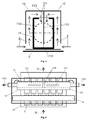
- the suction device is preferably designed as a tube-in-tube construction. It thus has an inner tube and an outer tube.
- the tube cross sections can be identical or different.
- inner and outer tubes have a round cross-section.
- the cross sections are rectangular or approximately rectangular with rounded corners.
- the preparation of the tubes can also be achieved by joining individual partial shapes, such as half shells, U-plates and other sheet metal parts.
- the inner tube has an outer diameter which is smaller than the inner diameter of the outer tube.
- the pump or pumps are connected to the inner tube, preferably at its end faces.
- the inner tube has one or more suction openings, is sucked through the gas from the space between the outside of the inner tube and the inside of the outer tube.
- the intake openings are variable in their opening width. This is realized, for example, by diaphragms which are provided by at least one further tube (diaphragm tube) which bears tightly against the inner or outer wall of the inner tube and is rotatable and / or displaceable with respect thereto and which has openings which partly close the suction openings.
- the intake characteristic of the intake depending on their axial position.
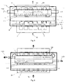
- the inner tube has a dividing wall, which divides it into two intake regions for at least one pump which sucks on the end faces. Furthermore, it is preferable to provide this partition slidably.
- the inner tube is twistable, d. H. the inner tube can be twisted about its longitudinal axis in the circumferential direction.
- the inner tube is fixed at one end, while the other end is twisted.
- the inner tube is held centrally and the two ends can be rotated.
- the central support is preferably made by a rigid partition, which connects the inner tube to the outer tube.
- the inner tube is connected via one or more partitions with the outer tube.
- the resulting inner pipe sections are individually adjustable in their orientation (axially rotatable).
- the outer tube has the suction openings through which gas is sucked from the coating chamber into the space between the outer side of the inner tube and the inner side of the outer tube.
- the suction openings of the inner tube are preferably directed away from the suction openings of the outer tube.
- the outer tube on its outside on Strömungsleitbleche that can be changed in position and orientation by moving or twisting.
- the outer tube has aperture tubes analogous to the embodiments described for the inner tube.
- the outer tube is divided into at least two independently rotatable sections in the circumferential direction. These sections are supported by partitions that connect them to the inner tube, or are arranged on holding structures that receive outside of the outer tube this and connect to the wall of the coating chamber and supported there. Furthermore, it is preferable to provide the outer tube in its entire length or sections twistable. For this purpose, the outer tube is clamped at one end and the other end is rotated relative to the first.
- a further preferred embodiment provides a central holder (by means of a cutting disc on the inner tube or by means of a holding structure) in front of which then advantageously the two ends can be rotated independently of each other.
- the twistable outer tube is clamped at both ends and twisted between them.
- the rotation can attack centrally or off-center, so that the resulting torsion sections fail asymmetrically.
- this is done by means of a device which, displaceable in its point of application in the axial direction, engages the outside of the outer tube.
- a device which, displaceable in its point of application in the axial direction, engages the outside of the outer tube.
- axis-parallel elevations are provided on the outer tube, which is engaged by a clamp or the like.
- inner and outer tube may be the same or different. They are particularly dependent on the desired variation possibilities of flow design.
- inner or outer tubes which are only changed in their orientation (also in sections) preferably made of stainless steel or aluminum alloys.
- Tordable tubes are preferably made of woven or composite materials. Carbon fiber fabrics or carbon fiber composites are used in particular here. Also suitable are steel fiber braided pipes. In principle, the substances from the prior art, which are already used in the coating plants.
- the lining or lining parts are preferably sheets, films or tapes of suitable materials or composite materials.
- the design of these parts can be net-like, fabric-like, perforated plate-like or otherwise profiled. This can extend the service life of the device and the maintenance can be significantly simplified.
- the suction device has, in a preferred embodiment, at least one diffuser, which causes a further homogenization of the sucked gas flow.
- the diffuser may extend over portions of the suction device or the entire suction device.
- the diffuser is designed as a labyrinth construction in the suction device, here in the intermediate space between the outside of the inner tube and the inner side of the outer tube.
- the labyrinth is designed so that it has a pressure loss in the axial direction of the suction device, which is much smaller than the pressure loss in the circumferential direction.
- the diffuser can be designed as an arrangement of several short axis-parallel Strömungsleitbleche. Further preferred embodiments provide a perforated or net-like axis-parallel structure which increases the pressure loss in the circumferential direction, whereby the pressure in the intermediate space between the suction openings and the diffuser structures is equalized.
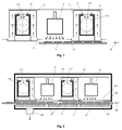
- a plurality of inner tubes are arranged in an outer tube.
- the common, superimposed opening geometry of both openings is preferably defined defined by an axial rotation of the inner tube relative to the baffle arrangement.
- a locally variable gas suction profile can also be envisaged by rotating the inner tube and / or the diaphragm tube.
- additional suction openings z. B. be arranged distributed on further angular positions and axial positions on the mantle of the inner ear. By an axial rotation of the inner ear even a more complex setting of different flow resistance and their effect on the gas flow profile is adjustable.
- the inner tube is provided with a rotary drive, a temporally variable adjustment of gas flow profiles of this gas suction can also be achieved.
- the suction device is preferably arranged adjacent to a coating device in the coating chamber. In this way it is advantageously ensured that coating gas which does not reach the substrate is sucked off as completely as possible and does not precipitate uncontrollably. In this way, it is advantageous to increase the service life of the system between two cleaning cycles.
- the gas suction is used so that it is arranged directly adjacent to a coating device, wherein between the coating device and the substrate, a diaphragm is arranged with a diaphragm opening.
- This panel ensures that only a designated area of the substrate is reached directly from the gas of the coating apparatus. So z. B. a portion of the substrate support (if one is used) are removed from a direct coating. The excess gas is advantageously removed to a large extent by the gas extraction from the treatment chamber before it can pass through the aperture.
- the coating device used is preferably at least one magnetron that extends over the entire width of the substrate in a rod-shaped construction. Further preferred embodiments provide a plurality of magnetrons in series arrangement, which form the rod-shaped design.
- gas suction device preferably in further plasma processing plants. These may be surface processes such as cleaning, activating, functionalizing, plasma etching and coating. Scalable plasma sources are predominantly used. These can be either linear or area scalable. The working pressure range is about 10 -2 mbar up to a few mbar. The total gas flow can be between a few sccm (standard cubic centimeters per minute) and a few thousand sccm.
- the processing areas in the plasma processing plants can also use different processing methods. So z. B. Pre-cleaning and coating.
- reactive processes can be separated from non-reactive processes. Also, the separation of different dopant regions, etc. is possible.
- a defined process environment is to be created overall. At the same time, the defined gas flow influencing in preferred embodiments should also enable gas separation.
- the pressure range is at some 10 -4 mbar up to approximately 10 -2 mbar.
- the total gas flow is usually much lower than in plasma processing plants.
- the gas suction device according to the invention can be used to operate different coating regions without mechanical separation, such as partitions or locks.
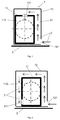
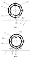
- the embodiment relates to that in the figure Fig. 1 illustrated embodiment.
- the cross section of the inner tube (11) is rectangular and has dimensions of 8 cm x 14 cm.
- the outer tube is in the space (21) about 15 mm away from the inner tube.
- the opening width of the suction opening (121) of the outer tube is 12 mm.
- the suction opening (121) extends over the entire length of the outer tube (12).
- the inner tube is made of a standard rectangular tube made of stainless steel sheet. Its wall thickness is about 2mm.
- the outer tube (12) consists of stainless steel sheet (sheet thickness approx. 1 mm). Approximately centrally to the length of the inner tube (11) has two juxtaposed suction ports (111) are present. An intermediate plate, not shown, separates the inner tube (11) radially, in the middle of its overall length, into two separately pumped tube sections.
- the distance between the intake openings is about 60mm.
- the opening width of each suction opening (111) is about 30 mm and its length 250mm.Die total length of the device is about 100cm.
- a negative pressure of 0.1 mbar to 0.5 mbar is produced in the interior of the inner tube (11) via the connection opening (112) of the vacuum pump.
- the extracted volume flow is 1000 sccm - 2000 sccm (sccm - standard cubic centimeter). Due to the special design and arrangement of the intake openings (111), a gas flow (2) which is slightly reinforced towards the middle is achieved.
- the essential features of the figures described can also be combined with one another.
- several identical or different gas extraction devices according to the invention can be used. It can also be several processing chambers successively merged into a more complex processing system.
- the different possible functions of the suction device according to the invention such as a defined gas extraction, a gas flow profile adaptation or a gas separation, can be implemented individually or in combination.
Landscapes
- Chemical & Material Sciences (AREA)
- Chemical Kinetics & Catalysis (AREA)
- Engineering & Computer Science (AREA)
- Materials Engineering (AREA)
- Mechanical Engineering (AREA)
- Metallurgy (AREA)
- Organic Chemistry (AREA)
- General Chemical & Material Sciences (AREA)
- Chemical Vapour Deposition (AREA)
- Physical Vapour Deposition (AREA)
Claims (15)
- Dispositif destiné à déplacer des gaz dans des installations de revêtement sous vide, comportant- au moins une chambre de revêtement avec au moins une zone de revêtement,- un dispositif de transport pour transporter des substrats plans dans une direction de transport dans la chambre de revêtement et pour maintenir le substrat dans cette dernière,- au moins un dispositif de revêtement par zone de revêtement, qui sépare de la matière de revêtement gazeuse, la longueur du dispositif de revêtement correspondant au moins à la largeur du substrat,- au moins un dispositif d'aspiration par zone de revêtement, le dispositif d'aspirationcaractérisé en ce que∘ s'étendant sensiblement à la parallèle du dispositif de revêtement et présentant au moins la longueur de celui-ci,∘ étant raccordé au moins sur une pompe qui est apte à générer à l'intérieur du dispositif d'aspiration une dépression par rapport à la pression intérieure de la chambre de revêtement,- l'au moins une pompe est raccordée sur le dispositif d'aspiration dans le prolongement axial de celui-ci,- le dispositif d'aspiration comporte un ou plusieurs orifices d'aspiration,- le dispositif d'aspiration comporte au moins deux zones axiales, dont les caractéristiques d'aspiration sont réglables de manière largement séparée l'une de l'autre.
- Dispositif selon la revendication 1, caractérisé en ce qu'à l'intérieur du dispositif d'aspiration est prévu au moins un système de diffuseur.
- Dispositif selon la revendication 2, caractérisé en ce que le système de diffuseur est un labyrinthe qui est conçu de sorte à présenter en direction linéaire du dispositif d'aspiration une perte de pression qui est très nettement inférieure à la perte de pression en direction périphérique.
- Dispositif selon la revendication 3, caractérisé en ce que le labyrinthe est formé en ce qu'à l'intérieur du dispositif d'aspiration est placé un tube intérieur auquel est raccordée l'au moins une pompe et qui le long de son extension longitudinale comporte un ou plusieurs orifices d'imbibition qui sont dirigés en s'éloignant des orifices d'aspiration.
- Dispositif selon la revendication 4, caractérisé en ce que les orifices d'imbibition ont une largeur d'ouverture variable.
- Dispositif selon la revendication 4, caractérisé en ce que le tube intérieur peut être tordu le long de toute sa longueur.
- Dispositif selon la revendication 6, caractérisé en ce que sur au moins un endroit, le tube intérieur est relié de manière rigide au moyen d'une paroi intermédiaire avec le tube extérieur et les tronçons de tube intérieur qui en résultent peuvent être tordus en direction périphérique, indépendamment les uns des autres.
- Dispositif selon la revendication 3, caractérisé en ce que le labyrinthe est formé en ce qu'à l'intérieur du dispositif d'aspiration est placé un tube intérieur, le tube intérieur est divisé par une paroi de séparation et l'aspiration s'effectue par des pompes placées chaque fois sur une extrémité du tube intérieur.
- Dispositif selon la revendication 8, caractérisé en ce que la paroi de séparation est placée approximativement au centre et/ou déplaçable en direction axiale.
- Dispositif selon la revendication 8, caractérisé en ce que la paroi de séparation est placée de manière stationnaire en direction axiale et de ce fait, le tube intérieur est divisé en deux tronçons de tube intérieur.
- Dispositif selon la revendication 10, caractérisé en ce que les tronçons de tube intérieur peuvent se tourner séparément l'un de l'autre autour de leur axe longitudinal.
- Dispositif selon la revendication 10, caractérisé en ce que les tronçons de tube intérieur peuvent se tordre et se tourner indépendamment l'un de l'autre en direction périphérique.
- Dispositif selon l'une quelconque des revendications précédentes, caractérisé en ce que sur sa face extérieure, le dispositif d'aspiration comporte des tôles de guidage d'écoulement, qui sont stationnaires ou déplaçables en direction axiale sur le dispositif d'aspiration.
- Dispositif selon la revendication 4, caractérisé en ce que sur sa face extérieure, le tube intérieur comporte des tôles de guidage d'écoulement qui influencent l'écoulement s'écoulant à travers les orifices d'imbibition et qui sont stationnaires ou déplaçables en direction axiale sur le tubé intérieur.
- Dispositif selon l'une quelconque des revendications précédentes, caractérisé en ce que le tube intérieur est muni d'au moins un entraînement en rotation qui fait tourner le tube intérieur complètement ou par tronçons autour de son axe longitudinal, au cours d'un traitement des substrats.
Applications Claiming Priority (2)
| Application Number | Priority Date | Filing Date | Title |
|---|---|---|---|
| DE102012213095.0A DE102012213095A1 (de) | 2012-07-25 | 2012-07-25 | Gasseparation |
| PCT/EP2013/065513 WO2014016297A1 (fr) | 2012-07-25 | 2013-07-23 | Séparation de gaz |
Publications (2)
| Publication Number | Publication Date |
|---|---|
| EP2877610A1 EP2877610A1 (fr) | 2015-06-03 |
| EP2877610B1 true EP2877610B1 (fr) | 2016-05-11 |
Family
ID=48832930
Family Applications (1)
| Application Number | Title | Priority Date | Filing Date |
|---|---|---|---|
| EP13739717.0A Active EP2877610B1 (fr) | 2012-07-25 | 2013-07-23 | Séparation de gaz |
Country Status (7)
| Country | Link |
|---|---|
| US (1) | US9556517B2 (fr) |
| EP (1) | EP2877610B1 (fr) |
| KR (1) | KR102164423B1 (fr) |
| CN (1) | CN104508177B (fr) |
| DE (1) | DE102012213095A1 (fr) |
| MY (1) | MY170266A (fr) |
| WO (1) | WO2014016297A1 (fr) |
Families Citing this family (6)
| Publication number | Priority date | Publication date | Assignee | Title |
|---|---|---|---|---|
| DE102012213095A1 (de) * | 2012-07-25 | 2014-01-30 | Roth & Rau Ag | Gasseparation |
| CN108728795B (zh) * | 2017-04-13 | 2021-06-08 | 北京北方华创微电子装备有限公司 | 一种工艺设备 |
| US20190330734A1 (en) * | 2018-04-25 | 2019-10-31 | The Board Of Trustees Of The University Of Illinois | Method of coating heat transfer components to impart superhydrophobicity |
| CN112391597B (zh) * | 2020-10-30 | 2022-12-30 | 北京七星华创集成电路装备有限公司 | 半导体工艺设备 |
| US11469072B2 (en) * | 2021-02-17 | 2022-10-11 | ICT Integrated Circuit Testing Gesellschaft für Halbleiterprüftechnik mbH | Charged particle beam apparatus, scanning electron microscope, and method of operating a charged particle beam apparatus |
| CN117604494B (zh) * | 2024-01-23 | 2024-05-17 | 楚赟精工科技(上海)有限公司 | 一种化学气相沉积设备 |
Family Cites Families (23)
| Publication number | Priority date | Publication date | Assignee | Title |
|---|---|---|---|---|
| DD214865A1 (de) | 1983-05-04 | 1984-10-24 | Fi M V Ardenne Dresden | Verfahren und einrichtung zur herstellung von schichtsystemen auf flachglas |
| US4949669A (en) * | 1988-12-20 | 1990-08-21 | Texas Instruments Incorporated | Gas flow systems in CCVD reactors |
| DE4303462C2 (de) | 1992-03-30 | 1994-03-31 | Leybold Ag | Mehrkammerbeschichtungsanlage |
| US6200389B1 (en) * | 1994-07-18 | 2001-03-13 | Silicon Valley Group Thermal Systems Llc | Single body injector and deposition chamber |
| US7515264B2 (en) * | 1999-06-15 | 2009-04-07 | Tokyo Electron Limited | Particle-measuring system and particle-measuring method |
| KR20010086971A (ko) * | 2000-03-06 | 2001-09-15 | 구자홍 | 플라즈마 중합처리장치의 급배기 시스템 |
| FR2816726B1 (fr) * | 2000-11-16 | 2006-06-23 | Air Liquide | Installation dans laquelle est realisee une operation necessitant un controle de l'atmosphere a l'interieur d'une enceinte |
| US6626997B2 (en) * | 2001-05-17 | 2003-09-30 | Nathan P. Shapiro | Continuous processing chamber |
| JP3913646B2 (ja) * | 2002-08-30 | 2007-05-09 | 東京エレクトロン株式会社 | 基板処理装置 |
| US7537662B2 (en) * | 2003-04-29 | 2009-05-26 | Asm International N.V. | Method and apparatus for depositing thin films on a surface |
| DE102005045582B3 (de) * | 2005-09-23 | 2007-03-29 | Fraunhofer-Gesellschaft zur Förderung der angewandten Forschung e.V. | Vorrichtung und Verfahren zur kontinuierlichen Gasphasenabscheidung unter Atmosphärendruck und deren Verwendung |
| DE112006002804A5 (de) | 2005-11-21 | 2008-09-04 | Von Ardenne Anlagentechnik Gmbh | Trenneinrichtung für Prozesskammern von Vakuumbeschichtungsanlagen und Vakuumbeschichtungsanlage |
| CN101589171A (zh) * | 2006-03-03 | 2009-11-25 | 普拉萨德·盖德吉尔 | 用于大面积多层原子层化学气相处理薄膜的装置和方法 |
| US20070256934A1 (en) * | 2006-05-08 | 2007-11-08 | Perata Michael R | Apparatus and Method for Coating Substrates With Approximate Process Isolation |
| DE102008026001B4 (de) * | 2007-09-04 | 2012-02-16 | Von Ardenne Anlagentechnik Gmbh | Verfahren und Vorrichtung zur Erzeugung und Bearbeitung von Schichten auf Substraten unter definierter Prozessatmosphäre und Heizelement |
| JP5391190B2 (ja) * | 2008-03-26 | 2014-01-15 | 東京エレクトロン株式会社 | 処理チャンバの排気ガス流量の制御方法及び処理装置 |
| DE102010028734B4 (de) | 2009-05-08 | 2021-07-22 | VON ARDENNE Asset GmbH & Co. KG | Gasseparationsanordnung einer Vakuumbeschichtungsanlage |
| EP2281921A1 (fr) * | 2009-07-30 | 2011-02-09 | Nederlandse Organisatie voor toegepast -natuurwetenschappelijk onderzoek TNO | Procédé et appareil pour le dépôt de couches atomiques |
| EP2481830A1 (fr) * | 2011-01-31 | 2012-08-01 | Nederlandse Organisatie voor toegepast -natuurwetenschappelijk onderzoek TNO | Appareil pour le dépôt de couches atomiques |
| EP2481832A1 (fr) * | 2011-01-31 | 2012-08-01 | Nederlandse Organisatie voor toegepast -natuurwetenschappelijk onderzoek TNO | Appareil pour le dépôt de couches atomiques |
| EP2481833A1 (fr) * | 2011-01-31 | 2012-08-01 | Nederlandse Organisatie voor toegepast -natuurwetenschappelijk onderzoek TNO | Appareil pour le dépôt de couches atomiques |
| DE102012213095A1 (de) * | 2012-07-25 | 2014-01-30 | Roth & Rau Ag | Gasseparation |
| JP6334880B2 (ja) * | 2013-10-03 | 2018-05-30 | Jswアフティ株式会社 | 原子層堆積装置および原子層堆積方法 |
-
2012
- 2012-07-25 DE DE102012213095.0A patent/DE102012213095A1/de not_active Withdrawn
-
2013
- 2013-07-23 KR KR1020157004878A patent/KR102164423B1/ko not_active Expired - Fee Related
- 2013-07-23 EP EP13739717.0A patent/EP2877610B1/fr active Active
- 2013-07-23 MY MYPI2015700156A patent/MY170266A/en unknown
- 2013-07-23 WO PCT/EP2013/065513 patent/WO2014016297A1/fr not_active Ceased
- 2013-07-23 US US14/416,063 patent/US9556517B2/en not_active Expired - Fee Related
- 2013-07-23 CN CN201380039230.2A patent/CN104508177B/zh not_active Expired - Fee Related
Also Published As
| Publication number | Publication date |
|---|---|
| CN104508177A (zh) | 2015-04-08 |
| WO2014016297A1 (fr) | 2014-01-30 |
| KR102164423B1 (ko) | 2020-10-12 |
| US9556517B2 (en) | 2017-01-31 |
| MY170266A (en) | 2019-07-15 |
| KR20150036764A (ko) | 2015-04-07 |
| DE102012213095A1 (de) | 2014-01-30 |
| DE102012213095A9 (de) | 2014-04-10 |
| CN104508177B (zh) | 2016-12-14 |
| EP2877610A1 (fr) | 2015-06-03 |
| US20150225847A1 (en) | 2015-08-13 |
Similar Documents
| Publication | Publication Date | Title |
|---|---|---|
| EP2877610B1 (fr) | Séparation de gaz | |
| DE4341173B4 (de) | Vorrichtung und Verfahren zur Abscheidung unterschiedlicher Materialien auf einem Substrat | |
| DE112013006223B4 (de) | Substratbearbeitungsgerät | |
| DE102014116696B4 (de) | Vakuumkammer und Verfahren zum Betreiben einer Vakuumprozessieranlage | |
| DE1521520B1 (de) | Vorrichtung zur kontinuierlichen Herstellung einer duennen Folie,insbesondere aus Metall,durch Vakuumaufdampfen | |
| DE4235953A1 (de) | Sputterquelle | |
| DE102008026001B4 (de) | Verfahren und Vorrichtung zur Erzeugung und Bearbeitung von Schichten auf Substraten unter definierter Prozessatmosphäre und Heizelement | |
| EP3610050B2 (fr) | Procédés de revêtement permettant le dépôt réactif en phase vapeur sous vide sur un substrat | |
| EP1840936A1 (fr) | Chambre de pulvérisation cathodique pour le revêtement d'un substrat | |
| DE102010022277A1 (de) | Vorrichtung und Verfahren zur Reaktivgastrennung in in-line-Beschichtungsanlagen | |
| EP1884576B1 (fr) | Dispositif destiné au revêtement par plasma de composants longitudinaux et cylindriques | |
| DE102013108994A1 (de) | Verfahren und Anordnung zur Einstellung homogener Schichteigenschaften beim Magnetronsputtern | |
| WO2001040534A2 (fr) | Dispositif et procede pour le revetement d'objets a haute temperature | |
| DE202014101468U1 (de) | Prozessiervorrichtung, Beschichtungsvorrichtung und Prozesskammer-Anordnung | |
| DE102014109265A1 (de) | Vakuumbehandlungsanlage | |
| DE102014107623B4 (de) | Prozessieranlage | |
| DE102023105638A1 (de) | Kammerdeckel und Vakuumkammer | |
| DE102013108405B4 (de) | Durchlauf-Substratbehandlungsanlage und Reinigungsverfahren | |
| EP2041434B1 (fr) | Pompe getter, et installation d'application de revêtement sous vide équipée de cette pompe getter | |
| DE102012110287B4 (de) | Substratbehandlungsanlage und Verfahren zur Druckminderung | |
| DE102015107297A1 (de) | Prozessieranordnung | |
| DE102017130943A1 (de) | Vakuumkammeranordnung | |
| DE102019132526B4 (de) | Beschichtungsmaschine | |
| WO2013131508A1 (fr) | Dispositif et procédé de revêtement par plasma d'éléments structuraux cylindriques de forme allongée | |
| WO2007017175A2 (fr) | Metallisation sous vide avec evacuation de condensat |
Legal Events
| Date | Code | Title | Description |
|---|---|---|---|
| PUAI | Public reference made under article 153(3) epc to a published international application that has entered the european phase |
Free format text: ORIGINAL CODE: 0009012 |
|
| 17P | Request for examination filed |
Effective date: 20150223 |
|
| AK | Designated contracting states |
Kind code of ref document: A1 Designated state(s): AL AT BE BG CH CY CZ DE DK EE ES FI FR GB GR HR HU IE IS IT LI LT LU LV MC MK MT NL NO PL PT RO RS SE SI SK SM TR |
|
| AX | Request for extension of the european patent |
Extension state: BA ME |
|
| RIN1 | Information on inventor provided before grant (corrected) |
Inventor name: LOEWEL, OLIVER Inventor name: MAI, JOACHIM Inventor name: DECKER, DANIEL Inventor name: HELBIG, STEFAN |
|
| DAX | Request for extension of the european patent (deleted) | ||
| RAP1 | Party data changed (applicant data changed or rights of an application transferred) |
Owner name: MEYER BURGER (GERMANY) AG |
|
| GRAP | Despatch of communication of intention to grant a patent |
Free format text: ORIGINAL CODE: EPIDOSNIGR1 |
|
| INTG | Intention to grant announced |
Effective date: 20151217 |
|
| GRAS | Grant fee paid |
Free format text: ORIGINAL CODE: EPIDOSNIGR3 |
|
| GRAA | (expected) grant |
Free format text: ORIGINAL CODE: 0009210 |
|
| AK | Designated contracting states |
Kind code of ref document: B1 Designated state(s): AL AT BE BG CH CY CZ DE DK EE ES FI FR GB GR HR HU IE IS IT LI LT LU LV MC MK MT NL NO PL PT RO RS SE SI SK SM TR |
|
| REG | Reference to a national code |
Ref country code: GB Ref legal event code: FG4D Free format text: NOT ENGLISH |
|
| REG | Reference to a national code |
Ref country code: CH Ref legal event code: EP |
|
| REG | Reference to a national code |
Ref country code: AT Ref legal event code: REF Ref document number: 798738 Country of ref document: AT Kind code of ref document: T Effective date: 20160515 |
|
| REG | Reference to a national code |
Ref country code: IE Ref legal event code: FG4D Free format text: LANGUAGE OF EP DOCUMENT: GERMAN |
|
| REG | Reference to a national code |
Ref country code: DE Ref legal event code: R096 Ref document number: 502013002981 Country of ref document: DE |
|
| REG | Reference to a national code |
Ref country code: CH Ref legal event code: NV Representative=s name: FREI PATENTANWALTSBUERO AG, CH |
|
| REG | Reference to a national code |
Ref country code: LT Ref legal event code: MG4D |
|
| REG | Reference to a national code |
Ref country code: NL Ref legal event code: MP Effective date: 20160511 |
|
| PG25 | Lapsed in a contracting state [announced via postgrant information from national office to epo] |
Ref country code: NL Free format text: LAPSE BECAUSE OF FAILURE TO SUBMIT A TRANSLATION OF THE DESCRIPTION OR TO PAY THE FEE WITHIN THE PRESCRIBED TIME-LIMIT Effective date: 20160511 Ref country code: NO Free format text: LAPSE BECAUSE OF FAILURE TO SUBMIT A TRANSLATION OF THE DESCRIPTION OR TO PAY THE FEE WITHIN THE PRESCRIBED TIME-LIMIT Effective date: 20160811 Ref country code: LT Free format text: LAPSE BECAUSE OF FAILURE TO SUBMIT A TRANSLATION OF THE DESCRIPTION OR TO PAY THE FEE WITHIN THE PRESCRIBED TIME-LIMIT Effective date: 20160511 Ref country code: FI Free format text: LAPSE BECAUSE OF FAILURE TO SUBMIT A TRANSLATION OF THE DESCRIPTION OR TO PAY THE FEE WITHIN THE PRESCRIBED TIME-LIMIT Effective date: 20160511 |
|
| PG25 | Lapsed in a contracting state [announced via postgrant information from national office to epo] |
Ref country code: HR Free format text: LAPSE BECAUSE OF FAILURE TO SUBMIT A TRANSLATION OF THE DESCRIPTION OR TO PAY THE FEE WITHIN THE PRESCRIBED TIME-LIMIT Effective date: 20160511 Ref country code: SE Free format text: LAPSE BECAUSE OF FAILURE TO SUBMIT A TRANSLATION OF THE DESCRIPTION OR TO PAY THE FEE WITHIN THE PRESCRIBED TIME-LIMIT Effective date: 20160511 Ref country code: LV Free format text: LAPSE BECAUSE OF FAILURE TO SUBMIT A TRANSLATION OF THE DESCRIPTION OR TO PAY THE FEE WITHIN THE PRESCRIBED TIME-LIMIT Effective date: 20160511 Ref country code: ES Free format text: LAPSE BECAUSE OF FAILURE TO SUBMIT A TRANSLATION OF THE DESCRIPTION OR TO PAY THE FEE WITHIN THE PRESCRIBED TIME-LIMIT Effective date: 20160511 Ref country code: RS Free format text: LAPSE BECAUSE OF FAILURE TO SUBMIT A TRANSLATION OF THE DESCRIPTION OR TO PAY THE FEE WITHIN THE PRESCRIBED TIME-LIMIT Effective date: 20160511 Ref country code: GR Free format text: LAPSE BECAUSE OF FAILURE TO SUBMIT A TRANSLATION OF THE DESCRIPTION OR TO PAY THE FEE WITHIN THE PRESCRIBED TIME-LIMIT Effective date: 20160812 Ref country code: PT Free format text: LAPSE BECAUSE OF FAILURE TO SUBMIT A TRANSLATION OF THE DESCRIPTION OR TO PAY THE FEE WITHIN THE PRESCRIBED TIME-LIMIT Effective date: 20160912 |
|
| PG25 | Lapsed in a contracting state [announced via postgrant information from national office to epo] |
Ref country code: BE Free format text: LAPSE BECAUSE OF NON-PAYMENT OF DUE FEES Effective date: 20160731 Ref country code: IT Free format text: LAPSE BECAUSE OF FAILURE TO SUBMIT A TRANSLATION OF THE DESCRIPTION OR TO PAY THE FEE WITHIN THE PRESCRIBED TIME-LIMIT Effective date: 20160511 |
|
| PG25 | Lapsed in a contracting state [announced via postgrant information from national office to epo] |
Ref country code: CZ Free format text: LAPSE BECAUSE OF FAILURE TO SUBMIT A TRANSLATION OF THE DESCRIPTION OR TO PAY THE FEE WITHIN THE PRESCRIBED TIME-LIMIT Effective date: 20160511 Ref country code: SK Free format text: LAPSE BECAUSE OF FAILURE TO SUBMIT A TRANSLATION OF THE DESCRIPTION OR TO PAY THE FEE WITHIN THE PRESCRIBED TIME-LIMIT Effective date: 20160511 Ref country code: DK Free format text: LAPSE BECAUSE OF FAILURE TO SUBMIT A TRANSLATION OF THE DESCRIPTION OR TO PAY THE FEE WITHIN THE PRESCRIBED TIME-LIMIT Effective date: 20160511 Ref country code: RO Free format text: LAPSE BECAUSE OF FAILURE TO SUBMIT A TRANSLATION OF THE DESCRIPTION OR TO PAY THE FEE WITHIN THE PRESCRIBED TIME-LIMIT Effective date: 20160511 Ref country code: EE Free format text: LAPSE BECAUSE OF FAILURE TO SUBMIT A TRANSLATION OF THE DESCRIPTION OR TO PAY THE FEE WITHIN THE PRESCRIBED TIME-LIMIT Effective date: 20160511 |
|
| REG | Reference to a national code |
Ref country code: DE Ref legal event code: R097 Ref document number: 502013002981 Country of ref document: DE |
|
| PG25 | Lapsed in a contracting state [announced via postgrant information from national office to epo] |
Ref country code: SM Free format text: LAPSE BECAUSE OF FAILURE TO SUBMIT A TRANSLATION OF THE DESCRIPTION OR TO PAY THE FEE WITHIN THE PRESCRIBED TIME-LIMIT Effective date: 20160511 Ref country code: PL Free format text: LAPSE BECAUSE OF FAILURE TO SUBMIT A TRANSLATION OF THE DESCRIPTION OR TO PAY THE FEE WITHIN THE PRESCRIBED TIME-LIMIT Effective date: 20160511 |
|
| PLBE | No opposition filed within time limit |
Free format text: ORIGINAL CODE: 0009261 |
|
| STAA | Information on the status of an ep patent application or granted ep patent |
Free format text: STATUS: NO OPPOSITION FILED WITHIN TIME LIMIT |
|
| PG25 | Lapsed in a contracting state [announced via postgrant information from national office to epo] |
Ref country code: MC Free format text: LAPSE BECAUSE OF FAILURE TO SUBMIT A TRANSLATION OF THE DESCRIPTION OR TO PAY THE FEE WITHIN THE PRESCRIBED TIME-LIMIT Effective date: 20160511 |
|
| 26N | No opposition filed |
Effective date: 20170214 |
|
| PG25 | Lapsed in a contracting state [announced via postgrant information from national office to epo] |
Ref country code: FR Free format text: LAPSE BECAUSE OF NON-PAYMENT OF DUE FEES Effective date: 20160801 |
|
| REG | Reference to a national code |
Ref country code: FR Ref legal event code: ST Effective date: 20170331 |
|
| REG | Reference to a national code |
Ref country code: IE Ref legal event code: MM4A |
|
| PG25 | Lapsed in a contracting state [announced via postgrant information from national office to epo] |
Ref country code: SI Free format text: LAPSE BECAUSE OF FAILURE TO SUBMIT A TRANSLATION OF THE DESCRIPTION OR TO PAY THE FEE WITHIN THE PRESCRIBED TIME-LIMIT Effective date: 20160511 |
|
| PG25 | Lapsed in a contracting state [announced via postgrant information from national office to epo] |
Ref country code: IE Free format text: LAPSE BECAUSE OF NON-PAYMENT OF DUE FEES Effective date: 20160723 |
|
| PG25 | Lapsed in a contracting state [announced via postgrant information from national office to epo] |
Ref country code: LU Free format text: LAPSE BECAUSE OF NON-PAYMENT OF DUE FEES Effective date: 20160723 |
|
| GBPC | Gb: european patent ceased through non-payment of renewal fee |
Effective date: 20170723 |
|
| PG25 | Lapsed in a contracting state [announced via postgrant information from national office to epo] |
Ref country code: GB Free format text: LAPSE BECAUSE OF NON-PAYMENT OF DUE FEES Effective date: 20170723 |
|
| PG25 | Lapsed in a contracting state [announced via postgrant information from national office to epo] |
Ref country code: HU Free format text: LAPSE BECAUSE OF FAILURE TO SUBMIT A TRANSLATION OF THE DESCRIPTION OR TO PAY THE FEE WITHIN THE PRESCRIBED TIME-LIMIT; INVALID AB INITIO Effective date: 20130723 |
|
| PG25 | Lapsed in a contracting state [announced via postgrant information from national office to epo] |
Ref country code: MK Free format text: LAPSE BECAUSE OF FAILURE TO SUBMIT A TRANSLATION OF THE DESCRIPTION OR TO PAY THE FEE WITHIN THE PRESCRIBED TIME-LIMIT Effective date: 20160511 Ref country code: IS Free format text: LAPSE BECAUSE OF FAILURE TO SUBMIT A TRANSLATION OF THE DESCRIPTION OR TO PAY THE FEE WITHIN THE PRESCRIBED TIME-LIMIT Effective date: 20160511 Ref country code: CY Free format text: LAPSE BECAUSE OF FAILURE TO SUBMIT A TRANSLATION OF THE DESCRIPTION OR TO PAY THE FEE WITHIN THE PRESCRIBED TIME-LIMIT Effective date: 20160511 Ref country code: MT Free format text: LAPSE BECAUSE OF FAILURE TO SUBMIT A TRANSLATION OF THE DESCRIPTION OR TO PAY THE FEE WITHIN THE PRESCRIBED TIME-LIMIT Effective date: 20160511 |
|
| PG25 | Lapsed in a contracting state [announced via postgrant information from national office to epo] |
Ref country code: BG Free format text: LAPSE BECAUSE OF FAILURE TO SUBMIT A TRANSLATION OF THE DESCRIPTION OR TO PAY THE FEE WITHIN THE PRESCRIBED TIME-LIMIT Effective date: 20160511 |
|
| PG25 | Lapsed in a contracting state [announced via postgrant information from national office to epo] |
Ref country code: TR Free format text: LAPSE BECAUSE OF FAILURE TO SUBMIT A TRANSLATION OF THE DESCRIPTION OR TO PAY THE FEE WITHIN THE PRESCRIBED TIME-LIMIT Effective date: 20160511 Ref country code: AL Free format text: LAPSE BECAUSE OF FAILURE TO SUBMIT A TRANSLATION OF THE DESCRIPTION OR TO PAY THE FEE WITHIN THE PRESCRIBED TIME-LIMIT Effective date: 20160511 |
|
| REG | Reference to a national code |
Ref country code: CH Ref legal event code: PCAR Free format text: NEW ADDRESS: POSTFACH, 8032 ZUERICH (CH) |
|
| REG | Reference to a national code |
Ref country code: AT Ref legal event code: MM01 Ref document number: 798738 Country of ref document: AT Kind code of ref document: T Effective date: 20180723 |
|
| PG25 | Lapsed in a contracting state [announced via postgrant information from national office to epo] |
Ref country code: AT Free format text: LAPSE BECAUSE OF NON-PAYMENT OF DUE FEES Effective date: 20180723 |
|
| PGFP | Annual fee paid to national office [announced via postgrant information from national office to epo] |
Ref country code: DE Payment date: 20220727 Year of fee payment: 10 |
|
| PGFP | Annual fee paid to national office [announced via postgrant information from national office to epo] |
Ref country code: CH Payment date: 20220726 Year of fee payment: 10 |
|
| REG | Reference to a national code |
Ref country code: DE Ref legal event code: R119 Ref document number: 502013002981 Country of ref document: DE |
|
| REG | Reference to a national code |
Ref country code: CH Ref legal event code: PL |
|
| PG25 | Lapsed in a contracting state [announced via postgrant information from national office to epo] |
Ref country code: DE Free format text: LAPSE BECAUSE OF NON-PAYMENT OF DUE FEES Effective date: 20240201 Ref country code: CH Free format text: LAPSE BECAUSE OF NON-PAYMENT OF DUE FEES Effective date: 20230731 |