EP2877657B1 - Zuhaltung für eine zugangsschutzvorrichtung mit einer hilfsentriegelung - Google Patents
Zuhaltung für eine zugangsschutzvorrichtung mit einer hilfsentriegelung Download PDFInfo
- Publication number
- EP2877657B1 EP2877657B1 EP13739461.5A EP13739461A EP2877657B1 EP 2877657 B1 EP2877657 B1 EP 2877657B1 EP 13739461 A EP13739461 A EP 13739461A EP 2877657 B1 EP2877657 B1 EP 2877657B1
- Authority
- EP
- European Patent Office
- Prior art keywords
- locking
- transmission element
- handle
- transmission
- axis
- Prior art date
- Legal status (The legal status is an assumption and is not a legal conclusion. Google has not performed a legal analysis and makes no representation as to the accuracy of the status listed.)
- Active
Links
Images

Classifications
-
- E—FIXED CONSTRUCTIONS
- E05—LOCKS; KEYS; WINDOW OR DOOR FITTINGS; SAFES
- E05B—LOCKS; ACCESSORIES THEREFOR; HANDCUFFS
- E05B47/00—Operating or controlling locks or other fastening devices by electric or magnetic means
- E05B47/02—Movement of the bolt by electromagnetic means; Adaptation of locks, latches, or parts thereof, for movement of the bolt by electromagnetic means
- E05B47/026—Movement of the bolt by electromagnetic means; Adaptation of locks, latches, or parts thereof, for movement of the bolt by electromagnetic means the bolt moving rectilinearly
-
- F—MECHANICAL ENGINEERING; LIGHTING; HEATING; WEAPONS; BLASTING
- F16—ENGINEERING ELEMENTS AND UNITS; GENERAL MEASURES FOR PRODUCING AND MAINTAINING EFFECTIVE FUNCTIONING OF MACHINES OR INSTALLATIONS; THERMAL INSULATION IN GENERAL
- F16P—SAFETY DEVICES IN GENERAL; SAFETY DEVICES FOR PRESSES
- F16P3/00—Safety devices acting in conjunction with the control or operation of a machine; Control arrangements requiring the simultaneous use of two or more parts of the body
- F16P3/08—Safety devices acting in conjunction with the control or operation of a machine; Control arrangements requiring the simultaneous use of two or more parts of the body in connection with the locking of doors, covers, guards, or like members giving access to moving machine parts
-
- E—FIXED CONSTRUCTIONS
- E05—LOCKS; KEYS; WINDOW OR DOOR FITTINGS; SAFES
- E05B—LOCKS; ACCESSORIES THEREFOR; HANDCUFFS
- E05B15/00—Other details of locks; Parts for engagement by bolts of fastening devices
- E05B15/10—Bolts of locks or night latches
- E05B15/101—Spring-retracted bolts
-
- E—FIXED CONSTRUCTIONS
- E05—LOCKS; KEYS; WINDOW OR DOOR FITTINGS; SAFES
- E05B—LOCKS; ACCESSORIES THEREFOR; HANDCUFFS
- E05B47/00—Operating or controlling locks or other fastening devices by electric or magnetic means
- E05B47/0001—Operating or controlling locks or other fastening devices by electric or magnetic means with electric actuators; Constructional features thereof
- E05B2047/0014—Constructional features of actuators or power transmissions therefor
- E05B2047/0018—Details of actuator transmissions
- E05B2047/002—Geared transmissions
-
- E—FIXED CONSTRUCTIONS
- E05—LOCKS; KEYS; WINDOW OR DOOR FITTINGS; SAFES
- E05B—LOCKS; ACCESSORIES THEREFOR; HANDCUFFS
- E05B47/00—Operating or controlling locks or other fastening devices by electric or magnetic means
- E05B47/0001—Operating or controlling locks or other fastening devices by electric or magnetic means with electric actuators; Constructional features thereof
- E05B2047/0014—Constructional features of actuators or power transmissions therefor
- E05B2047/0018—Details of actuator transmissions
- E05B2047/0026—Clutches, couplings or braking arrangements
-
- E—FIXED CONSTRUCTIONS
- E05—LOCKS; KEYS; WINDOW OR DOOR FITTINGS; SAFES
- E05B—LOCKS; ACCESSORIES THEREFOR; HANDCUFFS
- E05B47/00—Operating or controlling locks or other fastening devices by electric or magnetic means
- E05B2047/0084—Key or electric means; Emergency release
- E05B2047/0086—Emergency release, e.g. key or electromagnet
-
- E—FIXED CONSTRUCTIONS
- E05—LOCKS; KEYS; WINDOW OR DOOR FITTINGS; SAFES
- E05B—LOCKS; ACCESSORIES THEREFOR; HANDCUFFS
- E05B47/00—Operating or controlling locks or other fastening devices by electric or magnetic means
- E05B47/0001—Operating or controlling locks or other fastening devices by electric or magnetic means with electric actuators; Constructional features thereof
- E05B47/0012—Operating or controlling locks or other fastening devices by electric or magnetic means with electric actuators; Constructional features thereof with rotary electromotors
Definitions
- the invention relates to a tumbler for an access protection device of a closable space area of a mechanical system, with a blocking element which is movable within a housing by means of a drive between a locking position and an unlocking position, a transmission element which is arranged between the drive and the blocking element, and a Auxiliary release with which a movement of the locking element between the positions can be effected independently of the drive.
- tumblers are known as part of an access control device for a lockable space area of a machine installation.
- the systems may be, for example, machines or components such as robots for manufacturing, treating or Machining of workpieces as well as to trade chemical plants or the like.
- a tumbler can be arranged as a fixed part between a door, flap, cover or the like which closes the room area, as a movable part and an opposite, adjacent, fixed wall or wall, for example a boundary of the protected area.
- the optionally at least one door or flap which can be opened or closed by pivoting or sliding, can be locked by the tumbler by a locking element, in particular ram or bolt of the tumbler, which is arranged for example on the fixed part, in a recess of the movable Part can retract for locking / locking.
- a locking element in particular ram or bolt of the tumbler, which is arranged for example on the fixed part, in a recess of the movable Part can retract for locking / locking.
- a tumbler of the above type which additionally has an auxiliary release, in which the transmission element is arranged movable relative to the locking element and unlocking the tumbler is additionally possible by moving the locking element independent of the drive by a manual pulling the locking element from the locking position ,
- the blocking element protrudes from the housing opening of the tumbler and has a handle which allows easier pulling by the user.
- a tumbler with a locking element which is movable within a housing by means of a drive between a locking position and an unlocking position.
- a transmission element is arranged between the drive and the blocking element.
- FR 2 635 553 A1 From the FR 2 635 553 A1 is also a tumbler with a blocking element and a transmission element is known, which is arranged between the drive and the blocking element. By actuating the auxiliary release, the transmission element can be moved.
- a tumbler with a blocking element and a transmission element which can be brought into operative connection with a worm of an engine by means of an auxiliary release.
- the transmission element is rotatably attached to the housing of the tumbler and can not be detached from the locking element.
- Object of the present invention is to develop a tumbler of the type mentioned, in which the ease of use, based on the operation of the auxiliary release, further improved, at the same time a compact design of the improved tumbler is achieved.
- the essence of the invention here is that the blocking element does not have to be contacted directly by the user in order to be able to move the blocking element out of the locking position into the unlocking position and vice versa.
- the transmission element according to the invention is movable between the coupling position and the Entkoppelwolf, wherein in the coupling position of the transmission element, the locking element can not be brought out of its locking position, except that the drive is activated and ensures movement of the locking element in the unlocked position. This means that the blocking element is blocked or locked in the locking position, as long as the transmission element assumes the coupling position.
- the blocking element can be moved only via the drive from the unlocking position into the locking position, wherein at the same time the transmission element assumes its coupling position within the tumbler.
- a significant advantage of this invention is that the handle for moving the locking element is further improved.
- the invention makes it possible to prevent direct access to the blocking element due to the auxiliary unlocking according to the invention, whereby in particular the manipulation security can be increased.
- the blocking element has a force transmission region on which the transmission element engages in its coupling position, the transmission element and the force transmission region having a toothing.
- the auxiliary unlocking has a handle accessible to a user in order to enable an actuation of the auxiliary unlocking, in particular that the handle has a contour into which a tool can be introduced.
- the handle may have a signal color, so that the user in the deactivated state of the drive on the one hand, the auxiliary release reliably locate or recognize.
- the handle has a corresponding contour into which, for example, a special tool can be introduced in order to bring the blocking element over a defined actuation of the auxiliary release from the locking position into the unlocking position.
- a first energy store which has energy in the locking position of the blocking element, which ensures that when the transmission element changes from the coupling position into the uncoupling position, the blocking element moves from the locking position into the unlocking position.
- the first energy storage serves as a technical means to act in the Entkoppelwolf of the transmission element in such a way on the blocking element that the blocking element can move reliably in the unlocking position.
- the first energy store may be a spring element which acts on the blocking element at a defined location. In the locking position, the spring element is tensioned and exerts a force acting in the unlocking position on the locking element. Since the transmission element in the coupling position represents a blocking function for the blocking element, which means that the blocking element is locked in the locking position by the transmission element, a change of position of the blocking element is excluded. It is only in the decoupling position of the transmission element that the force acting on the blocking element by the spring element causes the blocking element to move out of the locking position into the unlocking position.
- the drive is designed as an electric motor drive, which drives the transmission element in the activated state, which in turn is in operative connection with the locking element, whereby a corresponding movement of the locking element from the locking position to the unlocking position and vice versa achievable.
- the drive is designed as a spindle motor or worm motor whose spindle or worm can be in engagement with a component designed at least partially as a worm wheel. This component may also be connected to a shaft which drives the transmission element.
- the drive in the non-activated state to a self-locking, which causes the locking element is not from the locking position in the Unlocking position can be moved as long as the transmission element is in the coupling position.
- the transmission element can be moved linearly into its respective position along a movement axis.
- the toothing / toothings of the transmission element and / or the toothing / toothing of the blocking element can have rounded tooth flanks. It may be particularly advantageous that the tooth flanks are rounded off on all sides. A significant advantage of this geometric configuration of the tooth flanks is that the transmission element can be easily moved without significant friction losses from the coupling position or back into the coupling position. In addition, a noise minimization can be achieved by the inventive design of the tooth flanks.
- the handle is rotatable about an axis, wherein a translational movement of the locking element can be achieved via a rotation of the handle.
- the tumbler can be designed such that the axis of the handle lies in the plane of the movement axis of the transmission element.
- the axis of the handle is perpendicular to the plane of the axis of movement of the transmission element. Both embodiments allow the handle can be arranged at different locations on the housing, which in particular depends on the local conditions at which the tumbler can be arranged.
- the tumbler according to the invention may have a stop on the transmission element, on which the handle acts upon actuation of the auxiliary unlocking.
- the handle may have a cam extending in the direction of the transmission element, wherein in particular the cam is arranged eccentrically to the axis of the handle.
- the invention may include that the cam engages the abutment surface of the transmission element when the auxiliary unlocking is actuated.
- the cam which is rotated with the handle about its axis, so presses against the stop of the transmission element, so that the transmission element can be moved translationally along its axis of movement from the coupling position into the decoupling position.
- a second energy storage acts on the transmission element, which has an energy in the coupling position, which ensures that the transmission element moves back into the coupling position.
- the second energy store may be a spring element that exerts a defined force on the transfer element in the decoupling position.
- a return movement of the transmission element from the Entkoppelwolf in the coupling position due to the acting spring force of the second energy storage is advantageously blocked by the fact that the handle still has such a position, which effectively prevents the transmission element leaves its Entkoppelwolf.
- the cam assumes such a position within the housing, that the stop of the transmission element rests directly on the cam and prevents a return movement into the coupling position of the transmission element.
- a slide element is arranged between the transmission element and the handle, wherein in particular the slide element engages upon actuation of the handle on the stop of the transmission element.
- the slider element may be connected monolithically and / or in one piece with the handle. Likewise, the slider element may be a separate component to which the handle engages.
- a shaft connects the drive with the transmission element, wherein the shaft is rotatable about the axis of the transmission element.
- a bearing element may be provided on which the slide element and / or the shaft is / are mounted.
- the bearing element is located within the housing, wherein it may be monolithically and / or integrally connected to the housing in a further embodiment of the invention. While the handle is moved during actuation, there is a translational movement of the slide element, wherein the bearing element a ensures reliable movement of the slide element.
- the shaft connecting the drive to the transmission element can also be arranged on the bearing element.
- the shaft is mounted separately on a further, second bearing element within the housing, in particular even if no slide element is used within the tumbler.
- the tumbler of the invention may comprise a handle with a thread that causes a connection of the handle to the housing, wherein during the actuation of the auxiliary release the handle rotates about the axis of the housing, along the thread.
- a push button has, for example, sliding bearing and can also be in connection with a corresponding energy storage
- the tumbler according to the invention between a door closing the space, flap, cover or the like as a movable part and an opposite fixed wall, such as a boundary of the protection area, as a fixed part can be arranged.
- the tumbler can be placed on either the fixed part or the moving part.
- the tumbler is in signal communication with a controller to bring the blocking element according to the operating state of the mechanical system in the locking position or in the unlocked position. If no danger potential for persons emanates from the mechanical system, that is, if the room area can be accessed through the door or the room area can be accessed via the door, in which, for example, the control system stops the moving parts of the mechanical system, for example by a machine When the standstill monitor is signaled, the control releases the tumbler so that a person can enter the room area by opening the door. The tumbler is then released when the blocking element is in the unlocked position.
- the controller may be configured such that a commissioning of the mechanical system is prevented at an open door and / or at a locking element located in the unlocking position.
- first and / or the second energy accumulator as a spring element
- a conversion of kinetic energy of the transmission element or the blocking element into a potential energy of the first or the second spring element is possible.
- the power transmission region of the blocking element may be formed as a rack, wherein in a possible embodiment of the invention, the power transmission area and the blocking element are coupled together. It is conceivable that the power transmission area with the blocking element is firmly connected to each other or that the blocking element and the power transmission region of the blocking element form a common, monolithic component. It is conceivable that the blocking element and the power transmission area are formed of different materials. This may be due to the fact that the region of the blocking element which protrudes from the tumbler in the locking position, has different material requirements, as the power transmission area, which acts on the transmission element.
- a safety device may be provided within the tumbler, which can effectively allow the locking element during locking process can not drive on a blockage located outside of the housing, which would be connected in the worst case with material destruction within the tumbler or on the blocking element.
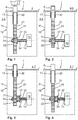
- FIG. 1 and FIG. 8 show two possible embodiments of a tumbler 10, which can be used for an access protection device 1 of a lockable space area 2 of a mechanical system 3.
- the tumbler 10 has a blocking element 20 that within a housing 11 by means of a drive 12 between a locking position 4, the in FIG. 2 and FIG. 3 is shown and an unlocking position 5, the in FIG. 1 and FIG. 4 is shown, is movable.
- the tumbler 10 has a transmission element 31 which is arranged between the drive 12 and the blocking element 20.
- the drive 12 is designed as an electric motor, wherein the drive 12 is connected via a rotating shaft 14 with the transmission element 31.
- the shaft 14 is rotatable about an axis 34 of the transmission element 31.
- the blocking element 20 at least partially a force transmission region 21, on which the transmission element 31 engages in its coupling position 6.
- the power transmission region 21 of the locking element 20 has a toothing 25, 35, wherein both teeth 25, 35 engage positively in one another.
- the shaft 14 is reliably mounted on various areas, with the bearing 15 being shown by way of example for this purpose.
- both embodiments according to FIG. 1 and FIG. 8 can the transmission element 31 via an auxiliary release 30 from the coupling position 6, in which both teeth 25, 35 mesh, bring in a Entkoppelwolf 7, the in FIG. 3, 4 such as FIG. 6 is shown.
- the transmission element 31 is displaceable relative to the shaft 14 linearly along the movement axis 34, which will be discussed in more detail below.
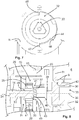
- the movement of the transmission element 31 from the coupling position 6 in the Entkoppelwolf 7 via the auxiliary release 30, in particular via the handle 32, according to FIG. 5 such as FIG. 8 The handle 32 has a contour 33, which in FIG. 7 and FIG. 8 is shown. In the contour 33, a tool can be introduced to rotate the handle 32 about the axis 36.
- FIG. 5 has a in the direction of the transmission element 31 extending cam 38 which eccentric to the axis 36 of the handle 32 is arranged.
- cam 38 acts against a stop 37 of the transmission element 31, whereby the transmission element 31 is displaced from the coupling position 6 in the Entkoppelwolf 7 linearly along the axis 34.
- FIG. 3, 4 such as FIG. 6 shown.
- the toothing 35 is detached and spaced from the toothing 25. Since in the locking position 4, the in FIG. 2 and FIG.
- a first energy storage 13 has a defined potential energy and exerts a force on the blocking element 13 in the direction of the transmission element 31, the blocking element 20 moves automatically in the Entkoppelwolf 7 of the transmission element 31 from the locking position 4 in the unlocked position 5.
- the first energy storage 13 is a spring element, which is stretched over the locking element 20, in which the locking element 20 from the unlocked position 5 according to FIG. 1 in the locking position 4 according to FIG. 2 is moved.
- the transmission element 31 and the drive 12 according to FIG. 1 and FIG. 8 there is a second energy storage 39, wherein the second energy storage 39 in the Entkoppel ein 7 has a defined energy, in particular is tensioned and a force on the stop 37, 48 of the transmission element 31 exerts. Due to the defined position of the handle 32 and the cam 38, it is not possible for the energy storage 39 to move the transmission element 31 from the Entkoppelgna 7 in the coupling position 6. For this purpose, it is necessary that the handle 32 is rotated back over the introduction of a tool in the contour 33 of the handle 32.
- the handle 32 according to FIG. 5 and FIG. 8 also has a seal 9, so that the interior of the tumbler 10 is reliably protected from environmental influences, such as moisture, dirt, etc.
- a securing ring 43 is arranged on the shaft 14, which reliably holds the transmission element 31 in the coupling position 6.
- FIG. 7 By way of example, a possible embodiment of the handle 32 with a possible contour 33 is shown, into which a tool can be inserted in order to rotate the handle 32 correspondingly about the axis 36.
- the handle 32 has two stops 44, 45, which in turn interact with counter-stops 46, 47.
- the counter-stops 46, 47 are arranged on the housing 11 side. Im shown Embodiment according to FIG. 7 the stop 44 abuts against the counter-stop 46.
- the axis 36 of the handle 32 is perpendicular to the plane of the movement axis 34 of the transmission element 31. Such an arrangement may be necessary according to the technical conditions. It is also conceivable that the axis 36 of the handle 32 is located in the plane of the movement axis 34 of the transmission element 31, which in FIG. 8 is provided.
- the embodiment according to FIG. 8 essentially corresponds to the embodiment according to FIG. 1 or according to FIG. 5 wherein a slider element 40 is arranged between the transmission element 31 and the handle 32. The slider element 40 engages upon actuation of the handle 32 on the stop 37 of the transmission element 31.
- a bearing element 41 is provided, on which the slide element 40 and the shaft 14, which connects the drive not explicitly shown with the transmission element 31, are mounted.
- the first energy storage 13 and the second energy storage 39 have the same function as according to FIG. 1 respectively.
- FIG. 5 the handle 32 has a thread 42 which causes a connection of the handle 32 with the housing 11. Instead of the thread 42 for the handle 32, it is also conceivable that an actuation of the handle 32, for example by a push button (push button has, for example, sliding bearing and can also be in connection with a comparable energy storage 39) can be performed.
- FIG. 5, FIG. 6 and FIG. 8 show, the teeth 25, 35 rounded tooth flanks, which is particularly advantageous in the movement of the transmission element 31 between the coupling position 6 and the Entkoppelwolf 7, in particular the lowest possible friction losses and low wear is recorded.
- the transmission element 31 has a free end face 49.
- the toothing 35 is rounded at its front side 49, at the same time each tooth flank of the toothing 35 is rounded at its free upper end 50.
- the blocking element 20 has a free end face 29.
- the toothing 25, in particular the tooth flanks of the blocking element 20 are rounded both to the free end face 29 and at the upper free end 28 of the toothing 25.
Landscapes
- Engineering & Computer Science (AREA)
- General Engineering & Computer Science (AREA)
- Mechanical Engineering (AREA)
- Physics & Mathematics (AREA)
- Electromagnetism (AREA)
- Lock And Its Accessories (AREA)
- Casings For Electric Apparatus (AREA)
Applications Claiming Priority (2)
| Application Number | Priority Date | Filing Date | Title |
|---|---|---|---|
| DE102012106722.8A DE102012106722B4 (de) | 2012-07-24 | 2012-07-24 | Zuhaltung für eine Zugangsschutzvorrichtung mit einer Hilfsentriegelung |
| PCT/EP2013/065486 WO2014016283A1 (de) | 2012-07-24 | 2013-07-23 | Zuhaltung für eine zugangsschutzvorrichtung mit einer hilfsentriegelung |
Publications (2)
| Publication Number | Publication Date |
|---|---|
| EP2877657A1 EP2877657A1 (de) | 2015-06-03 |
| EP2877657B1 true EP2877657B1 (de) | 2017-05-17 |
Family
ID=48808381
Family Applications (1)
| Application Number | Title | Priority Date | Filing Date |
|---|---|---|---|
| EP13739461.5A Active EP2877657B1 (de) | 2012-07-24 | 2013-07-23 | Zuhaltung für eine zugangsschutzvorrichtung mit einer hilfsentriegelung |
Country Status (4)
| Country | Link |
|---|---|
| EP (1) | EP2877657B1 (es) |
| DE (1) | DE102012106722B4 (es) |
| ES (1) | ES2637212T3 (es) |
| WO (1) | WO2014016283A1 (es) |
Cited By (1)
| Publication number | Priority date | Publication date | Assignee | Title |
|---|---|---|---|---|
| EP4198226A1 (en) * | 2021-12-15 | 2023-06-21 | Industrilås I Nässjö AB | Latch arrangement |
Families Citing this family (9)
| Publication number | Priority date | Publication date | Assignee | Title |
|---|---|---|---|---|
| DE102014011780A1 (de) * | 2014-08-12 | 2016-02-18 | Buchele Gmbh | Türanordnung |
| EP3505709B1 (en) * | 2017-12-28 | 2020-04-29 | Netatmo | Secure smart lock |
| EP3839177B1 (en) * | 2019-12-18 | 2023-08-02 | Airbus Operations GmbH | Aircraft door with a door lock having a self-opening latch and aircraft having such an aircraft door |
| AU2022314508A1 (en) * | 2021-07-21 | 2024-03-07 | Assa Abloy Australia Pty Limited | An electromechanical drop bolt |
| WO2023025543A1 (de) * | 2021-08-27 | 2023-03-02 | Hörmann KG Antriebstechnik | Signalbetätigbare torverriegelungsvorrichtung mit notentriegelung |
| DE102021122786A1 (de) | 2021-09-02 | 2023-03-02 | ABUS August Bremicker Söhne Kommanditgesellschaft | Schloss |
| US12000176B2 (en) * | 2021-09-13 | 2024-06-04 | The Boeing Company | Latching systems and methods |
| ES2989155T3 (es) * | 2021-12-03 | 2024-11-25 | Dormakaba Schweiz Ag | Dispositivo de retención electromecánico |
| US12366091B2 (en) * | 2022-10-27 | 2025-07-22 | Vision Engineering | Compact gear lock |
Family Cites Families (7)
| Publication number | Priority date | Publication date | Assignee | Title |
|---|---|---|---|---|
| FR2514059A1 (fr) * | 1981-10-07 | 1983-04-08 | France Ind Composants Batiment | Verrou motorise electroniquement dont l'axe du moteur est parallele a l'axe longitudinal des penes |
| FR2635553B1 (fr) * | 1988-08-19 | 1995-04-21 | Laperche Sa | Dispositif debrayable d'actionnement pour serrure et serrure comprenant un tel dispositif |
| DE3835349A1 (de) * | 1988-10-17 | 1990-04-19 | Winkhaus Fa August | Schloss |
| DE4404778C1 (de) * | 1994-02-10 | 1995-07-13 | Steffen Matschke | Elektromechanische Schließvorrichtung |
| DE19648146C1 (de) * | 1996-11-21 | 1998-06-18 | Roto Frank Ag | Vorrichtung zum Lösen beziehungsweise Herstellen einer Drehmitnahme |
| EP1160399B1 (de) * | 2000-05-30 | 2005-11-16 | Steinbach & Vollmann GmbH & Co. KG | Elektrisch betätigbares Schloss |
| DE102009060532A1 (de) * | 2009-12-23 | 2011-06-30 | K.A. Schmersal Holding GmbH & Co. KG, 42279 | Zuhaltung für ein Bauteil zum Verschließen einer Öffnung |
-
2012
- 2012-07-24 DE DE102012106722.8A patent/DE102012106722B4/de active Active
-
2013
- 2013-07-23 WO PCT/EP2013/065486 patent/WO2014016283A1/de not_active Ceased
- 2013-07-23 EP EP13739461.5A patent/EP2877657B1/de active Active
- 2013-07-23 ES ES13739461.5T patent/ES2637212T3/es active Active
Cited By (1)
| Publication number | Priority date | Publication date | Assignee | Title |
|---|---|---|---|---|
| EP4198226A1 (en) * | 2021-12-15 | 2023-06-21 | Industrilås I Nässjö AB | Latch arrangement |
Also Published As
| Publication number | Publication date |
|---|---|
| ES2637212T3 (es) | 2017-10-11 |
| DE102012106722A1 (de) | 2014-01-30 |
| DE102012106722B4 (de) | 2017-11-30 |
| EP2877657A1 (de) | 2015-06-03 |
| WO2014016283A1 (de) | 2014-01-30 |
Similar Documents
| Publication | Publication Date | Title |
|---|---|---|
| EP2877657B1 (de) | Zuhaltung für eine zugangsschutzvorrichtung mit einer hilfsentriegelung | |
| EP2029394B1 (de) | Bordmonitoreinrichtung | |
| EP2106488B1 (de) | Drehspannverschluss mit betätigungsgriffsicherung | |
| EP3517714B1 (de) | Zuhaltung und sicherheitseinrichtung mit geringen abmessungen | |
| DE60318568T2 (de) | Elektrischer Stellantrieb für Schwenktüren und dgl. | |
| EP4060147B1 (de) | Betätigungseinrichtungen für ein schloss sowie schlosssysteme mit derartigen betätigungseinrichtungen | |
| EP3784855A1 (de) | Kraftfahrzeugschloss | |
| EP2520746B1 (de) | Elektrisch betätigbares Schloss | |
| EP3686383B1 (de) | Türschloss mit motor | |
| DE202021104685U1 (de) | Vorrichtung zum Notentriegeln einer Tür sowie Schließeinheit mit Notentriegelungsfunktion | |
| DE4407912C2 (de) | Elektromechanisches Schloß | |
| EP3543436B1 (de) | Gegenschloss für eine standflügeltür | |
| EP2626490B1 (de) | Schlossanordnung | |
| EP3517715B1 (de) | Zuhaltung mit hilfsentriegelung | |
| WO2009095032A1 (de) | Sicherheitsschalter mit zuhaltungsfunktion zum zwangsöffnung von kontaktelementen sowie verfahren zum zwangsöffnen von kontaktelementen eines sicherheitsschalters mit verriegelungsfunktion | |
| EP2738324B1 (de) | Schloss mit einer freigebbaren Dreheinheit | |
| DE10318707B4 (de) | Sicherheitseinrichtung | |
| DE19526660A1 (de) | Elektromechanisches Schloß | |
| EP3312369B1 (de) | Verschlusselement einer immobilie sowie entsprechendes verfahren | |
| DE69502206T2 (de) | Verriegelbares, mechanisches Schloss | |
| DE102009009259B4 (de) | Zuhaltung für ein Bauteil zum Verschließen einer Öffnung | |
| EP2615229A2 (de) | Schließanlage | |
| DE102008023717B4 (de) | Vorrichtung zum lösbaren Verriegeln eines geschlossenen Zustandes einer Raumtrenneinrichtung, insbesondere Sicherheitsschalter mit Drehrichtungsumkehr der Betätigungsrichtung | |
| WO2008043711A2 (de) | Elektromechanische betätigungsvorrichtung für eine klappe oder dergleichen | |
| EP1522656B1 (de) | Handhabe für Türen oder Klappen von Fahrzeugen |
Legal Events
| Date | Code | Title | Description |
|---|---|---|---|
| PUAI | Public reference made under article 153(3) epc to a published international application that has entered the european phase |
Free format text: ORIGINAL CODE: 0009012 |
|
| 17P | Request for examination filed |
Effective date: 20150224 |
|
| AK | Designated contracting states |
Kind code of ref document: A1 Designated state(s): AL AT BE BG CH CY CZ DE DK EE ES FI FR GB GR HR HU IE IS IT LI LT LU LV MC MK MT NL NO PL PT RO RS SE SI SK SM TR |
|
| AX | Request for extension of the european patent |
Extension state: BA ME |
|
| DAX | Request for extension of the european patent (deleted) | ||
| 17Q | First examination report despatched |
Effective date: 20160420 |
|
| GRAP | Despatch of communication of intention to grant a patent |
Free format text: ORIGINAL CODE: EPIDOSNIGR1 |
|
| STAA | Information on the status of an ep patent application or granted ep patent |
Free format text: STATUS: GRANT OF PATENT IS INTENDED |
|
| INTG | Intention to grant announced |
Effective date: 20170102 |
|
| GRAS | Grant fee paid |
Free format text: ORIGINAL CODE: EPIDOSNIGR3 |
|
| GRAA | (expected) grant |
Free format text: ORIGINAL CODE: 0009210 |
|
| STAA | Information on the status of an ep patent application or granted ep patent |
Free format text: STATUS: THE PATENT HAS BEEN GRANTED |
|
| AK | Designated contracting states |
Kind code of ref document: B1 Designated state(s): AL AT BE BG CH CY CZ DE DK EE ES FI FR GB GR HR HU IE IS IT LI LT LU LV MC MK MT NL NO PL PT RO RS SE SI SK SM TR |
|
| REG | Reference to a national code |
Ref country code: GB Ref legal event code: FG4D Free format text: NOT ENGLISH |
|
| REG | Reference to a national code |
Ref country code: CH Ref legal event code: EP |
|
| REG | Reference to a national code |
Ref country code: IE Ref legal event code: FG4D Free format text: LANGUAGE OF EP DOCUMENT: GERMAN |
|
| REG | Reference to a national code |
Ref country code: AT Ref legal event code: REF Ref document number: 894622 Country of ref document: AT Kind code of ref document: T Effective date: 20170615 |
|
| REG | Reference to a national code |
Ref country code: DE Ref legal event code: R096 Ref document number: 502013007294 Country of ref document: DE |
|
| REG | Reference to a national code |
Ref country code: FR Ref legal event code: PLFP Year of fee payment: 5 |
|
| REG | Reference to a national code |
Ref country code: NL Ref legal event code: MP Effective date: 20170517 |
|
| REG | Reference to a national code |
Ref country code: LT Ref legal event code: MG4D |
|
| REG | Reference to a national code |
Ref country code: ES Ref legal event code: FG2A Ref document number: 2637212 Country of ref document: ES Kind code of ref document: T3 Effective date: 20171011 |
|
| PG25 | Lapsed in a contracting state [announced via postgrant information from national office to epo] |
Ref country code: HR Free format text: LAPSE BECAUSE OF FAILURE TO SUBMIT A TRANSLATION OF THE DESCRIPTION OR TO PAY THE FEE WITHIN THE PRESCRIBED TIME-LIMIT Effective date: 20170517 Ref country code: FI Free format text: LAPSE BECAUSE OF FAILURE TO SUBMIT A TRANSLATION OF THE DESCRIPTION OR TO PAY THE FEE WITHIN THE PRESCRIBED TIME-LIMIT Effective date: 20170517 Ref country code: LT Free format text: LAPSE BECAUSE OF FAILURE TO SUBMIT A TRANSLATION OF THE DESCRIPTION OR TO PAY THE FEE WITHIN THE PRESCRIBED TIME-LIMIT Effective date: 20170517 Ref country code: GR Free format text: LAPSE BECAUSE OF FAILURE TO SUBMIT A TRANSLATION OF THE DESCRIPTION OR TO PAY THE FEE WITHIN THE PRESCRIBED TIME-LIMIT Effective date: 20170818 Ref country code: NO Free format text: LAPSE BECAUSE OF FAILURE TO SUBMIT A TRANSLATION OF THE DESCRIPTION OR TO PAY THE FEE WITHIN THE PRESCRIBED TIME-LIMIT Effective date: 20170817 |
|
| PG25 | Lapsed in a contracting state [announced via postgrant information from national office to epo] |
Ref country code: PL Free format text: LAPSE BECAUSE OF FAILURE TO SUBMIT A TRANSLATION OF THE DESCRIPTION OR TO PAY THE FEE WITHIN THE PRESCRIBED TIME-LIMIT Effective date: 20170517 Ref country code: LV Free format text: LAPSE BECAUSE OF FAILURE TO SUBMIT A TRANSLATION OF THE DESCRIPTION OR TO PAY THE FEE WITHIN THE PRESCRIBED TIME-LIMIT Effective date: 20170517 Ref country code: RS Free format text: LAPSE BECAUSE OF FAILURE TO SUBMIT A TRANSLATION OF THE DESCRIPTION OR TO PAY THE FEE WITHIN THE PRESCRIBED TIME-LIMIT Effective date: 20170517 Ref country code: NL Free format text: LAPSE BECAUSE OF FAILURE TO SUBMIT A TRANSLATION OF THE DESCRIPTION OR TO PAY THE FEE WITHIN THE PRESCRIBED TIME-LIMIT Effective date: 20170517 Ref country code: SE Free format text: LAPSE BECAUSE OF FAILURE TO SUBMIT A TRANSLATION OF THE DESCRIPTION OR TO PAY THE FEE WITHIN THE PRESCRIBED TIME-LIMIT Effective date: 20170517 Ref country code: BG Free format text: LAPSE BECAUSE OF FAILURE TO SUBMIT A TRANSLATION OF THE DESCRIPTION OR TO PAY THE FEE WITHIN THE PRESCRIBED TIME-LIMIT Effective date: 20170817 Ref country code: IS Free format text: LAPSE BECAUSE OF FAILURE TO SUBMIT A TRANSLATION OF THE DESCRIPTION OR TO PAY THE FEE WITHIN THE PRESCRIBED TIME-LIMIT Effective date: 20170917 |
|
| PG25 | Lapsed in a contracting state [announced via postgrant information from national office to epo] |
Ref country code: EE Free format text: LAPSE BECAUSE OF FAILURE TO SUBMIT A TRANSLATION OF THE DESCRIPTION OR TO PAY THE FEE WITHIN THE PRESCRIBED TIME-LIMIT Effective date: 20170517 Ref country code: SK Free format text: LAPSE BECAUSE OF FAILURE TO SUBMIT A TRANSLATION OF THE DESCRIPTION OR TO PAY THE FEE WITHIN THE PRESCRIBED TIME-LIMIT Effective date: 20170517 Ref country code: RO Free format text: LAPSE BECAUSE OF FAILURE TO SUBMIT A TRANSLATION OF THE DESCRIPTION OR TO PAY THE FEE WITHIN THE PRESCRIBED TIME-LIMIT Effective date: 20170517 Ref country code: CZ Free format text: LAPSE BECAUSE OF FAILURE TO SUBMIT A TRANSLATION OF THE DESCRIPTION OR TO PAY THE FEE WITHIN THE PRESCRIBED TIME-LIMIT Effective date: 20170517 Ref country code: DK Free format text: LAPSE BECAUSE OF FAILURE TO SUBMIT A TRANSLATION OF THE DESCRIPTION OR TO PAY THE FEE WITHIN THE PRESCRIBED TIME-LIMIT Effective date: 20170517 |
|
| REG | Reference to a national code |
Ref country code: DE Ref legal event code: R097 Ref document number: 502013007294 Country of ref document: DE |
|
| PG25 | Lapsed in a contracting state [announced via postgrant information from national office to epo] |
Ref country code: SM Free format text: LAPSE BECAUSE OF FAILURE TO SUBMIT A TRANSLATION OF THE DESCRIPTION OR TO PAY THE FEE WITHIN THE PRESCRIBED TIME-LIMIT Effective date: 20170517 |
|
| REG | Reference to a national code |
Ref country code: CH Ref legal event code: PL |
|
| PLBE | No opposition filed within time limit |
Free format text: ORIGINAL CODE: 0009261 |
|
| STAA | Information on the status of an ep patent application or granted ep patent |
Free format text: STATUS: NO OPPOSITION FILED WITHIN TIME LIMIT |
|
| REG | Reference to a national code |
Ref country code: IE Ref legal event code: MM4A |
|
| 26N | No opposition filed |
Effective date: 20180220 |
|
| PG25 | Lapsed in a contracting state [announced via postgrant information from national office to epo] |
Ref country code: LI Free format text: LAPSE BECAUSE OF NON-PAYMENT OF DUE FEES Effective date: 20170731 Ref country code: CH Free format text: LAPSE BECAUSE OF NON-PAYMENT OF DUE FEES Effective date: 20170731 Ref country code: IE Free format text: LAPSE BECAUSE OF NON-PAYMENT OF DUE FEES Effective date: 20170723 |
|
| PG25 | Lapsed in a contracting state [announced via postgrant information from national office to epo] |
Ref country code: SI Free format text: LAPSE BECAUSE OF FAILURE TO SUBMIT A TRANSLATION OF THE DESCRIPTION OR TO PAY THE FEE WITHIN THE PRESCRIBED TIME-LIMIT Effective date: 20170517 |
|
| REG | Reference to a national code |
Ref country code: BE Ref legal event code: MM Effective date: 20170731 |
|
| PG25 | Lapsed in a contracting state [announced via postgrant information from national office to epo] |
Ref country code: LU Free format text: LAPSE BECAUSE OF NON-PAYMENT OF DUE FEES Effective date: 20170723 |
|
| REG | Reference to a national code |
Ref country code: FR Ref legal event code: PLFP Year of fee payment: 6 |
|
| PG25 | Lapsed in a contracting state [announced via postgrant information from national office to epo] |
Ref country code: BE Free format text: LAPSE BECAUSE OF NON-PAYMENT OF DUE FEES Effective date: 20170731 |
|
| PG25 | Lapsed in a contracting state [announced via postgrant information from national office to epo] |
Ref country code: MT Free format text: LAPSE BECAUSE OF FAILURE TO SUBMIT A TRANSLATION OF THE DESCRIPTION OR TO PAY THE FEE WITHIN THE PRESCRIBED TIME-LIMIT Effective date: 20170517 |
|
| PG25 | Lapsed in a contracting state [announced via postgrant information from national office to epo] |
Ref country code: MC Free format text: LAPSE BECAUSE OF FAILURE TO SUBMIT A TRANSLATION OF THE DESCRIPTION OR TO PAY THE FEE WITHIN THE PRESCRIBED TIME-LIMIT Effective date: 20170517 Ref country code: HU Free format text: LAPSE BECAUSE OF FAILURE TO SUBMIT A TRANSLATION OF THE DESCRIPTION OR TO PAY THE FEE WITHIN THE PRESCRIBED TIME-LIMIT; INVALID AB INITIO Effective date: 20130723 |
|
| REG | Reference to a national code |
Ref country code: AT Ref legal event code: MM01 Ref document number: 894622 Country of ref document: AT Kind code of ref document: T Effective date: 20180723 |
|
| PG25 | Lapsed in a contracting state [announced via postgrant information from national office to epo] |
Ref country code: CY Free format text: LAPSE BECAUSE OF FAILURE TO SUBMIT A TRANSLATION OF THE DESCRIPTION OR TO PAY THE FEE WITHIN THE PRESCRIBED TIME-LIMIT Effective date: 20170517 |
|
| PG25 | Lapsed in a contracting state [announced via postgrant information from national office to epo] |
Ref country code: MK Free format text: LAPSE BECAUSE OF FAILURE TO SUBMIT A TRANSLATION OF THE DESCRIPTION OR TO PAY THE FEE WITHIN THE PRESCRIBED TIME-LIMIT Effective date: 20170517 |
|
| PG25 | Lapsed in a contracting state [announced via postgrant information from national office to epo] |
Ref country code: AT Free format text: LAPSE BECAUSE OF NON-PAYMENT OF DUE FEES Effective date: 20180723 |
|
| PG25 | Lapsed in a contracting state [announced via postgrant information from national office to epo] |
Ref country code: TR Free format text: LAPSE BECAUSE OF FAILURE TO SUBMIT A TRANSLATION OF THE DESCRIPTION OR TO PAY THE FEE WITHIN THE PRESCRIBED TIME-LIMIT Effective date: 20170517 |
|
| PG25 | Lapsed in a contracting state [announced via postgrant information from national office to epo] |
Ref country code: PT Free format text: LAPSE BECAUSE OF FAILURE TO SUBMIT A TRANSLATION OF THE DESCRIPTION OR TO PAY THE FEE WITHIN THE PRESCRIBED TIME-LIMIT Effective date: 20170517 |
|
| PG25 | Lapsed in a contracting state [announced via postgrant information from national office to epo] |
Ref country code: AL Free format text: LAPSE BECAUSE OF FAILURE TO SUBMIT A TRANSLATION OF THE DESCRIPTION OR TO PAY THE FEE WITHIN THE PRESCRIBED TIME-LIMIT Effective date: 20170517 |
|
| REG | Reference to a national code |
Ref country code: DE Ref legal event code: R082 Ref document number: 502013007294 Country of ref document: DE Representative=s name: KALKOFF & PARTNER PATENTANWAELTE MBB, DE |
|
| PGFP | Annual fee paid to national office [announced via postgrant information from national office to epo] |
Ref country code: ES Payment date: 20250819 Year of fee payment: 13 |
|
| PGFP | Annual fee paid to national office [announced via postgrant information from national office to epo] |
Ref country code: DE Payment date: 20250725 Year of fee payment: 13 |
|
| PGFP | Annual fee paid to national office [announced via postgrant information from national office to epo] |
Ref country code: IT Payment date: 20250731 Year of fee payment: 13 |
|
| PGFP | Annual fee paid to national office [announced via postgrant information from national office to epo] |
Ref country code: GB Payment date: 20250724 Year of fee payment: 13 |
|
| PGFP | Annual fee paid to national office [announced via postgrant information from national office to epo] |
Ref country code: FR Payment date: 20250723 Year of fee payment: 13 |