EP2877824B1 - Selbstkalibrierender kalorimeter mithilfe von elektrischer substitution - Google Patents
Selbstkalibrierender kalorimeter mithilfe von elektrischer substitution Download PDFInfo
- Publication number
- EP2877824B1 EP2877824B1 EP13739711.3A EP13739711A EP2877824B1 EP 2877824 B1 EP2877824 B1 EP 2877824B1 EP 13739711 A EP13739711 A EP 13739711A EP 2877824 B1 EP2877824 B1 EP 2877824B1
- Authority
- EP
- European Patent Office
- Prior art keywords
- calorimeter
- measured
- measuring
- temperature
- inlet
- Prior art date
- Legal status (The legal status is an assumption and is not a legal conclusion. Google has not performed a legal analysis and makes no representation as to the accuracy of the status listed.)
- Active
Links
Images


Classifications
-
- G—PHYSICS
- G01—MEASURING; TESTING
- G01K—MEASURING TEMPERATURE; MEASURING QUANTITY OF HEAT; THERMALLY-SENSITIVE ELEMENTS NOT OTHERWISE PROVIDED FOR
- G01K19/00—Testing or calibrating calorimeters
-
- G—PHYSICS
- G01—MEASURING; TESTING
- G01K—MEASURING TEMPERATURE; MEASURING QUANTITY OF HEAT; THERMALLY-SENSITIVE ELEMENTS NOT OTHERWISE PROVIDED FOR
- G01K17/00—Measuring quantity of heat
- G01K17/003—Measuring quantity of heat for measuring the power of light beams, e.g. laser beams
Definitions
- the invention lies in the field of power measurement and more specifically relates to a calorimeter calibration device according to the invention comprising a heating resistive element, a source of cooling water, a series-regulated voltage source for supplying electric power to the heating element, at least one voltmeter for measuring the voltage at the terminals of said source, a first thermometer and a second thermometer for measuring the temperature of the cooling water respectively at the inlet and at the the output of said calorimeter, a frequency meter for measuring the flow of cooling water.
- the invention also relates to a method for calibrating such a calorimeter.
- the calorimeters of the prior art used to measure powers, in particular laser power, are generally provided with several measuring devices each dedicated to a particular physical quantity, such as, for example, the supply voltage or the temperature of the calorimeter or the flow rate. cooling water of said calorimeter.
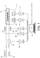
- the figure 1 schematically illustrates an acquisition chain used in a calorimeter 2 auto calibratable of the prior art having a resistive heating element 4 wound around the calorimeter 2, a first voltmeter 6 for measuring the supply voltage delivered by a source 8 to the resistive element 4, a second voltmeter 10 for measuring the voltage across a low resistance resistive shunt resistor 12 placed in series in the supply circuit of the heating element 4 and for measuring the feed current through this resistive element 4.
- the calorimeter of the figure 1 further comprises a water inlet 14 connected to a turbine 16 for supplying the cooling water of the calorimeter 2, and an outlet 18 for discharging the cooling water after passing through the calorimeter 2.
- the turbine 16 is adapted to deliver a frequency proportional to the cooling water flow rate .
- the variation of the temperature of the calorimeter 2 is measured by a first platinum resistance probe 20 connected to a first thermometer 22 and a second platinum resistance probe 24 connected to a second thermometer 26.
- the laser power to be measured is simulated by dissipating, by Joule effect, a corresponding electrical power well known in the resistive heating element 4 so as to reproduce at best the thermal effects resulting from the optical absorption of the beam.
- the operating principle is described below.
- the temperature rise Tc (° C) - Tf (° C) of the water at the calorimeter output is measured for a cooling flow Q (l / min) .
- the voltage drop across the terminals of the Standard shunt 12 is measured using voltmeter 10.
- the water flow cooling the calorimeter Q (l / min) is measured using the turbine 16 which generates a frequency signal in Hz. This measurement is carried out at using a frequency meter 28.
- Each of the instruments used to carry out the measurements described above is connected to a processing unit 30 which centralizes and saves all the data.
- the interfaces used may be parallel type IEEE, RS232 series, RS 422, RS 485, USB or Ethernet network type.
- a disadvantage of the acquisition chain of the figure 1 is derived from the fact that the measurements are made by five instruments of three different types each requiring a specific communication protocol with the processing unit 30.
- This acquisition chain can be simplified by using acquisition units or multiplexed voltmeters using a single microprocessor or a single microcontroller which by means of a multiplexing receives signals that are of very different natures (temperature, frequency and voltage) or even very different levels. Indeed, we go from a voltage to be measured from several hundred volts to a voltage to be measured a few tens of millivolts. If the desired accuracy for the measurements is high, the option that uses multiplexing is not very compatible with fast measurements at high resolutions and low noise. It is therefore preferable to keep five separate instruments each dedicated to a single quantity to be measured.
- the instruments used in the acquisition chain of the figure 1 could also be replaced by dedicated instrumentation boards installed on the PCI (Peripheral Component Interconnect) bus of a computer.
- PCI Peripheral Component Interconnect
- This solution is also not very compatible with high resolution and low noise measurements on signals that can also be very different (the PCI bus is powered by a switching power supply that is not very compatible with high metrological performance).
- An object of the invention is to overcome the disadvantages of the prior art described above.
- the invention consists in replacing all the conventional measuring instruments used in an acquisition chain or possibly several acquisition and processing cards plugged into the PCI (Peripheral Component Interconnect) bus of a computer by a single electronic card. of acquisition which embeds specific and optimized solutions for the different quantities to be measured.
- PCI Peripheral Component Interconnect
- the figure 1 previously described schematically illustrates an acquisition chain for measuring different physical quantities during the simulation of a laser power to be measured by dissipation of an equivalent electrical power in a resistive element.
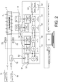
- all the measuring instruments used in the acquisition chain of the figure 1 are embedded on a single electronic card 31 comprising five autonomous acquisition chains 32, 34, 36, 38, and 40 each capable of processing, digitizing and measuring simultaneously and permanently a single physical quantity without being disturbed by multiplexing on different acquisition lines for different signals. Only the transfer of the digital data is multiplexed to a master microcontroller 42 via a common serial bus 44 of CAN or RS232 type. This multiplexing has no disruptive effect on the different analog signals. Only the master microcontroller 42 which centralizes the digital data is interfaced to the processing unit 30 which performs the backup and the data processing.
- Each of the autonomous acquisition chains 32 to 40 comprises a signal conditioning module dedicated to the measured physical quantity and a microcontroller dedicated to the processing of data relating to this physical quantity.
- the first acquisition channel 32 comprises a module 52 for filtering and shaping the frequency signal delivered by the turbine 16
- the acquisition chains 34 to 40 each comprise a module 54 comprising an amplification bridge, a filter and a 16-bit analog / digital converter.
- each of said acquisition chains 32 to 40 includes a 16-bit / 25MHz Freescale HCS12 55 microcontroller.
- Other microcontrollers can obviously be used without departing from the scope of the invention.
- the processing circuits specific to each size use passive and active components of high precision, very low offset, very low noise and very low thermal drift.
- Operational amplifiers used as follower and active filter components have a drift of their offsets of 0.1 ⁇ V / ° C.
- the voltage amplifiers used have a 0.005% non-linearity over their amplification range and a temperature drift of 5 ppm / ° C.
- the voltage references used have an error of ⁇ 0.02% and a temperature drift of 2 ppm / ° C.
- the resistances used in the measuring bridges and for the calibration circuits have an error of ⁇ 0.01% and a temperature drift of 2 ppm / ° C.
- the 16-bit digital analog converters used are fast and have a temperature drift of their offset of 3 ppm / ° C.
- the specific solutions that use these components are dedicated and optimized for each of the signals to be measured.
- the temperature of the water at the inlet of the calorimeter Tf is measured using a platinum resistance probe Pt100
- the temperature difference between the outlet and the water inlet of the calorimeter, (Tc - Tf) is to be measured with two platinum resistance probes placed respectively at the inlet and at the outlet of the calorimeter
- the water flow Q cooling the calorimeter is measured using a propeller turbine
- the current I and the voltage V are measured to determine the electric power dissipated by Joule effect in the calorimeter
- the water temperature at the calorimeter inlet is measured with a true resolution of 0.001 ° C using the 100 ohm platinum resistance probe 20, Pt100, which makes it possible to obtain, in association with a conventional metrological thermometer, a true resolution of 0.01 ° C.
- the emf (electromotive force) that corresponds to this voltage drop is amplified and filtered before being digitized using a 10V / 16-bit ADC (analog / digital converter).
- the corresponding electronic diagram is represented at figure 3 .
- means of calibrating the gain of the amplifier in voltage from a divider bridge equipped with high precision metal resistors (0.01%) are embedded on the electronic card 31. The gain of the amplifier measured periodically has a stability of the order of 0.01%.
- the flow measurements are carried out using a very high quality propeller turbine which delivers a frequency proportional to the instantaneous flow rate.
- This type of turbine works by magnetic induction.
- a permanent magnet inserted in the helix induces a sinusoidal electrical signal whose frequency is proportional to the rotation frequency of the helix.
- Magnetic induction can unfortunately be disturbed by fluctuations and harmonics across the public grid.
- the induced signal is framed by two active linear filters BESSEL type respectively high pass of order 4 and low pass of order 4.
- the figure 6 represents the electrical diagram of such a filter.
- the true resolution thus obtained on the flow is equal to 0.001 liter / minute.
- FIGS. 7a to 7d represent the electrical diagrams of the power supplies of the electronic functions previously described. These are linear type rectified, strongly filtered and regulated. They offer low residual ripples of a few millivolts ⁇ 15 V and have two different analog masses decoupled; GND and GND_DEBIT, which galvanically isolate the low continuous signals of the same nature (the temperatures) of the signal sinusoidal frequency delivered by the turbine 16.
- shunts or standard resistances with very low uncertainty (0.01%) and very low temperature dependence (qqs ppm / ° C) are used. These shunts and resistors can be directly embedded on the electronic card 31, which can be a definite advantage in terms of integration.
- autonomous measuring instruments, voltmeters, frequency meters and thermometers are replaced by a single onboard card 31 which comprises as many autonomous processing channels as physical quantities to be measured.
- An easily integrable solution is thus obtained for a low final cost.
- This card can be embedded with the object to be instrumented, which can be important in terms of portability of the application.
- each track is built using specific electronic solutions and optimized to obtain the best final result on the quantity to be measured. High performance components can be associated with the case by case as needed.
- the card 31 can ship its own series-regulated linear power supplies perfectly dedicated to metrology and which may have decoupled analog masses if the signals to operate require. It can also embark the calibration circuits for measurement and control over time of the gains of the different amplifiers used. Thus, associated automatic calibration procedures available at any time can be used.
- each of the channels uses a dedicated microcontroller in which will be programmed the software code (compiled in assembler) autonomous specific to its application. The connection with an external computer is reduced to a single RS232, RS422, RS485, USB or Ethernet serial interface via a master microcontroller. This same microcontroller master can also be interfaced with various external devices, such as alphanumeric displays without the need to use a computer for reading the results.
Landscapes
- Physics & Mathematics (AREA)
- General Physics & Mathematics (AREA)
- Optics & Photonics (AREA)
- Chemical & Material Sciences (AREA)
- Engineering & Computer Science (AREA)
- Combustion & Propulsion (AREA)
- Investigating Or Analyzing Materials Using Thermal Means (AREA)
- Photometry And Measurement Of Optical Pulse Characteristics (AREA)
Claims (3)
- Kalibriervorrichtung für ein Laserkalorimeter (2), das durch elektrische Substitution selbstkalibrierend ist, enthaltend
Mittel (2, 4, 6, 8, 10, 12, 14, 16, 18, 20, 22, 24, 26) zum Messen einer Vielzahl von physikalischen Größen verschiedener Arten und Größenordnungen,
eine einzelne Erfassungskarte (31), die für jede zu messende Größe eine eigenständige Erfassungskette (32, 34, 36, 38, 40) umfasst, die für die zu messende Größe spezifische Verarbeitungsschaltungen enthält, wobei jede eigenständige Erfassungskette einen Mikrocontroller (55) aufweist, der der Verarbeitung der zu messenden Größe zugeordnet ist,
ein Heizelement (4),
eine seriell geregelte Spannungsquelle (8), die dazu bestimmt ist, dem Heizelement (4) elektrische Energie zuzuführen,
eine Kühlwasserquelle,
wobei die Mittel (2, 4, 6, 8, 10, 12, 14, 16, 18, 20, 22, 24, 26) zum Messen einer Vielzahl von physikalischen Größen verschiedener Arten und Größenordnungen enthalten:zumindest ein Voltmeter, das dazu bestimmt ist, die Spannung an den Anschlüssen der Spannungsquelle zu messen,zumindest ein Thermometer, das dazu bestimmt ist, die Temperatur des Kühlwassers am Einlass bzw. Auslass des Kalorimeters (12) zu messen, wobei das Thermometer zumindest zwei Widerstände umfasst, die jeweils am Einlass bzw. Auslass des Kalorimeters über eine Wheatstone-Brücke angeordnet sind, um Temperaturmessungen durchzuführen, undeinen Frequenzmesser, der dazu bestimmt ist, den Kühlwasserdurchsatz zu messen. - Vorrichtung nach Anspruch 1, wobei die Mikrocontroller (32, 34, 36, 38, 40) der verschiedenen eigenständigen Erfassungsketten mit einem Master-Mikrocontroller (42) verbunden sind, der über einen gemeinsamen seriellen Datenbus mit einer Verarbeitungseinheit (30) verbunden ist.
- Verfahren zum Kalibrieren eines Laserkalorimeters (2), das durch elektrische Substitution selbstkalibrierend ist, enthaltend Mittel zum Messen einer Vielzahl von physikalischen Größen verschiedener Arten und Größenordnungen,
wobei
jede physikalische Größe gemessen und in einer eigenständigen Erfassungskette (32, 34, 36, 38, 40) verarbeitet wird, die für die zu messende Größe spezifische Verarbeitungsschaltungen enthält,
bei welchem Verfahren- die Leistung eines Laserstrahls, die mit Hilfe des Kalorimeters (2) gemessen werden soll, simuliert wird, indem durch Joule-Effekt eine der Laserleistung entsprechende elektrische Leistung an ein Heizelement (4), das um einen Absorber des Kalorimeters (2) gewickelt ist, abgeführt wird, um die thermischen Effekte zu reproduzieren, die sich aus der optischen Absorption des Laserstrahls ergeben, und- die Temperaturdifferenz zwischen Wasserauslass und -einlass des Kalorimeters mit Hilfe von zwei Platin-Widerstandsthermometern gemessen wird, die jeweils am Einlass und am Auslass des Kalorimeters über eine Wheatstone-Brücke angeordnet sind, um schnelle Temperaturmessungen mit hohen Auflösungen und geringem Rauschen durchzuführen,- die in das Heizelement (4) abgeführte elektrische Leistung in Abhängigkeit von der Temperaturschwankung einer gegebenen Kühlwassermenge zwischen dem Einlass (14) und dem Auslass (18) des Kalorimeters gemessen wird,- jede gemessene physikalische Größe in einer eigenständigen Erfassungskette (32, 34, 36, 38, 40) mittels Verarbeitungsschaltungen, die spezifisch der gemessenen Größe zugeordnet sind, und mittels eines Mikrocontrollers (55) verarbeitet wird, der der Verarbeitung der zu messenden Größe zugeordnet ist.
Applications Claiming Priority (2)
| Application Number | Priority Date | Filing Date | Title |
|---|---|---|---|
| FR1257166A FR2993981B1 (fr) | 2012-07-24 | 2012-07-24 | Calorimetre auto-etalonnable par substitution electrique |
| PCT/EP2013/065471 WO2014016273A2 (fr) | 2012-07-24 | 2013-07-23 | Calorimetre auto-etalonnable par substitution electrique |
Publications (2)
| Publication Number | Publication Date |
|---|---|
| EP2877824A2 EP2877824A2 (de) | 2015-06-03 |
| EP2877824B1 true EP2877824B1 (de) | 2019-09-18 |
Family
ID=47191895
Family Applications (1)
| Application Number | Title | Priority Date | Filing Date |
|---|---|---|---|
| EP13739711.3A Active EP2877824B1 (de) | 2012-07-24 | 2013-07-23 | Selbstkalibrierender kalorimeter mithilfe von elektrischer substitution |
Country Status (4)
| Country | Link |
|---|---|
| US (1) | US10228295B2 (de) |
| EP (1) | EP2877824B1 (de) |
| FR (1) | FR2993981B1 (de) |
| WO (1) | WO2014016273A2 (de) |
Families Citing this family (5)
| Publication number | Priority date | Publication date | Assignee | Title |
|---|---|---|---|---|
| FR2993981B1 (fr) * | 2012-07-24 | 2015-04-03 | Commissariat Energie Atomique | Calorimetre auto-etalonnable par substitution electrique |
| CN107907247B (zh) * | 2017-11-27 | 2019-10-25 | 中国电子科技集团公司第四十八研究所 | 一种大热流激光校准装置 |
| RU2708708C1 (ru) * | 2019-02-13 | 2019-12-11 | Дмитрий Владимирович Протасеня | Устройство для поиска и характеризации поверхностных дефектов в оптических материалах |
| CN114544039B (zh) * | 2022-03-11 | 2025-12-12 | 中国计量大学 | 一种基于电阻焦耳热效应的加速量热仪检测性能校准方法 |
| WO2025091051A1 (en) * | 2023-10-26 | 2025-05-01 | Bird Technologies Group Inc. | Radio frequency calorimeter |
Family Cites Families (30)
| Publication number | Priority date | Publication date | Assignee | Title |
|---|---|---|---|---|
| US4158810A (en) * | 1974-10-21 | 1979-06-19 | Leskovar Silvin M | Telemetering post for measuring variables in a high-voltage overhead line |
| US4033186A (en) * | 1976-08-06 | 1977-07-05 | Don Bresie | Method and apparatus for down hole pressure and temperature measurement |
| FR2619232B1 (fr) * | 1987-08-07 | 1994-04-29 | Muller & Cie Ets M | Equipement d'acquisition et de traitement de donnees pour centre de controle technique automobile |
| CN1065979C (zh) * | 1997-07-25 | 2001-05-16 | 清华大学 | 小型光盘盘片多功能测试仪 |
| US6331075B1 (en) * | 1998-05-01 | 2001-12-18 | Administrator, National Aeronautics And Space Administration | Device and method for measuring thermal conductivity of thin films |
| US6865241B1 (en) * | 1999-12-15 | 2005-03-08 | Lexmark International, Inc. | Method and apparatus for sampling digital data at a virtually constant rate, and transferring that data into a non-constant sampling rate device |
| US7385392B2 (en) * | 2000-11-13 | 2008-06-10 | Jentek Sensors, Inc. | Eddy current sensing arrays and system |
| CH694899A5 (fr) * | 2000-11-29 | 2005-08-31 | Volotek Sa | Systeme d'acquisition de donnees et jeu de cartes electroniques pour un tel systeme. |
| US6694281B2 (en) * | 2001-07-12 | 2004-02-17 | Seagate Technology Llc | Real time signal analysis of a remote block data storage device |
| US20030135547A1 (en) * | 2001-07-23 | 2003-07-17 | Kent J. Thomas | Extensible modular communication executive with active message queue and intelligent message pre-validation |
| FR2836248B1 (fr) * | 2002-02-18 | 2005-01-28 | Ermme | Module d'acquisition a entree universelle pour la mesure de grandeurs physiques |
| US7077564B2 (en) * | 2003-06-18 | 2006-07-18 | Coherent, Inc. | Laser power meter |
| US7312615B2 (en) * | 2003-06-27 | 2007-12-25 | Ati Industrial Automation, Inc. | System and method for communicating calibration data |
| ITMI20050290A1 (it) * | 2005-02-24 | 2006-08-25 | Consiglio Nazionale Ricerche | Dispositivo bolometrico a cavita' ricevente per la misura della potenza di un fasscio di microonde ad alta frequenza e procedimento per il rivestimento della superficie interna di detta cavita' |
| CN2904152Y (zh) * | 2006-02-13 | 2007-05-23 | 同济大学 | 多源数据采集系统 |
| US7411533B2 (en) * | 2006-10-05 | 2008-08-12 | Intel Corporation | ADC for simultaneous multiple analog inputs |
| US8050881B1 (en) * | 2007-10-18 | 2011-11-01 | Enbiomedic | Post data-collection synchronization for approximation of simultaneous data |
| FR2925163B1 (fr) * | 2007-12-12 | 2010-02-26 | Centre Nat Rech Scient | Procede et appareil d'analyse thermique |
| CN201130369Y (zh) * | 2007-12-20 | 2008-10-08 | 陕西海泰电子有限责任公司 | 一种基于vxi总线的多通道同步数据采集卡 |
| CN101308171B (zh) * | 2008-05-30 | 2011-03-23 | 安徽大学 | Pci总线电能质量瞬态事件采集卡及其采集方法 |
| CN101451917B (zh) * | 2008-12-31 | 2011-06-08 | 合肥工业大学 | 汽车内室操纵力舒适度评价系统及评价方法 |
| CN101701879A (zh) * | 2009-11-23 | 2010-05-05 | 浙江大学 | 比例电磁铁性能测试系统 |
| US8485724B2 (en) * | 2010-03-31 | 2013-07-16 | Microchip Technology Incorporated | Thermocouple electromotive force voltage to temperature converter with integrated cold-junction compensation and linearization |
| CN101871984A (zh) * | 2010-05-28 | 2010-10-27 | 中国船舶重工集团公司第七一二研究所 | 船舶电能质量检测装置及检测方法 |
| WO2012030861A1 (en) * | 2010-08-31 | 2012-03-08 | Streamline Automation, Llc | Miniaturized thermocouple scanner system |
| CN102262166B (zh) * | 2011-04-08 | 2013-01-09 | 内蒙古农业大学 | 风洞风速廓线仪及其控制方法 |
| GB201121640D0 (en) * | 2011-12-16 | 2012-01-25 | Element Six Ltd | Large area optical synthetic polycrystalline diamond window |
| FR2993981B1 (fr) * | 2012-07-24 | 2015-04-03 | Commissariat Energie Atomique | Calorimetre auto-etalonnable par substitution electrique |
| US9354126B2 (en) * | 2012-11-30 | 2016-05-31 | International Business Machines Corporation | Calibrating thermal behavior of electronics |
| CN103149395B (zh) * | 2013-03-01 | 2015-09-23 | 天津大学 | 一种用于多路模拟量采集卡的温度补偿方法 |
-
2012
- 2012-07-24 FR FR1257166A patent/FR2993981B1/fr active Active
-
2013
- 2013-07-23 WO PCT/EP2013/065471 patent/WO2014016273A2/fr not_active Ceased
- 2013-07-23 US US14/414,836 patent/US10228295B2/en not_active Expired - Fee Related
- 2013-07-23 EP EP13739711.3A patent/EP2877824B1/de active Active
Non-Patent Citations (1)
| Title |
|---|
| None * |
Also Published As
| Publication number | Publication date |
|---|---|
| EP2877824A2 (de) | 2015-06-03 |
| FR2993981A1 (fr) | 2014-01-31 |
| FR2993981B1 (fr) | 2015-04-03 |
| WO2014016273A2 (fr) | 2014-01-30 |
| US10228295B2 (en) | 2019-03-12 |
| WO2014016273A3 (fr) | 2014-09-04 |
| US20150192480A1 (en) | 2015-07-09 |
Similar Documents
| Publication | Publication Date | Title |
|---|---|---|
| EP2877824A2 (de) | Selbstkalibrierendes kalorimeter mit stromsubstitution | |
| EP0390843B1 (de) | Kodierung mehrerer messwertgrössen an einem reifen | |
| EP2343561B1 (de) | Verfahren und System zur Überprüfung des Kalibrierungszustandes eines an Bord eines Schienenfahrzeugs installierten Elektrizitätszählers | |
| EP0919800B1 (de) | Verfahren zur Messung der Viskosität eines Fluidums | |
| EP0293310B1 (de) | Verfahren zum Kalibrieren eines elektronischen Drehmomentschlüssels | |
| FR2975187A1 (fr) | Mesure differentielle de tension | |
| FR2624275A1 (fr) | Circuits et procedes d'etalonnage pour etalonner des ohmmetres tout en compensant l'erreur inherente a la resistance des cordons de raccordement | |
| EP2694920B1 (de) | Verfahren zum korrigieren der messung der spannung an den anschlüssen eines sensors | |
| FR2683313A1 (fr) | Dispositif de mesure de parametres, notamment de parametres relatifs a des roues d'avion ou de vehicule. | |
| FR2998062A1 (fr) | Circuit de mesure pour determiner la resistance d'un composant resistant de capteur | |
| EP3086131A1 (de) | Strommessvorrichtung in einem elektrischen schaltkreis | |
| EP2560066B1 (de) | Verfahren zum Einstellen einer Referenzspannung auf Basis eines Bandgap-Schaltkreises | |
| FR2496896A1 (fr) | Dispositif de mesure de puissance ou d'energie electriques | |
| FR2489509A1 (fr) | Procede et dispositif de mesure electrique de quantites de chaleur | |
| CA2476009A1 (fr) | Module d'acquisition a entree universelle pour la mesure de grandeurs physiques | |
| FR2690524A1 (fr) | Procédé de compensation en température d'un pont de jauges de mesure de pression. | |
| FR2536854A1 (fr) | Dispositif de mesure de la temperature | |
| FR2924287A1 (fr) | Module d'entrees analogiques pour equipement d'automatisme | |
| EP1630533B1 (de) | Temperaturmessvorrichtung in einem thermischen Energiezähler | |
| FR2941777A1 (fr) | Mesure de debit dans un ventilateur. | |
| FR2691806A1 (fr) | Dispositif de mesure électrotechnique polyvalent. | |
| FR2472180A1 (fr) | Procede et dispositif pour determination de l'energie thermique cedee | |
| EP2784529B1 (de) | System zur Bestimmung mindestens eines Bewegungsparameters eines mobilen Organs in Bezug auf eine feststehende Struktur | |
| EP0616292A1 (de) | Multiplizierschaltung mit Widerstandsnetzwerken und einem diese Schaltung enthaltenden Elektrizitätszähler | |
| EP4567437A1 (de) | Messung der phase einer komplexen impedanz durch schwellenwert |
Legal Events
| Date | Code | Title | Description |
|---|---|---|---|
| PUAI | Public reference made under article 153(3) epc to a published international application that has entered the european phase |
Free format text: ORIGINAL CODE: 0009012 |
|
| 17P | Request for examination filed |
Effective date: 20150203 |
|
| AK | Designated contracting states |
Kind code of ref document: A2 Designated state(s): AL AT BE BG CH CY CZ DE DK EE ES FI FR GB GR HR HU IE IS IT LI LT LU LV MC MK MT NL NO PL PT RO RS SE SI SK SM TR |
|
| AX | Request for extension of the european patent |
Extension state: BA ME |
|
| DAX | Request for extension of the european patent (deleted) | ||
| STAA | Information on the status of an ep patent application or granted ep patent |
Free format text: STATUS: EXAMINATION IS IN PROGRESS |
|
| 17Q | First examination report despatched |
Effective date: 20170127 |
|
| GRAP | Despatch of communication of intention to grant a patent |
Free format text: ORIGINAL CODE: EPIDOSNIGR1 |
|
| STAA | Information on the status of an ep patent application or granted ep patent |
Free format text: STATUS: GRANT OF PATENT IS INTENDED |
|
| INTG | Intention to grant announced |
Effective date: 20190409 |
|
| GRAS | Grant fee paid |
Free format text: ORIGINAL CODE: EPIDOSNIGR3 |
|
| GRAA | (expected) grant |
Free format text: ORIGINAL CODE: 0009210 |
|
| STAA | Information on the status of an ep patent application or granted ep patent |
Free format text: STATUS: THE PATENT HAS BEEN GRANTED |
|
| AK | Designated contracting states |
Kind code of ref document: B1 Designated state(s): AL AT BE BG CH CY CZ DE DK EE ES FI FR GB GR HR HU IE IS IT LI LT LU LV MC MK MT NL NO PL PT RO RS SE SI SK SM TR |
|
| REG | Reference to a national code |
Ref country code: GB Ref legal event code: FG4D Free format text: NOT ENGLISH |
|
| REG | Reference to a national code |
Ref country code: CH Ref legal event code: EP |
|
| REG | Reference to a national code |
Ref country code: DE Ref legal event code: R096 Ref document number: 602013060683 Country of ref document: DE |
|
| REG | Reference to a national code |
Ref country code: AT Ref legal event code: REF Ref document number: 1181893 Country of ref document: AT Kind code of ref document: T Effective date: 20191015 |
|
| REG | Reference to a national code |
Ref country code: IE Ref legal event code: FG4D Free format text: LANGUAGE OF EP DOCUMENT: FRENCH |
|
| REG | Reference to a national code |
Ref country code: NL Ref legal event code: MP Effective date: 20190918 |
|
| PG25 | Lapsed in a contracting state [announced via postgrant information from national office to epo] |
Ref country code: HR Free format text: LAPSE BECAUSE OF FAILURE TO SUBMIT A TRANSLATION OF THE DESCRIPTION OR TO PAY THE FEE WITHIN THE PRESCRIBED TIME-LIMIT Effective date: 20190918 Ref country code: LT Free format text: LAPSE BECAUSE OF FAILURE TO SUBMIT A TRANSLATION OF THE DESCRIPTION OR TO PAY THE FEE WITHIN THE PRESCRIBED TIME-LIMIT Effective date: 20190918 Ref country code: NO Free format text: LAPSE BECAUSE OF FAILURE TO SUBMIT A TRANSLATION OF THE DESCRIPTION OR TO PAY THE FEE WITHIN THE PRESCRIBED TIME-LIMIT Effective date: 20191218 Ref country code: BG Free format text: LAPSE BECAUSE OF FAILURE TO SUBMIT A TRANSLATION OF THE DESCRIPTION OR TO PAY THE FEE WITHIN THE PRESCRIBED TIME-LIMIT Effective date: 20191218 Ref country code: FI Free format text: LAPSE BECAUSE OF FAILURE TO SUBMIT A TRANSLATION OF THE DESCRIPTION OR TO PAY THE FEE WITHIN THE PRESCRIBED TIME-LIMIT Effective date: 20190918 Ref country code: SE Free format text: LAPSE BECAUSE OF FAILURE TO SUBMIT A TRANSLATION OF THE DESCRIPTION OR TO PAY THE FEE WITHIN THE PRESCRIBED TIME-LIMIT Effective date: 20190918 |
|
| REG | Reference to a national code |
Ref country code: LT Ref legal event code: MG4D |
|
| PG25 | Lapsed in a contracting state [announced via postgrant information from national office to epo] |
Ref country code: RS Free format text: LAPSE BECAUSE OF FAILURE TO SUBMIT A TRANSLATION OF THE DESCRIPTION OR TO PAY THE FEE WITHIN THE PRESCRIBED TIME-LIMIT Effective date: 20190918 Ref country code: LV Free format text: LAPSE BECAUSE OF FAILURE TO SUBMIT A TRANSLATION OF THE DESCRIPTION OR TO PAY THE FEE WITHIN THE PRESCRIBED TIME-LIMIT Effective date: 20190918 Ref country code: GR Free format text: LAPSE BECAUSE OF FAILURE TO SUBMIT A TRANSLATION OF THE DESCRIPTION OR TO PAY THE FEE WITHIN THE PRESCRIBED TIME-LIMIT Effective date: 20191219 Ref country code: AL Free format text: LAPSE BECAUSE OF FAILURE TO SUBMIT A TRANSLATION OF THE DESCRIPTION OR TO PAY THE FEE WITHIN THE PRESCRIBED TIME-LIMIT Effective date: 20190918 |
|
| REG | Reference to a national code |
Ref country code: AT Ref legal event code: MK05 Ref document number: 1181893 Country of ref document: AT Kind code of ref document: T Effective date: 20190918 |
|
| PG25 | Lapsed in a contracting state [announced via postgrant information from national office to epo] |
Ref country code: AT Free format text: LAPSE BECAUSE OF FAILURE TO SUBMIT A TRANSLATION OF THE DESCRIPTION OR TO PAY THE FEE WITHIN THE PRESCRIBED TIME-LIMIT Effective date: 20190918 Ref country code: NL Free format text: LAPSE BECAUSE OF FAILURE TO SUBMIT A TRANSLATION OF THE DESCRIPTION OR TO PAY THE FEE WITHIN THE PRESCRIBED TIME-LIMIT Effective date: 20190918 Ref country code: EE Free format text: LAPSE BECAUSE OF FAILURE TO SUBMIT A TRANSLATION OF THE DESCRIPTION OR TO PAY THE FEE WITHIN THE PRESCRIBED TIME-LIMIT Effective date: 20190918 Ref country code: PT Free format text: LAPSE BECAUSE OF FAILURE TO SUBMIT A TRANSLATION OF THE DESCRIPTION OR TO PAY THE FEE WITHIN THE PRESCRIBED TIME-LIMIT Effective date: 20200120 Ref country code: RO Free format text: LAPSE BECAUSE OF FAILURE TO SUBMIT A TRANSLATION OF THE DESCRIPTION OR TO PAY THE FEE WITHIN THE PRESCRIBED TIME-LIMIT Effective date: 20190918 Ref country code: IT Free format text: LAPSE BECAUSE OF FAILURE TO SUBMIT A TRANSLATION OF THE DESCRIPTION OR TO PAY THE FEE WITHIN THE PRESCRIBED TIME-LIMIT Effective date: 20190918 Ref country code: PL Free format text: LAPSE BECAUSE OF FAILURE TO SUBMIT A TRANSLATION OF THE DESCRIPTION OR TO PAY THE FEE WITHIN THE PRESCRIBED TIME-LIMIT Effective date: 20190918 Ref country code: ES Free format text: LAPSE BECAUSE OF FAILURE TO SUBMIT A TRANSLATION OF THE DESCRIPTION OR TO PAY THE FEE WITHIN THE PRESCRIBED TIME-LIMIT Effective date: 20190918 |
|
| PG25 | Lapsed in a contracting state [announced via postgrant information from national office to epo] |
Ref country code: SK Free format text: LAPSE BECAUSE OF FAILURE TO SUBMIT A TRANSLATION OF THE DESCRIPTION OR TO PAY THE FEE WITHIN THE PRESCRIBED TIME-LIMIT Effective date: 20190918 Ref country code: CZ Free format text: LAPSE BECAUSE OF FAILURE TO SUBMIT A TRANSLATION OF THE DESCRIPTION OR TO PAY THE FEE WITHIN THE PRESCRIBED TIME-LIMIT Effective date: 20190918 Ref country code: IS Free format text: LAPSE BECAUSE OF FAILURE TO SUBMIT A TRANSLATION OF THE DESCRIPTION OR TO PAY THE FEE WITHIN THE PRESCRIBED TIME-LIMIT Effective date: 20200224 Ref country code: SM Free format text: LAPSE BECAUSE OF FAILURE TO SUBMIT A TRANSLATION OF THE DESCRIPTION OR TO PAY THE FEE WITHIN THE PRESCRIBED TIME-LIMIT Effective date: 20190918 |
|
| REG | Reference to a national code |
Ref country code: DE Ref legal event code: R097 Ref document number: 602013060683 Country of ref document: DE |
|
| PLBE | No opposition filed within time limit |
Free format text: ORIGINAL CODE: 0009261 |
|
| STAA | Information on the status of an ep patent application or granted ep patent |
Free format text: STATUS: NO OPPOSITION FILED WITHIN TIME LIMIT |
|
| PG2D | Information on lapse in contracting state deleted |
Ref country code: IS |
|
| PG25 | Lapsed in a contracting state [announced via postgrant information from national office to epo] |
Ref country code: DK Free format text: LAPSE BECAUSE OF FAILURE TO SUBMIT A TRANSLATION OF THE DESCRIPTION OR TO PAY THE FEE WITHIN THE PRESCRIBED TIME-LIMIT Effective date: 20190918 Ref country code: IS Free format text: LAPSE BECAUSE OF FAILURE TO SUBMIT A TRANSLATION OF THE DESCRIPTION OR TO PAY THE FEE WITHIN THE PRESCRIBED TIME-LIMIT Effective date: 20200119 |
|
| 26N | No opposition filed |
Effective date: 20200619 |
|
| PG25 | Lapsed in a contracting state [announced via postgrant information from national office to epo] |
Ref country code: SI Free format text: LAPSE BECAUSE OF FAILURE TO SUBMIT A TRANSLATION OF THE DESCRIPTION OR TO PAY THE FEE WITHIN THE PRESCRIBED TIME-LIMIT Effective date: 20190918 |
|
| REG | Reference to a national code |
Ref country code: DE Ref legal event code: R119 Ref document number: 602013060683 Country of ref document: DE |
|
| PG25 | Lapsed in a contracting state [announced via postgrant information from national office to epo] |
Ref country code: MC Free format text: LAPSE BECAUSE OF FAILURE TO SUBMIT A TRANSLATION OF THE DESCRIPTION OR TO PAY THE FEE WITHIN THE PRESCRIBED TIME-LIMIT Effective date: 20190918 |
|
| REG | Reference to a national code |
Ref country code: CH Ref legal event code: PL |
|
| GBPC | Gb: european patent ceased through non-payment of renewal fee |
Effective date: 20200723 |
|
| REG | Reference to a national code |
Ref country code: BE Ref legal event code: MM Effective date: 20200731 |
|
| PG25 | Lapsed in a contracting state [announced via postgrant information from national office to epo] |
Ref country code: GB Free format text: LAPSE BECAUSE OF NON-PAYMENT OF DUE FEES Effective date: 20200723 Ref country code: LI Free format text: LAPSE BECAUSE OF NON-PAYMENT OF DUE FEES Effective date: 20200731 Ref country code: CH Free format text: LAPSE BECAUSE OF NON-PAYMENT OF DUE FEES Effective date: 20200731 Ref country code: LU Free format text: LAPSE BECAUSE OF NON-PAYMENT OF DUE FEES Effective date: 20200723 |
|
| PG25 | Lapsed in a contracting state [announced via postgrant information from national office to epo] |
Ref country code: BE Free format text: LAPSE BECAUSE OF NON-PAYMENT OF DUE FEES Effective date: 20200731 Ref country code: DE Free format text: LAPSE BECAUSE OF NON-PAYMENT OF DUE FEES Effective date: 20210202 |
|
| PG25 | Lapsed in a contracting state [announced via postgrant information from national office to epo] |
Ref country code: IE Free format text: LAPSE BECAUSE OF NON-PAYMENT OF DUE FEES Effective date: 20200723 |
|
| PG25 | Lapsed in a contracting state [announced via postgrant information from national office to epo] |
Ref country code: TR Free format text: LAPSE BECAUSE OF FAILURE TO SUBMIT A TRANSLATION OF THE DESCRIPTION OR TO PAY THE FEE WITHIN THE PRESCRIBED TIME-LIMIT Effective date: 20190918 Ref country code: MT Free format text: LAPSE BECAUSE OF FAILURE TO SUBMIT A TRANSLATION OF THE DESCRIPTION OR TO PAY THE FEE WITHIN THE PRESCRIBED TIME-LIMIT Effective date: 20190918 Ref country code: CY Free format text: LAPSE BECAUSE OF FAILURE TO SUBMIT A TRANSLATION OF THE DESCRIPTION OR TO PAY THE FEE WITHIN THE PRESCRIBED TIME-LIMIT Effective date: 20190918 |
|
| PG25 | Lapsed in a contracting state [announced via postgrant information from national office to epo] |
Ref country code: MK Free format text: LAPSE BECAUSE OF FAILURE TO SUBMIT A TRANSLATION OF THE DESCRIPTION OR TO PAY THE FEE WITHIN THE PRESCRIBED TIME-LIMIT Effective date: 20190918 |
|
| PGFP | Annual fee paid to national office [announced via postgrant information from national office to epo] |
Ref country code: FR Payment date: 20240723 Year of fee payment: 12 |
|
| PG25 | Lapsed in a contracting state [announced via postgrant information from national office to epo] |
Ref country code: FR Free format text: LAPSE BECAUSE OF NON-PAYMENT OF DUE FEES Effective date: 20250731 |