EP2878224A2 - Dispositif de protection pour un appareil électronique - Google Patents
Dispositif de protection pour un appareil électronique Download PDFInfo
- Publication number
- EP2878224A2 EP2878224A2 EP14195175.6A EP14195175A EP2878224A2 EP 2878224 A2 EP2878224 A2 EP 2878224A2 EP 14195175 A EP14195175 A EP 14195175A EP 2878224 A2 EP2878224 A2 EP 2878224A2
- Authority
- EP
- European Patent Office
- Prior art keywords
- electronic terminal
- protective device
- nfc tag
- nfc
- receiving
- Prior art date
- Legal status (The legal status is an assumption and is not a legal conclusion. Google has not performed a legal analysis and makes no representation as to the accuracy of the status listed.)
- Granted
Links
Images


Classifications
-
- A—HUMAN NECESSITIES
- A45—HAND OR TRAVELLING ARTICLES
- A45F—TRAVELLING OR CAMP EQUIPMENT: SACKS OR PACKS CARRIED ON THE BODY
- A45F5/00—Holders or carriers for hand articles; Holders or carriers for use while travelling or camping
-
- A—HUMAN NECESSITIES
- A45—HAND OR TRAVELLING ARTICLES
- A45F—TRAVELLING OR CAMP EQUIPMENT: SACKS OR PACKS CARRIED ON THE BODY
- A45F5/00—Holders or carriers for hand articles; Holders or carriers for use while travelling or camping
- A45F5/1516—Holders or carriers for portable handheld communication devices, e.g. pagers or smart phones
-
- H—ELECTRICITY
- H04—ELECTRIC COMMUNICATION TECHNIQUE
- H04B—TRANSMISSION
- H04B5/00—Near-field transmission systems, e.g. inductive or capacitive transmission systems
- H04B5/70—Near-field transmission systems, e.g. inductive or capacitive transmission systems specially adapted for specific purposes
- H04B5/77—Near-field transmission systems, e.g. inductive or capacitive transmission systems specially adapted for specific purposes for interrogation
-
- A—HUMAN NECESSITIES
- A45—HAND OR TRAVELLING ARTICLES
- A45F—TRAVELLING OR CAMP EQUIPMENT: SACKS OR PACKS CARRIED ON THE BODY
- A45F5/00—Holders or carriers for hand articles; Holders or carriers for use while travelling or camping
- A45F2005/002—Holders or carriers for hand articles; Holders or carriers for use while travelling or camping combined with other objects
Definitions
- the present invention further relates to a protection device for an electronic terminal according to the preamble of claim 1. Furthermore, the present invention relates to an electronic terminal according to the preamble of claim 2. Finally, the invention also relates to a method for optimizing a mounting position of an NCF tag on a Protective device or on an electronic terminal according to the preamble of claim 13.
- Electronic terminals are known in many ways. For example, these may be mobile phones.
- Protective devices for electronic devices are well known in the art in a variety of ways.
- a protective device in the form of a transport envelope is described, in which an object to be transported is pushed.
- NFC tags are devices that operate according to the principle of the known near-field communication technology (Near Field Communication Technology).
- NFC tags which often need to be attached to the electronic terminal, communicate with an NFC reader.
- the NFC tags have the hardware required for communication and, if necessary, software.
- Such NFC tags are used for example in the field of payment.
- NFC tags are not yet in the standard scope of delivery of an electronic device, so this is usually a retrofit article. For the user, this means that he must attach the NFC tag to or in the electronic terminal.
- the placement of the NFC tag in a suitable location of the electronic terminal is not without problems, so that the manufacturers have to provide operating instructions where the NFC tag must be suitably associated with the electronic terminal. Nevertheless, it is not always possible for users to attach the NFC tag to a suitable location on the electronic terminal.
- NFC tags are usually attached by gluing or the like to the back or side wall of the electronic terminal. This overhangs the NFC tag compared to the surface to which it is attached. This has the disadvantage that the NFC tag can be damaged or detached from the electronic device, such as when it is put in a bag or placed on a pad and then can no longer function properly. In addition, the NFC tag can not be used with another electronic terminal because it is firmly connected to the terminal by sticking or the like and can not be separated therefrom without being destroyed.
- the present invention has the object, a protective device and an electronic terminal of the above so-called type such that it is for the user of the electronic device for a simple way to bring the NFC tag in a suitable manner with the electronic device in connection that the electronic terminal attached to the NFC tag is optimally protected and this NFC Tag is placed in the correct position. Furthermore, an improved method for optimizing a mounting position of an NFC tag is to be provided.
- the basic concept of the present invention is that now the protection device, which is a very frequently used accessory, is used to optimally place and protect the NFC tag and make it reusable.
- a protective device for an electronic terminal in particular for a mobile telephone, comprising a rear wall and at least one frame element, the rear wall and the frame element defining a receiving space in which the electronic terminal can be inserted.
- the protective device is characterized in that the protective device has a receiving device for an NFC tag, and that the receiving device is provided at a defined position on / in the protective device, such that in the connected state of the Guard with the electronic device recorded in the recording device NFC tag in relation to the electronic device an optimized mounting position, in particular a maximum signal strength and / or maximum signal quality and / or a maximum signal / noise ratio has.
- This first aspect of the invention is directed to a protective device which, in its intended use, interacts with an electronic terminal and with an NFC tag.
- the electronic device In normal use, the electronic device is used in the protection device.
- the NFC tag is received or positioned in the protective device.
- the electronic terminal and the NFC tag are related to it. Since protective devices are usually produced for certain types of electronic devices and can only be used for these special electronic devices, the electronic device and the protective device provided for it are in a more or less standardized relationship to each other, so that the applicable designs for the protection device, the can be deduced due to the electronic device. The same applies to the NFC tag and its relationship to the protection device and the electronic device.
- an electronic terminal in particular a mobile telephone, comprising a protective device having a rear wall and at least one frame element, wherein the rear wall and the frame element delimit a receiving space in which the electronic terminal is inserted, and with an NFC tag.
- the electronic terminal is characterized in that the protection device has a receiving device for the NFC tag, and that the receiving device is provided at a defined position on / in the protective device, such that the recorded in the receiving device NFC tag in relation to the electronic terminal has an optimized mounting position, in particular a maximum signal strength and / or a maximum signal quality and / or a maximum signal / noise ratio.
- a fundamental feature of both aspects of the invention is the protection device for the electronic device.
- the invention is not limited to certain types of devices limited to electronic terminals.
- the electronic terminal may be a mobile phone, a smartphone, a tablet device or the like.
- the invention is not limited to particular types of protection devices.
- the protective device can be designed as a protective cover or protective shell, for example as a so-called back shield, hard case, as a case sleeve, as a wallet case sleeve or the like.
- the protective device initially has a rear wall, which comes into contact with a rear side of the electronic terminal in the intended use of the protective device.
- the protective device has at least one frame element.
- the frame member extends from the rear wall of the protection device. This means in particular that the frame element protrudes from the rear wall of the protective device.
- at least one such frame element is provided.
- a plurality of such frame elements for example two or four frame elements, are preferably provided which extend or project on a plurality of sides, preferably on opposite sides, from the rear wall of the protective device.
- a single, continuous circumferential frame member may be provided.
- the rear wall of the protective device protects the back of the electronic device.
- the at least one frame element preferably the continuous peripheral frame element, protects the sides of the electronic terminal.
- the frame element is preferably as high or slightly higher than the thickness of the electronic terminal.
- the rear wall and the at least one frame member define a receiving space for the electronic device.
- the receiving space is formed such that the electronic terminal can be inserted into it.
- the electronic terminal is inserted in the receiving space of the protective device. It is preferably provided that the electronic terminal detachably in the protection device is used. For example, it can be provided that the electronic terminal is clamped in the protection device.
- the protection device serves to cooperate with an NFC tag, this NFC tag being part of the electronic terminal according to the second aspect of the invention.
- An NFC tag is a device known from the prior art for near field communication.
- a tag is in particular a kind of card, tag, tag, sticker or the like.
- Such a short-range communication device may include the hardware and / or software required for such communication. It can be designed in various ways, so that the invention is not limited to specific embodiments.
- the NFC tag may be formed as an NFC chip or NFC sticker.
- Short-range communication is generally a wireless communication technology for short-distance data connections, that is, for local communication.
- two devices equipped with corresponding short-range communication devices for example, an electronic terminal according to the present invention and an NFC reader, or another electronic terminal according to the present invention are briefly held together and identify via the short-range communication device. After successful identification, a data exchange can take place.
- the distances for such local communication move advantageously in the range of a few centimeters to a few meters, advantageously in a range between 1 centimeter and one meter, preferably in a range between 2 and 20 centimeters, most preferably in a range between 3 and 6 centimeters.
- the invention is not limited to specific distances. These arise rather from the field of application on which a short-range communication is to take place.
- the device for short-range communication or the NFC tag can be designed as an RFID device (Radio Frequency Identification), or the like.
- RFID is a process by which data can be transferred, read and stored without contact. The data is stored on an RFID chip. The memory is read out or written via radio waves. The distance over which such an RFID chip can be read depends on its design, the frequency band used, the transmission strength, environmental influences and the like.
- Such a device for short-range communication for example the RFID element, preferably has a transponder for transmitting and / or receiving data.
- a transponder generally consists of a processor unit and an antenna. Optionally, this can also have its own energy source. In this case one speaks of an active transponder.
- a transponder without its own energy source is called a passive transponder.
- Active transponders are usually in a rest position in which they send no signals. Only when they receive a specific activation signal, their transmitter is activated. Active transponders have a larger transmission range than passive transponders. Passive transponders do not have their own energy source. They draw their energy to transmit information from the received radio waves. Passive transponders have a shorter range compared to the active transponders.
- the protection device includes an NFC tag receptacle.
- the receiving device may be formed in various ways. Some preferred embodiments of this will be explained in the further course of the description.
- the NFC tag is received in the receiving device of the protective device.
- the receiving device is provided at a defined position on / in the protective device.
- This defined position is in particular an optimized assembly position.
- the optimized mounting position is one where the NFC tag is in relation to the electronic device with which it is associated, provides maximum performance or performance. In principle, it is possible that there is more than one optimized mounting position with respect to an electronic terminal.
- the optimized mounting position which initially applies with respect to the electronic terminal, is preferably transmitted to the protective device, so that it is also recognizable on the protective device, where the optimized mounting position for the NFC chip with respect to the electronic terminal, with the Protective device cooperates, is located.
- the optimized mounting position is preferably determined by means of the method according to the invention, which is described below in greater detail in connection with the third aspect of the invention, so that reference is made at this point to the corresponding statements on the method according to the invention and incorporated by reference.
- this defined position that is to say the optimized mounting position, in particular at / in the protection device at a location where in the connection state of the protection device with the electronic terminal a recorded in the receiving device NFC tag in relation to the electronic terminal a maximum signal strength and / or has a maximum signal quality and / or a maximum signal-to-noise ratio.
- connection state is the intended state of the protection device with regard to the electronic device and the NFC tag.
- the NFC tag is accommodated in the cradle and the electronic terminal is inserted in the protector.
- the individual components of the electronic terminal, namely the electronic terminal itself, the NFC tag and the protection device interact in the connection state, in particular in technological interaction with each other. This applies in particular to the electronic terminal and the NFC tag received in the protection device.
- the NFC tag is placed, via the protective device, in relation to the electronic terminal at a location, that is to say in particular in a technical interaction, in which it is the optimized mounting position and, in particular, the recorded in the recording device NFC tag in relation to the electronic terminal a maximum Signal strength and / or a maximum signal quality and / or a maximum signal / noise ratio has.
- the signal strength generally indicates how strong a transmitted signal level is.
- the signal quality generally tells you how good the received signal is.
- the signal-to-noise ratio is generally the measure of the quality of a signal which is superimposed by a noise signal.
- the electronic device can adversely affect the NFC tag in its function. This can be done by the individual components of the electronic device. This phenomenon will also be discussed again in more detail below in connection with the method according to the invention. According to the invention, it has now been found that the special configuration of the protective device, in particular via the special design of the receiving device, makes it possible to place the NFC tag in relation to the electronic terminal at a location where negative influence by the electronic terminal is minimized is.
- the NFC tag holder of the protection device is provided at a defined position on the protection device, such that the NFC tag is provided at a portion of the electronic terminal in which an electromagnetic field generated by the electronic terminal, In particular, an electromagnetic field generated by an antenna of the electronic terminal has a minimum value.
- Some components of the electronic device, such as its antenna, can create a magnetic field that interferes with the individual electronic components of the NFC tag, such that the electromagnetic field of the electronic device adversely affects the components of the NFC tag. Due to the particular embodiment of the protection device, it is now possible that the NFC tag is / is placed in a position relative to the electronic terminal at a location where the electromagnetic interference by the electronic device is the lowest.
- the receiving device of the protective device can be designed in different ways. Hereinafter, some preferred embodiments will be described without the invention being limited to these specific embodiments.
- the receiving device is a receiving opening which is formed in the protective device, in particular in the rear wall of the protective device. It is preferably provided that the receiving opening has a shape adapted to the contour of the male NFC tag.
- the protective device has a cutout, which is formed in particular corresponding to the shape and shape of the male or NFC tag to be recorded.
- the receiving opening is generally an open location in an otherwise closed area, such as the rear wall of the protective device.
- the protective device has a thickness in the region of the boundary of the receiving opening which is greater than or equal to the thickness of the NFC tag to be inserted or inserted into the receiving opening. This means that the edges of the receiving opening are at the same level as the surface of the recorded by the recording device NFC tag, or even slightly above it.
- the NFC tag may be attached to or be on the electronic terminal.
- the protective device with the receiving opening surrounds this. This initially protects the NFC tag.
- the user is given a clear indication of where to place the NFC tag in relation to the electronic terminal in order to achieve the positive effects described above and avoid the adverse effects. Because the user has after inserting the electronic device in the protection device only the ability to use the NFC tag in the provided in the protection receiving opening.
- the protector thus has a hole with the receiving opening at the optimum location where the NFC tag can be inserted with respect to the electronic terminal inserted in the protector. Thus, no further instructions to the user are required by the manufacturer in order to instruct the user to correctly arrange the NFC tag at the appropriate location on the electronic terminal.
- the receiving device is designed as a concave depression in the protection device, in particular as a concave depression in the rear wall of the protection device.
- Concave is in particular an inwardly directed curvature, in particular an inwardly directed curved surface of the protective device.
- a depression is generally a depression or depression in the protection device.
- the concave depression is formed by a bottom formed by the protection device and a side wall formed by the protection device and protruding from the bottom.
- the bottom is in front of the surface surrounding the concave depression of the protection device. This means that the floor rises above the protective surface surrounding it and thus stands above it. This creates a visual possibility for the user where the NFC tag is located in the protection device, in particular if the NFC tag is arranged on the inside of the protection device, and thus between the protection device and the electronic device, and is therefore not visible to the outside , Due to the particular configuration, the user sees where the NFC tag is located, which simplifies handling with respect to another device, for example a reader.
- At least one fixing lug is provided for fixing an NFC tag used in the concave depression of the protective device.
- the fixing tab can protrude into the concave depression or project beyond it.
- the fixing tab extends over the NFC tag so that it is clamped in the concave depression bounded by the bottom, the side wall and the fixing tab.
- two or more fixing tabs are provided, which are arranged or formed on opposite sides of the concave recess.
- the side wall of the concave depression for fixing an NFC tag inserted in the concave depression of the protective device has at least one undercut.
- the concave depression on a top or outside lying first contour In an undercut, the concave depression on a top or outside lying first contour.
- An underlying or inner second contour of the concave recess is larger than the outer first contour, so that the NFC tag is pressed into the concave depression and the outer first contour of the concave depression extending over the upper surface of the NTC Tags attaches, is trapped / is.
- the concave depression has a depth that is greater than or equal to the thickness of the NFC tag to be inserted or inserted into the concave depression.
- the receiving device is designed as a receiving pocket.
- This bag creates a defined receiving space into which the NFC tag can be inserted.
- the optimal location at which the NFC tag is to be placed with respect to the electronic terminal can be provided.
- the receiving device is provided on the inside or the outside of the protective device.
- the protective device consists of a rear wall and a side wall formed by the at least one frame element
- the receiving device can be provided on its inside or outside.
- protective devices for example, so-called wallet cases, which in addition to the aforementioned pages still have a hinged front in the form of a lid. This cover is used in particular for the protection of the electronic device located in the protective device, for example of the display.
- the receiving device can also be provided on the inside or outside.
- the arrangement of the NFC tag between the protection device and the back of the electronic device or an arrangement on a remote from the electronic terminal side of the protection device.
- a Positioning of the recording device along a longitudinal axis or transverse axis of the electronic terminal done.
- the receiving device can be provided with its receiving area for the NFC tag inside or outside with respect to the back of the protective device.
- the present invention is not limited to particular contours for the receiving device.
- the receiving device may be square or rectangular or round.
- the receiving device is arranged or designed to be displaceable in at least one sliding direction on / in the protective device. This has the particular advantage that one and the same protection device can be used for different types of electronic terminals. Depending on the type of device, the receiving device can then always be brought into the optimum position in order to achieve the effects according to the invention.
- the receiving device can preferably be arranged detachably on the protective device, which enables reusability of the receiving device independently of the protective device.
- the protective device may preferably consist of a flexible or semi-flexible material, in particular of silicone, rubber or plastic.
- the protective device according to the invention serves to ensure that the electronic terminal used therein has a uniform, individual and optionally personalized appearance, even if an NFC tag is arranged thereon.
- NFC tag By recorded on / in the protection device NFC tag that is effectively protected, such as when the protective device provided with the electronic device is placed on a base or inserted into a pocket or pulled out of this.
- the NFC tag is not damaged, or that it detaches itself unintentionally from the electronic device. Due to the special design of the protective device, when the receiving device as Receiving opening is formed to be located on the part of the user easily the optimal place to attach the NFC tag to the electronic device.
- the NFC tag In other cases where the NFC tag is attached to the guard, it is automatically located at the optimal location after insertion.
- the special design of the receiving device effectively prevents the NFC tag, in particular its edges and / or free surface, from being damaged.
- the user of an NFC tag no longer has to worry about where the NFC tag needs to be properly attached to the electronic device because the pickup device of the protection device dictates the appropriate post. This increases the acceptance of using such NFC tags.
- the NFC tag when placed directly on the back of the electronic terminal, has poor performance, and in the worst case does not work at all.
- the user uses the electronic device in conjunction with an NFC reader, such as during a payment process, the user often has to move his electronic device in front of the NFC reader until a connection is established, if at all.
- the reason for this is, in particular, that the metal significantly reduces the strength of the near field of the NFC tag.
- the protective device described above may therefore be preferable for the protective device described above to be configured such that the NFC tag is spaced apart with respect to the electronic terminal, for example that a gap, in particular a gap of some, exists between the NFC tag and the electronic terminal Millimeters is provided.
- this gap can be filled with a magnetic insulator, for example a ferrite foil.
- an NFC tag also performs differently with non-metallic bodies or enclosures in the case of electronic terminals, which depends in particular on the position and the orientation with which the NFC tag is / is mounted on the rear side of the electronic terminal.
- the NFC tag works best where the positioning and orientation, as stated above, is as free of metallic as possible Induction effects is, that is, as far away as possible from metallic components and structures.
- a method for optimizing a mounting position of an NFC tag is also adopted / in a protective device for an electronic terminal, in particular on / in a protective device according to the invention as described above, or on an electronic terminal, in particular on an electronic terminal according to the invention as described above.
- At least one position is determined at which the communication was successful. It is preferably provided that for determining the position at which the communication was successful, the steps described above are carried out while varying at least one of the parameters in two or more passes, preferably in three passes.
- the position at which the communication was successful is preferably stored in a result file.
- the inventive method consists in particular in that an electronic terminal for a number of combinations of the position and / or orientation of the NFC tag on the electronic terminal or on / in the protection device for the electronic device and / or the distance of the NFC tag from the electronic terminal in case of a metallic body or housing, and / or for a certain number of different ways how the electronic terminal is handled and how the electronic terminal approaches an NFC reader, and / or for a certain number of different types of NFC readers is tested. Therefore, it is preferable to test against various types of NFC readers since their NFC antennas and structures change frequently.
- the performance of the method is preferably repeated enough times to achieve statistically significant results.
- the method is preferably carried out by means of an automated system which has a handling device for the electronic terminal, for example a robot arm.
- the handling device is used to position the NFC tag in relation to the electronic device.
- a control device for the handling device is provided, which is provided in such a way that it is able to control the handling device in such a way that with the system the above described inventive method can be carried out.
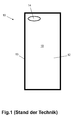
- the protection device 10 is a protective shell
- the electronic terminal 11 is a mobile phone in the form of a smartphone
- the protective device 11 is a known from the prior art solution.
- the protective device initially has a rear wall 12, which in the intended use of the protective device 10, which in FIG. 2 is shown, comes into contact with a rear side of the electronic terminal 11.
- At least one of the rear wall 12 upwardly projecting frame member 13 is provided on the side edges of the rear wall 12.
- the frame member 13 is formed as a single circumferential, continuous frame member 13.
- the rear wall 12 of the protective device 10 is a cutout 14 which cooperates with a camera of the electronic device 11 inserted into the protective device 10.
- the rear wall 12 and the frame member 13 define a receiving space 15 of the protective device 10, in which the electronic terminal 11 can be used. This is in FIG. 2 shown.
- the electronic terminal 11 is inserted into the protection device 10.
- the frame member 13 protects the side edges of the electronic terminal 11 while the bottom of the electronic terminal 11 is protected by the rear wall 12 of the protector 10 (not shown).
- the protective device 10 consists of a flexible or semi-flexible material, for example made of silicone. Rubber or plastic.
- protection devices 10 correspond in their basic structure forth in FIG. 1 shown protection device 10, so that in terms of their structure to the description FIG. 1 is referenced.
- the protective device 10 has a receiving device 20 for an NFC tag 21, and that the receiving device 20 is provided at a defined position on / in the protective device 10, such that in the connecting state of the protective device 10 with the electronic Terminal 11 (as shown in FIG FIG. 2
- an NFC tag 21 recorded in the recording device 20 has a maximum signal strength and / or a maximum signal quality and / or a maximum signal-to-noise ratio in relation to the electronic terminal 11.
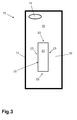
- FIG. 3 a first embodiment of a protective device 10 according to the invention is shown.
- the receiving device 20 is a receiving opening 22, which is formed in the rear wall 12 of the protective device 10. It is provided that the receiving opening 22 has a shape adapted to the contour of the male NFC tag.
- the protective device 10 in the region of the boundary 23 of the receiving opening 22 has a thickness which is greater than or equal to the thickness of the NFC tag to be inserted or inserted into the receiving opening 22.
- the NFC tag (not shown) on the electronic device (not shown) are attached or be.
- the protective device 10 with the receiving opening 22 surrounds this. This initially protects the NFC tag.
- the user is given a clear indication of where to place the NFC tag in relation to the electronic terminal. Because the After insertion of the electronic terminal into the protection device 10, the user has only the option of inserting the NFC tag into the receiving opening 22 provided in the protection device 10.
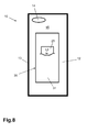
- the receiving device 20 is formed as a concave recess 24 in the rear wall 12 of the protective device 10. This is in the concave recess 24 in comparison to the receiving opening 22 from the in FIG. 3 illustrated embodiment in the protective device 10 is still a bottom 25 available, which covers the NFC tag 21 down.
- the NFC tag 21 is thus not attached to the electronic terminal itself, but is located in the protection device 10.
- the concave depression 24 is formed by the ground 25 formed by the protection device 10 and by the protection device 10 projecting from the ground 25 Side wall 26 formed.
- two fixing lugs 27 are provided for fixing the NFC tags 21 inserted into the concave recess 24 of the protective device 10.
- the fixing tabs 27 extend over the NFC tag 21 so that it is clamped in the concave recess 24 bounded by the bottom 25, the side wall 26 and the fixing tabs 27.
- the undercut 28, which is not visible from the outside, is in the FIGS. 6 and 7 shown as a dashed line.
- the concave recess 24 has a first or outwardly located first contour 29.
- An underlying or inner second contour of the concave recess 24, which forms the undercut 28 shown as a dashed line, is larger than the outer first contour 29, so that the NFC tag 21 is pressed into the concave recess 24 and on the outside lying first contour 29 of the concave recess 24, which lays over the upper surface 30 of the NFC tag 21, is clamped / is.
- the receiving device 20 is formed as a receiving pocket 31.
- the optimal location may be provided at which the NFC tag 21 is to be placed with respect to the electronic terminal (not shown).
- the basic concept of the present invention is that now the protection device 10, which is a very frequently used accessory for the electronic terminal 11, is used to optimally and safely place the NFC tag 21.
- a control device controls a handling device (not shown), which is, for example, a robot arm, to which an NFC tag 21 is arranged, the handling device in such a way that it now in different positions and orientations. 1 , 2, 3, 4 with respect to the electronic terminal 11 method.
- the method for optimizing the mounting position is implemented in the form of the language of an algorithm as follows:
- N is defined as the number of test runs to achieve test results of statistical significance.
- P is referred to as the number of NFC tag combinations of positions (eg, top, center, bottom), orientations (eg, horizontal, that is, transverse to the vertical axis of the electronic device, or vertical, that is, along the vertical axis of the electronic device); and the gap width (for example, zero mm if the NFC tag is placed directly on the back of the electronic terminal or if there is a gap of several mm).
- Q is defined as the number of different ways in which an electronic terminal is handled, for example how it is picked up, picked up and the like, and how an electronic terminal approaches an NFC reader, for example the winking motion, the speed and the distance to the NFC reader.
- T is defined as the number of different NFC readers against which the electronic terminal 11 with the NFC tag 21 is tested.
- the procedure of the method looks as follows: For each t NFC reader model (T), the following is determined: For each q possibility to handle the electronic terminal with the NFC tag (Q) and to approach the NFC reader Each p combination of NFC tag position, orientation and, if necessary, slit width (P) is determined. The whole thing is repeated N times, for example 3 times. The following can be determined:
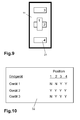
- results obtained by the method for optimizing the mounting position can be recorded in a result file 32 and stored as described in FIG. 10 is shown.
- results that have been successful are marked with a "Y”
- unsuccessful results are marked with an "N”.
Landscapes
- Engineering & Computer Science (AREA)
- Computer Networks & Wireless Communication (AREA)
- Signal Processing (AREA)
- Telephone Set Structure (AREA)
- Details Of Connecting Devices For Male And Female Coupling (AREA)
Applications Claiming Priority (1)
| Application Number | Priority Date | Filing Date | Title |
|---|---|---|---|
| DE202013105423.2U DE202013105423U1 (de) | 2013-11-28 | 2013-11-28 | Schutzvorrichtung für ein elektronisches Endgerät |
Publications (3)
| Publication Number | Publication Date |
|---|---|
| EP2878224A2 true EP2878224A2 (fr) | 2015-06-03 |
| EP2878224A3 EP2878224A3 (fr) | 2016-04-06 |
| EP2878224B1 EP2878224B1 (fr) | 2022-05-18 |
Family
ID=52000691
Family Applications (1)
| Application Number | Title | Priority Date | Filing Date |
|---|---|---|---|
| EP14195175.6A Active EP2878224B1 (fr) | 2013-11-28 | 2014-11-27 | Dispositif de protection pour un appareil électronique |
Country Status (2)
| Country | Link |
|---|---|
| EP (1) | EP2878224B1 (fr) |
| DE (1) | DE202013105423U1 (fr) |
Families Citing this family (2)
| Publication number | Priority date | Publication date | Assignee | Title |
|---|---|---|---|---|
| AT17246U1 (de) * | 2021-01-27 | 2021-10-15 | Maurer Hannes | Behälter zur Befestigung an einem Mobiltelefon |
| DE102024102646A1 (de) * | 2024-01-30 | 2025-07-31 | Tiger Media International GmbH | Schutzhülle, Hörbox und Bedienverfahren für eine Hörbox |
Citations (1)
| Publication number | Priority date | Publication date | Assignee | Title |
|---|---|---|---|---|
| DE102011107217A1 (de) | 2011-07-13 | 2013-01-17 | Giesecke & Devrient Gmbh | Transporthülle für einen Gegenstand |
Family Cites Families (5)
| Publication number | Priority date | Publication date | Assignee | Title |
|---|---|---|---|---|
| US8851386B2 (en) * | 2009-01-20 | 2014-10-07 | Mastercard International Incorporated | Removably securing small contactless payment card via removable accessory to electronic device |
| US20120168516A1 (en) * | 2010-11-29 | 2012-07-05 | Walker Bolger | Rfid transponder encapsulation for mobile electronic device covers |
| GB2492088A (en) * | 2011-06-20 | 2012-12-26 | Deborah Phillips | Shielding layer for case of mobile device to protect nearby RFID card |
| US8973795B2 (en) * | 2011-07-08 | 2015-03-10 | Herbert Chiu, Jr. | Multifunctional strap system for handheld portable electronic devices |
| KR101191867B1 (ko) * | 2012-07-04 | 2012-10-16 | 유한회사 유지피디자인 | 휴대폰 케이스 |
-
2013
- 2013-11-28 DE DE202013105423.2U patent/DE202013105423U1/de not_active Expired - Lifetime
-
2014
- 2014-11-27 EP EP14195175.6A patent/EP2878224B1/fr active Active
Patent Citations (1)
| Publication number | Priority date | Publication date | Assignee | Title |
|---|---|---|---|---|
| DE102011107217A1 (de) | 2011-07-13 | 2013-01-17 | Giesecke & Devrient Gmbh | Transporthülle für einen Gegenstand |
Also Published As
| Publication number | Publication date |
|---|---|
| EP2878224B1 (fr) | 2022-05-18 |
| DE202013105423U1 (de) | 2014-12-03 |
| EP2878224A3 (fr) | 2016-04-06 |
Similar Documents
| Publication | Publication Date | Title |
|---|---|---|
| DE60303565T2 (de) | Tragbares Informationsverarbeitungsgerät | |
| DE202010008162U1 (de) | RFID-Lesevorrichtung | |
| DE102017006450B4 (de) | RFID-Transponder für eine kontaktlose Kommunikation mit Plastikgehäuse | |
| DE102013209763A1 (de) | Berührungsbedienfeld-Aufbau, Berührungs- und Anzeigebedienfeld-Aufbau und Antennenstruktur aufweisender integrierter Berührungsanzeigebedienfeld-Aufbau und Verfahren zur Bildung eines Antennenstruktur aufweisenden Berührungsbedienfeldes | |
| DE212015000230U1 (de) | Induktive Kopplungsbaugruppe für ein elektronisches Gerät | |
| DE102011056203A1 (de) | Tragbares Gerät | |
| DE112021004803T5 (de) | Tragbare vorrichtungen mit mehreren verteilten radiofrequenzidentifikationsantennen | |
| DE102012111986A1 (de) | RFID-Lesetunnel zur Identifizierung von Objekten mittels RFID | |
| DE102015100781A1 (de) | Kapazitive-element-kopplung bei drahtloser leistung | |
| EP3776359A1 (fr) | Moyen d'identification de véhicule | |
| DE112015007110T5 (de) | Fahrzeug-Funkkommunikationsvorrichtung | |
| EP2878224B1 (fr) | Dispositif de protection pour un appareil électronique | |
| DE102017112155A1 (de) | Desense-Verringerung mittels Pin-Remap in einem modularen Gerät | |
| DE102018112570A1 (de) | Vorrichtung und Verfahren zum Senden und Empfangen von Daten eines passiven RFID-Tags | |
| DE102014019224A1 (de) | Drahtloskommunikationseinrichtung und elektronische Vorrichtung | |
| DE102022116891A1 (de) | Flexible-Struktur, Flexible-Struktur-Anordnung und Flexible- Struktur-System | |
| EP2700055B1 (fr) | Transducteur d'identification pour un système d'accès à un véhicule automobile avec un sous-ensemble nfc amovible | |
| DE102019211607B4 (de) | Messgerät mit Nahfeldantenne | |
| DE102006019690A1 (de) | Drahtlose Kommunikationsvorrichtung sowie Herstellungsverfahren hierfür | |
| EP2738715B1 (fr) | Tube Tag | |
| DE102013103144A1 (de) | Ladevorrichtung für ein mobiles Endgerät | |
| EP3046848B1 (fr) | Boîte à boisson pourvue d'une antenne pour la transmission de données | |
| DE102013203641A1 (de) | Berührungsbedienfeldstruktur und Berührungsanzeigebedienfeldstruktur mit Antennenmuster und verwandtes Kommunikationsgerät mit einer derartigen Bedienfeldstruktur | |
| EP2362329B1 (fr) | Dispositif d'augmentation des capacités de lecture/écriture d'un système RFID | |
| DE102016201253A1 (de) | Vorrichtung zur drahtlosen Energieversorgung und Datenübertragung für einen Transponder in einem rotierbaren System mit Niedrigenergieanwendungen |
Legal Events
| Date | Code | Title | Description |
|---|---|---|---|
| PUAI | Public reference made under article 153(3) epc to a published international application that has entered the european phase |
Free format text: ORIGINAL CODE: 0009012 |
|
| 17P | Request for examination filed |
Effective date: 20141127 |
|
| AK | Designated contracting states |
Kind code of ref document: A2 Designated state(s): AL AT BE BG CH CY CZ DE DK EE ES FI FR GB GR HR HU IE IS IT LI LT LU LV MC MK MT NL NO PL PT RO RS SE SI SK SM TR |
|
| AX | Request for extension of the european patent |
Extension state: BA ME |
|
| RIC1 | Information provided on ipc code assigned before grant |
Ipc: H04B 5/00 20060101ALI20151015BHEP Ipc: A45F 5/00 20060101AFI20151015BHEP Ipc: H05K 9/00 20060101ALI20151015BHEP |
|
| PUAL | Search report despatched |
Free format text: ORIGINAL CODE: 0009013 |
|
| AK | Designated contracting states |
Kind code of ref document: A3 Designated state(s): AL AT BE BG CH CY CZ DE DK EE ES FI FR GB GR HR HU IE IS IT LI LT LU LV MC MK MT NL NO PL PT RO RS SE SI SK SM TR |
|
| AX | Request for extension of the european patent |
Extension state: BA ME |
|
| RIC1 | Information provided on ipc code assigned before grant |
Ipc: H04B 5/00 20060101ALI20160229BHEP Ipc: A45F 5/00 20060101AFI20160229BHEP Ipc: H05K 9/00 20060101ALI20160229BHEP |
|
| R17P | Request for examination filed (corrected) |
Effective date: 20161006 |
|
| RBV | Designated contracting states (corrected) |
Designated state(s): AL AT BE BG CH CY CZ DE DK EE ES FI FR GB GR HR HU IE IS IT LI LT LU LV MC MK MT NL NO PL PT RO RS SE SI SK SM TR |
|
| STAA | Information on the status of an ep patent application or granted ep patent |
Free format text: STATUS: REQUEST FOR EXAMINATION WAS MADE |
|
| STAA | Information on the status of an ep patent application or granted ep patent |
Free format text: STATUS: EXAMINATION IS IN PROGRESS |
|
| 17Q | First examination report despatched |
Effective date: 20180309 |
|
| GRAP | Despatch of communication of intention to grant a patent |
Free format text: ORIGINAL CODE: EPIDOSNIGR1 |
|
| STAA | Information on the status of an ep patent application or granted ep patent |
Free format text: STATUS: GRANT OF PATENT IS INTENDED |
|
| INTG | Intention to grant announced |
Effective date: 20211210 |
|
| GRAS | Grant fee paid |
Free format text: ORIGINAL CODE: EPIDOSNIGR3 |
|
| GRAA | (expected) grant |
Free format text: ORIGINAL CODE: 0009210 |
|
| STAA | Information on the status of an ep patent application or granted ep patent |
Free format text: STATUS: THE PATENT HAS BEEN GRANTED |
|
| AK | Designated contracting states |
Kind code of ref document: B1 Designated state(s): AL AT BE BG CH CY CZ DE DK EE ES FI FR GB GR HR HU IE IS IT LI LT LU LV MC MK MT NL NO PL PT RO RS SE SI SK SM TR |
|
| REG | Reference to a national code |
Ref country code: GB Ref legal event code: FG4D Free format text: NOT ENGLISH |
|
| REG | Reference to a national code |
Ref country code: CH Ref legal event code: EP |
|
| REG | Reference to a national code |
Ref country code: IE Ref legal event code: FG4D Free format text: LANGUAGE OF EP DOCUMENT: GERMAN |
|
| REG | Reference to a national code |
Ref country code: DE Ref legal event code: R096 Ref document number: 502014016254 Country of ref document: DE |
|
| REG | Reference to a national code |
Ref country code: AT Ref legal event code: REF Ref document number: 1492663 Country of ref document: AT Kind code of ref document: T Effective date: 20220615 |
|
| REG | Reference to a national code |
Ref country code: LT Ref legal event code: MG9D |
|
| REG | Reference to a national code |
Ref country code: NL Ref legal event code: MP Effective date: 20220518 |
|
| PG25 | Lapsed in a contracting state [announced via postgrant information from national office to epo] |
Ref country code: SE Free format text: LAPSE BECAUSE OF FAILURE TO SUBMIT A TRANSLATION OF THE DESCRIPTION OR TO PAY THE FEE WITHIN THE PRESCRIBED TIME-LIMIT Effective date: 20220518 Ref country code: PT Free format text: LAPSE BECAUSE OF FAILURE TO SUBMIT A TRANSLATION OF THE DESCRIPTION OR TO PAY THE FEE WITHIN THE PRESCRIBED TIME-LIMIT Effective date: 20220919 Ref country code: NO Free format text: LAPSE BECAUSE OF FAILURE TO SUBMIT A TRANSLATION OF THE DESCRIPTION OR TO PAY THE FEE WITHIN THE PRESCRIBED TIME-LIMIT Effective date: 20220818 Ref country code: NL Free format text: LAPSE BECAUSE OF FAILURE TO SUBMIT A TRANSLATION OF THE DESCRIPTION OR TO PAY THE FEE WITHIN THE PRESCRIBED TIME-LIMIT Effective date: 20220518 Ref country code: LT Free format text: LAPSE BECAUSE OF FAILURE TO SUBMIT A TRANSLATION OF THE DESCRIPTION OR TO PAY THE FEE WITHIN THE PRESCRIBED TIME-LIMIT Effective date: 20220518 Ref country code: HR Free format text: LAPSE BECAUSE OF FAILURE TO SUBMIT A TRANSLATION OF THE DESCRIPTION OR TO PAY THE FEE WITHIN THE PRESCRIBED TIME-LIMIT Effective date: 20220518 Ref country code: GR Free format text: LAPSE BECAUSE OF FAILURE TO SUBMIT A TRANSLATION OF THE DESCRIPTION OR TO PAY THE FEE WITHIN THE PRESCRIBED TIME-LIMIT Effective date: 20220819 Ref country code: FI Free format text: LAPSE BECAUSE OF FAILURE TO SUBMIT A TRANSLATION OF THE DESCRIPTION OR TO PAY THE FEE WITHIN THE PRESCRIBED TIME-LIMIT Effective date: 20220518 Ref country code: ES Free format text: LAPSE BECAUSE OF FAILURE TO SUBMIT A TRANSLATION OF THE DESCRIPTION OR TO PAY THE FEE WITHIN THE PRESCRIBED TIME-LIMIT Effective date: 20220518 Ref country code: BG Free format text: LAPSE BECAUSE OF FAILURE TO SUBMIT A TRANSLATION OF THE DESCRIPTION OR TO PAY THE FEE WITHIN THE PRESCRIBED TIME-LIMIT Effective date: 20220818 |
|
| PG25 | Lapsed in a contracting state [announced via postgrant information from national office to epo] |
Ref country code: RS Free format text: LAPSE BECAUSE OF FAILURE TO SUBMIT A TRANSLATION OF THE DESCRIPTION OR TO PAY THE FEE WITHIN THE PRESCRIBED TIME-LIMIT Effective date: 20220518 Ref country code: PL Free format text: LAPSE BECAUSE OF FAILURE TO SUBMIT A TRANSLATION OF THE DESCRIPTION OR TO PAY THE FEE WITHIN THE PRESCRIBED TIME-LIMIT Effective date: 20220518 Ref country code: LV Free format text: LAPSE BECAUSE OF FAILURE TO SUBMIT A TRANSLATION OF THE DESCRIPTION OR TO PAY THE FEE WITHIN THE PRESCRIBED TIME-LIMIT Effective date: 20220518 Ref country code: IS Free format text: LAPSE BECAUSE OF FAILURE TO SUBMIT A TRANSLATION OF THE DESCRIPTION OR TO PAY THE FEE WITHIN THE PRESCRIBED TIME-LIMIT Effective date: 20220918 |
|
| PG25 | Lapsed in a contracting state [announced via postgrant information from national office to epo] |
Ref country code: SM Free format text: LAPSE BECAUSE OF FAILURE TO SUBMIT A TRANSLATION OF THE DESCRIPTION OR TO PAY THE FEE WITHIN THE PRESCRIBED TIME-LIMIT Effective date: 20220518 Ref country code: SK Free format text: LAPSE BECAUSE OF FAILURE TO SUBMIT A TRANSLATION OF THE DESCRIPTION OR TO PAY THE FEE WITHIN THE PRESCRIBED TIME-LIMIT Effective date: 20220518 Ref country code: RO Free format text: LAPSE BECAUSE OF FAILURE TO SUBMIT A TRANSLATION OF THE DESCRIPTION OR TO PAY THE FEE WITHIN THE PRESCRIBED TIME-LIMIT Effective date: 20220518 Ref country code: EE Free format text: LAPSE BECAUSE OF FAILURE TO SUBMIT A TRANSLATION OF THE DESCRIPTION OR TO PAY THE FEE WITHIN THE PRESCRIBED TIME-LIMIT Effective date: 20220518 Ref country code: DK Free format text: LAPSE BECAUSE OF FAILURE TO SUBMIT A TRANSLATION OF THE DESCRIPTION OR TO PAY THE FEE WITHIN THE PRESCRIBED TIME-LIMIT Effective date: 20220518 Ref country code: CZ Free format text: LAPSE BECAUSE OF FAILURE TO SUBMIT A TRANSLATION OF THE DESCRIPTION OR TO PAY THE FEE WITHIN THE PRESCRIBED TIME-LIMIT Effective date: 20220518 |
|
| REG | Reference to a national code |
Ref country code: DE Ref legal event code: R097 Ref document number: 502014016254 Country of ref document: DE |
|
| PLBE | No opposition filed within time limit |
Free format text: ORIGINAL CODE: 0009261 |
|
| STAA | Information on the status of an ep patent application or granted ep patent |
Free format text: STATUS: NO OPPOSITION FILED WITHIN TIME LIMIT |
|
| PG25 | Lapsed in a contracting state [announced via postgrant information from national office to epo] |
Ref country code: AL Free format text: LAPSE BECAUSE OF FAILURE TO SUBMIT A TRANSLATION OF THE DESCRIPTION OR TO PAY THE FEE WITHIN THE PRESCRIBED TIME-LIMIT Effective date: 20220518 |
|
| 26N | No opposition filed |
Effective date: 20230221 |
|
| PG25 | Lapsed in a contracting state [announced via postgrant information from national office to epo] |
Ref country code: SI Free format text: LAPSE BECAUSE OF FAILURE TO SUBMIT A TRANSLATION OF THE DESCRIPTION OR TO PAY THE FEE WITHIN THE PRESCRIBED TIME-LIMIT Effective date: 20220518 |
|
| PG25 | Lapsed in a contracting state [announced via postgrant information from national office to epo] |
Ref country code: MC Free format text: LAPSE BECAUSE OF FAILURE TO SUBMIT A TRANSLATION OF THE DESCRIPTION OR TO PAY THE FEE WITHIN THE PRESCRIBED TIME-LIMIT Effective date: 20220518 |
|
| REG | Reference to a national code |
Ref country code: CH Ref legal event code: PL |
|
| REG | Reference to a national code |
Ref country code: BE Ref legal event code: MM Effective date: 20221130 |
|
| PG25 | Lapsed in a contracting state [announced via postgrant information from national office to epo] |
Ref country code: LI Free format text: LAPSE BECAUSE OF NON-PAYMENT OF DUE FEES Effective date: 20221130 Ref country code: CH Free format text: LAPSE BECAUSE OF NON-PAYMENT OF DUE FEES Effective date: 20221130 |
|
| PG25 | Lapsed in a contracting state [announced via postgrant information from national office to epo] |
Ref country code: LU Free format text: LAPSE BECAUSE OF NON-PAYMENT OF DUE FEES Effective date: 20221127 |
|
| PG25 | Lapsed in a contracting state [announced via postgrant information from national office to epo] |
Ref country code: IE Free format text: LAPSE BECAUSE OF NON-PAYMENT OF DUE FEES Effective date: 20221127 |
|
| PG25 | Lapsed in a contracting state [announced via postgrant information from national office to epo] |
Ref country code: BE Free format text: LAPSE BECAUSE OF NON-PAYMENT OF DUE FEES Effective date: 20221130 |
|
| REG | Reference to a national code |
Ref country code: AT Ref legal event code: MM01 Ref document number: 1492663 Country of ref document: AT Kind code of ref document: T Effective date: 20221127 |
|
| PG25 | Lapsed in a contracting state [announced via postgrant information from national office to epo] |
Ref country code: IT Free format text: LAPSE BECAUSE OF FAILURE TO SUBMIT A TRANSLATION OF THE DESCRIPTION OR TO PAY THE FEE WITHIN THE PRESCRIBED TIME-LIMIT Effective date: 20220518 Ref country code: AT Free format text: LAPSE BECAUSE OF NON-PAYMENT OF DUE FEES Effective date: 20221127 |
|
| PG25 | Lapsed in a contracting state [announced via postgrant information from national office to epo] |
Ref country code: HU Free format text: LAPSE BECAUSE OF FAILURE TO SUBMIT A TRANSLATION OF THE DESCRIPTION OR TO PAY THE FEE WITHIN THE PRESCRIBED TIME-LIMIT; INVALID AB INITIO Effective date: 20141127 |
|
| PG25 | Lapsed in a contracting state [announced via postgrant information from national office to epo] |
Ref country code: CY Free format text: LAPSE BECAUSE OF FAILURE TO SUBMIT A TRANSLATION OF THE DESCRIPTION OR TO PAY THE FEE WITHIN THE PRESCRIBED TIME-LIMIT Effective date: 20220511 |
|
| PG25 | Lapsed in a contracting state [announced via postgrant information from national office to epo] |
Ref country code: MK Free format text: LAPSE BECAUSE OF FAILURE TO SUBMIT A TRANSLATION OF THE DESCRIPTION OR TO PAY THE FEE WITHIN THE PRESCRIBED TIME-LIMIT Effective date: 20220511 |
|
| PG25 | Lapsed in a contracting state [announced via postgrant information from national office to epo] |
Ref country code: TR Free format text: LAPSE BECAUSE OF FAILURE TO SUBMIT A TRANSLATION OF THE DESCRIPTION OR TO PAY THE FEE WITHIN THE PRESCRIBED TIME-LIMIT Effective date: 20220511 |
|
| PG25 | Lapsed in a contracting state [announced via postgrant information from national office to epo] |
Ref country code: MT Free format text: LAPSE BECAUSE OF FAILURE TO SUBMIT A TRANSLATION OF THE DESCRIPTION OR TO PAY THE FEE WITHIN THE PRESCRIBED TIME-LIMIT Effective date: 20220511 |
|
| PG25 | Lapsed in a contracting state [announced via postgrant information from national office to epo] |
Ref country code: BG Free format text: LAPSE BECAUSE OF FAILURE TO SUBMIT A TRANSLATION OF THE DESCRIPTION OR TO PAY THE FEE WITHIN THE PRESCRIBED TIME-LIMIT Effective date: 20220518 |
|
| PG25 | Lapsed in a contracting state [announced via postgrant information from national office to epo] |
Ref country code: BG Free format text: LAPSE BECAUSE OF FAILURE TO SUBMIT A TRANSLATION OF THE DESCRIPTION OR TO PAY THE FEE WITHIN THE PRESCRIBED TIME-LIMIT Effective date: 20220518 |
|
| PGFP | Annual fee paid to national office [announced via postgrant information from national office to epo] |
Ref country code: DE Payment date: 20251119 Year of fee payment: 12 |
|
| PGFP | Annual fee paid to national office [announced via postgrant information from national office to epo] |
Ref country code: GB Payment date: 20251121 Year of fee payment: 12 |
|
| PGFP | Annual fee paid to national office [announced via postgrant information from national office to epo] |
Ref country code: FR Payment date: 20251125 Year of fee payment: 12 |