EP2878364A1 - Installation et procédé correspondant d'application à chaud d'une composition adhésive - Google Patents
Installation et procédé correspondant d'application à chaud d'une composition adhésive Download PDFInfo
- Publication number
- EP2878364A1 EP2878364A1 EP14195521.1A EP14195521A EP2878364A1 EP 2878364 A1 EP2878364 A1 EP 2878364A1 EP 14195521 A EP14195521 A EP 14195521A EP 2878364 A1 EP2878364 A1 EP 2878364A1
- Authority
- EP
- European Patent Office
- Prior art keywords
- adhesive composition
- application
- temperature
- heating device
- installation
- Prior art date
- Legal status (The legal status is an assumption and is not a legal conclusion. Google has not performed a legal analysis and makes no representation as to the accuracy of the status listed.)
- Granted
Links
- 239000000203 mixture Substances 0.000 title claims abstract description 189
- 239000000853 adhesive Substances 0.000 title claims abstract description 168
- 230000001070 adhesive effect Effects 0.000 title claims abstract description 168
- 238000009434 installation Methods 0.000 title claims abstract description 46
- 238000000034 method Methods 0.000 title claims abstract description 24
- 230000008569 process Effects 0.000 title claims description 4
- 238000010438 heat treatment Methods 0.000 claims abstract description 92
- 230000003068 static effect Effects 0.000 claims abstract description 33
- 239000004020 conductor Substances 0.000 claims abstract description 15
- 239000012530 fluid Substances 0.000 claims abstract description 12
- 238000004132 cross linking Methods 0.000 claims description 28
- 238000002156 mixing Methods 0.000 claims description 23
- 238000003860 storage Methods 0.000 claims description 20
- 238000005086 pumping Methods 0.000 claims description 9
- 239000012777 electrically insulating material Substances 0.000 claims description 4
- 239000011231 conductive filler Substances 0.000 claims description 3
- 239000011521 glass Substances 0.000 claims description 3
- 229920000642 polymer Polymers 0.000 claims description 3
- 238000007731 hot pressing Methods 0.000 claims description 2
- 241000196324 Embryophyta Species 0.000 claims 2
- 240000001140 Mimosa pudica Species 0.000 claims 1
- 230000006698 induction Effects 0.000 description 10
- 238000006243 chemical reaction Methods 0.000 description 8
- 238000002844 melting Methods 0.000 description 7
- 230000008018 melting Effects 0.000 description 7
- 239000000463 material Substances 0.000 description 5
- 239000007787 solid Substances 0.000 description 4
- 230000000694 effects Effects 0.000 description 3
- 238000004519 manufacturing process Methods 0.000 description 3
- 239000004820 Pressure-sensitive adhesive Substances 0.000 description 2
- 239000003054 catalyst Substances 0.000 description 2
- 239000011810 insulating material Substances 0.000 description 2
- 230000035515 penetration Effects 0.000 description 2
- 230000035699 permeability Effects 0.000 description 2
- 239000011347 resin Substances 0.000 description 2
- 229920005989 resin Polymers 0.000 description 2
- 238000011144 upstream manufacturing Methods 0.000 description 2
- 239000004822 Hot adhesive Substances 0.000 description 1
- 239000004831 Hot glue Substances 0.000 description 1
- 239000004721 Polyphenylene oxide Substances 0.000 description 1
- 239000004823 Reactive adhesive Substances 0.000 description 1
- 241001639412 Verres Species 0.000 description 1
- 230000015572 biosynthetic process Effects 0.000 description 1
- 230000000903 blocking effect Effects 0.000 description 1
- 230000008859 change Effects 0.000 description 1
- 239000011248 coating agent Substances 0.000 description 1
- 238000000576 coating method Methods 0.000 description 1
- 238000004891 communication Methods 0.000 description 1
- 238000006073 displacement reaction Methods 0.000 description 1
- 230000004927 fusion Effects 0.000 description 1
- 238000007429 general method Methods 0.000 description 1
- 230000020169 heat generation Effects 0.000 description 1
- 239000008240 homogeneous mixture Substances 0.000 description 1
- 230000001939 inductive effect Effects 0.000 description 1
- 238000002347 injection Methods 0.000 description 1
- 239000007924 injection Substances 0.000 description 1
- 238000001746 injection moulding Methods 0.000 description 1
- 238000009413 insulation Methods 0.000 description 1
- 239000003973 paint Substances 0.000 description 1
- 229920006267 polyester film Polymers 0.000 description 1
- 229920000570 polyether Polymers 0.000 description 1
- 229920002635 polyurethane Polymers 0.000 description 1
- 239000004814 polyurethane Substances 0.000 description 1
- 230000009467 reduction Effects 0.000 description 1
- 230000003014 reinforcing effect Effects 0.000 description 1
- 238000004513 sizing Methods 0.000 description 1
Images

Classifications
-
- B—PERFORMING OPERATIONS; TRANSPORTING
- B05—SPRAYING OR ATOMISING IN GENERAL; APPLYING FLUENT MATERIALS TO SURFACES, IN GENERAL
- B05C—APPARATUS FOR APPLYING FLUENT MATERIALS TO SURFACES, IN GENERAL
- B05C11/00—Component parts, details or accessories not specifically provided for in groups B05C1/00 - B05C9/00
- B05C11/10—Storage, supply or control of liquid or other fluent material; Recovery of excess liquid or other fluent material
- B05C11/1042—Storage, supply or control of liquid or other fluent material; Recovery of excess liquid or other fluent material provided with means for heating or cooling the liquid or other fluent material in the supplying means upstream of the applying apparatus
-
- C—CHEMISTRY; METALLURGY
- C09—DYES; PAINTS; POLISHES; NATURAL RESINS; ADHESIVES; COMPOSITIONS NOT OTHERWISE PROVIDED FOR; APPLICATIONS OF MATERIALS NOT OTHERWISE PROVIDED FOR
- C09J—ADHESIVES; NON-MECHANICAL ASPECTS OF ADHESIVE PROCESSES IN GENERAL; ADHESIVE PROCESSES NOT PROVIDED FOR ELSEWHERE; USE OF MATERIALS AS ADHESIVES
- C09J5/00—Adhesive processes in general; Adhesive processes not provided for elsewhere, e.g. relating to primers
- C09J5/06—Adhesive processes in general; Adhesive processes not provided for elsewhere, e.g. relating to primers involving heating of the applied adhesive
-
- B—PERFORMING OPERATIONS; TRANSPORTING
- B01—PHYSICAL OR CHEMICAL PROCESSES OR APPARATUS IN GENERAL
- B01F—MIXING, e.g. DISSOLVING, EMULSIFYING OR DISPERSING
- B01F23/00—Mixing according to the phases to be mixed, e.g. dispersing or emulsifying
- B01F23/80—After-treatment of the mixture
- B01F23/811—Heating the mixture
-
- B—PERFORMING OPERATIONS; TRANSPORTING
- B01—PHYSICAL OR CHEMICAL PROCESSES OR APPARATUS IN GENERAL
- B01F—MIXING, e.g. DISSOLVING, EMULSIFYING OR DISPERSING
- B01F25/00—Flow mixers; Mixers for falling materials, e.g. solid particles
- B01F25/40—Static mixers
- B01F25/42—Static mixers in which the mixing is affected by moving the components jointly in changing directions, e.g. in tubes provided with baffles or obstructions
- B01F25/43—Mixing tubes, e.g. wherein the material is moved in a radial or partly reversed direction
- B01F25/431—Straight mixing tubes with baffles or obstructions that do not cause substantial pressure drop; Baffles therefor
- B01F25/4316—Straight mixing tubes with baffles or obstructions that do not cause substantial pressure drop; Baffles therefor the baffles being flat pieces of material, e.g. intermeshing, fixed to the wall or fixed on a central rod
- B01F25/43161—Straight mixing tubes with baffles or obstructions that do not cause substantial pressure drop; Baffles therefor the baffles being flat pieces of material, e.g. intermeshing, fixed to the wall or fixed on a central rod composed of consecutive sections of flat pieces of material
-
- B—PERFORMING OPERATIONS; TRANSPORTING
- B01—PHYSICAL OR CHEMICAL PROCESSES OR APPARATUS IN GENERAL
- B01F—MIXING, e.g. DISSOLVING, EMULSIFYING OR DISPERSING
- B01F35/00—Accessories for mixers; Auxiliary operations or auxiliary devices; Parts or details of general application
- B01F35/90—Heating or cooling systems
- B01F35/92—Heating or cooling systems for heating the outside of the receptacle, e.g. heated jackets or burners
-
- B—PERFORMING OPERATIONS; TRANSPORTING
- B01—PHYSICAL OR CHEMICAL PROCESSES OR APPARATUS IN GENERAL
- B01F—MIXING, e.g. DISSOLVING, EMULSIFYING OR DISPERSING
- B01F35/00—Accessories for mixers; Auxiliary operations or auxiliary devices; Parts or details of general application
- B01F35/90—Heating or cooling systems
- B01F35/95—Heating or cooling systems using heated or cooled stirrers
-
- B—PERFORMING OPERATIONS; TRANSPORTING
- B05—SPRAYING OR ATOMISING IN GENERAL; APPLYING FLUENT MATERIALS TO SURFACES, IN GENERAL
- B05B—SPRAYING APPARATUS; ATOMISING APPARATUS; NOZZLES
- B05B1/00—Nozzles, spray heads or other outlets, with or without auxiliary devices such as valves, heating means
- B05B1/24—Nozzles, spray heads or other outlets, with or without auxiliary devices such as valves, heating means incorporating means for heating the liquid or other fluent material, e.g. electrically
-
- B—PERFORMING OPERATIONS; TRANSPORTING
- B05—SPRAYING OR ATOMISING IN GENERAL; APPLYING FLUENT MATERIALS TO SURFACES, IN GENERAL
- B05B—SPRAYING APPARATUS; ATOMISING APPARATUS; NOZZLES
- B05B7/00—Spraying apparatus for discharge of liquids or other fluent materials from two or more sources, e.g. of liquid and air, of powder and gas
- B05B7/16—Spraying apparatus for discharge of liquids or other fluent materials from two or more sources, e.g. of liquid and air, of powder and gas incorporating means for heating or cooling the material to be sprayed
-
- B—PERFORMING OPERATIONS; TRANSPORTING
- B05—SPRAYING OR ATOMISING IN GENERAL; APPLYING FLUENT MATERIALS TO SURFACES, IN GENERAL
- B05D—PROCESSES FOR APPLYING FLUENT MATERIALS TO SURFACES, IN GENERAL
- B05D1/00—Processes for applying liquids or other fluent materials
- B05D1/02—Processes for applying liquids or other fluent materials performed by spraying
-
- B—PERFORMING OPERATIONS; TRANSPORTING
- B05—SPRAYING OR ATOMISING IN GENERAL; APPLYING FLUENT MATERIALS TO SURFACES, IN GENERAL
- B05D—PROCESSES FOR APPLYING FLUENT MATERIALS TO SURFACES, IN GENERAL
- B05D1/00—Processes for applying liquids or other fluent materials
- B05D1/26—Processes for applying liquids or other fluent materials performed by applying the liquid or other fluent material from an outlet device in contact with, or almost in contact with, the surface
-
- B—PERFORMING OPERATIONS; TRANSPORTING
- B05—SPRAYING OR ATOMISING IN GENERAL; APPLYING FLUENT MATERIALS TO SURFACES, IN GENERAL
- B05D—PROCESSES FOR APPLYING FLUENT MATERIALS TO SURFACES, IN GENERAL
- B05D5/00—Processes for applying liquids or other fluent materials to surfaces to obtain special surface effects, finishes or structures
- B05D5/10—Processes for applying liquids or other fluent materials to surfaces to obtain special surface effects, finishes or structures to obtain an adhesive surface
-
- B—PERFORMING OPERATIONS; TRANSPORTING
- B29—WORKING OF PLASTICS; WORKING OF SUBSTANCES IN A PLASTIC STATE IN GENERAL
- B29B—PREPARATION OR PRETREATMENT OF THE MATERIAL TO BE SHAPED; MAKING GRANULES OR PREFORMS; RECOVERY OF PLASTICS OR OTHER CONSTITUENTS OF WASTE MATERIAL CONTAINING PLASTICS
- B29B13/00—Conditioning or physical treatment of the material to be shaped
- B29B13/02—Conditioning or physical treatment of the material to be shaped by heating
- B29B13/022—Melting the material to be shaped
-
- B—PERFORMING OPERATIONS; TRANSPORTING
- B01—PHYSICAL OR CHEMICAL PROCESSES OR APPARATUS IN GENERAL
- B01F—MIXING, e.g. DISSOLVING, EMULSIFYING OR DISPERSING
- B01F35/00—Accessories for mixers; Auxiliary operations or auxiliary devices; Parts or details of general application
- B01F35/90—Heating or cooling systems
- B01F2035/99—Heating
-
- B—PERFORMING OPERATIONS; TRANSPORTING
- B05—SPRAYING OR ATOMISING IN GENERAL; APPLYING FLUENT MATERIALS TO SURFACES, IN GENERAL
- B05B—SPRAYING APPARATUS; ATOMISING APPARATUS; NOZZLES
- B05B15/00—Details of spraying plant or spraying apparatus not otherwise provided for; Accessories
- B05B15/20—Arrangements for agitating the material to be sprayed, e.g. for stirring, mixing or homogenising
-
- B—PERFORMING OPERATIONS; TRANSPORTING
- B05—SPRAYING OR ATOMISING IN GENERAL; APPLYING FLUENT MATERIALS TO SURFACES, IN GENERAL
- B05C—APPARATUS FOR APPLYING FLUENT MATERIALS TO SURFACES, IN GENERAL
- B05C5/00—Apparatus in which liquid or other fluent material is projected, poured or allowed to flow on to the surface of the work
- B05C5/02—Apparatus in which liquid or other fluent material is projected, poured or allowed to flow on to the surface of the work the liquid or other fluent material being discharged through an outlet orifice by pressure, e.g. from an outlet device in contact or almost in contact, with the work
- B05C5/0254—Coating heads with slot-shaped outlet
Definitions
- the invention relates to a hot application installation of an adhesive composition comprising an in-line heating device and a corresponding method for hot application of the adhesive composition.
- FIG. 1 shows a plant 100 according to the prior art of hot application of an adhesive composition 80.
- This installation 100 comprises a reservoir 82 for storing the adhesive composition 80, here in the form of a 200 liter drum.
- the adhesive composition 80 is intended to be applied on a surface 96, here a polyester film running on a cylinder 92 of axis 94.
- This application is performed using a nozzle 90 of sizing to form an adhesive surface 98.
- the feeding of the adhesive composition nozzle 80 to be applied is carried out using a line 88 for fluidic communication of the adhesive composition between the barrel and the nozzle 90, the line 88 being provided with a pump 86 circulation of the adhesive composition.
- the adhesive composition 80 which can be solid at room temperature, is for example heated to a temperature of 100 ° C. to 180 ° C. C to have sufficient viscosity.
- the installation 100 then comprises a heating means 84 upstream of the pump 86.
- the heating means 84 corresponds, for example, to a melting plate brought into contact with the adhesive composition in the drum. This melting plate is electrically heated by heating resistors.
- the quantity of heat communicated from the heating means 84 to the adhesive composition 80 depends in particular on the exchange surface between the heating means 84 and the adhesive composition 80.
- Figures 2, 3 and 4 different variants of the melting plate can then be envisaged, respectively a variant 70 with smooth exchange surface 76 and variants 72 and 74 with exchange surfaces having fins 78.
- the adhesive composition 80 to be applied comprises a reactive prepolymer and has an application temperature of, for example, 100 to 120 ° C., which is too close to a temperature range of crosslinking, from 100 ° C to 140 ° C for example.
- an adhesive composition 80 heated in the storage tank 82 with a target heating temperature greater than or equal to 100 ° C begins to crosslink, and a fortiori in the presence of moisture.
- the residence time of the adhesive composition 80 at 100.degree. poorly controlled and on the other hand the temperature actually applied is also poorly controlled.
- Such a cross-linked block is capable of blocking the melting plate 72 or 74 and preventing any flow of adhesive composition 80 fluid up to the application nozzle 90.
- This risk of fouling of the melting plate 72 or 74 is particularly aggravated for adhesive compositions crosslinking with moisture. Indeed, each drum change exposes the residues of adhesive compositions on the plate at the humidity of the air then reinforcing the crosslinking of these residues on the plate.
- the invention aims to provide an installation and a method of applying such an adhesive composition.
- the adhesive composition is applied with a viscosity of 15 Pa.s ⁇ 5 Pa.s.
- the adhesive composition is applied at a temperature of between 50 ° C. and 140 °, preferably between 80 ° C. and 120 ° C., more preferably between 100 ° C. and 110 ° C. ° C.
- This crosslinked adhesive composition may correspond to a pressure-sensitive adhesive composition (also known in English as “ pressure sensitive adhesive " abbreviated as " PSA ").
- FIG 5 shows a schematic representation of one embodiment of the proposed facility.
- Figures 1 and 5 have the same reference signs.
- the proposed installation differs in particular from the installation 100 of the figure 1 in that it comprises in line 88 a heating device 22.
- the heating device 22 contributes to the application temperature of the adhesive composition 80.
- the application temperature corresponds to a temperature where the adhesive composition to be applied has a sufficiently low viscosity to allow the application, that is to say the coating, the adhesive composition 80 on the surface 96.
- An application temperature of the adhesive composition 80 can thus correspond to a temperature where the viscosity of the adhesive composition is less than or equal to 20 Pa.s, preferably less than or equal to at 10 Pa.s.
- the adhesive composition 80 may have a viscosity of 15 ⁇ 5 Pa.s at an application temperature of 100 ° C to 120 ° C.
- the heating device 22 is distinguished by being disposed in line 88.
- the heating device 22 performs the heating of the adhesive composition 80 when the adhesive composition 80 is in motion.
- This heating in motion also called in-line heating, makes it possible to reduce the hot residence time of the adhesive composition 80 with respect to a heating of the adhesive composition 80 in the storage tank 82 where the adhesive composition 80 when hot is almost motionless.
- the in-line heating device 22 can effect the application temperature of the adhesive composition 80, even in the case where the application temperature is included. in the crosslinking temperature range of the adhesive composition 80. Indeed, depending on the intended application temperature included in the crosslinking temperature range, the hot residence time of the moving adhesive composition 80 can be adapted.
- the hot residence time of the moving adhesive composition may in particular be modulated with the flow rate of the adhesive composition 80 and the line displacement 88 between the in-line heating device 22 and the application nozzle 50.
- the flow rate of the In-line adhesive composition 80 can be adjusted so that the crosslinking reaction is limited so as not to foul the installation with crosslinked adhesive composition.
- the flow rate of the in-line adhesive composition 80 can thus be adjusted so that, depending on the reaction kinetics and on the temperature, in particular in the static mixer, the conversion rate of the crosslinking reaction of the adhesive composition remains lower or lower. equal to 30%, preferably less than or equal to 10%.
- the flow rate of the adhesive composition 80 in the on-line heating device is for example between 80 gs -1 and 170 gs -1 , ie about 5 to 10 kg per minute, such as equal to 120 g.s -1 , or about 7 kg per minute.
- the in-line heating device 22 has a structure adapted to a very efficient heating.
- the figure 6 shows a longitudinal sectional view of an embodiment of the in-line heating device 22.
- the in-line heating device 22 comprises induction heating.
- the in-line heating device 22 comprises an inductor cable 26, here in the form of a solenoid, to allow the generation of a magnetic field.
- the in-line heating device 22 further comprises a static mixer 30 in which the adhesive composition to be heated 80 can circulate.
- Static mixers are particularly known for use in the injection molding industry to homogenize the material before injection into a mold.
- Static mixers known in the art include mixing elements having fluid deflection surfaces for achieving a homogeneous mixture of fluid over a short distance and with low shear.
- the static mixer 30 included in the in-line heating device 22 comprises at least one such mixing element 38.
- the static mixer has a set of mixing elements 38 arranged in a sheath 34.
- the sheath 34 forms a circulation duct of the adhesive composition 80.
- the sheath 34 and the at least one mixing element 38 constitute the static mixer 30 of the in-line heating device 22.
- the sheath 34 as a circulation duct is a portion of the line 88.
- the static heat exchanger 30 formed in the proposed heating device 22 has the particularity of having an electrically conductive material.
- an electrically conductive material is understood to mean a material having a resistivity of less than 10 ⁇ .m, preferably less than 10 -6 ⁇ .m.
- the magnetic field generated by the inductor cable 26 surrounding the static mixer 30 is then capable of inducing an electric current, known as an eddy current, into the electrical conductor of the static mixer 30.
- the eddy currents induced in the conductor electric cause Joule heat generation which diffuses to the adhesive composition 80 via the components of the static mixer 30.
- the efficiency of the heat exchange of the heat generated between the static mixer 30 and the adhesive composition 80 depends on the structure of the sheath and, in particular, the mixing elements 38 and their useful surface of heat exchange.
- the figure 7 shows an embodiment of one of the mixing elements 38 of the in-line heating device 22.
- the mixing element 38 has deflection surfaces 32 which form different angles with respect to the main direction 28 of circulation of the adhesive composition 80 in the static mixer 30.
- This mixing element 38 having these deflection surfaces then has a high surface density in contact with the adhesive composition 80 to be mixed.
- the surface density corresponds to a quantity of exchange surfaces per volume and is therefore expressed in m 2 / m 3 , ie in m -1 .
- the mixing elements 38 included in the in-line heating device 22 may have a surface density greater than or equal to 5 * 10 3 m -1 , preferably between 5 * 10 3 m -1 and 10 * 10 3 m -1 .
- Such surface densities correspond, for example, to a static mixer 40 to 60 cm long for a diameter of 4 to 6 cm and with a useful surface area of 5 to 10 m 2 .
- a high surface density makes it possible to obtain a large useful surface of heat exchange between the static mixer 30 and the circulating adhesive composition 80.
- the deflection surfaces 32 form a structure-type heat exchanger suitable for rapid application temperature setting of the adhesive composition 80 present in the sheath 34.
- the installation 20 may comprise a recirculation of the adhesive composition in the on-line heating device 22.
- This recirculation may include a downstream connection of the in-line heating device 22 which returns the adhesive composition upstream of the in-line heating device 22, for example by means of a circulation pump.
- Such recirculation makes it possible to increase the residence time of the adhesive composition in the on-line heating device 22 without reducing the flow rate of the installation 80 and without increasing the dimensions of the static mixer.
- such a recirculation facilitates the rise in temperature of the installation during a restart, by allowing the circulation of the adhesive composition in the circuit formed by the recirculation and the on-line heating device 22 as long as the heating device online 22 has not yet reached the desired temperature.
- the in-line heating device 22 allows the adhesive composition to be brought to temperature at the application temperature with a short time. stay.
- the hot application installation 20 with the application nozzle 50, the nozzle supply line 88 and the in-line heating device 22 can thus apply adhesive compositions 80 to the surface 96.
- the application installation 20 is also proposed with the storage tank 82 comprising the adhesive composition 80 to be applied and connected to the supply line 88 of the nozzle 50. It is furthermore proposed a method of hot application of an adhesive composition comprising the provision of such an application installation 20.
- the adhesive composition flows from the storage tank to the on-line heating device, for example by means of a heat pump. Circulation 46.
- the adhesive composition 80 is then heated in line with the aid of the heating device 22 because of the electrical supply of the inductor cable 26.
- the inductor cable 26 is for example supplied with the aid of an electric current at high frequency, preferably greater than or equal to 1 MHz, such as 15 MHz.
- the adhesive composition 80 is applied to the surface 96 by the application nozzle 50.
- the application can be carried out with a fluid viscosity of 15 Pa. s ⁇ 5 Pa.s.
- the application temperature can be between 50 ° C and 140 ° C. More particularly, the application temperature may be between 80 ° C. and 120 ° C. or between 100 ° C. and 110 ° C.
- the proposed method of application is particularly advantageous when it is part of a more general method of producing a crosslinked adhesive carrier.
- Such a process for producing a crosslinked adhesive support is particularly proposed.
- the surface 96 is provided to support the application of the adhesive composition 80 according to the previously described hot application method.
- the coated support 98 is subjected to a controlled temperature, and preferably to a controlled humidity level, to allow crosslinking of the adhesive composition.
- the controlled temperature can be achieved using an oven or enclosure.
- the control temperature corresponds to a crosslinking temperature of the adhesive composition 80 and is for example between 50 ° C and 200 ° C.
- the crosslinking temperature is between 50 ° C and 180 ° C, preferably between 80 ° C and 160 ° C, more preferably between 100 ° C and 150 ° C or between 100 ° C and 140 ° C vs. Since the above-described application installation allows the application of the hot-melt adhesive composition to an application temperature included in the crosslinking range of the adhesive composition, the method for producing a crosslinked adhesive support is particularly advantageous. when the preceding ranges of application temperatures intersect the crosslinking temperature ranges of the adhesive composition 80.
- the adhesive composition can thus correspond to the adhesive compositions described in the document WO 2012/090151 A2 the at least one silylated prepolymer being, for example, a polyurethane or a polyether comprising 2 hydrolysable alkoxysilane end groups.
- heating means 44 may also be provided in the storage tank 82. Too much viscosity, or even a solid state of the adhesive composition at room temperature can indeed make the pumping difficult.
- the heating means 44 in the storage tank 82 here in barrel form, can then bring the adhesive composition to a pumping temperature, that is to say at a temperature where the viscosity of the adhesive composition is sufficiently low. for pumping by the circulation pump 46.
- the circulation pump 46 may typically be adapted to circulate the adhesive composition 80 having a viscosity of 500 Pa.s, preferably 600 Pa.s.
- the circulation pump 46 can pump the adhesive composition 80 when it has a viscosity of 1000 Pa.s.
- the heating means 44 in the storage tank then allow the temperature rise to the pumping temperature.
- These heating means 44 are also particularly useful for melting the adhesive composition when the adhesive composition is solid at normal temperature and then bringing the adhesive composition to the pumping temperature.
- the pumping temperature of the adhesive composition 80 is for example a temperature of 40 ° C to 60 ° C. In other words, it's the in-line heater 22 which provides most of the heating energy to the adhesive composition.
- the application nozzle 50 can also be heated.
- the heating of the nozzle 50 then contributes to the application temperature of the adhesive composition 80.
- the application nozzle 50 is part of the heating device 22 at the application temperature.
- the heating of the nozzle 50 provides thermal energy at the end of line 88 to bring the adhesive composition to the final application temperature.
- This final application temperature being reached at the end of line 88, the residence time at this temperature is short, thus limiting the risks of crosslinking of the adhesive composition.
- the heating power of the application nozzle 90 is relatively small, typically being of the order of 200 W. The heating of the adhesive composition via the induction heated static mixer 30 then makes the greatest contribution.
- the static mixer 30 can heat the adhesive composition 80 to a slightly lower temperature, for example 10 ° C or less, than the final application temperature. As the temperature of the adhesive composition 80 in the static mixer 30 is lower than the application temperature, the crosslinking time at this temperature is lower and the risk of plugging in line is then further reduced.
- the embodiment of the sleeve 34 of electrically insulating material and mixing elements of conductive material then allows to arrange the mixing elements as the first conductor in the magnetic field generated by the inductor cable 26 surrounding the sleeve 34.
- the induction of eddy currents is then performed directly in the mixing elements 38 at the deflection surfaces 32, and not at the sleeve 34 placed between the inductor cable and the mixing elements 38.
- the realization of an induction and a Joule effect at the deflection surfaces 32 allows a more effective heating of the adhesive composition 80 which comes into direct contact with these deflection surfaces 32 without intermediate.
- the sheath 34 is made of conductive material, so that the induction of eddy current penetrates only the sheath 34 and not the mixing elements 38. The Joule effect then occurs at the level of the sheath. sleeve 34, and the heat diffuses to the adhesive composition 80 by conduction through the intermediary of the deflection surfaces 32.
- the heat exchange is less efficient because of the use of an intermediary to drive the heat.
- the preferred embodiment with insulating sleeve 34 of the heater 22 is provided for heating any fluid, in addition to the use for heating the adhesive composition 80.
- the proposed heater 22 may be used for heating any fluid in other field than the particular field of the application of the hot adhesive composition 80, such as for heating a paint for example.
- Such an embodiment of the proposed heating device 22 then allows an improved induction heating compared to a use of induction heating where only the outer walls of a mold or a circulation duct are heated by induction such as in the documents : JP 2001 191 364 A , JP 2001 191 380 A , JP 2005/222781 A and US 2011/0116340 A1 .
- JP 2005/222781 A discloses the use of induction heating at a circulation line, the circulation pipe then diffusing heat by conduction to the food via mixing element.
- the use of the proposed heating device 22 with static mixer provided with a sleeve 34 insulation allows heating without intermediate and therefore more efficient fluid flowing in the static mixer 30.
Landscapes
- Chemical & Material Sciences (AREA)
- Chemical Kinetics & Catalysis (AREA)
- Physics & Mathematics (AREA)
- Thermal Sciences (AREA)
- Engineering & Computer Science (AREA)
- Mechanical Engineering (AREA)
- Dispersion Chemistry (AREA)
- Organic Chemistry (AREA)
- Adhesives Or Adhesive Processes (AREA)
- Application Of Or Painting With Fluid Materials (AREA)
- Coating Apparatus (AREA)
Abstract
Description
- L'invention concerne une installation d'application à chaud d'une composition adhésive comprenant un dispositif de chauffage en ligne et un procédé correspondant d'application à chaud de la composition adhésive.
- Dans l'industrie des adhésifs, des surfaces adhésives peuvent être produites par la technique de l'application à chaud de la composition adhésive sur une surface. La
figure 1 montre une installation 100 selon l'art antérieur d'application à chaud d'une composition adhésive 80. Cette installation 100 comprend un réservoir 82 de stockage de la composition adhésive 80, ici sous la forme d'un fût de 200 litres. La composition adhésive 80 est destinée à être appliquée sur une surface 96, ici un film de Polyester défilant sur un cylindre 92 d'axe 94. Cette application est réalisée à l'aide d'une buse 90 d'encollage pour former une surface adhésive 98. L'alimentation de la buse en composition adhésive à appliquer 80 est réalisée à l'aide d'une ligne 88 de communication fluidique de la composition adhésive entre le fût et la buse 90, la ligne 88 étant munie d'une pompe 86 de circulation de la composition adhésive. - Pour faciliter l'application par la buse 90 et le pompage depuis le fût jusqu'à la buse 90, la composition adhésive 80, qui peut être solide à la température ambiante, est par exemple chauffée à une température de 100°C à 180°C pour présenter une viscosité suffisante. L'installation 100 comprend alors un moyen de chauffage 84 en amont de la pompe 86. Le moyen de chauffage 84 correspond par exemple à un plateau de fusion mis en contact avec la composition adhésive dans le fût. Ce plateau de fusion est chauffé électriquement par des résistances chauffantes. La quantité de chaleur communiquée du moyen de chauffage 84 à la composition adhésive 80 dépend notamment de la surface d'échange entre le moyen de chauffage 84 et la composition adhésive 80. En référence aux
figures 2, 3 et 4 , différentes variantes du plateau de fusion peuvent alors être envisagées, respectivement une variante 70 avec surface d'échange 76 lisse et des variantes 72 et 74 avec des surfaces d'échanges présentant des ailettes 78. - Cette installation 100 ne présente toutefois pas un fonctionnement satisfaisant dans les cas où la composition adhésive 80 à appliquer comprend un prépolymère réactif et présente une température d'application, de 100 à 120°C par exemple, trop proche d'une plage de température de réticulation, de 100°C à 140°C par exemple. En effet, une telle composition adhésive 80 chauffée dans le réservoir de stockage 82 avec une température cible de chauffage supérieure ou égale à 100°C commence à réticuler, et a fortiori en présence d'humidité. Or avec un tel moyen de chauffage 84 dans le réservoir de stockage 82, d'une part le temps de séjour de la composition adhésive 80 à 100°C est mal maîtrisé et d'autre part la température réellement appliquée est aussi mal maîtrisée. Il existe donc un risque de réticulation complète de la composition adhésive 80 au contact des ailettes 78 du moyen de chauffage 84, résultant en la formation d'un bloc compact réticulé. Un tel bloc réticulé est susceptible de boucher le plateau de fusion 72 ou 74 et d'empêcher toute circulation de composition adhésive 80 fluide jusqu'à la buse d'application 90. Ce risque d'encrassement du plateau de fusion 72 ou 74 est particulièrement aggravé pour les compositions adhésives réticulant avec l'humidité. En effet, chaque changement de fût expose les résidus de compositions adhésives sur le plateau à l'humidité de l'air renforçant alors la réticulation de ces résidus sur le plateau.
- Il existe donc un besoin pour l'application d'une composition adhésive réactive présentant une température d'application proche d'une température de réticulation.
- Plus particulièrement, l'invention vise à fournir une installation et un procédé d'application d'une telle composition adhésive.
- A cette fin, la présente invention propose une installation d'application à chaud d'une composition adhésive sur un support, l'installation comprenant :
- une buse d'application de la composition adhésive ;
- une ligne d'alimentation de la buse avec la composition adhésive à appliquer sous forme fluide ;
- un dispositif de chauffage en ligne de la composition adhésive à une température d'application, le dispositif de chauffage comprenant :
- * un mélangeur statique comportant un matériau conducteur électriquement, et
- * un câble inducteur entourant le mélangeur statique.
- Suivant des modes de réalisation préférés, l'invention comprend une ou plusieurs des caractéristiques suivantes :
- ∘ L'installation comprend un réservoir de stockage comprenant la composition adhésive à appliquer, le réservoir de stockage étant relié à la ligne d'alimentation 88 de la buse d'application.
- ∘ La composition adhésive à appliquer comprend un prépolymère réactif, réticulant dans une plage de température, la composition adhésive à appliquer 80 présentant une plage de température d'application incluse dans la plage de température de réticulation.
- ∘ La composition adhésive à appliquer est fluide sous conditions normales de température et de pression.
- ∘ L'installation comprend des moyens de chauffage aptes à être disposés au niveau d'un réservoir de stockage comprenant la composition adhésive à appliquer pour élever la composition adhésive à appliquer à une température de pompage.
- ∘ L'installation comprend une pompe de circulation de la composition adhésive dans la ligne d'alimentation, la pompe étant apte à faire circuler une composition adhésive présentant une viscosité de 1000 Pa.s, de préférence de 600 Pa.s, plus préférentiellement de 500 Pa.s.
- ∘ Le mélangeur statique du dispositif de chauffage comprend :
- un fourreau formant portion de la ligne d'alimentation de composition adhésive, le fourreau étant réalisé en matériau isolant électriquement, de préférence en verre ou en polymère dépourvu de charges conductrices ; et
- un élément de mélange présentant des surfaces de déflexion de la composition adhésive circulant dans le fourreau, l'élément de mélange étant réalisé en matériau conducteur électriquement et disposé dans le fourreau.
- ∘ L'élément de mélange disposé dans le fourreau présente une densité de surfaces d'échange thermique supérieure ou égale à 5*103 m-1, de préférence comprise entre 5*103 m-1 et 10*103 m-1.
- L'invention concerne en outre un procédé d'application à chaud d'une composition adhésive sur un support, le procédé comprenant :
- la fourniture de l'installation précédente d'application et d'un réservoir de stockage comprenant la composition adhésive à appliquer et relié à la ligne d'alimentation de la buse d'application ;
- la circulation de la composition adhésive depuis le réservoir de stockage jusqu'au dispositif de chauffage en ligne ;
- le chauffage de la composition adhésive pompée jusqu'à la température d'application, par l'alimentation électrique du câble inducteur du dispositif de chauffage ;
- l'application à chaud de la composition adhésive sur un support à l'aide la buse d'application.
- Selon un mode de réalisation du procédé d'application à chaud, la composition adhésive est appliquée avec une viscosité de 15 Pa.s ± 5 Pa.s.
- Selon un mode de réalisation du procédé d'application à chaud, la composition adhésive est appliquée à une température comprise entre 50°C et 140°, de préférence comprise entre 80°C et 120°C, plus préférentiellement entre 100°C et 110°C.
- L'invention concerne encore un procédé de production d'un support adhésif réticulé, le procédé comprenant :
- la fourniture d'un support;
- l'application d'une composition adhésive sur le support à l'aide du procédé précédent ;
- la réticulation de la composition adhésive appliquée à une température comprise entre 50°C et 200°C, de préférence comprise entre 80°C et 160°C, plus préférentiellement entre 100°C et 140°C.
- D'autres caractéristiques et avantages de l'invention apparaîtront à la lecture de la description qui suit de modes de réalisation de l'invention, donnés à titre d'exemple et en référence aux dessins annexés.
- La
figure 1 montre une installation d'application de composition adhésive selon l'art antérieur. - Les
figures 2, 3 et 4 montrent différentes variantes de plateau de fusion utilisées dans l'installation de lafigure 1 . - La
figure 5 montre une installation proposée d'application de composition adhésive comprenant un dispositif de chauffage en ligne de la composition adhésive. - La
figure 6 montre une vue schématique en coupe du dispositif de chauffage en ligne de l'installation de lafigure 5 . - La
figure 7 montre un mode de réalisation d'un élément de mélange du dispositif de lafigure 6 . - Il est proposé une installation d'application à chaud d'une composition adhésive, en particulier d'une composition adhésive réticulable et notamment d'une composition adhésive réticulable à la chaleur et à l'humidité. Cette composition adhésive une fois réticulée peut correspondre à une composition adhésive sensible à la pression (également connu en anglais sous l'expression "pressure sensitive adhesive" abrégée en "PSA").
- La
figure 5 montre une représentation schématique d'un mode de réalisation de l'installation proposée 20. Les éléments communs auxfigures 1 et 5 présentent les mêmes signes de référence. L'installation 20 proposée diffère notamment de l'installation 100 de lafigure 1 en ce qu'elle comporte en ligne 88 un dispositif de chauffage 22. - Le dispositif de chauffage 22 contribue à la mise en température d'application de la composition adhésive 80. La température d'application correspond à une température où la composition adhésive à appliquer présente une viscosité suffisamment faible pour permettre l'application, autrement dit l'enduction, de la composition adhésive 80 sur la surface 96. Une température d'application de la composition adhésive 80 peut ainsi correspondre à une température où la viscosité de la composition adhésive est inférieure ou égale à 20 Pa.s, de préférence inférieure ou égale à 10 Pa.s. A titre d'exemple, la composition adhésive 80 peut présenter une viscosité de 15 ± 5 Pa.s à une température d'application de 100°C à 120°C.
- Par rapport aux moyens de chauffage 84 disposés dans le réservoir de stockage 82, ici sous forme de fût, le dispositif de chauffage 22 se distingue en étant disposé en ligne 88. En d'autres termes, le dispositif de chauffage 22 réalise le chauffage de la composition adhésive 80 lorsque la composition adhésive 80 est en mouvement. Ce chauffage en mouvement, encore appelé chauffage en ligne, permet de diminuer le temps de séjour à chaud de la composition adhésive 80 par rapport à un chauffage de la composition adhésive 80 dans le réservoir de stockage 82 où la composition adhésive 80 à chaud est quasi immobile.
- En permettant une réduction du temps de séjour à chaud de la composition adhésive 80, le dispositif de chauffage en ligne 22 peut effectuer la mise en température d'application de la composition adhésive 80, même dans le cas où la température d'application est incluse dans la plage de température de réticulation de la composition adhésive 80. En effet, selon la température prévue d'application incluse dans la plage de température de réticulation, le temps de séjour à chaud de la composition adhésive 80 en mouvement peut être adapté. Le temps de séjour à chaud de la composition adhésive en mouvement peut notamment être modulé avec le débit de la composition adhésive 80 et la cylindrée de ligne 88 entre le dispositif de chauffage en ligne 22 et la buse d'application 50. Par exemple, pour une composition adhésive 80 à appliquer à 100°C et présentant une plage de température de réticulation de 100°C à 120°C avec des temps de réticulation d'une à quelques minutes (sans apport additionnel d'humidité), le débit de la composition adhésive 80 en ligne peut être ajusté afin que la réaction de réticulation reste limitée pour ne pas encrasser l'installation avec de la composition adhésive réticulée. La progression de la réaction de réticulation peut être appréciée en référence au taux de conversion de la réaction de réticulation dans l'installation déterminé selon l'équation suivante :
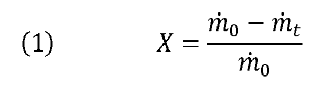
où X est le taux de conversion sans unité ;
ṁ0 est le débit massique de composition adhésive non réticulé au niveau du réservoir de stockage 82 sous forme de fût ;
ṁt est le débit massique de composition adhésive non réticulé au niveau de la buse 50. - Le débit de la composition adhésive 80 en ligne peut être ainsi être ajusté pour que, selon la cinétique de réaction et selon la température, en particulier dans le mélangeur statique, le taux de conversion de la réaction de réticulation de la composition adhésive reste inférieur ou égal à 30%, de préférence inférieur ou égal à 10%. Le débit de la composition adhésive 80 dans le dispositif de chauffage en ligne est par exemple compris entre 80 g.s-1 et 170 g.s-1, soit environ de 5 à 10 Kg par minutes, tel que égal à 120g.s-1, soit environ de 7 Kg par minutes.
- Pour permettre une mise en température d'application de la composition adhésive 80 à un débit élevé, le dispositif de chauffage en ligne 22 présente une structure adaptée à un chauffage très efficace. La
figure 6 montre une vue en coupe longitudinale d'un mode de réalisation du dispositif de chauffage en ligne 22. Pour permettre une mise en température rapide, le dispositif de chauffage en ligne 22 comporte un chauffage par induction. Ainsi, le dispositif de chauffage en ligne 22 comprend un câble inducteur 26, ici sous la forme d'un solénoïde, pour permettre la génération d'un champ magnétique. - Le dispositif de chauffage en ligne 22 comprend en outre un mélangeur statique 30 dans lequel la composition adhésive à chauffer 80 peut circuler. Les mélangeurs statiques sont notamment connus pour être utilisés dans l'industrie du moulage par injection afin d'homogénéiser la matière avant l'injection dans un moule. Les mélangeurs statiques connus de l'art antérieur comprennent des éléments de mélange présentant des surfaces de déflexion du fluide visant à obtenir un mélange homogène du fluide sur une courte distance et avec un faible cisaillement.
- De façon similaire aux mélangeurs statiques connus, le mélangeur statique 30 inclus dans le dispositif de chauffage en ligne 22 comprend au moins un tel élément de mélange 38. Tel qu'illustré, le mélangeur statique présente un ensemble d'éléments de mélange 38 disposés dans un fourreau 34. Le fourreau 34 forme un conduit de circulation de la composition adhésive 80. Le fourreau 34 et l'au moins un élément de mélange 38 constitue le mélangeur statique 30 du dispositif de chauffage en ligne 22. Lorsque le dispositif de chauffage en ligne 22 est intégré à l'installation 20 de la
figure 5 , le fourreau 34 en tant que conduit de circulation est une portion de la ligne 88. - L'échangeur statique 30 ici formé dans le dispositif de chauffage proposé 22 présente toutefois la particularité de comporter un matériau conducteur électriquement. Dans ce document, on entend par un matériau conducteur électriquement, un matériau présentant une résistivité inférieure à 10 Ω.m, de préférence inférieur 10-6 Ω.m. Le champ magnétique généré par le câble inducteur 26 entourant le mélangeur statique 30 est alors susceptible d'induire un courant électrique, connu sous le nom de courant de Foucault, dans le conducteur électrique du mélangeur statique 30. Les courants de Foucault induits dans le conducteur électrique entraînent un dégagement de chaleur par effet Joule qui se diffuse à la composition adhésive 80 par l'intermédiaire des composants du mélangeur statique 30.
- L'efficacité de l'échange thermique de la chaleur générée entre le mélangeur statique 30 et la composition adhésive 80 dépend de la structure du fourreau et, en particulier, des éléments de mélange 38 et de leur surface utile d'échange thermique. La
figure 7 montre un mode de réalisation d'un des éléments de mélange 38 du dispositif de chauffage en ligne 22. L'élément de mélange 38 présente des surfaces de déflexion 32 qui forment différents angles par rapport à la direction principale 28 de circulation de la composition adhésive 80 dans le mélangeur statique 30. Cet élément de mélange 38 présentant ces surfaces de déflexion possède alors une forte densité de surface en contact avec la composition adhésive 80 à mélanger. La densité de surface correspond à une quantité de surfaces d'échange par volume et est donc exprimé en m2/m3, i.e. en m-1. Les éléments de mélange 38 compris dans le dispositif de chauffage en ligne 22 peuvent présenter une densité de surface supérieure ou égale à 5 *103 m-1 de préférence comprise entre 5*103 m-1 et 10*103 m-1. De telles densités de surfaces correspondent par exemple à un mélangeur statique de 40 à 60 cm de long pour un diamètre de 4 à 6 cm et avec une surface utile de 5 à 10 m2. Dans l'application particulière ici envisagée du mélangeur statique 30 dans le dispositif de chauffage en ligne 22, une forte densité de surface permet l'obtention d'une grande surface utile d'échange thermique entre le mélangeur statique 30 et la composition adhésive 80 circulant. En d'autres termes, les surfaces de déflexion 32 forment un échangeur thermique de structure adaptée pour la mise en température d'application rapide de la composition adhésive 80 présent dans le fourreau 34. - Notamment dans le cas où le mélangeur statique 30 du dispositif de chauffage en ligne 22 ne présenterait pas une totalité de surface d'échange suffisante, l'installation 20 peut comprendre une recirculation de la composition adhésive dans le dispositif de chauffage en ligne 22. Cette recirculation, non illustrée, peut comprendre un piquage en aval du dispositif de chauffage en ligne 22 qui renvoie la composition adhésive à l'amont du dispositif de chauffage en ligne 22, par exemple à l'aide d'une pompe de circulation. Une telle recirculation permet d'augmenter le temps de séjour de la composition adhésive dans le dispositif de chauffage en ligne 22 sans réduire le débit de l'installation 80 et sans augmenter les dimensions du mélangeur statique. Par ailleurs, une telle recirculation facilite la montée en température de l'installation lors d'un redémarrage, en permettant la circulation de la composition adhésive dans le circuit formé de la recirculation et du dispositif de chauffage en ligne 22 tant que le dispositif de chauffage en ligne 22 n'a pas encore atteint la température souhaitée.
- En définitive, du fait de la circulation de la composition adhésive 80 et de la grande densité de surface d'échange, le dispositif de chauffage en ligne 22 permet la mise en température de la composition adhésive à la température d'application avec un faible temps de séjour. L'installation 20 d'application à chaud, avec la buse d'application 50, la ligne 88 d'alimentation de la buse et le dispositif de chauffage en ligne 22 peut ainsi appliquer sur la surface 96 des compositions adhésives 80 réticulables présentant une température d'application incluse dans la plage de réticulation de la composition adhésive 80 en limitant les risques de réticulation de la composition adhésive 80 en ligne 88.
- L'installation d'application 20 est aussi proposée avec le réservoir de stockage 82 comprenant la composition adhésive 80 à appliquer et relié à la ligne 88 d'alimentation de la buse 50. Il est en outre proposé un procédé d'application à chaud d'une composition adhésive comprenant la fourniture d'une telle installation d'application 20. Selon ce procédé, la composition adhésive circule depuis le réservoir de stockage jusqu'au dispositif de chauffage en ligne, par exemple à l'aide d'une pompe de circulation 46. La composition adhésive 80 est alors chauffée en ligne à l'aide du dispositif de chauffage 22 du fait de l'alimentation électrique du câble inducteur 26. Le câble inducteur 26 est par exemple alimenté à l'aide d'un courant électrique à haute fréquence, de préférence supérieure ou égale à 1 MHz, telle qu'à 15 MHz. Une fois mis à la température d'application, la composition adhésive 80 est appliquée sur la surface 96 par la buse d'application 50. Selon l'exemple précédemment cité, l'application peut être réalisée avec une viscosité du fluide de 15 Pa.s ± 5 Pa.s . La température d'application peut être comprise entre 50°C et 140°C. Plus particulièrement, la température d'application peut être comprise 80°C et 120°C ou encore comprise entre 100°C et 110°C.
- Le procédé d'application proposé est particulièrement avantageux lorsqu'il fait partie d'un procédé plus général de production d'un support adhésif réticulé. Un tel procédé de production d'un support adhésif réticulé est particulièrement proposé. Selon ce procédé, la surface 96 est fournie pour servir de support à l'application de la composition adhésive 80 selon le procédé d'application à chaud précédemment décrit. A la suite de l'application de la composition adhésive 80 sur la surface 96, le support enduit 98 est soumis à une température contrôlée, et avantageusement à un taux d'humidité contrôlé, pour permettre la réticulation de la composition adhésive. La température contrôlée peut être obtenue à l'aide d'un four ou d'une enceinte. La température de contrôle correspond à une température de réticulation de la composition adhésive 80 et est par exemple comprise entre 50°C et 200°C. Plus particulièrement, la température de réticulation est comprise entre 50°C et 180°C, de préférence entre 80°C et 160°C, plus préférentiellement comprise entre 100°C et 150°C ou encore comprise entre 100°C et 140°C. L'installation d'application précédemment décrite permettant l'application de la composition adhésive à chaud à une température d'application incluse dans la plage de réticulation de la composition adhésive, le procédé de production d'un support adhésif réticulé proposé est particulièrement avantageux lorsque les plages précédentes de températures d'application intersectent les plages de température de réticulation de la composition adhésive 80.
- Dans l'installation proposée et aussi pour les procédés d'application à chaud et de production proposés, la composition adhésive 80 à appliquer peut particulièrement être une composition adhésive comprenant au moins un prépolymère silylé, et au moins une résine tackifiante compatible. Cette composition adhésive comprend aussi de préférence au moins un catalyseur. Plus particulièrement la composition adhésive peut comprendre :
- De 20% à 85% en poids, de préférence de 30 à 75% en poids de l'au moins un prépolymère silylé ;
- De 15 à 80% en poids, de préférence de 25 à 70% en poids de l'au moins une résine tackifiante ;
- De 0,01 à 3 % en poids, de préférence de 0,1 à 2% en poids de l'au moins un catalyseur.
- La composition adhésive peut ainsi correspondre aux compositions adhésives décrites dans le document
WO 2012/090151 A2 , l'au moins un prépolymère silylé étant par exemple un polyuréthane ou un polyether comprenant 2 groupes terminaux de type alkoxysilane hydrolysables. - Lorsque la composition adhésive 80 est solide ou trop visqueuse sous conditions normales de températures et de pression, soit 1 bar et 20°C, il peut être aussi prévu des moyens de chauffage 44 dans le réservoir de stockage 82. Une trop grande viscosité, voire un état solide de la composition adhésive à la température ambiante peut en effet rendre difficile le pompage. Les moyens de chauffage 44 dans le réservoir de stockage 82, ici sous forme de fût, peuvent alors amener la composition adhésive à une température de pompage, c'est-à-dire à une température où la viscosité de la composition adhésive est suffisamment faible pour le pompage par la pompe de circulation 46. La pompe de circulation 46 peut typiquement être adaptée à faire circuler la composition adhésive 80 présentant une viscosité de 500 Pa.s, de préférence de 600 Pa.s. Selon un mode de réalisation particulièrement préféré, la pompe de circulation 46 peut pomper la composition adhésive 80 lorsqu'elle présente une viscosité de 1000 Pa.s. En d'autres termes, les moyens de chauffage 44 dans le réservoir de stockage permettent alors la montée en température à la température de pompage. Ces moyens de chauffage 44 sont aussi particulièrement utiles pour fondre la composition adhésive lorsque la composition adhésive est solide à température normale puis amener la composition adhésive à la température de pompage. La température de pompage de la composition adhésive 80 est par exemple une température de 40°C à 60°C. En d'autres termes, c'est le dispositif de chauffage en ligne 22 qui apporte la majeure partie de l'énergie de chauffage à la composition adhésive.
- Selon un mode de réalisation préféré de l'installation proposée 20, la buse d'application 50 peut aussi être chauffée. Le chauffage de la buse 50 contribue alors à la mise en température d'application de la composition adhésive 80. Ainsi selon ce mode de réalisation, la buse 50 d'application fait partie du dispositif de chauffage 22 à la température d'application. Le chauffage de la buse 50 permet d'apporter de l'énergie thermique en fin de ligne 88 pour amener la composition adhésive à la température finale d'application. Cette température finale d'application n'étant atteinte qu'en fin de ligne 88, le temps de séjour à cette température est court, limitant alors les risques de réticulation de la composition adhésive. Toutefois la puissance de chauffage de la buse d'application 90 est relativement faible, en étant typiquement de l'ordre de 200 W. Le chauffage de la composition adhésive par l'intermédiaire du mélangeur statique 30 chauffé par induction apporte alors la plus grande contribution au chauffage à la température finale d'application, par exemple de l'ordre de 10 KW à 20KW, même si la buse 90 chauffée peut finaliser la mise en température. Selon ce mode de réalisation, le mélangeur statique 30 peut chauffer la composition adhésive 80 à une température un peu plus faible, par exemple de 10°C ou moins, que la température finale d'application. La température de la composition adhésive 80 dans le mélangeur statique 30 étant plus faible que la température d'application, la durée de réticulation à cette température est plus faible et les risques de bouchon en ligne sont alors encore diminués.
- Selon un mode de réalisation préféré du dispositif de chauffage en ligne 22, le fourreau 34 est en matériau isolant. Dans ce document, on entend par matériau isolant électriquement un matériau présentant une résistivité supérieure ou égale à 106 Ω.m. Le matériau isolant du fourreau 34 est par exemple du verre ou un polymère dépourvu de charges conductrices. Selon ce mode de réalisation préféré, les éléments de mélange 38 sont réalisés en matériau conducteur électriquement pour permettre le chauffage par induction du mélangeur statique 30. En effet, comme indiqué précédemment, le câble inducteur 26 est susceptible, avec une alimentation électrique en courant alternatif, d'induire un courant de Foucault dans tout conducteur électrique placé dans le champ magnétique produit. Les courants de Foucault sont induits à la surface du premier conducteur placé dans le champ magnétique avec une profondeur de pénétration que l'on peut exprimer de la manière suivante :

où P est la profondeur de pénétration en m ; - p est la résistivité du matériau à chauffer en Ω.m ;
- f est la fréquence en Hz du courant alternatif alimentant le câble inducteur 26 ;
- µ0 est la perméabilité du vide égale à 4π* 10-7 en H.m-1;
- µr est la perméabilité relative (sans dimension) du matériau dans lequel sont induit les courants de Foucault.
- La réalisation du fourreau 34 en matériau isolant électriquement et des éléments de mélange en matériau conducteur permet alors de disposer les éléments de mélange comme premier conducteur dans le champ magnétique généré par le câble inducteur 26 entourant le fourreau 34. L'induction des courants de Foucault se réalise alors directement dans les éléments de mélange 38 au niveau des surfaces de déflexion 32, et non pas au niveau du fourreau 34 placé entre le câble inducteur et les éléments de mélange 38. La réalisation d'une induction et d'un effet Joule au niveau des surfaces de déflexion 32 permet un chauffage plus efficace de la composition adhésive 80 qui rentre en contact directement avec ces surfaces de déflexion 32, sans intermédiaire.
- Selon un mode de réalisation moins avantageux, le fourreau 34 est en matériau conducteur, de sorte que l'induction de courant de Foucault ne pénètrent que le fourreau 34 et pas les éléments de mélange 38. L'effet Joule se produit alors au niveau du fourreau 34, et la chaleur se diffuse à la composition adhésive 80 par conduction grâce à l'intermédiaire des surfaces de déflexion 32. Dans ce mode de réalisation moins avantageux proposé, l'échange thermique est moins efficace du fait de l'utilisation d'un intermédiaire pour conduire la chaleur.
- Le mode de réalisation préféré avec fourreau 34 isolant du dispositif de chauffage 22 est proposé pour le chauffage de tout fluide, en plus de l'utilisation pour le chauffage de la composition adhésive 80. Le dispositif de chauffage proposé 22 peut être utilisé pour le chauffage de tout fluide dans d'autre domaine que le domaine particulier de l'application de la composition adhésive 80 à chaud, tel que pour le chauffage d'une peinture par exemple. Un tel mode de réalisation du dispositif de chauffage proposé 22 permet alors un chauffage par induction amélioré en comparaison à une utilisation du chauffage par induction où seules les parois extérieures d'un moule ou d'un conduit de circulation sont chauffées par induction tel que dans les documents :
JP 2001 191 364 A JP 2001 191 380 A JP 2005/222781 A US 2011/0116340 A1 . En particulier dans le domaine technique du traitement thermique de la nourriture, le document précitéJP 2005/222781 A - Bien entendu, la présente invention n'est pas limitée aux exemples et aux modes de réalisation décrits et représentés, mais elle est susceptible de nombreuses variantes accessibles à l'homme de l'art.
Claims (12)
- Installation d'application à chaud d'une composition adhésive (80) sur un support (96), l'installation (20) comprenant :- une buse (50) d'application de la composition adhésive (80) ;- une ligne (88) d'alimentation de la buse (50) avec la composition adhésive (80) à appliquer sous forme fluide ;- un dispositif de chauffage (22) en ligne (88) de la composition adhésive (80) à une température d'application, le dispositif de chauffage (22) comprenant :* un mélangeur statique (30) comportant un matériau conducteur électriquement, et* un câble inducteur (26) entourant le mélangeur statique (30).
- Installation selon la revendication 1, comprenant un réservoir de stockage (82) comprenant la composition adhésive à appliquer (80), le réservoir de stockage (82) étant relié à la ligne d'alimentation (88) de la buse d'application (50).
- Installation selon la revendication 2, dans laquelle la composition adhésive à appliquer (80) comprend un prépolymère réactif, réticulant dans une plage de température, la composition adhésive à appliquer (80) présentant une plage de température d'application incluse dans la plage de température de réticulation.
- Installation selon la revendication 2 ou 3, dans laquelle la composition adhésive à appliquer (80) est fluide sous conditions normales de température et de pression.
- Installation selon l'une des revendications 1 à 4, comprenant des moyens de chauffage (44) apte à être disposés au niveau d'un réservoir de stockage (82) comprenant la composition adhésive à appliquer (80) pour élever la composition adhésive à appliquer (80) à une température de pompage.
- Installation selon l'une des revendications 1 à 5, comprenant une pompe (46) de circulation de la composition adhésive (80) dans la ligne d'alimentation (88), la pompe (46) étant apte à faire circuler une composition adhésive (80) présentant une viscosité de 1000 Pa.s, de préférence de 600 Pa.s, plus préférentiellement de 500 Pa.s.
- Installation selon l'une des revendications 1 à 6, dans laquelle le mélangeur statique (30) du dispositif de chauffage (22) comprend :- un fourreau (34) formant portion de la ligne d'alimentation (88) de composition adhésive, le fourreau étant réalisé en matériau isolant électriquement, de préférence en verre ou en polymère dépourvu de charges conductrices ; et- un élément de mélange (38) présentant des surfaces de déflexion (32) de la composition adhésive circulant dans le fourreau (34), l'élément de mélange (38) étant réalisé en matériau conducteur électriquement et disposé dans le fourreau (34).
- Installation selon la revendication 7, dans lequel l'élément de mélange (38) disposé dans le fourreau (34) présente une densité de surfaces d'échange thermique supérieure ou égale à 5*103 m-1, de préférence comprise entre 5*103 m-1 et 10*103 m-1.
- Procédé d'application à chaud d'une composition adhésive (80) sur un support (96), le procédé comprenant :- la fourniture d'une installation d'application (20) selon l'une des revendications 1 à 8 et d'un réservoir de stockage (82) comprenant la composition adhésive à appliquer (80) et relié à la ligne d'alimentation (88) de la buse d'application (50) ;- la circulation de la composition adhésive (80) depuis le réservoir de stockage (82) jusqu'au dispositif de chauffage (22) en ligne (88) ;- le chauffage de la composition adhésive pompée jusqu'à la température d'application, par l'alimentation électrique du câble inducteur (26) du dispositif de chauffage (22) ;- l'application à chaud de la composition adhésive (80) sur un support (96) à l'aide la buse d'application (50).
- Procédé d'application à chaud selon la revendication 9, dans lequel la composition adhésive (80) est appliquée avec une viscosité de 15 Pa.s ± 5 Pa.s.
- Procédé d'application à chaud selon la revendication 9 ou 10, dans lequel la composition adhésive (80) est appliquée à une température comprise entre 50°C et 140°, de préférence comprise entre 80°C et 120°C, plus préférentiellement entre 100°C et 110°C.
- Procédé de production d'un support adhésif réticulé, le procédé comprenant :- la fourniture d'un support (96) ;- l'application d'une composition adhésive (80) sur le support (96) à l'aide du procédé selon l'une des revendications 9 à 11 ;- la réticulation de la composition adhésive appliquée à une température comprise entre 50°C et 200°C, de préférence comprise entre 80°C et 160°C, plus préférentiellement entre 100°C et 140°C.
Applications Claiming Priority (1)
| Application Number | Priority Date | Filing Date | Title |
|---|---|---|---|
| FR1361818A FR3013993B1 (fr) | 2013-11-29 | 2013-11-29 | Installation et procede correspondant d'application a chaud d'une composition adhesive, dispositif de chauffage d'un fluide et utilisation correspondante |
Publications (2)
| Publication Number | Publication Date |
|---|---|
| EP2878364A1 true EP2878364A1 (fr) | 2015-06-03 |
| EP2878364B1 EP2878364B1 (fr) | 2016-10-19 |
Family
ID=50624665
Family Applications (1)
| Application Number | Title | Priority Date | Filing Date |
|---|---|---|---|
| EP14195521.1A Not-in-force EP2878364B1 (fr) | 2013-11-29 | 2014-11-28 | Installation et procédé correspondant d'application à chaud d'une composition adhésive |
Country Status (4)
| Country | Link |
|---|---|
| US (2) | US20150152292A1 (fr) |
| EP (1) | EP2878364B1 (fr) |
| ES (1) | ES2609031T3 (fr) |
| FR (1) | FR3013993B1 (fr) |
Cited By (2)
| Publication number | Priority date | Publication date | Assignee | Title |
|---|---|---|---|---|
| WO2019115952A1 (fr) * | 2017-12-14 | 2019-06-20 | Bostik Sa | Composition adhesive multicomposante et ses utilisations |
| CN112893030A (zh) * | 2021-01-13 | 2021-06-04 | 东莞市同协精密配件有限公司 | 一种智能制造工业自动化工艺板自动调节出胶宽度装置 |
Families Citing this family (4)
| Publication number | Priority date | Publication date | Assignee | Title |
|---|---|---|---|---|
| US9499355B2 (en) * | 2012-10-26 | 2016-11-22 | Nordson Corporation | Pedestal for supporting an adhesive melter and related systems and methods |
| CN108421475A (zh) * | 2018-05-25 | 2018-08-21 | 芜湖凌梦电子商务有限公司 | 一种石油管道生产加工喷漆用油漆搅拌装置 |
| AU2021200246A1 (en) | 2020-01-31 | 2021-08-19 | Howmedica Osteonics Corp. | Injection molding feedstock delivery system |
| FR3125054B1 (fr) | 2021-07-08 | 2024-11-08 | Bostik Sa | Nouvelle composition reticulable de polymere a terminaison silyl et article auto-adhesif correspondant |
Citations (6)
| Publication number | Priority date | Publication date | Assignee | Title |
|---|---|---|---|---|
| JP2001191380A (ja) | 2000-01-13 | 2001-07-17 | Asahi Kasei Corp | シリコーンゴム成形品の成形方法 |
| JP2001191364A (ja) | 2000-01-13 | 2001-07-17 | Asahi Kasei Corp | シリコーンゴム複合成形品の成形方法 |
| JP2005222781A (ja) | 2004-02-04 | 2005-08-18 | Shinko Sangyo Kk | 誘導加熱を用いた流動物加熱装置 |
| US20050230423A1 (en) * | 2004-04-14 | 2005-10-20 | Riney John M | Applicators for liquid hot melt adhesive and methods of applying liquid hot melt adhesive |
| US20110116340A1 (en) | 2008-08-07 | 2011-05-19 | Maschinenfabrik Gustav Eirich Gmbh & Co. Kg | Mixing Device Having Induction Heating |
| WO2012090151A2 (fr) | 2010-12-28 | 2012-07-05 | Bostik Sa | Procédé de réticulation et dispositif associé |
Family Cites Families (4)
| Publication number | Priority date | Publication date | Assignee | Title |
|---|---|---|---|---|
| US4106964A (en) * | 1976-06-11 | 1978-08-15 | Ransburg Corporation | Balance correction method and apparatus |
| JPS62117623A (ja) * | 1985-11-18 | 1987-05-29 | Inoue Seisakusho:Kk | インラインミキサ− |
| US20050095359A1 (en) * | 2003-10-31 | 2005-05-05 | Nordson Corporation | Hot melt adhesive system and method using machine readable information |
| US7707961B2 (en) * | 2005-08-12 | 2010-05-04 | Tmc-Ip, Llc | Apparatus for applying chemical coatings |
-
2013
- 2013-11-29 FR FR1361818A patent/FR3013993B1/fr active Active
-
2014
- 2014-11-25 US US14/552,646 patent/US20150152292A1/en not_active Abandoned
- 2014-11-28 EP EP14195521.1A patent/EP2878364B1/fr not_active Not-in-force
- 2014-11-28 ES ES14195521.1T patent/ES2609031T3/es active Active
-
2018
- 2018-07-30 US US16/049,440 patent/US20180334591A1/en not_active Abandoned
Patent Citations (6)
| Publication number | Priority date | Publication date | Assignee | Title |
|---|---|---|---|---|
| JP2001191380A (ja) | 2000-01-13 | 2001-07-17 | Asahi Kasei Corp | シリコーンゴム成形品の成形方法 |
| JP2001191364A (ja) | 2000-01-13 | 2001-07-17 | Asahi Kasei Corp | シリコーンゴム複合成形品の成形方法 |
| JP2005222781A (ja) | 2004-02-04 | 2005-08-18 | Shinko Sangyo Kk | 誘導加熱を用いた流動物加熱装置 |
| US20050230423A1 (en) * | 2004-04-14 | 2005-10-20 | Riney John M | Applicators for liquid hot melt adhesive and methods of applying liquid hot melt adhesive |
| US20110116340A1 (en) | 2008-08-07 | 2011-05-19 | Maschinenfabrik Gustav Eirich Gmbh & Co. Kg | Mixing Device Having Induction Heating |
| WO2012090151A2 (fr) | 2010-12-28 | 2012-07-05 | Bostik Sa | Procédé de réticulation et dispositif associé |
Cited By (5)
| Publication number | Priority date | Publication date | Assignee | Title |
|---|---|---|---|---|
| WO2019115952A1 (fr) * | 2017-12-14 | 2019-06-20 | Bostik Sa | Composition adhesive multicomposante et ses utilisations |
| FR3075218A1 (fr) * | 2017-12-14 | 2019-06-21 | Bostik Sa | Composition adhesive multicomposante et ses utilisations |
| US11708511B2 (en) | 2017-12-14 | 2023-07-25 | Bostik Sa | Adhesive multicomponent composition and uses thereof |
| CN112893030A (zh) * | 2021-01-13 | 2021-06-04 | 东莞市同协精密配件有限公司 | 一种智能制造工业自动化工艺板自动调节出胶宽度装置 |
| CN112893030B (zh) * | 2021-01-13 | 2022-06-17 | 汇智才鑫(盐城)智能科技有限公司 | 一种智能制造工业自动化工艺板自动调节出胶宽度装置 |
Also Published As
| Publication number | Publication date |
|---|---|
| ES2609031T3 (es) | 2017-04-18 |
| EP2878364B1 (fr) | 2016-10-19 |
| US20180334591A1 (en) | 2018-11-22 |
| FR3013993A1 (fr) | 2015-06-05 |
| US20150152292A1 (en) | 2015-06-04 |
| FR3013993B1 (fr) | 2016-03-04 |
Similar Documents
| Publication | Publication Date | Title |
|---|---|---|
| EP2878364B1 (fr) | Installation et procédé correspondant d'application à chaud d'une composition adhésive | |
| EP0617727A1 (fr) | Procede de collage de deux substrats non metalliques a l'aide d'un adhesif | |
| FR2482517A1 (fr) | Procede et appareil de moulage par extrusion de caoutchoucs et de resines synthetiques aptes a creer des liaisons transversales thermiques | |
| EP2886201B1 (fr) | Procédé d'application à chaud d'une composition adhésive silylée | |
| FR2458323A1 (fr) | Procede et appareil pour le traitement par micro-ondes de revetements sur substrats | |
| EP0329529B1 (fr) | Procédé de jonction de pièces en matière plastique, en utilisant un agent de réticulation et une résistance électrique de chauffage | |
| EP3194143B1 (fr) | Procédé de mise en forme à chaud d'un matériau thermoplastique et installation de mise en oeuvre | |
| CN207823515U (zh) | 激光清洗机及激光清洗设备 | |
| EP3022037B1 (fr) | Procédé d'assemblage de pièces de turbomachine | |
| FR2775621A1 (fr) | Dispositif melangeur et de traitement thermique de produits solides ou liquides | |
| EP2935382A2 (fr) | Composition comprenant une résine phénolique, matériau composite comprenant une telle composition et procédé de préparation d'un matériau composite | |
| CN108854663A (zh) | 一种印刷uv油墨的恒温搅拌装置 | |
| EP0637723B1 (fr) | Dispositif échangeur pour le chauffage d'un fluide visqueux | |
| FR3130679A1 (fr) | Dispositif et procédé de fabrication d’une pièce en matériau composite pour un ensemble propulsif d’aéronef | |
| WO2017134397A1 (fr) | Pile a combustible et système de chauffage associé | |
| EP2896055A1 (fr) | Procede de fabrication d'un cable de transport d'energie electrique et cable fabrique par un tel procede | |
| FR3151521A1 (fr) | Dispositif de chauffage d’une resine pour une installation de fabrication d’une piece composite | |
| FR3165571A1 (fr) | Procédé de fabrication d’un panneau multicellulaire par soudage conductif ou par soudage radiatif | |
| JP4300318B1 (ja) | 定着用回転体およびその製造方法 | |
| WO2023026008A1 (fr) | Procede de fabrication d'une piece composite, en particulier aeronautique et installation associee | |
| EP1851772B1 (fr) | Colmatage de fissures sur des dispositifs metalliques destines a contenir des matieres acides et radioactives | |
| Teytu | Organic cooled high flux, heating element working under radiations; Canaux chauffants a haut flux thermique pour boucles a liquides organiques sous irradiations | |
| JP2005248064A (ja) | カーボンブラック分散ポリアミド酸溶液の製造方法および半導電性ポリイミドベルト | |
| Teytu | Organic cooled high flux, heating element working under radiations | |
| JP2001126857A (ja) | 液状流体の加熱装置 |
Legal Events
| Date | Code | Title | Description |
|---|---|---|---|
| PUAI | Public reference made under article 153(3) epc to a published international application that has entered the european phase |
Free format text: ORIGINAL CODE: 0009012 |
|
| 17P | Request for examination filed |
Effective date: 20141128 |
|
| AK | Designated contracting states |
Kind code of ref document: A1 Designated state(s): AL AT BE BG CH CY CZ DE DK EE ES FI FR GB GR HR HU IE IS IT LI LT LU LV MC MK MT NL NO PL PT RO RS SE SI SK SM TR |
|
| AX | Request for extension of the european patent |
Extension state: BA ME |
|
| R17P | Request for examination filed (corrected) |
Effective date: 20151203 |
|
| RBV | Designated contracting states (corrected) |
Designated state(s): AL AT BE BG CH CY CZ DE DK EE ES FI FR GB GR HR HU IE IS IT LI LT LU LV MC MK MT NL NO PL PT RO RS SE SI SK SM TR |
|
| GRAP | Despatch of communication of intention to grant a patent |
Free format text: ORIGINAL CODE: EPIDOSNIGR1 |
|
| INTG | Intention to grant announced |
Effective date: 20160511 |
|
| GRAS | Grant fee paid |
Free format text: ORIGINAL CODE: EPIDOSNIGR3 |
|
| GRAA | (expected) grant |
Free format text: ORIGINAL CODE: 0009210 |
|
| AK | Designated contracting states |
Kind code of ref document: B1 Designated state(s): AL AT BE BG CH CY CZ DE DK EE ES FI FR GB GR HR HU IE IS IT LI LT LU LV MC MK MT NL NO PL PT RO RS SE SI SK SM TR |
|
| REG | Reference to a national code |
Ref country code: GB Ref legal event code: FG4D Free format text: NOT ENGLISH |
|
| REG | Reference to a national code |
Ref country code: CH Ref legal event code: EP |
|
| REG | Reference to a national code |
Ref country code: AT Ref legal event code: REF Ref document number: 837855 Country of ref document: AT Kind code of ref document: T Effective date: 20161115 |
|
| REG | Reference to a national code |
Ref country code: IE Ref legal event code: FG4D Free format text: LANGUAGE OF EP DOCUMENT: FRENCH |
|
| REG | Reference to a national code |
Ref country code: DE Ref legal event code: R096 Ref document number: 602014004344 Country of ref document: DE |
|
| REG | Reference to a national code |
Ref country code: NL Ref legal event code: FP |
|
| REG | Reference to a national code |
Ref country code: FR Ref legal event code: PLFP Year of fee payment: 3 |
|
| REG | Reference to a national code |
Ref country code: LT Ref legal event code: MG4D |
|
| PG25 | Lapsed in a contracting state [announced via postgrant information from national office to epo] |
Ref country code: LV Free format text: LAPSE BECAUSE OF FAILURE TO SUBMIT A TRANSLATION OF THE DESCRIPTION OR TO PAY THE FEE WITHIN THE PRESCRIBED TIME-LIMIT Effective date: 20161019 Ref country code: BE Free format text: LAPSE BECAUSE OF NON-PAYMENT OF DUE FEES Effective date: 20161130 |
|
| REG | Reference to a national code |
Ref country code: AT Ref legal event code: MK05 Ref document number: 837855 Country of ref document: AT Kind code of ref document: T Effective date: 20161019 |
|
| REG | Reference to a national code |
Ref country code: ES Ref legal event code: FG2A Ref document number: 2609031 Country of ref document: ES Kind code of ref document: T3 Effective date: 20170418 |
|
| PG25 | Lapsed in a contracting state [announced via postgrant information from national office to epo] |
Ref country code: SE Free format text: LAPSE BECAUSE OF FAILURE TO SUBMIT A TRANSLATION OF THE DESCRIPTION OR TO PAY THE FEE WITHIN THE PRESCRIBED TIME-LIMIT Effective date: 20161019 Ref country code: NO Free format text: LAPSE BECAUSE OF FAILURE TO SUBMIT A TRANSLATION OF THE DESCRIPTION OR TO PAY THE FEE WITHIN THE PRESCRIBED TIME-LIMIT Effective date: 20170119 Ref country code: GR Free format text: LAPSE BECAUSE OF FAILURE TO SUBMIT A TRANSLATION OF THE DESCRIPTION OR TO PAY THE FEE WITHIN THE PRESCRIBED TIME-LIMIT Effective date: 20170120 Ref country code: LT Free format text: LAPSE BECAUSE OF FAILURE TO SUBMIT A TRANSLATION OF THE DESCRIPTION OR TO PAY THE FEE WITHIN THE PRESCRIBED TIME-LIMIT Effective date: 20161019 |
|
| PG25 | Lapsed in a contracting state [announced via postgrant information from national office to epo] |
Ref country code: PT Free format text: LAPSE BECAUSE OF FAILURE TO SUBMIT A TRANSLATION OF THE DESCRIPTION OR TO PAY THE FEE WITHIN THE PRESCRIBED TIME-LIMIT Effective date: 20170220 Ref country code: PL Free format text: LAPSE BECAUSE OF FAILURE TO SUBMIT A TRANSLATION OF THE DESCRIPTION OR TO PAY THE FEE WITHIN THE PRESCRIBED TIME-LIMIT Effective date: 20161019 Ref country code: FI Free format text: LAPSE BECAUSE OF FAILURE TO SUBMIT A TRANSLATION OF THE DESCRIPTION OR TO PAY THE FEE WITHIN THE PRESCRIBED TIME-LIMIT Effective date: 20161019 Ref country code: HR Free format text: LAPSE BECAUSE OF FAILURE TO SUBMIT A TRANSLATION OF THE DESCRIPTION OR TO PAY THE FEE WITHIN THE PRESCRIBED TIME-LIMIT Effective date: 20161019 Ref country code: IS Free format text: LAPSE BECAUSE OF FAILURE TO SUBMIT A TRANSLATION OF THE DESCRIPTION OR TO PAY THE FEE WITHIN THE PRESCRIBED TIME-LIMIT Effective date: 20170219 Ref country code: RS Free format text: LAPSE BECAUSE OF FAILURE TO SUBMIT A TRANSLATION OF THE DESCRIPTION OR TO PAY THE FEE WITHIN THE PRESCRIBED TIME-LIMIT Effective date: 20161019 Ref country code: AT Free format text: LAPSE BECAUSE OF FAILURE TO SUBMIT A TRANSLATION OF THE DESCRIPTION OR TO PAY THE FEE WITHIN THE PRESCRIBED TIME-LIMIT Effective date: 20161019 |
|
| REG | Reference to a national code |
Ref country code: DE Ref legal event code: R097 Ref document number: 602014004344 Country of ref document: DE |
|
| PG25 | Lapsed in a contracting state [announced via postgrant information from national office to epo] |
Ref country code: RO Free format text: LAPSE BECAUSE OF FAILURE TO SUBMIT A TRANSLATION OF THE DESCRIPTION OR TO PAY THE FEE WITHIN THE PRESCRIBED TIME-LIMIT Effective date: 20161019 Ref country code: MC Free format text: LAPSE BECAUSE OF FAILURE TO SUBMIT A TRANSLATION OF THE DESCRIPTION OR TO PAY THE FEE WITHIN THE PRESCRIBED TIME-LIMIT Effective date: 20161019 Ref country code: DK Free format text: LAPSE BECAUSE OF FAILURE TO SUBMIT A TRANSLATION OF THE DESCRIPTION OR TO PAY THE FEE WITHIN THE PRESCRIBED TIME-LIMIT Effective date: 20161019 Ref country code: SK Free format text: LAPSE BECAUSE OF FAILURE TO SUBMIT A TRANSLATION OF THE DESCRIPTION OR TO PAY THE FEE WITHIN THE PRESCRIBED TIME-LIMIT Effective date: 20161019 Ref country code: EE Free format text: LAPSE BECAUSE OF FAILURE TO SUBMIT A TRANSLATION OF THE DESCRIPTION OR TO PAY THE FEE WITHIN THE PRESCRIBED TIME-LIMIT Effective date: 20161019 Ref country code: CZ Free format text: LAPSE BECAUSE OF FAILURE TO SUBMIT A TRANSLATION OF THE DESCRIPTION OR TO PAY THE FEE WITHIN THE PRESCRIBED TIME-LIMIT Effective date: 20161019 |
|
| REG | Reference to a national code |
Ref country code: IE Ref legal event code: MM4A |
|
| PLBE | No opposition filed within time limit |
Free format text: ORIGINAL CODE: 0009261 |
|
| STAA | Information on the status of an ep patent application or granted ep patent |
Free format text: STATUS: NO OPPOSITION FILED WITHIN TIME LIMIT |
|
| PG25 | Lapsed in a contracting state [announced via postgrant information from national office to epo] |
Ref country code: BG Free format text: LAPSE BECAUSE OF FAILURE TO SUBMIT A TRANSLATION OF THE DESCRIPTION OR TO PAY THE FEE WITHIN THE PRESCRIBED TIME-LIMIT Effective date: 20170119 Ref country code: SM Free format text: LAPSE BECAUSE OF FAILURE TO SUBMIT A TRANSLATION OF THE DESCRIPTION OR TO PAY THE FEE WITHIN THE PRESCRIBED TIME-LIMIT Effective date: 20161019 |
|
| 26N | No opposition filed |
Effective date: 20170720 |
|
| PG25 | Lapsed in a contracting state [announced via postgrant information from national office to epo] |
Ref country code: LU Free format text: LAPSE BECAUSE OF NON-PAYMENT OF DUE FEES Effective date: 20161130 |
|
| REG | Reference to a national code |
Ref country code: FR Ref legal event code: PLFP Year of fee payment: 4 |
|
| PG25 | Lapsed in a contracting state [announced via postgrant information from national office to epo] |
Ref country code: SI Free format text: LAPSE BECAUSE OF FAILURE TO SUBMIT A TRANSLATION OF THE DESCRIPTION OR TO PAY THE FEE WITHIN THE PRESCRIBED TIME-LIMIT Effective date: 20161019 Ref country code: IE Free format text: LAPSE BECAUSE OF NON-PAYMENT OF DUE FEES Effective date: 20161128 |
|
| PGFP | Annual fee paid to national office [announced via postgrant information from national office to epo] |
Ref country code: DE Payment date: 20171121 Year of fee payment: 4 Ref country code: NL Payment date: 20171115 Year of fee payment: 4 |
|
| REG | Reference to a national code |
Ref country code: BE Ref legal event code: MM Effective date: 20161130 |
|
| PGFP | Annual fee paid to national office [announced via postgrant information from national office to epo] |
Ref country code: ES Payment date: 20171201 Year of fee payment: 4 Ref country code: IT Payment date: 20171130 Year of fee payment: 4 |
|
| PG25 | Lapsed in a contracting state [announced via postgrant information from national office to epo] |
Ref country code: HU Free format text: LAPSE BECAUSE OF FAILURE TO SUBMIT A TRANSLATION OF THE DESCRIPTION OR TO PAY THE FEE WITHIN THE PRESCRIBED TIME-LIMIT; INVALID AB INITIO Effective date: 20141128 |
|
| PG25 | Lapsed in a contracting state [announced via postgrant information from national office to epo] |
Ref country code: CY Free format text: LAPSE BECAUSE OF FAILURE TO SUBMIT A TRANSLATION OF THE DESCRIPTION OR TO PAY THE FEE WITHIN THE PRESCRIBED TIME-LIMIT Effective date: 20161019 Ref country code: MK Free format text: LAPSE BECAUSE OF FAILURE TO SUBMIT A TRANSLATION OF THE DESCRIPTION OR TO PAY THE FEE WITHIN THE PRESCRIBED TIME-LIMIT Effective date: 20161019 |
|
| PG25 | Lapsed in a contracting state [announced via postgrant information from national office to epo] |
Ref country code: LI Free format text: LAPSE BECAUSE OF NON-PAYMENT OF DUE FEES Effective date: 20171130 Ref country code: CH Free format text: LAPSE BECAUSE OF NON-PAYMENT OF DUE FEES Effective date: 20171130 |
|
| PG25 | Lapsed in a contracting state [announced via postgrant information from national office to epo] |
Ref country code: MT Free format text: LAPSE BECAUSE OF FAILURE TO SUBMIT A TRANSLATION OF THE DESCRIPTION OR TO PAY THE FEE WITHIN THE PRESCRIBED TIME-LIMIT Effective date: 20161019 |
|
| REG | Reference to a national code |
Ref country code: FR Ref legal event code: PLFP Year of fee payment: 5 |
|
| PG25 | Lapsed in a contracting state [announced via postgrant information from national office to epo] |
Ref country code: TR Free format text: LAPSE BECAUSE OF FAILURE TO SUBMIT A TRANSLATION OF THE DESCRIPTION OR TO PAY THE FEE WITHIN THE PRESCRIBED TIME-LIMIT Effective date: 20161019 |
|
| PGFP | Annual fee paid to national office [announced via postgrant information from national office to epo] |
Ref country code: FR Payment date: 20181011 Year of fee payment: 5 |
|
| REG | Reference to a national code |
Ref country code: DE Ref legal event code: R119 Ref document number: 602014004344 Country of ref document: DE |
|
| REG | Reference to a national code |
Ref country code: NL Ref legal event code: MM Effective date: 20181201 |
|
| GBPC | Gb: european patent ceased through non-payment of renewal fee |
Effective date: 20181128 |
|
| PG25 | Lapsed in a contracting state [announced via postgrant information from national office to epo] |
Ref country code: NL Free format text: LAPSE BECAUSE OF NON-PAYMENT OF DUE FEES Effective date: 20181201 |
|
| PG25 | Lapsed in a contracting state [announced via postgrant information from national office to epo] |
Ref country code: DE Free format text: LAPSE BECAUSE OF NON-PAYMENT OF DUE FEES Effective date: 20190601 Ref country code: IT Free format text: LAPSE BECAUSE OF NON-PAYMENT OF DUE FEES Effective date: 20181128 |
|
| PG25 | Lapsed in a contracting state [announced via postgrant information from national office to epo] |
Ref country code: GB Free format text: LAPSE BECAUSE OF NON-PAYMENT OF DUE FEES Effective date: 20181128 |
|
| REG | Reference to a national code |
Ref country code: ES Ref legal event code: FD2A Effective date: 20200102 |
|
| PG25 | Lapsed in a contracting state [announced via postgrant information from national office to epo] |
Ref country code: ES Free format text: LAPSE BECAUSE OF NON-PAYMENT OF DUE FEES Effective date: 20181129 |
|
| PG25 | Lapsed in a contracting state [announced via postgrant information from national office to epo] |
Ref country code: AL Free format text: LAPSE BECAUSE OF FAILURE TO SUBMIT A TRANSLATION OF THE DESCRIPTION OR TO PAY THE FEE WITHIN THE PRESCRIBED TIME-LIMIT Effective date: 20161019 |
|
| PG25 | Lapsed in a contracting state [announced via postgrant information from national office to epo] |
Ref country code: FR Free format text: LAPSE BECAUSE OF NON-PAYMENT OF DUE FEES Effective date: 20191130 |