EP2878488A1 - Luftausströmer - Google Patents
Luftausströmer Download PDFInfo
- Publication number
- EP2878488A1 EP2878488A1 EP14193455.4A EP14193455A EP2878488A1 EP 2878488 A1 EP2878488 A1 EP 2878488A1 EP 14193455 A EP14193455 A EP 14193455A EP 2878488 A1 EP2878488 A1 EP 2878488A1
- Authority
- EP
- European Patent Office
- Prior art keywords
- air vent
- air
- light guide
- optical fiber
- insert
- Prior art date
- Legal status (The legal status is an assumption and is not a legal conclusion. Google has not performed a legal analysis and makes no representation as to the accuracy of the status listed.)
- Granted
Links
Images


Classifications
-
- B—PERFORMING OPERATIONS; TRANSPORTING
- B60—VEHICLES IN GENERAL
- B60H—ARRANGEMENTS OF HEATING, COOLING, VENTILATING OR OTHER AIR-TREATING DEVICES SPECIALLY ADAPTED FOR PASSENGER OR GOODS SPACES OF VEHICLES
- B60H1/00—Heating, cooling or ventilating devices
- B60H1/00007—Combined heating, ventilating, or cooling devices
- B60H1/00207—Combined heating, ventilating, or cooling devices characterised by the position of the HVAC devices with respect to the passenger compartment
-
- B—PERFORMING OPERATIONS; TRANSPORTING
- B60—VEHICLES IN GENERAL
- B60H—ARRANGEMENTS OF HEATING, COOLING, VENTILATING OR OTHER AIR-TREATING DEVICES SPECIALLY ADAPTED FOR PASSENGER OR GOODS SPACES OF VEHICLES
- B60H1/00—Heating, cooling or ventilating devices
- B60H1/34—Nozzles; Air-diffusers
-
- B—PERFORMING OPERATIONS; TRANSPORTING
- B60—VEHICLES IN GENERAL
- B60H—ARRANGEMENTS OF HEATING, COOLING, VENTILATING OR OTHER AIR-TREATING DEVICES SPECIALLY ADAPTED FOR PASSENGER OR GOODS SPACES OF VEHICLES
- B60H1/00—Heating, cooling or ventilating devices
- B60H1/34—Nozzles; Air-diffusers
- B60H1/3414—Nozzles; Air-diffusers with means for adjusting the air stream direction
-
- B—PERFORMING OPERATIONS; TRANSPORTING
- B60—VEHICLES IN GENERAL
- B60Q—ARRANGEMENT OF SIGNALLING OR LIGHTING DEVICES, THE MOUNTING OR SUPPORTING THEREOF OR CIRCUITS THEREFOR, FOR VEHICLES IN GENERAL
- B60Q3/00—Arrangement of lighting devices for vehicle interiors; Lighting devices specially adapted for vehicle interiors
- B60Q3/20—Arrangement of lighting devices for vehicle interiors; Lighting devices specially adapted for vehicle interiors for lighting specific fittings of passenger or driving compartments; mounted on specific fittings of passenger or driving compartments
-
- B—PERFORMING OPERATIONS; TRANSPORTING
- B60—VEHICLES IN GENERAL
- B60Q—ARRANGEMENT OF SIGNALLING OR LIGHTING DEVICES, THE MOUNTING OR SUPPORTING THEREOF OR CIRCUITS THEREFOR, FOR VEHICLES IN GENERAL
- B60Q3/00—Arrangement of lighting devices for vehicle interiors; Lighting devices specially adapted for vehicle interiors
- B60Q3/60—Arrangement of lighting devices for vehicle interiors; Lighting devices specially adapted for vehicle interiors characterised by optical aspects
- B60Q3/62—Arrangement of lighting devices for vehicle interiors; Lighting devices specially adapted for vehicle interiors characterised by optical aspects using light guides
- B60Q3/64—Arrangement of lighting devices for vehicle interiors; Lighting devices specially adapted for vehicle interiors characterised by optical aspects using light guides for a single lighting device
-
- F—MECHANICAL ENGINEERING; LIGHTING; HEATING; WEAPONS; BLASTING
- F24—HEATING; RANGES; VENTILATING
- F24F—AIR-CONDITIONING; AIR-HUMIDIFICATION; VENTILATION; USE OF AIR CURRENTS FOR SCREENING
- F24F13/00—Details common to, or for air-conditioning, air-humidification, ventilation or use of air currents for screening
- F24F13/02—Ducting arrangements
- F24F13/06—Outlets for directing or distributing air into rooms or spaces, e.g. ceiling air diffuser
-
- B—PERFORMING OPERATIONS; TRANSPORTING
- B60—VEHICLES IN GENERAL
- B60H—ARRANGEMENTS OF HEATING, COOLING, VENTILATING OR OTHER AIR-TREATING DEVICES SPECIALLY ADAPTED FOR PASSENGER OR GOODS SPACES OF VEHICLES
- B60H1/00—Heating, cooling or ventilating devices
- B60H1/00007—Combined heating, ventilating, or cooling devices
- B60H1/00207—Combined heating, ventilating, or cooling devices characterised by the position of the HVAC devices with respect to the passenger compartment
- B60H2001/00228—Devices in the interior of the passenger compartment
-
- B—PERFORMING OPERATIONS; TRANSPORTING
- B60—VEHICLES IN GENERAL
- B60H—ARRANGEMENTS OF HEATING, COOLING, VENTILATING OR OTHER AIR-TREATING DEVICES SPECIALLY ADAPTED FOR PASSENGER OR GOODS SPACES OF VEHICLES
- B60H1/00—Heating, cooling or ventilating devices
- B60H1/34—Nozzles; Air-diffusers
- B60H2001/3471—Details of actuators
- B60H2001/3478—Details of actuators acting on additional damper doors
-
- B—PERFORMING OPERATIONS; TRANSPORTING
- B60—VEHICLES IN GENERAL
- B60Q—ARRANGEMENT OF SIGNALLING OR LIGHTING DEVICES, THE MOUNTING OR SUPPORTING THEREOF OR CIRCUITS THEREFOR, FOR VEHICLES IN GENERAL
- B60Q2500/00—Special features or arrangements of vehicle interior lamps
- B60Q2500/20—Special features or arrangements of vehicle interior lamps associated with air conditioning arrangements
-
- F—MECHANICAL ENGINEERING; LIGHTING; HEATING; WEAPONS; BLASTING
- F24—HEATING; RANGES; VENTILATING
- F24F—AIR-CONDITIONING; AIR-HUMIDIFICATION; VENTILATION; USE OF AIR CURRENTS FOR SCREENING
- F24F13/00—Details common to, or for air-conditioning, air-humidification, ventilation or use of air currents for screening
- F24F13/08—Air-flow control members, e.g. louvres, grilles, flaps or guide plates
- F24F13/10—Air-flow control members, e.g. louvres, grilles, flaps or guide plates movable, e.g. dampers
- F24F13/14—Air-flow control members, e.g. louvres, grilles, flaps or guide plates movable, e.g. dampers built up of tilting members, e.g. louvre
- F24F13/1426—Air-flow control members, e.g. louvres, grilles, flaps or guide plates movable, e.g. dampers built up of tilting members, e.g. louvre characterised by actuating means
- F24F2013/1446—Air-flow control members, e.g. louvres, grilles, flaps or guide plates movable, e.g. dampers built up of tilting members, e.g. louvre characterised by actuating means with gearings
Definitions
- the present invention relates to an air vent.
- Air vents for motor vehicles are already known from the prior art.
- the air vents are used, for example, to ventilate the interior of the motor vehicle and to air-condition,
- the direction and volume of the airflow flowing into the vehicle interior can be adjusted.
- slats or inserts as well as flaps are provided on the air vent.
- Air vents for motor vehicles are already known from the prior art, which are backlit.
- the ventilation device comprises a discharge nozzle and lighting means.
- the bulbs can detect whether the air flow from the exhaust nozzle can flow into the vehicle interior.
- the DE 201 18 014 U1 discloses an air nozzle for the outlet of an airflow from an air supply duct.
- the air nozzle has an operating element which allows an adjustment of the slats of the air nozzle.
- This control element has a backlit light exit section, which detects the orientation of the control element and thus the air flow in the dark.
- an air vent with the features of claim 1. Thereafter, an air vent on a setting insert for adjusting the effluent through the air vent airflow, wherein the air flow is adjustable by a rotation of the setting insert, with at least a first light guide and at least a second optical fiber, wherein the first optical fiber fixedly attached to a housing of the Heilausströmers and the second optical fiber fixed to the setting insert.
- the first light guide and the second light guide are rotatable relative to each other and the second light guide can be illuminated by the first light guide. Through the second light guide, a backlit portion of the adjustment is further illuminated.
- the backlight of Heilausströmers requires no complex construction, but it can be realized in a simple design.
- Light can be introduced into the first optical waveguide via one or more LEDs and forwarded from there into the second optical waveguide.
- the rotation of the backlit portion takes place in particular synchronously with the rotation of the setting insert, with which the effluent through the air vent air flow is adjusted.
- the illumination of the second light guide is homogeneous over the entire adjustment. Consequently, the backlightable portion is illuminated with substantially the same intensity substantially over the entire adjustment range. Based on the position of the backlit portion can easily and reliably read the rotation of the setting insert and thus the setting or intensity of the air stream flowing through the air vent and possibly adjusted accordingly.
- the LED or light-emitting diode used can be, for example, an RGB color light-emitting diode (RGB LED).
- RGB LED RGB color light-emitting diode
- the color of the lighting can be adjusted or freely selected by the driver. It is also possible that the color of the lighting to driving modes of the manufacturer preset or is customizable. Thus, for example, the ECO mode, a green lighting and the Sport mode, a red lighting, etc. be assigned.
- the first light guide is at least partially, preferably completely, designed as a luminous film. This has the advantage that, for example, can be dispensed with the use of LEDs.
- the adjustment insert comprises an adjusting ring, wherein the adjusting ring and the second light guide are connected to each other.
- the adjusting ring allows easy adjustment of the adjustment insert and thus a simple adjustment of the outflowing through the air vent airflow.
- the combination of adjusting ring and second light guide is a particularly simple and reliable way to couple the rotation of the adjustment insert with the rotation of the backlit portion.
- the adjustment insert may comprise a trim ring in which the backlit portion is disposed.
- the ornamental ring is used to veneer the gap between the adjustment insert and the housing of the air vent.
- the backlit portion is an on-off symbol. This symbol is distributed around the world and, because of its distribution, is understood almost everywhere in the world. Compared to previously known systems, the operability of the air vent is significantly improved. In addition, the operator can see at a glance whether the air vent is closed or open. Based on the position of the backlit section, the operator also recognizes the current setting of the air vent.
- the air vent may be illuminated as soon as the vehicle is unlocked or started or when the vehicle's lighting is switched on.
- the second optical fiber has a light receiving section, by means of which the light from the first optical fiber to the second optical fiber is channeled transferable.
- the second optical fiber has a light receiving section, by means of which the light from the first optical fiber to the second optical fiber is channeled transferable.
- first and the second optical fiber do not touch each other. This prevents jamming of the first and second optical fibers and ensures that the first and second optical fibers can be twisted against each other without problems. Between the first and the second light guide, a gap of less than one millimeter may be provided.
- the adjustment insert may include a first rotation stop and a second rotation stop that define an adjustment range for the adjustment insert.
- the adjustment insert can only be rotated between the first rotation stop and the second rotation stop.
- An adjustment of the outflow of air through the air flow occurs between the first and second rotation stop. In the position of the first rotation stopper no air flows through the air vent and in the position of the second rotation stop air flows with maximum mass air flow through the air vent.
- a switching device can be provided which switches off or on the lighting of the air vent, and that the reaching or leaving of the first rotary stop actuates the switching device.
- the air vent in the position of the first rotation stop the air vent is closed, so that no air flows through the air vent, and that in the position of the second rotation stop the air vent is open to the maximum.
- the adjusting device may comprise at least one transmission element for actuating a flap mechanism of the Luftausströmers, wherein by means of the transmission element at the same time the switching device is actuated.
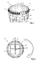
- FIG. 1 shows a perspective view of an embodiment of a Heilausströmers invention 10 for a motor vehicle. In this case, only the components are shown, which are necessary or helpful for the understanding of the invention.
- the air vent 10 has a housing 12, e.g. is used in the dashboard of a motor vehicle.
- an abutment ring 13 is attached on the housing 12.
- the contact ring 13 serves for fastening the Luftauströmers 10, for example, in the dashboard not shown in detail.
- the air vent 10 further comprises a setting insert 14.
- the adjusting insert 14 includes an adjusting ring 16 and a decorative ring 18 as external components.
- the trim ring 18 is clipped into the adjusting ring 16 and so firmly connected to the adjusting ring 16.
- the adjusting ring 16 has a nose 19 with a backlit portion 20.
- the air vent 10 and its components, so the housing 12, the adjustment insert 14, the adjusting ring 16, trim ring 18 and the backlit portion 20 are made of plastic.
- the backlit portion 20 is disposed in the nose 19 of the trim ring 18, which is integrally formed on the trim ring 18.
- the shape of the nose 19 is approximated to a trapeze and rounded at the corners.
- the adjusting ring 16 has an annular groove 17, in which the trim ring 18 is clipped.
- the adjusting ring 16 has an inverted trapezoidal recess 22, which surrounds the nose 19 at its edges, but they do not obscure.
- the backlightable section 20 is an on-off icon 21 (see FIG. FIG. 7 and FIG. 8 ).
- FIG. 2 shows a plan view of the air vent 10 according to FIG. 1 , The disk sets of Luftausströmers 10 are not shown here.
- the adjustment insert 14 has a first rotation stop D1 and a second rotation stop D2, which define an actuating region for the adjustment insert 14. Between the rotation stop D1 and the rotation stop D2 is an operating range of about 80 °, which is defined by the rotation stop D1 and the rotation stop D2.
- first rotational stop is arranged at about "15:00 o'clock” and the second rotational stopper at approximately "9 o'clock”. This results in an operating range of approximately 180 °.
- FIG. 3 shows a perspective view of the trim ring 18 of the air vent 10th
- the trim ring 18 has an upper side, which is visible after insertion into the adjusting ring 16 and protrudes from the adjusting ring 16.
- the trim ring 18 and the adjusting ring 16 are formed such that after insertion, the outer surfaces of the trim ring 18 and the adjusting ring 16 form no step.
- FIG. 4 shows a perspective detail view of the first light guide 24 and the second light guide 26 of the Beerausströmers 10th
- the first optical fiber 24 is fixed to the housing 12 and has a web-like portion 25 a.
- the web-like portion 25 a is bent and adapted with its curvature to the curvature of the surface of the housing 12.
- the first light guide 24 is clipped into the housing 12 in the exemplary embodiment shown here.
- the first optical fiber 24 is wholly or partially formed as a luminous film.
- the first light guide 24 also has a light coupling-in section 25b, which is designed as a nose-like or lance-like projection (cf. FIG. 5 ). In the mounted state, the light coupling-in section 25b points in the direction of the inflow region of the air vent 10 and is thus oriented counter to the outflow direction.
- the tip of the light coupling section 25b is disposed in the vicinity of one or more LEDs.
- the inserted LED or the LEDs used can or can be RGB LED (s).
- FIG. 4 the LED housing 23 is shown, in which a plurality of LEDs are arranged.
- the LED or LEDs can be mounted directly in the vent housing (eg clipped). It is possible in this context that the LED or the LEDs with the contact ring 13 (see. FIG. 1 ) are partially covered.
- the second light guide 26 is clipped here in the adjusting ring 16.
- the second light guide 26 has a web-like portion 27 which is bent and is adapted with its curvature to the curvature of the surface of the adjusting ring 16.
- the second light guide 26 has a light receiving section 28.
- the light receiving portion 28 is integrally formed on the second light guide 26 and is located in the installed state between the web-like portion 25a of the first light guide 24 and web-like portion 27 of the second light guide.
- the first optical fiber 24 and the second optical fiber 26 do not touch because there is a gap 30 between the light receiving portion 28 and the land-like portion 25a of the first optical fiber 24.
- This gap 30 has, for example, a height of less than one millimeter. In the illustrated embodiment, the gap 30 has a height of about 0.5 mm.
- FIG. 6 shows a perspective side view of the two light guides 24, 26 of the Heilausströmers 10.
- the light guide 24 is clipped into the housing 12 of the Heilausströmers 10.
- FIG. 7 shows the mounting condition according to FIG. 6 , Good to see in FIGS. 7 and 8 the on-off symbol 21.
- FIG. 9 shows a side perspective view of the Klappebetruc institutesgetriebe 32 of the air vent 10th
- the flap actuating gear 32 includes a first gear 34 which meshes with a toothing 36 of the adjusting ring 16. This first gear 34 also meshes with a second gear 38. The second gear 38 is connected via not shown in detail toothing means with the levers 40 and 42 in connection.
- an LED on-off switch 44 is provided at the level of the levers 40 and 42.
- This LED on-off switch 44 is optional and part of a possible embodiment of the invention. In principle, however, it is also conceivable that such an LED on-off switch 44 is not provided.
- the adjustment insert 14 is exclusively rotatable between the first rotation stop D1 and the second rotation stop D2 (see. FIG. 2 ).
- the setting of the air outflow takes place exclusively between the first and second rotation stop D1 and D2.
- the illumination of the on-off symbol 21 can be dimmed.
- the air vent 10 is illuminated as soon as the vehicle is unlocked or started, or as soon as the vehicle's lighting is switched on.
- the LED on-off switch 44 is part of a switching device that turns the lighting of the on-off symbol 21 of the air vent 10 off or on.
- the reaching or leaving of the first rotation stop D1 actuates the switching device because the lever 42 is rotated against the LED on-off switch 44 and presses it.
- the light emitted by the LEDs in the LED housing 23 is received via the light coupling section 25 and emitted via the web-like section 25a (see also FIG. 5 ).
- the color of the illumination can be adjusted or freely selected by the driver. It is also possible that the color of the lighting to driving modes of the manufacturer is preset or customizable. For example, the ECO mode may be associated with green illumination and the sport mode with red illumination, etc.
- the light receiving section 28 of the second optical fiber 26 receives and channels the light emitted from the web-like section 25a.
- About the web-like portion 27 can always be illuminated in the possible rotational positions of the backlit portion 20, so the on-off symbol 21 with constant light intensity.
- the second light guide 26 is illuminated homogeneously through the first light guide 24 substantially over the entire adjustment range.
- the backlit portion 20 is backlit with the lights on with the same intensity.
- the first optical waveguide 24 and the second optical waveguide 26 are rotatable relative to one another.
Landscapes
- Engineering & Computer Science (AREA)
- Mechanical Engineering (AREA)
- Physics & Mathematics (AREA)
- Thermal Sciences (AREA)
- General Engineering & Computer Science (AREA)
- Combustion & Propulsion (AREA)
- Chemical & Material Sciences (AREA)
- Optical Couplings Of Light Guides (AREA)
- Air-Conditioning For Vehicles (AREA)
- Arrangements Of Lighting Devices For Vehicle Interiors, Mounting And Supporting Thereof, Circuits Therefore (AREA)
- Arrangement Of Elements, Cooling, Sealing, Or The Like Of Lighting Devices (AREA)
- Rotary Switch, Piano Key Switch, And Lever Switch (AREA)
- Details Of Measuring Devices (AREA)
- Lighting Device Outwards From Vehicle And Optical Signal (AREA)
Abstract
Description
- Die vorliegende Erfindung betrifft einen Luftausströmer.
- Aus dem Stand der Technik sind bereits Luftausströmer für Kraftfahrzeuge bekannt. Die Luftausströmer werden beispielsweise eingesetzt, um das Innere des Kraftfahrzeuges zu belüften und zu klimatisieren,
- Mit dem Luftausströmer können Richtung und Volumen des in den Fahrzeuginnenraum einströmenden Luftstromes eingestellt werden. Hierzu sind am Luftausströmer Lamellen oder Einsätze sowie Klappen vorgesehen.
- Um die Bedienung dieser Luftausströmer auch bei Dunkelheit, z.B. bei Fahrten in der Nacht, zu ermöglichen, werden die Luftausströmer teilweise beleuchtet.
- Aus dem Stand der Technik sind bereits Luftausströmer für Kraftfahrzeuge bekannt, die hinterleuchtet sind.
- So beschreibt beispielsweise die
DE 20 2011 110 265 U1 eine Belüftungsvorrichtung für ein Fahrzeug, wobei die Belüftungsvorrichtung eine Ausströmdüse und Leuchtmittel aufweist. Die Leuchtmittel lassen erkennen, ob der Luftstrom aus der Ausströmdüse in das Fahrzeuginnere strömen kann. - Die
DE 201 18 014 U1 offenbart eine Luftdüse für den Auslass eines Luftstromes aus einem Luftzuführungsschacht. Die Luftdüse weist ein Bedienelement auf, das eine Verstellung der Lamellen der Luftdüse ermöglicht. Dieses Bedienelement weist einen hinterleuchtbaren Lichtaustrittsabschnitt auf, der bei Dunkelheit die Ausrichtung des Bedienelements und damit des Luftstroms erkennen lässt. - Alle vorgenannten Belüftungsdüsen weisen aber den Nachteil auf, dass sie z.B. bei Dunkelheit die Einstellung des durch den Luftausströmers ausströmenden Luftmassenstroms nicht erkennen lassen.
- Es ist daher die Aufgabe der vorliegenden Erfindung, einen Luftausströmer der eingangs genannten Art in vorteilhafter Weise weiterzubilden, insbesondere dahingehend, dass eine Bedienung des Luftausströmers auch in der Nacht einfach und intuitiv möglich ist.
- Diese Aufgabe wird erfindungsgemäß gelöst durch einen Luftausströmer mit den Merkmalen des Anspruchs 1. Danach weist ein Luftausströmer einen Einstelleinsatz zur Einstellung des durch den Luftausströmer ausströmenden Luftstromes auf, wobei der Luftstrom durch eine Verdrehung des Einstelleinsatzes einstellbar ist, mit wenigstens einem ersten Lichtleiter und mit wenigstens einem zweiten Lichtleiter, wobei der erste Lichtleiter fest an einem Gehäuse des Luftausströmers und der zweite Lichtleiter fest am Einstelleinsatz befestigt ist. Der erste Lichtleiter und der zweite Lichtleiter sind gegeneinander verdrehbar und der zweite Lichtleiter ist durch den ersten Lichtleiter beleuchtbar. Durch den zweiten Lichtleiter ist weiter ein hinterleuchtbarer Abschnitt des Einstelleinsatzes beleuchtbar. Dadurch ergibt sich der Vorteil, dass der erfindungsgemäße Luftausströmer auch bei Dunkelheit einfach und intuitiv bedienbar ist. Die Hinterleuchtung des Luftausströmers erfordert keine aufwendige Konstruktion, sondern sie kann in einfacher Bauweise realisiert werden. Über eine oder mehrere LEDs kann Licht in den ersten Lichtleiter eingeleitet und von dort in den zweiten Lichtleiter weitergeleitet werden. Die Verdrehung des hinterleuchtbaren Abschnittes erfolgt insbesondere synchron zur Verdrehung des Einstelleinsatzes, mit dem der durch den Luftausströmer ausströmende Luftstrom eingestellt wird. Die Beleuchtung des zweiten Lichtleiters erfolgt über den gesamten Verstellbereich homogen. Folglich wird im Wesentlichen über den gesamten Verstellbereich der hinterleuchtbare Abschnitt mit im Wesentlichen derselben Intensität beleuchtet. Anhand der Stellung des hinterleuchtbaren Abschnittes kann einfach und zuverlässig die Verdrehung des Einstelleinsatzes und damit die Einstellung bzw. Intensität des durch Luftausströmer ausströmenden Luftstromes abgelesen und ggf. entsprechend eingestellt werden.
- Die eingesetzte LED bzw. Leuchtdiode kann beispielsweise eine RGB-Farbleuchtdiode (RGB-LED) sein. Dadurch kann die Farbe der Beleuchtung eingestellt werden oder durch den Fahrer frei wählbar sein. Möglich ist auch, dass die Farbe der Beleuchtung an Fahr-Modi des Herstellers voreinstellbar bzw. anpassbar ist. So kann beispielsweise dem ECO-Modus eine grüne Beleuchtung und dem Sport-Modus eine rote Beleuchtung usw. zugeordnet sein.
- Darüber hinaus ist denkbar, dass der erste Lichtleiter zumindest teilweise, vorzugsweise vollständig, als Leuchtfolie ausgebildet ist. Dadurch ergibt sich der Vorteil, dass beispielsweise auf den Einsatz von LEDs verzichtet werden kann.
- Des Weiteren kann vorgesehen sein, dass der Einstelleinsatz einen Verstellring umfasst, wobei der Verstellring und der zweite Lichtleiter miteinander verbunden sind. Der Verstellring ermöglicht eine einfache Verstellung des Einstelleinsatzes und damit eine einfache Einstellung des durch den Luftausströmer ausströmenden Luftstromes. Die Verbindung von Verstellring und zweitem Lichtleiter ist eine besonders einfache und zuverlässige Möglichkeit, die Verdrehung des Einstelleinsatzes mit der Verdrehung des hinterleuchtbaren Abschnittes zu koppeln.
- Vorzugsweise kann der Einstelleinsatz einen Zierring umfassen, in dem der hinterleuchtbare Abschnitt angeordnet ist. Der Zierring dient unter Anderem zur Verblendung des Spaltes zwischen Einstelleinsatz und dem Gehäuse des Luftauströmers. Durch das Anordnen des hinterleuchtbaren Abschnittes auf dem Zierring können mehrere Funktionselemente des Einstelleinsatzes in einem einzigen Bauteil zusammengefasst werden. Außerdem ermöglicht dies eine optisch ansprechende Gestaltung. Beispielsweise kann der Zierring auf den Verstellring aufgeklipst bzw. an diesem befestigt werden.
- Außerdem kann vorgesehen sein, dass der hinterleuchtbare Abschnitt ein An-Aus-Symbol ist. Dieses Symbol ist weltweit verbreitet und wird aufgrund seiner Verbreitung nahezu überall auf der Welt verstanden. Im Vergleich zu bislang bekannten Systemen wird die Bedienbarkeit des Luftausströmers so deutlich verbessert. Darüber hinaus kann der Bediener mit einem Blick erkennen, ob der Luftausströmer geschlossen oder offen ist. Anhand der Stellung des hinterleuchtbaren Abschnitts erkennt der Bediener zudem die derzeitige Einstellung des Luftausströmers.
- Es ist möglich, dass der Luftauströmer beleuchtbar ist, sobald das Fahrzeug entriegelt oder gestartet wird bzw. sobald die die Beleuchtung des Fahrzeugs eingeschaltet wird.
- Denkbar ist auch, dass die Lichtintensität mit zunehmenden Öffnen der Klappen des Luftausströmers gesteigert wird.
- Vorzugsweise weist der zweite Lichtleiter einen Lichtaufnehmabschnitt auf, mittels dessen das Licht vom ersten Lichtleiter zum zweiten Lichtleiter kanalisiert übertragbar ist. Dadurch werden Übertragungsverluste des Lichtes zwischen dem ersten und dem zweiten Lichtleiter verringert.
- Weiter kann vorgesehen sein, dass der erste und der zweite Lichtleiter sich nicht berühren. Dies verhindert ein Verklemmen des ersten und zweiten Lichtleiters und stellt sicher, dass der erste und zweite Lichtleiter ohne Probleme gegeneinander verdreht werden können. Zwischen dem ersten und dem zweiten Lichtleiter kann ein Spalt von weniger als einem Millimeter vorgesehen sein.
- Darüber hinaus kann der Einstelleinsatz einen ersten Drehanschlag und einen zweiten Drehanschlag aufweisen, die einen Betätigungsbereich für den Einstelleinsatz definieren. Der Einstelleinsatz kann ausschließlich zwischen dem ersten Drehanschlag und dem zweiten Drehanschlag verdrehbar sein. Eine Einstellung des durch den Luftausströmer ausströmenden Luftstromes erfolgt zwischen ersten und zweiten Drehanschlag. In der Stellung des ersten Drehanschlags strömt keine Luft durch den Luftausströmer und in der Stellung des zweiten Drehanschlags strömt Luft mit maximalem Luftmassenstrom durch den Luftausströmer.
- Des Weiteren kann eine Schaltvorrichtung vorgesehen sein, die die Beleuchtung des Luftausströmers aus- oder einschaltet, und dass das Erreichen oder Verlassen des ersten Drehanschlages die Schaltvorrichtung betätigt.
- Vorzugsweise ist in der Stellung des ersten Drehanschlages der Luftausströmer verschlossen, so dass keine Luft durch den Luftausströmer ausströmt, und dass in der Stellung des zweiten Drehanschlages der Luftausströmer maximal geöffnet ist.
- Insbesondere kann die Verstellvorrichtung wenigstens ein Getriebeelement zur Betätigung einer Klappenmechanik des Luftausströmers umfassen, wobei mittels des Getriebeelementes zugleich die Schaltvorrichtung betätigbar ist.
- Weitere Merkmale und Vorteile der Erfindung ergeben sich aus der nachfolgenden Beschreibung und aus den nachfolgenden Zeichnungen, auf die Bezug genommen wird. Es zeigen:
-
Figur 1 eine perspektivische Ansicht der relevantesten Bauteile eines erfindungsgemäßen Luftausströmers; -
Figur 2 eine Draufsicht auf den Luftausströmer gemäßFigur 1 ; -
Figur 3 eine perspektivische Ansicht des Zierringes des Luftausströmers gemäßFigur 1 ; -
Figur 4 eine perspektivische Detailansicht auf die Lichtleiter des Luftausströmers gemäßFigur 1 ; -
Figur 5 eine schematische Ansicht auf den ersten Lichtleiter des Luftausströmers gemäßFigur 1 ; -
Figur 6 eine perspektivische Seitenansicht auf die beiden Lichtleiter des Luftausströmers gemäßFigur 1 ; -
Figur 7 eine perspektivische Draufsicht auf die beiden Lichtleiter des Luftausströmers gemäßFigur 1 ; -
Figur 8 eine perspektivische Detailansicht auf den hinterleuchtbaren Abschnitt des Einstelleinsatzes des Luftausströmers gemäßFigur 1 ; -
Figur 9 eine perspektivische Seitenansicht auf die Klappenmechanik des Luftausströmers gemäßFigur 1 . -
Figur 1 zeigt eine perspektivische Ansicht eines Ausführungsbeispiels eines erfindungsgemäßen Luftausströmers 10 für ein Kraftfahrzeug. Dabei sind nur die Bauteile dargestellt, die für das Verständnis der Erfindung notwendig oder hilfreich sind. - Der Luftausströmer 10 weist ein Gehäuse 12 auf, das z.B. in das Armaturenbrett eines Kraftfahrzeuges eingesetzt wird.
- Am Gehäuse 12 ist ein Anlagering 13 angebracht. Der Anlagering 13 dient zur Befestigung des Luftauströmers 10 z.B. im nicht näher gezeigten Armaturenbrett.
- Der Luftausströmer 10 weist weiter einen Einstelleinsatz 14 auf. Zu dem Einstelleinsatz 14 gehören als außenliegende Komponenten ein Verstellring 16 und ein Zierring 18.
- Der Zierring 18 ist in den Verstellring 16 eingeklipst und so fest mit dem Verstellring 16 verbunden. Außerdem weist der Verstellring 16 eine Nase 19 mit einem hinterleuchtbaren Abschnitt 20 auf.
- Der Luftausströmer 10 und seine Komponenten, also das Gehäuse 12, der Einstelleinsatz 14, der Verstellring 16, Zierring 18 und der hinterleuchtbare Abschnitt 20 bestehen aus Kunststoff.
- Der hinterleuchtbare Abschnitt 20 ist in der Nase 19 des Zierringes 18 angeordnet, die einstückig an dem Zierring 18 ausgebildet ist. Die Form der Nase 19 ist einem Trapez angenähert und an den Ecken abgerundet.
- Der Verstellring 16 weist eine ringförmige Nut 17 auf, in die der Zierring 18 eingeklipst wird.
- Im Bereich des hinterleuchtbaren Abschnittes 20 weist der Verstellring 16 eine umgekehrt trapezförmige Ausnehmung 22 auf, die die Nase 19 an seinen Ränder einfasst, sie aber nicht verdeckt.
- Der hinterleuchtbare Abschnitt 20 ist ein An-Aus-Symbol 21 (vgl.
Figur 7 und Figur 8 ). -
Figur 2 zeigt eine Draufsicht auf den Luftausströmer 10 gemäßFigur 1 . Die Lamellenpakete des Luftausströmers 10 sind hier nicht dargestellt. - Wie aus
Figur 2 ersichtlich ist, weist der Einstelleinsatz 14 einen ersten Drehanschlag D1 und einen zweiten Drehanschlag D2 auf, die einen Betätigungsbereich für den Einstelleinsatz 14 definieren. Zwischen dem Drehanschlag D1 und dem Drehanschlag D2 ist ein Betätigungsbereich von ca. 80° vorhanden, der durch den Drehanschlag D1 und den Drehanschlag D2 definiert wird. - Alternativ kann aber beispielsweise vorgesehen sein, dass der erste Drehanschlag auf ca. "15:00 Uhr" und der zweite Drehanschlag auf ca. "9:00 Uhr" angeordnet ist. Dadurch ergibt sich ein Betätigungsbereich von ca. 180°.
-
Figur 3 zeigt eine perspektivische Ansicht des Zierringes 18 des Luftausströmers 10. - Der Zierring 18 weist dabei eine Oberseite auf, die nach dem Einsetzen in den Verstellring 16 ersichtlich ist und aus dem Verstellring 16 heraussteht. Vorzugsweise sind der Zierring 18 und der Verstellring 16 derart geformt, dass nach dem Einsetzen die außenliegenden Oberflächen des Zierringes 18 und des Verstellringes 16 keine Stufe bilden.
-
Figur 4 zeigt eine perspektivische Detailansicht auf den ersten Lichtleiter 24 und den zweiten Lichtleiter 26 des Luftausströmers 10. - Der erste Lichtleiter 24 ist am Gehäuse 12 befestigt und weist einen stegartigen Abschnitt 25a auf. Der stegartigen Abschnitt 25a ist gebogen und mit seiner Krümmung an die Krümmung der Oberfläche des Gehäuses 12 angepasst.
- Der erste Lichtleiter 24 ist im hier gezeigten Ausführungsbeispiel ins Gehäuse 12 eingeklipst.
- Es ist möglich, dass der erste Lichtleiter 24 ganz oder teilweise als Leuchtfolie ausgebildet ist.
- Der erste Lichtleiter 24 weist weiter einen Lichteinkoppelabschnitt 25b auf, der als nasen- bzw. lanzenartiger Vorsprung ausgebildet ist (vgl. auch
Figur 5 ). Der Lichteinkoppelabschnitt 25b zeigt im montierten Zustand in Richtung des Einströmbereichs des Luftausströmers 10 und ist somit entgegen der Ausströmrichtung orientiert. - Die Spitze des Lichtkoppelabschnittes 25b ist in der Nähe einer oder mehrerer LEDs angeordnet. Die eingesetzte LED bzw. die eingesetzten LEDs kann bzw. können RGB-LED(s) sein.
- In
Figur 4 ist das LED-Gehäuse 23 gezeigt, in dem mehrere LEDs angeordnet sind. - Alternativ kann aber vorgesehen sein, dass kein LED-Gehäuse vorgesehen ist. Die LED oder die LEDs können direkt im Ausströmergehäuse befestigt (z.B. verklipst) werden. Möglich ist in diesem Zusammenhang, dass die LED oder die LEDs mit dem Anlagering 13 (vgl.
Figur 1 ) teilweise überdeckt werden. - Weiter sind der Verstellring 16 und der zweite Lichtleiter 26 fest miteinander verbunden. Der zweite Lichtleiter 26 ist hier in den Verstellring 16 eingeklipst.
- Der zweite Lichtleiter 26 weist einen stegartigen Abschnitt 27 auf, der gebogen ist und mit seiner Krümmung an die Krümmung der Oberfläche des Verstellringes 16 angepasst ist.
- Außerdem weist der zweite Lichtleiter 26 einen Lichtaufnehmabschnitt 28 auf. Der Lichtaufnehmabschnitt 28 ist einstückig an dem zweiten Lichtleiter 26 angeformt und befindet sich im eingebauten Zustand zwischen dem stegartigen Abschnitt 25a des ersten Lichtleiters 24 und stegartigen Abschnitt 27 des zweiten Lichtleiters.
- Der erste Lichtleiter 24 und der zweite Lichtleiter 26 berühren sich nicht, weil zwischen dem Lichtaufnehmabschnitt 28 und dem stegartigen Abschnitt 25a des ersten Lichtleiters 24 ein Spalt 30 vorhanden ist. Dieser Spalt 30 hat beispielswiese eine Höhe von weniger als einem Millimeter. In dem gezeigten Ausführungsbeispiel hat der Spalt 30 eine Höhe von ca. 0,5 mm.
-
Figur 6 zeigt eine perspektivische Seitenansicht auf die beiden Lichtleiter 24, 26 des Luftausströmers 10. Der Lichtleiter 24 ist in das Gehäuse 12 des Luftausströmers 10 eingeklipst. - Im Gegensatz zu
Figur 4 ist inFigur 6 bereits der Verstellring 16 und der Zierring 18 montiert.Figur 7 zeigt den Montagezustand gemäßFigur 6 . Gut zu erkennen ist inFigur 7 und 8 das An-Aus-Symbol 21. -
Figur 9 zeigt eine perspektivische Seitenansicht auf das Klappenbetätigungsgetriebe 32 des Luftausströmers 10. - Das Klappenbetätigungsgetriebe 32 umfasst ein erstes Zahnrad 34, das mit einer Verzahnung 36 des Verstellringes 16 kämmt. Dieses erste Zahnrad 34 kämmt ferner mit einem zweiten Zahnrad 38. Das zweite Zahnrad 38 steht über nicht näher gezeigte Verzahnungsmittel mit den Hebeln 40 und 42 in Verbindung.
- Auf Höhe der Hebel 40 und 42 ist ein LED-Ein-Aus-Schalter 44 vorgesehen. Dieser LED-Ein-Aus-Schalter 44 ist optional und Bestandteil einer möglichen Ausführungsform der Erfindung. Grundsätzlich ist aber auch denkbar, dass ein derartiger LED-Ein-Aus-Schalter 44 nicht vorgesehen ist.
- Die Funktion und Verstellung des Luftausströmers 10 wird nachstehend beschrieben:
- Der Einstelleinsatz 14 ist ausschließlich zwischen dem ersten Drehanschlag D1 und dem zweiten Drehanschlag D2 verdrehbar (vgl.
Figur 2 ). Die Einstellung der Luftausströmung erfolgt ausschließlich zwischen dem ersten und zweiten Drehanschlag D1 und D2. - Durch eine Verdrehung des Verstellringes 16 dreht dieser mit seiner Verzahnung 36 das erste Zahnrad 34. Dieses Zahnrad 34 wiederum kämmt mit dem zweiten Zahnrad 38 und die Hebel 40 und 42 werden entsprechend der Verdrehung des Verstellringes 16 verstellt. Die nicht näher gezeigten Klappen des Luftausströmers werden entsprechend der Verdrehung des Verstellringes 16 geöffnet, teilweise geöffnet oder geschlossen.
- Wenn der Einstelleinsatz 14 in der Stellung des ersten Drehanschlag D1 ist, erfolgt keine Ausströmung durch den Luftausströmer 10. In dieser Stellung ist auch das An-Aus-Symbols 21 des Luftausströmers 10 ausgeschaltet.
- In der Stellung des zweiten Drehanschlags D2 erfolgt die volle Ausströmung durch den Luftausströmer 10. In dieser Stellung ist das An-Aus-Symbols 21 des Luftausströmers 10 eingeschaltet.
- Die Beleuchtung des An-Aus-Symbols 21 kann gedimmt werden.
- Es ist möglich, dass der Luftauströmer 10 beleuchtet wird, sobald das Fahrzeug entriegelt oder gestartet wird bzw. sobald die die Beleuchtung des Fahrzeugs eingeschaltet wird.
- Denkbar ist auch, dass die Lichtintensität mit zunehmenden Öffnen der Klappen des Luftausströmers 10 gesteigert wird.
- Es kann vorgesehen sein, dass sich die Helligkeit der Beleuchtung des An-Aus-Symbols 21 konform zum Luftvolumenstrom verhält. Der LED-Ein-Aus-Schalter 44 ist Teil einer Schaltvorrichtung, die die Beleuchtung des An-Aus-Symbols 21 des Luftausströmers 10 aus- oder einschaltet. Das Erreichen oder Verlassen des ersten Drehanschlages D1 betätigt die Schaltvorrichtung, weil der Hebel 42 gegen den LED-Ein-Aus-Schalter 44 gedreht wird und diesen eindrückt.
- Wenn der LED-Ein-Aus-Schalter 44 gedrückt ist, sind die LEDs ausgeschaltet.
- Es ist möglich, dass das Einschalten der LEDs erst erfolgt, wenn der Verstellring 16 aus der Nullstellung des ersten Drehanschlages D1 um ca. 10° in Richtung des zweiten Drehanschlages D2 verdreht wurde.
- Wenn die LEDs eingeschaltet sind, wird das von den LEDs im LED-Gehäuse 23 emittierte Licht über den Lichtkoppelabschnittes 25 aufgenommen und über den stegartigen Abschnitt 25a abgestrahlt (siehe auch
Figur 5 ). - Durch den Einsatz von wenigstens einer RGB-LED kann die Farbe der Beleuchtung eingestellt werden oder durch den Fahrer frei wählbar sein. Möglich ist auch, dass die Farbe der Beleuchtung an Fahr-Modi des Herstellers voreinstellbar bzw. anpassbar ist. So kann beispielsweise dem ECO-Modus eine grüne Beleuchtung und dem Sport-Modus eine rote Beleuchtung usw. zugeordnet sein.Der Lichtaufnehmabschnitt 28 des zweiten Lichtleiters 26 nimmt das vom stegartigen Abschnitt 25a abgestrahlte Licht auf und kanalisiert es.
- Über den stegartigen Abschnitt 27 kann in den möglichen Verdrehstellungen stets der hinterleuchtbare Abschnitt 20, also das An-Aus-Symbol 21 mit konstanter Lichtintensität beleuchtet werden.
- Der zweite Lichtleiter 26 wird im Wesentlichen über den gesamten Verstellbereich homogen durch den ersten Lichtleiter 24 beleuchtet. Somit wird auch der hinterleuchtbare Abschnitt 20 bei eingeschalteter Beleuchtung mit derselben Intensität hinterleuchtet.
- Durch den Umstand, dass zwischen dem stegartigen Abschnitt 25a und dem Lichtaufnehmabschnitt 28 ein Spalt ist, sind der erste Lichtleiter 24 und der zweite Lichtleiter 26 gegeneinander verdrehbar.
Claims (10)
- Luftausströmer (10) mit einem Einstelleinsatz (14) zur Einstellung des durch den Luftausströmer (10) ausströmenden Luftstromes, wobei der Luftstrom durch eine Verdrehung des Einstelleinsatzes (14) einstellbar ist, mit wenigstens einem ersten Lichtleiter (24) und mit wenigstens einem zweiten Lichtleiter (26), wobei der erste Lichtleiter (24) fest an einem Gehäuse (12) des Luftausströmers (10) und der zweite Lichtleiter (26) fest am Einstelleinsatz (14) befestigt ist, wobei der erste Lichtleiter (24) und der zweite Lichtleiter (26) gegeneinander verdrehbar sind und der zweite Lichtleiter (26) durch den ersten Lichtleiter (24) beleuchtbar ist und durch den zweiten Lichtleiter (26) ein hinterleuchtbarer Abschnitt (20) des Einstelleinsatzes (14) beleuchtbar ist.
- Luftausströmer (10) nach Anspruch 1, dadurch gekennzeichnet, dass der Einstelleinsatz (14) einen Verstellring (16) umfasst, wobei der Verstellring (16) und der zweite Lichtleiter (26) miteinander verbunden sind.
- Luftausströmer (10) nach Anspruch 1 oder 2, dadurch gekennzeichnet, dass der Einstelleinsatz (14) einen Zierring (18) umfasst, in dem der hinterleuchtbare Abschnitt (20) angeordnet ist.
- Luftausströmer (10) nach Anspruch 3, dadurch gekennzeichnet, dass der hinterleuchtbare Abschnitt (20) ein An-Aus-Symbol (21) ist.
- Luftausströmer (10) nach einem der vorhergehenden Ansprüche, dadurch gekennzeichnet, dass zweite Lichtleiter (26) einen Lichtaufnehmabschnitt (28) aufweist, mittels dessen das Licht vom ersten Lichtleiter (24) zum zweiten Lichtleiter (26) kanalisiert übertragbar ist.
- Luftausströmer (10) nach einem der vorhergehenden Ansprüche, dadurch gekennzeichnet, dass der erste und der zweite Lichtleiter (24, 26) sich nicht berühren.
- Luftausströmer (10) nach einem der vorhergehenden Ansprüche, dadurch gekennzeichnet, dass der Einstelleinsatz (14) einen ersten Drehanschlag (D1) und einen zweiten Drehanschlag (D2) aufweist, die einen Betätigungsbereich für den Einstelleinsatz (14) definieren.
- Luftausströmer (10) nach Anspruch 7, dadurch gekennzeichnet, dass eine Schaltvorrichtung vorgesehen ist, die die Beleuchtung des Luftausströmers (10) aus- oder einschaltet, und dass das Erreichen oder Verlassen des ersten Drehanschlages (D1) die Schaltvorrichtung betätigt.
- Luftausströmer (10) nach Anspruch 7 oder 8, dadurch gekennzeichnet, dass in der Stellung des ersten Drehanschlages (D1) der Luftausströmer (10) verschlossen ist, so dass keine Luft durch den Luftausströmer (10) ausströmt, und dass in der Stellung des zweiten Drehanschlages (D2) der Luftausströmer (10) maximal geöffnet ist.
- Luftausströmer (10) nach einem der Ansprüche 7 bis 9, dadurch gekennzeichnet, dass die Verstellvorrichtung wenigstens ein Getriebeelement zur Betätigung einer Klappenmechanik des Luftausströmers (10) umfasst, wobei mittels des Getriebeelementes zugleich die Schaltvorrichtung betätigbar ist.
Applications Claiming Priority (1)
| Application Number | Priority Date | Filing Date | Title |
|---|---|---|---|
| DE201310113319 DE102013113319B3 (de) | 2013-12-02 | 2013-12-02 | Luftausströmer |
Publications (2)
| Publication Number | Publication Date |
|---|---|
| EP2878488A1 true EP2878488A1 (de) | 2015-06-03 |
| EP2878488B1 EP2878488B1 (de) | 2016-03-23 |
Family
ID=51863420
Family Applications (1)
| Application Number | Title | Priority Date | Filing Date |
|---|---|---|---|
| EP14193455.4A Active EP2878488B1 (de) | 2013-12-02 | 2014-11-17 | Luftausströmer |
Country Status (6)
| Country | Link |
|---|---|
| US (1) | US10023021B2 (de) |
| EP (1) | EP2878488B1 (de) |
| KR (1) | KR20150063946A (de) |
| CN (1) | CN104669987B (de) |
| DE (2) | DE202013012323U1 (de) |
| ES (1) | ES2566631T3 (de) |
Cited By (2)
| Publication number | Priority date | Publication date | Assignee | Title |
|---|---|---|---|---|
| CN108674133A (zh) * | 2018-07-30 | 2018-10-19 | 宁波均胜汽车电子股份有限公司 | 一种汽车内饰出风口的led功能显示环 |
| EP3771596A1 (de) * | 2019-08-01 | 2021-02-03 | HELLA Saturnus Slovenija d.o.o. | System zur innenraumbeleuchtung |
Families Citing this family (20)
| Publication number | Priority date | Publication date | Assignee | Title |
|---|---|---|---|---|
| US20160229257A1 (en) * | 2015-02-10 | 2016-08-11 | Ford Global Technologies, Llc | Vehicle and vehicle cabin air extraction system |
| EP3156272B1 (de) | 2015-06-11 | 2017-11-22 | Dr. Schneider Kunststoffwerke GmbH | Luftausströmer |
| US10578319B2 (en) | 2015-10-01 | 2020-03-03 | Samsung Electronics Co., Ltd. | Air conditioner |
| KR101684192B1 (ko) * | 2015-12-10 | 2016-12-07 | 현대자동차주식회사 | 자동차용 에어벤트 |
| DE102016119547A1 (de) * | 2016-03-21 | 2017-09-21 | Dr. Schneider Kunststoffwerke Gmbh | Luftausströmer |
| DE102016210624A1 (de) | 2016-06-15 | 2017-12-21 | Bayerische Motoren Werke Aktiengesellschaft | Fortbewegungsmittel und Anordnung zur Ansteuerung einer Heiz-/Klimaanlage für ein Fortbewegungsmittel |
| DE102016118792A1 (de) * | 2016-10-05 | 2018-04-05 | Dr. Ing. H.C. F. Porsche Aktiengesellschaft | Luftauslass für ein Belüftungssystem eines Kraftfahrzeugs |
| CN108859669B (zh) * | 2017-07-21 | 2020-05-15 | 诺博汽车系统有限公司 | 车辆及其空调的出风口 |
| US10179542B1 (en) * | 2017-10-19 | 2019-01-15 | Ford Global Technologies, Llc | Vehicle climate status indicator |
| CN109515120B (zh) * | 2018-12-21 | 2023-09-15 | 华晨鑫源重庆汽车有限公司 | 可发光汽车空调出风口结构 |
| DE102019003366B4 (de) * | 2019-05-13 | 2021-08-26 | Daimler Ag | Luftausströmer für ein Fahrzeug |
| DE102019003359A1 (de) * | 2019-05-13 | 2020-11-19 | Daimler Ag | Luftausströmer für ein Fahrzeug |
| CN111923829B (zh) * | 2020-08-27 | 2022-01-07 | 重庆睿博光电股份有限公司 | 一种汽车空调出风口氛围灯 |
| US12018853B2 (en) * | 2021-03-31 | 2024-06-25 | International Business Machines Corporation | Smart ventilation for air quality control |
| DE102023002433B3 (de) | 2023-06-16 | 2024-08-08 | Mercedes-Benz Group AG | Verkleidungsteil für ein Kraftfahrzeug |
| DE102023002652A1 (de) | 2023-06-29 | 2024-05-23 | Mercedes-Benz Group AG | Verkleidungsteil für ein Kraftfahrzeug |
| DE102023002707A1 (de) | 2023-07-03 | 2025-01-09 | Mercedes-Benz Group AG | Verkleidungsteil für den Innenraum eines Kraftfahrzeugs |
| CN117922251A (zh) * | 2023-10-31 | 2024-04-26 | 奇瑞汽车股份有限公司 | 一种汽车空调出风口组件及汽车 |
| DE102023004518B3 (de) | 2023-11-09 | 2025-03-06 | Mercedes-Benz Group AG | Verkleidungsteil für den Innenraum eines Kraftfahrzeugs |
| CN119682640A (zh) * | 2025-02-27 | 2025-03-25 | 福尔达(宁波)智能光电有限公司 | 一种空调出风口拨钮氛围灯以及车辆 |
Citations (7)
| Publication number | Priority date | Publication date | Assignee | Title |
|---|---|---|---|---|
| DE19735858C1 (de) * | 1997-08-19 | 1998-08-13 | Daimler Benz Ag | Luftdüse |
| DE20118014U1 (de) | 2001-11-06 | 2002-01-31 | Dr. Franz Schneider Kunststoffwerke GmbH & Co. KG, 96317 Kronach | Luftdüse für den Auslass eines Luftstromes aus einem Luftzuführschacht |
| EP1832452A2 (de) * | 2006-03-08 | 2007-09-12 | Behr GmbH & Co. KG | Luftausströmer mit visueller Rückmeldung |
| DE202009005100U1 (de) * | 2009-08-03 | 2009-11-12 | Dr. Schneider Kunststoffwerke Gmbh | Luftdüse |
| US20090298406A1 (en) * | 2008-06-03 | 2009-12-03 | Norbury Jr Raymond L | Illuminated vent housing |
| FR2939208A1 (fr) * | 2008-12-03 | 2010-06-04 | Faurecia Interieur Ind | Dispositif d'affichage d'un parametre a l'interieur d'un vehicule automobile. |
| DE202011110265U1 (de) | 2010-07-30 | 2013-04-02 | Lisa Dräxlmaier GmbH | Hinterleuchtete Belüftungsvorrichtung |
Family Cites Families (10)
| Publication number | Priority date | Publication date | Assignee | Title |
|---|---|---|---|---|
| US3530615A (en) * | 1968-05-13 | 1970-09-29 | Marvin Glass & Associates | Illuminated design set |
| DE8815072U1 (de) | 1988-12-03 | 1989-01-19 | Hörauf & Kohler KG, 8900 Augsburg | Beleuchtete Reguliervorrichtung zur Betätigung einer Belüftungseinrichtung o.dgl.in einem Kraftfahrzeug |
| DE4033625A1 (de) | 1990-10-23 | 1992-04-30 | Bieroth Heinz | Beleuchtung eines operationstisches |
| DE19834374B4 (de) | 1998-07-30 | 2004-03-04 | Preh-Werke Gmbh & Co. Kg | Drehknopf eines Steuergerätes |
| DE20010428U1 (de) * | 2000-06-09 | 2000-08-17 | Mannesmann VDO AG, 60388 Frankfurt | Anordnung zur Beleuchtung des Stellknopfes eines Eingabeaggregates mittels Durchlicht |
| US6860224B2 (en) | 2002-02-08 | 2005-03-01 | Delphi Technologies, Inc. | Indicator knob with overmolded applique |
| DE10323542B4 (de) | 2003-05-24 | 2007-08-30 | Preh Gmbh | Drehknopf eines Bediengerätes |
| DE202008000059U1 (de) | 2008-05-19 | 2008-12-24 | Dr. Schneider Kunststoffwerke Gmbh | Luftdüse |
| JP4896119B2 (ja) | 2008-12-17 | 2012-03-14 | ビステオン グローバル テクノロジーズ インコーポレイテッド | ベンチレータ |
| FR2957692B1 (fr) | 2010-03-17 | 2012-06-08 | Delphi Tech Inc | Dispositif de commande a commutateur rotatif retro-eclaire par un guide de lumiere |
-
2013
- 2013-12-02 DE DE202013012323.0U patent/DE202013012323U1/de not_active Expired - Lifetime
- 2013-12-02 DE DE201310113319 patent/DE102013113319B3/de not_active Expired - Fee Related
-
2014
- 2014-11-17 ES ES14193455.4T patent/ES2566631T3/es active Active
- 2014-11-17 EP EP14193455.4A patent/EP2878488B1/de active Active
- 2014-11-24 US US14/551,115 patent/US10023021B2/en not_active Expired - Fee Related
- 2014-12-02 CN CN201410858333.8A patent/CN104669987B/zh not_active Expired - Fee Related
- 2014-12-02 KR KR1020140170248A patent/KR20150063946A/ko not_active Withdrawn
Patent Citations (7)
| Publication number | Priority date | Publication date | Assignee | Title |
|---|---|---|---|---|
| DE19735858C1 (de) * | 1997-08-19 | 1998-08-13 | Daimler Benz Ag | Luftdüse |
| DE20118014U1 (de) | 2001-11-06 | 2002-01-31 | Dr. Franz Schneider Kunststoffwerke GmbH & Co. KG, 96317 Kronach | Luftdüse für den Auslass eines Luftstromes aus einem Luftzuführschacht |
| EP1832452A2 (de) * | 2006-03-08 | 2007-09-12 | Behr GmbH & Co. KG | Luftausströmer mit visueller Rückmeldung |
| US20090298406A1 (en) * | 2008-06-03 | 2009-12-03 | Norbury Jr Raymond L | Illuminated vent housing |
| FR2939208A1 (fr) * | 2008-12-03 | 2010-06-04 | Faurecia Interieur Ind | Dispositif d'affichage d'un parametre a l'interieur d'un vehicule automobile. |
| DE202009005100U1 (de) * | 2009-08-03 | 2009-11-12 | Dr. Schneider Kunststoffwerke Gmbh | Luftdüse |
| DE202011110265U1 (de) | 2010-07-30 | 2013-04-02 | Lisa Dräxlmaier GmbH | Hinterleuchtete Belüftungsvorrichtung |
Cited By (3)
| Publication number | Priority date | Publication date | Assignee | Title |
|---|---|---|---|---|
| CN108674133A (zh) * | 2018-07-30 | 2018-10-19 | 宁波均胜汽车电子股份有限公司 | 一种汽车内饰出风口的led功能显示环 |
| CN108674133B (zh) * | 2018-07-30 | 2024-01-26 | 宁波均胜群英汽车系统股份有限公司 | 一种汽车内饰出风口的led功能显示环 |
| EP3771596A1 (de) * | 2019-08-01 | 2021-02-03 | HELLA Saturnus Slovenija d.o.o. | System zur innenraumbeleuchtung |
Also Published As
| Publication number | Publication date |
|---|---|
| ES2566631T3 (es) | 2016-04-14 |
| US20150151607A1 (en) | 2015-06-04 |
| CN104669987A (zh) | 2015-06-03 |
| KR20150063946A (ko) | 2015-06-10 |
| EP2878488B1 (de) | 2016-03-23 |
| DE102013113319B3 (de) | 2014-11-27 |
| CN104669987B (zh) | 2020-02-07 |
| DE202013012323U1 (de) | 2016-03-18 |
| US10023021B2 (en) | 2018-07-17 |
Similar Documents
| Publication | Publication Date | Title |
|---|---|---|
| EP2878488B1 (de) | Luftausströmer | |
| EP1832452B1 (de) | Luftausströmer mit visueller Rückmeldung | |
| EP0941892A2 (de) | Aussenrückblickspiegel für Fahrzeuge, vorzugsweise für Kraftfahrzeuge | |
| DE202010013073U1 (de) | Bedienelement | |
| DE102009011710A1 (de) | Anordnung zur Luftverteilung im Innenraum eines Kraftfahrzeuges | |
| DE102016003974A1 (de) | Luftausströmer für ein Fahrzeug, insbesondere für ein Kraftfahrzeug | |
| EP2911141A1 (de) | Leuchte | |
| DE102019133527A1 (de) | Beleuchtungsvorrichtung für eine Automobillüftungsdüse | |
| WO2019076566A1 (de) | Instrumententafel mit einer luftauslassvorrichtung sowie hiermit ausgestattetes kraftfahrzeug | |
| DE102008015343A1 (de) | Anzeigeeinrichtung für eine Komfortdüse | |
| DE102006038200A1 (de) | Leitstand einer Druckmaschine | |
| DE102013108653A1 (de) | Steuereinheit | |
| DE102009057951B4 (de) | Beleuchtungseinrichtung für eine Einstellvorrichtung zum Einstellen eines Betriebsparameters in einem Fahrzeug | |
| EP3142898B1 (de) | Elektronische baugruppe zum beleuchten eines einen detektionsbereich eines sensors markierenden zielbereiches | |
| DE102017213369A1 (de) | Beleuchtbare Abdeckung für einen Funktionsraum eines Fahrzeugs | |
| DE102008064283B3 (de) | Optische Sollwertanzeigevorrichtung für eine Fahrzeugkomponente | |
| DE102014117909B4 (de) | Griffmuldenbeleuchtung für Türverkleidung | |
| EP3446033B1 (de) | Schaltschrankleuchte für die beleuchtung eines schaltschrankinnenraums | |
| DE19542913C2 (de) | Beleuchtbare Bedienelementanordnung | |
| DE102008022901B3 (de) | Außengriffeinheit zur Betätigung einer Fahrzeugtür und Verfahren zum Signalbetrieb einer Außengriffeinheit | |
| DE102019004707B3 (de) | Türgriff für eine Fahrzeugtür | |
| WO2017102401A1 (de) | Beleuchtungsvorrichtung für ein fahrzeug | |
| DE102014015252A1 (de) | Belüftungsvorrichtung für ein Kraftfahrzeug sowie Verfahren zur Beleuchtung einer Belüftungsvorrichtung eines Kraftfahrzeugs | |
| DE102016004992B3 (de) | Lüftungseinrichtung für ein Kraftfahrzeug und zugehöriges Kraftfahrzeug | |
| DE102013005547A1 (de) | Spiegeldreieck für eine Fahrzeugtür eines Kraftfahrzeugs |
Legal Events
| Date | Code | Title | Description |
|---|---|---|---|
| PUAI | Public reference made under article 153(3) epc to a published international application that has entered the european phase |
Free format text: ORIGINAL CODE: 0009012 |
|
| 17P | Request for examination filed |
Effective date: 20141117 |
|
| AK | Designated contracting states |
Kind code of ref document: A1 Designated state(s): AL AT BE BG CH CY CZ DE DK EE ES FI FR GB GR HR HU IE IS IT LI LT LU LV MC MK MT NL NO PL PT RO RS SE SI SK SM TR |
|
| AX | Request for extension of the european patent |
Extension state: BA ME |
|
| R17P | Request for examination filed (corrected) |
Effective date: 20150521 |
|
| RBV | Designated contracting states (corrected) |
Designated state(s): AL AT BE BG CH CY CZ DE DK EE ES FI FR GB GR HR HU IE IS IT LI LT LU LV MC MK MT NL NO PL PT RO RS SE SI SK SM TR |
|
| RIC1 | Information provided on ipc code assigned before grant |
Ipc: B60H 1/00 20060101ALI20150728BHEP Ipc: B60Q 3/02 20060101ALI20150728BHEP Ipc: B60H 1/34 20060101ALI20150728BHEP Ipc: F24F 13/14 20060101ALI20150728BHEP Ipc: B60Q 3/00 20060101AFI20150728BHEP Ipc: F24F 13/06 20060101ALI20150728BHEP |
|
| GRAP | Despatch of communication of intention to grant a patent |
Free format text: ORIGINAL CODE: EPIDOSNIGR1 |
|
| INTG | Intention to grant announced |
Effective date: 20150923 |
|
| GRAS | Grant fee paid |
Free format text: ORIGINAL CODE: EPIDOSNIGR3 |
|
| GRAA | (expected) grant |
Free format text: ORIGINAL CODE: 0009210 |
|
| AK | Designated contracting states |
Kind code of ref document: B1 Designated state(s): AL AT BE BG CH CY CZ DE DK EE ES FI FR GB GR HR HU IE IS IT LI LT LU LV MC MK MT NL NO PL PT RO RS SE SI SK SM TR |
|
| REG | Reference to a national code |
Ref country code: GB Ref legal event code: FG4D Free format text: NOT ENGLISH |
|
| REG | Reference to a national code |
Ref country code: CH Ref legal event code: EP |
|
| REG | Reference to a national code |
Ref country code: ES Ref legal event code: FG2A Ref document number: 2566631 Country of ref document: ES Kind code of ref document: T3 Effective date: 20160414 |
|
| REG | Reference to a national code |
Ref country code: AT Ref legal event code: REF Ref document number: 782809 Country of ref document: AT Kind code of ref document: T Effective date: 20160415 |
|
| REG | Reference to a national code |
Ref country code: IE Ref legal event code: FG4D Free format text: LANGUAGE OF EP DOCUMENT: GERMAN |
|
| REG | Reference to a national code |
Ref country code: DE Ref legal event code: R096 Ref document number: 502014000507 Country of ref document: DE |
|
| REG | Reference to a national code |
Ref country code: LT Ref legal event code: MG4D |
|
| REG | Reference to a national code |
Ref country code: NL Ref legal event code: MP Effective date: 20160323 |
|
| PG25 | Lapsed in a contracting state [announced via postgrant information from national office to epo] |
Ref country code: FI Free format text: LAPSE BECAUSE OF FAILURE TO SUBMIT A TRANSLATION OF THE DESCRIPTION OR TO PAY THE FEE WITHIN THE PRESCRIBED TIME-LIMIT Effective date: 20160323 Ref country code: HR Free format text: LAPSE BECAUSE OF FAILURE TO SUBMIT A TRANSLATION OF THE DESCRIPTION OR TO PAY THE FEE WITHIN THE PRESCRIBED TIME-LIMIT Effective date: 20160323 Ref country code: NO Free format text: LAPSE BECAUSE OF FAILURE TO SUBMIT A TRANSLATION OF THE DESCRIPTION OR TO PAY THE FEE WITHIN THE PRESCRIBED TIME-LIMIT Effective date: 20160623 Ref country code: GR Free format text: LAPSE BECAUSE OF FAILURE TO SUBMIT A TRANSLATION OF THE DESCRIPTION OR TO PAY THE FEE WITHIN THE PRESCRIBED TIME-LIMIT Effective date: 20160624 |
|
| PG25 | Lapsed in a contracting state [announced via postgrant information from national office to epo] |
Ref country code: RS Free format text: LAPSE BECAUSE OF FAILURE TO SUBMIT A TRANSLATION OF THE DESCRIPTION OR TO PAY THE FEE WITHIN THE PRESCRIBED TIME-LIMIT Effective date: 20160323 Ref country code: LV Free format text: LAPSE BECAUSE OF FAILURE TO SUBMIT A TRANSLATION OF THE DESCRIPTION OR TO PAY THE FEE WITHIN THE PRESCRIBED TIME-LIMIT Effective date: 20160323 Ref country code: LT Free format text: LAPSE BECAUSE OF FAILURE TO SUBMIT A TRANSLATION OF THE DESCRIPTION OR TO PAY THE FEE WITHIN THE PRESCRIBED TIME-LIMIT Effective date: 20160323 Ref country code: NL Free format text: LAPSE BECAUSE OF FAILURE TO SUBMIT A TRANSLATION OF THE DESCRIPTION OR TO PAY THE FEE WITHIN THE PRESCRIBED TIME-LIMIT Effective date: 20160323 Ref country code: SE Free format text: LAPSE BECAUSE OF FAILURE TO SUBMIT A TRANSLATION OF THE DESCRIPTION OR TO PAY THE FEE WITHIN THE PRESCRIBED TIME-LIMIT Effective date: 20160323 |
|
| REG | Reference to a national code |
Ref country code: DE Ref legal event code: R082 Ref document number: 502014000507 Country of ref document: DE Representative=s name: MEISSNER BOLTE PATENTANWAELTE RECHTSANWAELTE P, DE Ref country code: DE Ref legal event code: R082 Ref document number: 502014000507 Country of ref document: DE Representative=s name: HAUCK PATENTANWALTSPARTNERSCHAFT MBB, DE |
|
| REG | Reference to a national code |
Ref country code: GB Ref legal event code: 732E Free format text: REGISTERED BETWEEN 20160922 AND 20160928 |
|
| PG25 | Lapsed in a contracting state [announced via postgrant information from national office to epo] |
Ref country code: PL Free format text: LAPSE BECAUSE OF FAILURE TO SUBMIT A TRANSLATION OF THE DESCRIPTION OR TO PAY THE FEE WITHIN THE PRESCRIBED TIME-LIMIT Effective date: 20160323 Ref country code: EE Free format text: LAPSE BECAUSE OF FAILURE TO SUBMIT A TRANSLATION OF THE DESCRIPTION OR TO PAY THE FEE WITHIN THE PRESCRIBED TIME-LIMIT Effective date: 20160323 Ref country code: IS Free format text: LAPSE BECAUSE OF FAILURE TO SUBMIT A TRANSLATION OF THE DESCRIPTION OR TO PAY THE FEE WITHIN THE PRESCRIBED TIME-LIMIT Effective date: 20160723 |
|
| REG | Reference to a national code |
Ref country code: FR Ref legal event code: PLFP Year of fee payment: 3 |
|
| PG25 | Lapsed in a contracting state [announced via postgrant information from national office to epo] |
Ref country code: SM Free format text: LAPSE BECAUSE OF FAILURE TO SUBMIT A TRANSLATION OF THE DESCRIPTION OR TO PAY THE FEE WITHIN THE PRESCRIBED TIME-LIMIT Effective date: 20160323 Ref country code: SK Free format text: LAPSE BECAUSE OF FAILURE TO SUBMIT A TRANSLATION OF THE DESCRIPTION OR TO PAY THE FEE WITHIN THE PRESCRIBED TIME-LIMIT Effective date: 20160323 Ref country code: PT Free format text: LAPSE BECAUSE OF FAILURE TO SUBMIT A TRANSLATION OF THE DESCRIPTION OR TO PAY THE FEE WITHIN THE PRESCRIBED TIME-LIMIT Effective date: 20160725 Ref country code: RO Free format text: LAPSE BECAUSE OF FAILURE TO SUBMIT A TRANSLATION OF THE DESCRIPTION OR TO PAY THE FEE WITHIN THE PRESCRIBED TIME-LIMIT Effective date: 20160323 Ref country code: CZ Free format text: LAPSE BECAUSE OF FAILURE TO SUBMIT A TRANSLATION OF THE DESCRIPTION OR TO PAY THE FEE WITHIN THE PRESCRIBED TIME-LIMIT Effective date: 20160323 |
|
| REG | Reference to a national code |
Ref country code: DE Ref legal event code: R097 Ref document number: 502014000507 Country of ref document: DE |
|
| PLBE | No opposition filed within time limit |
Free format text: ORIGINAL CODE: 0009261 |
|
| STAA | Information on the status of an ep patent application or granted ep patent |
Free format text: STATUS: NO OPPOSITION FILED WITHIN TIME LIMIT |
|
| PG25 | Lapsed in a contracting state [announced via postgrant information from national office to epo] |
Ref country code: DK Free format text: LAPSE BECAUSE OF FAILURE TO SUBMIT A TRANSLATION OF THE DESCRIPTION OR TO PAY THE FEE WITHIN THE PRESCRIBED TIME-LIMIT Effective date: 20160323 |
|
| RAP2 | Party data changed (patent owner data changed or rights of a patent transferred) |
Owner name: ITW FASTENER PRODUCTS GMBH |
|
| PG25 | Lapsed in a contracting state [announced via postgrant information from national office to epo] |
Ref country code: BE Free format text: LAPSE BECAUSE OF NON-PAYMENT OF DUE FEES Effective date: 20161130 Ref country code: BG Free format text: LAPSE BECAUSE OF FAILURE TO SUBMIT A TRANSLATION OF THE DESCRIPTION OR TO PAY THE FEE WITHIN THE PRESCRIBED TIME-LIMIT Effective date: 20160623 |
|
| 26N | No opposition filed |
Effective date: 20170102 |
|
| PG25 | Lapsed in a contracting state [announced via postgrant information from national office to epo] |
Ref country code: SI Free format text: LAPSE BECAUSE OF FAILURE TO SUBMIT A TRANSLATION OF THE DESCRIPTION OR TO PAY THE FEE WITHIN THE PRESCRIBED TIME-LIMIT Effective date: 20160323 |
|
| REG | Reference to a national code |
Ref country code: IE Ref legal event code: MM4A |
|
| REG | Reference to a national code |
Ref country code: GB Ref legal event code: 732E Free format text: REGISTERED BETWEEN 20170810 AND 20170816 |
|
| PG25 | Lapsed in a contracting state [announced via postgrant information from national office to epo] |
Ref country code: LU Free format text: LAPSE BECAUSE OF NON-PAYMENT OF DUE FEES Effective date: 20161130 |
|
| REG | Reference to a national code |
Ref country code: FR Ref legal event code: PLFP Year of fee payment: 4 |
|
| PG25 | Lapsed in a contracting state [announced via postgrant information from national office to epo] |
Ref country code: IE Free format text: LAPSE BECAUSE OF NON-PAYMENT OF DUE FEES Effective date: 20161117 |
|
| REG | Reference to a national code |
Ref country code: BE Ref legal event code: MM Effective date: 20161130 |
|
| PGFP | Annual fee paid to national office [announced via postgrant information from national office to epo] |
Ref country code: IT Payment date: 20171130 Year of fee payment: 4 Ref country code: ES Payment date: 20171201 Year of fee payment: 4 |
|
| PG25 | Lapsed in a contracting state [announced via postgrant information from national office to epo] |
Ref country code: HU Free format text: LAPSE BECAUSE OF FAILURE TO SUBMIT A TRANSLATION OF THE DESCRIPTION OR TO PAY THE FEE WITHIN THE PRESCRIBED TIME-LIMIT; INVALID AB INITIO Effective date: 20141117 |
|
| PG25 | Lapsed in a contracting state [announced via postgrant information from national office to epo] |
Ref country code: CY Free format text: LAPSE BECAUSE OF FAILURE TO SUBMIT A TRANSLATION OF THE DESCRIPTION OR TO PAY THE FEE WITHIN THE PRESCRIBED TIME-LIMIT Effective date: 20160323 Ref country code: MK Free format text: LAPSE BECAUSE OF FAILURE TO SUBMIT A TRANSLATION OF THE DESCRIPTION OR TO PAY THE FEE WITHIN THE PRESCRIBED TIME-LIMIT Effective date: 20160323 Ref country code: MC Free format text: LAPSE BECAUSE OF FAILURE TO SUBMIT A TRANSLATION OF THE DESCRIPTION OR TO PAY THE FEE WITHIN THE PRESCRIBED TIME-LIMIT Effective date: 20160323 |
|
| PG25 | Lapsed in a contracting state [announced via postgrant information from national office to epo] |
Ref country code: CH Free format text: LAPSE BECAUSE OF NON-PAYMENT OF DUE FEES Effective date: 20171130 Ref country code: LI Free format text: LAPSE BECAUSE OF NON-PAYMENT OF DUE FEES Effective date: 20171130 |
|
| PG25 | Lapsed in a contracting state [announced via postgrant information from national office to epo] |
Ref country code: MT Free format text: LAPSE BECAUSE OF FAILURE TO SUBMIT A TRANSLATION OF THE DESCRIPTION OR TO PAY THE FEE WITHIN THE PRESCRIBED TIME-LIMIT Effective date: 20160323 |
|
| PG25 | Lapsed in a contracting state [announced via postgrant information from national office to epo] |
Ref country code: AL Free format text: LAPSE BECAUSE OF FAILURE TO SUBMIT A TRANSLATION OF THE DESCRIPTION OR TO PAY THE FEE WITHIN THE PRESCRIBED TIME-LIMIT Effective date: 20160323 Ref country code: TR Free format text: LAPSE BECAUSE OF FAILURE TO SUBMIT A TRANSLATION OF THE DESCRIPTION OR TO PAY THE FEE WITHIN THE PRESCRIBED TIME-LIMIT Effective date: 20160323 |
|
| PGFP | Annual fee paid to national office [announced via postgrant information from national office to epo] |
Ref country code: GB Payment date: 20181127 Year of fee payment: 5 Ref country code: FR Payment date: 20181127 Year of fee payment: 5 |
|
| REG | Reference to a national code |
Ref country code: DE Ref legal event code: R082 Ref document number: 502014000507 Country of ref document: DE Representative=s name: MEISSNER BOLTE PATENTANWAELTE RECHTSANWAELTE P, DE |
|
| REG | Reference to a national code |
Ref country code: ES Ref legal event code: PC2A Owner name: ITW FASTENER PRODUCTS GMBH Effective date: 20190626 |
|
| PG25 | Lapsed in a contracting state [announced via postgrant information from national office to epo] |
Ref country code: IT Free format text: LAPSE BECAUSE OF NON-PAYMENT OF DUE FEES Effective date: 20181117 |
|
| REG | Reference to a national code |
Ref country code: ES Ref legal event code: FD2A Effective date: 20200102 |
|
| PG25 | Lapsed in a contracting state [announced via postgrant information from national office to epo] |
Ref country code: ES Free format text: LAPSE BECAUSE OF NON-PAYMENT OF DUE FEES Effective date: 20181118 |
|
| GBPC | Gb: european patent ceased through non-payment of renewal fee |
Effective date: 20191117 |
|
| PG25 | Lapsed in a contracting state [announced via postgrant information from national office to epo] |
Ref country code: FR Free format text: LAPSE BECAUSE OF NON-PAYMENT OF DUE FEES Effective date: 20191130 Ref country code: GB Free format text: LAPSE BECAUSE OF NON-PAYMENT OF DUE FEES Effective date: 20191117 |
|
| REG | Reference to a national code |
Ref country code: AT Ref legal event code: MM01 Ref document number: 782809 Country of ref document: AT Kind code of ref document: T Effective date: 20191117 |
|
| PG25 | Lapsed in a contracting state [announced via postgrant information from national office to epo] |
Ref country code: AT Free format text: LAPSE BECAUSE OF NON-PAYMENT OF DUE FEES Effective date: 20191117 |
|
| P01 | Opt-out of the competence of the unified patent court (upc) registered |
Effective date: 20231101 |
|
| PGFP | Annual fee paid to national office [announced via postgrant information from national office to epo] |
Ref country code: DE Payment date: 20251128 Year of fee payment: 12 |