EP2878754B1 - Feuerschutztürflügel für eine ein- oder mehrflügel-Feuerschutztür - Google Patents
Feuerschutztürflügel für eine ein- oder mehrflügel-Feuerschutztür Download PDFInfo
- Publication number
- EP2878754B1 EP2878754B1 EP14189452.7A EP14189452A EP2878754B1 EP 2878754 B1 EP2878754 B1 EP 2878754B1 EP 14189452 A EP14189452 A EP 14189452A EP 2878754 B1 EP2878754 B1 EP 2878754B1
- Authority
- EP
- European Patent Office
- Prior art keywords
- fire door
- fire
- door leaf
- leaf
- section
- Prior art date
- Legal status (The legal status is an assumption and is not a legal conclusion. Google has not performed a legal analysis and makes no representation as to the accuracy of the status listed.)
- Active
Links
Images



Classifications
-
- E—FIXED CONSTRUCTIONS
- E06—DOORS, WINDOWS, SHUTTERS, OR ROLLER BLINDS IN GENERAL; LADDERS
- E06B—FIXED OR MOVABLE CLOSURES FOR OPENINGS IN BUILDINGS, VEHICLES, FENCES OR LIKE ENCLOSURES IN GENERAL, e.g. DOORS, WINDOWS, BLINDS, GATES
- E06B3/00—Window sashes, door leaves, or like elements for closing wall or like openings; Layout of fixed or moving closures, e.g. windows in wall or like openings; Features of rigidly-mounted outer frames relating to the mounting of wing frames
- E06B3/70—Door leaves
- E06B3/82—Flush doors, i.e. with completely flat surface
- E06B3/827—Flush doors, i.e. with completely flat surface of metal without an internal frame, e.g. with exterior panels substantially of metal
-
- E—FIXED CONSTRUCTIONS
- E06—DOORS, WINDOWS, SHUTTERS, OR ROLLER BLINDS IN GENERAL; LADDERS
- E06B—FIXED OR MOVABLE CLOSURES FOR OPENINGS IN BUILDINGS, VEHICLES, FENCES OR LIKE ENCLOSURES IN GENERAL, e.g. DOORS, WINDOWS, BLINDS, GATES
- E06B3/00—Window sashes, door leaves, or like elements for closing wall or like openings; Layout of fixed or moving closures, e.g. windows in wall or like openings; Features of rigidly-mounted outer frames relating to the mounting of wing frames
- E06B3/32—Arrangements of wings characterised by the manner of movement; Arrangements of movable wings in openings; Features of wings or frames relating solely to the manner of movement of the wing
- E06B3/34—Arrangements of wings characterised by the manner of movement; Arrangements of movable wings in openings; Features of wings or frames relating solely to the manner of movement of the wing with only one kind of movement
- E06B3/36—Arrangements of wings characterised by the manner of movement; Arrangements of movable wings in openings; Features of wings or frames relating solely to the manner of movement of the wing with only one kind of movement with a single vertical axis of rotation at one side of the opening, or swinging through the opening
- E06B3/362—Double winged doors or windows
- E06B3/365—Astragals for double doors
-
- E—FIXED CONSTRUCTIONS
- E06—DOORS, WINDOWS, SHUTTERS, OR ROLLER BLINDS IN GENERAL; LADDERS
- E06B—FIXED OR MOVABLE CLOSURES FOR OPENINGS IN BUILDINGS, VEHICLES, FENCES OR LIKE ENCLOSURES IN GENERAL, e.g. DOORS, WINDOWS, BLINDS, GATES
- E06B5/00—Doors, windows, or like closures for special purposes; Border constructions therefor
- E06B5/10—Doors, windows, or like closures for special purposes; Border constructions therefor for protection against air-raid or other war-like action; for other protective purposes
- E06B5/16—Fireproof doors or similar closures; Adaptations of fixed constructions therefor
- E06B5/167—Devices blocking doors or windows inside its frame in case of fire
-
- E—FIXED CONSTRUCTIONS
- E06—DOORS, WINDOWS, SHUTTERS, OR ROLLER BLINDS IN GENERAL; LADDERS
- E06B—FIXED OR MOVABLE CLOSURES FOR OPENINGS IN BUILDINGS, VEHICLES, FENCES OR LIKE ENCLOSURES IN GENERAL, e.g. DOORS, WINDOWS, BLINDS, GATES
- E06B5/00—Doors, windows, or like closures for special purposes; Border constructions therefor
- E06B5/10—Doors, windows, or like closures for special purposes; Border constructions therefor for protection against air-raid or other war-like action; for other protective purposes
- E06B5/16—Fireproof doors or similar closures; Adaptations of fixed constructions therefor
- E06B5/168—Shape of edges of wing and/or its frame specially adapted therefor
-
- E—FIXED CONSTRUCTIONS
- E06—DOORS, WINDOWS, SHUTTERS, OR ROLLER BLINDS IN GENERAL; LADDERS
- E06B—FIXED OR MOVABLE CLOSURES FOR OPENINGS IN BUILDINGS, VEHICLES, FENCES OR LIKE ENCLOSURES IN GENERAL, e.g. DOORS, WINDOWS, BLINDS, GATES
- E06B3/00—Window sashes, door leaves, or like elements for closing wall or like openings; Layout of fixed or moving closures, e.g. windows in wall or like openings; Features of rigidly-mounted outer frames relating to the mounting of wing frames
- E06B3/70—Door leaves
- E06B3/7015—Door leaves characterised by the filling between two external panels
- E06B2003/7042—Door leaves characterised by the filling between two external panels with a fire retardant layer
-
- E—FIXED CONSTRUCTIONS
- E06—DOORS, WINDOWS, SHUTTERS, OR ROLLER BLINDS IN GENERAL; LADDERS
- E06B—FIXED OR MOVABLE CLOSURES FOR OPENINGS IN BUILDINGS, VEHICLES, FENCES OR LIKE ENCLOSURES IN GENERAL, e.g. DOORS, WINDOWS, BLINDS, GATES
- E06B3/00—Window sashes, door leaves, or like elements for closing wall or like openings; Layout of fixed or moving closures, e.g. windows in wall or like openings; Features of rigidly-mounted outer frames relating to the mounting of wing frames
- E06B3/70—Door leaves
- E06B2003/7046—Door leaves with provisions for locks, hinges or other fittings
Definitions
- the invention relates to a fire protection door wing, in particular from load-bearing cladding sheets with a filling therein, for a single-leaf or multi-leaf fire protection door.
- a multi-leaf fire door is, for example, from the DE 196 49 443 B4 known.
- This publication relates to a fire protection door with a first door leaf and a second door leaf, the door leaves having a cover plate and a box plate as jacket plates.
- a active leaf is provided with a lock with a catch, which can snap into a counter bearing on the passive leaf.
- the end faces with lock or counter bearing are referred to below as lock-side end faces.
- both door wings face the DE 196 49 443 B4 a U-shaped profile design on and on the opposite broad side a step-shaped recess.
- the U-shaped profile configuration is received in the step-shaped recess of the other door leaf.
- the other door leaf in its stepped recess lying on the metal sheet has a seal made of foam material in the event of fire, which serves to foam the door gap between the two fire doors in the event of fire. These seals are obviously glued to the metal sheets and are used only for sealing purposes.
- the wicket door is, for example, part of a fire protection sliding gate and should also be able to serve as an escape door, which is why it should be designed without a wicket threshold.
- the U.S. 4,937,978 A. discloses a metal door construction that has two metal panels.
- the panels form folded sections which extend in parallel and can touch one another in an abutting area.
- the metal door construction is used in fire protection doors.
- the DE 20 2011 004 674 U1 shows a fire door with at least one door leaf and a frame.
- a door rebate is arranged, which includes locking elements.
- the locking elements can partially engage in recesses, such as the frame.
- AT 403 498 discloses a fixing device for fire doors with at least one door leaf.
- the fixing device comprises a fixing element which fixes the door leaves against one another in the basic state with the end face of one of the door leaves.
- the fixing element is guided in a guide essentially in the plane of the receiving door leaf.
- the fixing element is subjected to a force by an elastic element in the direction of the other door leaf.
- the fixing element is secured in the basic state by a material melting above a predetermined limit temperature.
- the fixing element is designed as a displaceable bolt, the surface of which is provided with a sawtooth-like structure which increases the holding effect.
- the area of the recess in the second door leaf that is intended to interact with the bolt has a structure that is congruent with the surface structure.
- EP 2 395 192 A1 describes a fire protection door wing according to the preamble of claim 1.
- Fire protection door designs must be approved by the building authorities.
- the manufacturers of fire protection doors must carry out standardized fire tests with a new construction, which prove the fire protection properties.
- the fire protection doors with frame and door leaf are installed in a test wall and installed on a test furnace in order to apply heat to them from one side for the prescribed duration of protection.
- a class T30 fire door must withstand at least 30 minutes. If there are flames during the fire test or if the fire protection door on the side facing away from the fire becomes impermissibly hot, then this is the Fire test failed. Approval is only given after proof of a fire test.
- the respective door leaf is held on the one hand by the door hinges and on the other hand only by the catch. It should be borne in mind that the fire protection doors must pass the fire test even when they are not locked, simply by holding the catch.
- the high bending forces in the event of a fire can be absorbed, for example, by bolts, hooks or the like, which provide several support points for the fire protection door leaf. These are designed so that an initial deformation of the fire door (s) is possible to reduce the load on the frame and lock. With this initial deformation, however, there is a risk of gaps between the fire doors or between the fire door and The frame is created so that smoke and fire gases can escape from the fire compartment.
- the object of the invention is to provide an improved fire door that better withstands the deformation forces occurring in the event of fire.
- the present invention provides a fire protection door wing for a fire protection door, the fire protection door wing having at least one jacket plate and a panel, wherein a hooking device arranged on the jacket plate always engages behind another door element of the fire protection door when the fire protection door is closed, the hooking device being off Metal-formed detection element for detecting the further door element, wherein the detection element is designed such that the detection element hooks with the further door element in the event of a fire and because of the hooking a tensile force acts such that the detection element is moved from a normal position to an extended position.
- the fire protection door leaf engages behind another door element with the hooking device, such as in particular another fire protection door leaf.
- the detection element detects, for example, a projection or an opening of the further door element.
- the detection element hooks with the other door element. Due to the interlocking, a tensile force resulting from the bending forces acts on the detection element. When the tensile forces are increased, the detection element is pulled out of its normal position. Too great tensile stresses are avoided and a certain evasion of the fire door to the other door element is permitted. This allows materials such as fire frothers or cooling materials to expand inside the wing and fulfill their function.
- any gap areas that may arise are preferably covered by the detection element. This means that no fire gases can escape from the fire compartment between the fire protection door leaf and the other door element.
- the hooking device is formed along the entire height of the fire protection door leaf.
- the fire protection door leaf preferably comprises a metal reinforcement plate for holding the hooking device in the normal position.
- the counteraction to the bending forces can be improved by the aforementioned measures.
- the metal reinforcement plate gives the hooking device greater stability and rigidity, so that tensile forces can be counteracted better. Improved behavior in the event of a fire and an improved sealing effect can thus be achieved.
- the detection element has a detection section for engaging behind the further door element and a fastening section inserted into a guide device.
- the guide device has a slot in which the fastening section is inserted, in particular in a non-positive manner.
- the detection element is adapted to the guide device such that the detection element is also held in the guide device in the extended position.
- detection section and the fastening section run essentially orthogonally to one another.
- the guide device has a hollow chamber profile formed by the jacket plate.
- the guide device has a hollow chamber which is delimited by the hollow chamber profile and adjoins the slot.
- the guide device enables a controlled movement of the detection element in the event of a fire.
- the force-fit fastening in the guide device normally allows simple assembly, sufficiently secures the detection element against unintentional movement (for example if the fire protection door leaf falls into the lock) and still enables the required movement in the event of a fire.
- the adaptation of the detection element can prevent the detection element from being released from the guide device. This is particularly relevant if the fire door wing deforms more than usual.
- a rectangular shape of the detection element can achieve an optimal sealing effect with optimal interlocking.
- the fire protection door leaf can be manufactured with less effort.
- the cavity delimited by the hollow chamber profile preferably serves not only to accommodate the detection element but also a certain freedom of movement of the detection element perpendicular to the plane of the fire door leaf. Tilting or jamming of the detection element when moving from the normal position into the extended position can thereby be prevented without impairing the sealing effect too much.
- the fire protection door leaf preferably comprises a movement limiting device for limiting the movement of the detection element.
- the movement limiting device has a first limiting section which is arranged on the detection element and adjoins its fastening section and has a second limiting section, in particular formed from the jacket plate.
- the first delimiting section runs essentially orthogonally to the fastening section and essentially parallel to the detection section, in particular in the same direction as the detection section.
- the movement limitation device is part of the guide device, the movement limitation device being arranged in particular adjacent to the hollow chamber profile.
- the movement limiting device enables improved control over the movement of the detection element.
- the movement limiting device like the guide device, is an integral part of the jacket sheet, which reduces the manufacturing effort.
- An extended position can also be defined by the movement limiting device, which position should not be exceeded by the detection element.
- the movement of the detection element can thus be stopped before the sealing effect begins to deteriorate too much.
- the present invention provides a multi-leaf fire protection door which has a first fire protection door leaf which can be pivoted about a first vertical axis in accordance with one of the embodiments explained above and a second fire protection door leaf which can be pivoted about a second vertical axis and which has at least one jacket plate and a panel, wherein the two fire doors catch each other in the closed state, the hooking device engaging behind or hooking the at least one jacket plate of the second fire door in the closed state.
- the multi-leaf fire protection door realizes the advantages of the fire protection door wing in whole or in part in a multi-leaf fire protection door.
- it is of considerable advantage to relieve bending forces in a controlled manner by preferably limited movement of a rear hook element and yet to ensure that the two leaves are securely hooked.
- a multi-leaf fire protection door 10 includes a frame 11, a passive leaf 12 and an active leaf 13.
- the passive leaf 12 is fastened to the frame 11 by means of door hinges 16 so as to be pivotable about a first vertical axis 14.
- the active leaf 13 is fastened to the frame 11 by means of door hinges 16 so as to be pivotable about a second vertical axis 15. In the closed state, the passive leaf 12 and the active leaf 13 engage one another at a central joint area 17.
- the multi-wing fire protection door 10 may further include a threshold 18.
- the passive leaf 12 can be provided with a locking bolt 19 which locks the passive leaf 12 on the frame 11 at the top and the door sill 18 at the bottom.
- the passive leaf 12 has a first fire protection door leaf 100.
- the active leaf has a second fire protection door leaf 200.
- the first fire protection door leaf 100 and the second fire protection door leaf 200 are described below with reference to FIG Figures 1 to 4 explained.
- the first fire protection door leaf 100 has a first casing 101 made of sheet metal, in particular sheet steel, with a filling 102 located therein.
- a first broad side 110 and a second broad side 112 are formed on the first jacket 101.
- the first jacket 101 comprises a first cover plate 103 and a first box plate 104.
- the first broad side 110 is also called the counter hinge side 120
- the second broad side 112 is also called the hinge side 130.
- the first box plate 104 has the counter hinge side 120, a first hinge-side end 105 and a first lock-side end 106.
- the first cover plate 103 has the hinge side 130.
- a first metal reinforcement plate 107 can be provided to reinforce the first lock-side end face 106.
- the first metal reinforcing plate 107 can simultaneously serve as a counter bearing plate 108 for a locking element of a door lock, such as a catch 209.
- the first box plate 104 is bent on the counterband side 120 to form a projection 121 on the counterband side.
- the counter-band-side projection 121 is preferably formed from a double layer of the first box plate 104.
- the counter-band-side projection 121 runs at an angle to the counter-band side 120 in the direction of the band side 130.
- the counter-band-side projection 121 can also run essentially parallel to the first lock-side end face 106.
- first box plate 104 runs in the direction of the first hinge-side end face 105, so that a double layer is preferably formed.
- the first box plate 104 is then bent back and runs at a distance from the double layer.
- a hollow chamber profile 124 is thereby formed.
- the hollow chamber profile 124 is essentially U-shaped and opened towards the first lock-side end face 106.
- the first box plate 104 then runs from the counter-hinge side 120 to the hinge side 130 and thus forms the first lock-side end face 106.
- a hinge-side recess 131 borders the first lock-side end face 106.
- the recess 131 on the hinge side is designed as a first groove profile 132.
- the first groove profile 132 is preferably essentially U-shaped.
- the first groove profile 132 comprises a first projection 133, which forms a first groove flank 134 and projects substantially parallel to the first lock-side end face 106 in the direction of the hinge side 130, a first groove base 135 which runs essentially parallel to the first broad side 110 , and a first bend 136, on which the first cover plate 103 and the first box plate 104 are hooked together.
- a guide device 150 is provided on the counterband side 120.
- the guide device 150 comprises a slot 151 and an adjoining hollow chamber 152.
- the hollow chamber 152 is delimited by the hollow chamber profile 124.
- a hooking device 140 is provided on the counterband side 120.
- the hooking device 140 comprises a detection element 141.
- the detection element 141 has a detection section 142 and a fastening section 143.
- the fastening section 143 is inserted into the hollow chamber 152 through the slot 151.
- the detection element 141 is arranged such that it can engage in a recess, a recess or the like of another fire protection door leaf.
- the first fire protection door leaf 100 comprises a movement limiting device 160, which limits the movement of the detection element 141.
- the movement limiting device 160 has a first limiting section 161 and a second Limiting section 162.
- the first limiting section 161 is arranged on the detection section 142.
- the second limiting section 162 is arranged on the counter-band-side projection 121.
- the second fire door wing 200 is constructed similarly to the first fire door wing 100.
- the second fire protection door leaf 200 has a second casing 201 made of sheet metal, in particular sheet steel, and a filling 202 located therein.
- the second jacket 201 also has the first broad side 110 and the second broad side 112.
- the second casing 201 comprises a second cover plate 203 and a second box plate 204.
- the second box plate 204 has the counter-band side 120, a second band-side end face 205 and a second lock-side end side 206.
- the second cover plate 203 has the hinge side 130.
- the second box plate 204 comprises a second hinge-side end 205 and a second lock-side end 206.
- the second lap-side end 206 can be provided with a second metal reinforcing plate 207.
- the second fire protection door leaf 200 comprises a standard lock 208 which has a catch 209.
- the catch 209 supports the second fire protection door leaf 200, for example on the counter bearing plate 108 of the first fire protection door leaf 100.
- the second fire protection door leaf 200 comprises a recess 220 on the opposite hinge side.
- the recess 220 on the opposite hinge side is preferably designed as an essentially U-shaped second groove profile 221.
- the second groove profile 221 has a second groove flank 222 formed from the second box plate 204, which preferably extends at an angle of 45 ° to the counterband side 120. Adjacent to the second groove flank 222 is a second groove base 223, which runs essentially parallel to the counterband side 120. Subsequently, a second projection 224 is formed, which projects essentially parallel to the second front side 206 on the lock side in the direction of the counterband side 120. The second lock-side end face 206 runs in the Essentially perpendicular to the broad sides 110, 112 from the opposite hinge side 120 to the hinge side 130.
- the second fire protection door leaf 200 further comprises a hinge-side groove profile 231.
- the hinge-side groove profile 231 is preferably essentially U-shaped, the opening facing the counter-hinge side 120.
- the hinge-side groove profile 231 comprises a hinge-side groove flank 232, a hinge-side groove base 233 and a hinge-side bend 234.
- a section of the second box plate 204 forms the band-side groove flank 232, which merges into the band-side groove bottom 233 and finally forms the band-side bend 234.
- the band-side groove base 233 extends essentially parallel to the band side 130.
- the band-side bend 234 forms a projection projecting from the band side 130 onto the counter-band side 120.
- the second groove profile 221 and the hinge-side groove profile 231 are examples of further door elements that can hook with the hooking device 140.
- the detection element 141 engages in the closed state of the multi-wing fire door 10 in the second groove profile 221. If the two fire protection door leaves 100, 200 begin to deform in the event of a fire, the detection section 142 and the second projection 224 can get caught. This creates a tensile force F, which is directed away from the first end face 106 on the lock side and onto the second end face 205 on the hinge side and acts on the detection element 141. The detection element 141 is thus moved essentially parallel to the first broad side 110, more precisely the counterband side 120. The bending forces acting on the fire protection door leaves 100, 200 can be reduced by this controlled movement.
- the movement limiting device 160 prevents the detection element 141 from detaching from the first fire protection door leaf 100.
- the detection element 141 can move within a range of motion 122, as specified by the motion limiting device 160. If the detection element 141 is pulled out far enough by the tensile force F, the first delimiting section 161 abuts the second delimiting section 162.
- the side of the first projection 121 which faces the first end face 106 on the lock side therefore forms a stop section 123 for the detection element 141.
- the bending forces then become, for example derived via the first projection 121 and the counterband side 120.
- the gap area can be covered by the detection element 141 moved into an extended position, so that smoke and fire gases can pass through the multi-leaf fire protection door 10 .
- the first fire protection door leaf 300 comprises a first casing 301 made of sheet metal, in particular sheet steel, and a filling 302 located therein.
- a first broad side 310 and a second broad side 312 are formed on the first casing 301.
- the first casing 301 comprises a first cover plate 303 and a first box plate 304.
- the first broad side 310 is also called the counter hinge side 320, whereas the second broad side 312 is also called the hinge side 330.
- the first box plate 304 has the hinge side 330 and a first end face 306 on the lock side.
- the first cover plate 303 has the counterband side 320.
- a first metal reinforcing plate 307 can be arranged on the first end face 306 on the lock side.
- the first metal reinforcement plate 307 can also act as a counter bearing plate 308.
- the first box plate 304 first forms a bend 321 together with the first cover plate 303. From the bend 321, the first box plate 304 runs in a double position with the first cover plate 303. The first box plate 304 continues in the thickness direction towards the hinge side 330 and runs in the Further parallel to the counter hinge side 320, so that a hollow chamber profile 324 is formed.
- the first box plate 304 is bent at an edge 325 in the direction of the hinge side 330 and forms the first end face 306 on the lock side.
- the first box plate 304 has on the hinge side 330 a hinge-side recess 331.
- the first hinge-side recess 331 is preferably designed as a groove profile 332.
- the groove profile 332 has a projection 333, a groove flank 334 and a groove bottom 335.
- the projection 333 extends at an angle to the hinge side 330 from the first hinge side 330 in the direction of the first lock-side end side 306.
- the first box plate 304 comprises a seal receptacle 337 formed by the first hinge-side recess 331.
- a seal 338 can be received in the seal receptacle 337.
- a hooking device 340 is provided on the counterband side 320.
- the hooking device 340 comprises a detection element 341, which has a detection section 342 and a fastening section 343.
- the detection section 341 is formed as a projection 326, which projects in a region near the edge 325 in the direction of the counterband side 320.
- the detection section 342 can detect another door element, such as another projection, a recess, a groove profile or the like.
- the fastening section 343 is inserted into a guide device 350.
- the guide device 350 comprises a slot 351 formed between the first counter-band-side bend 321 and an opposite section of the box plate 304.
- the guide device 350 further comprises a hollow chamber 352 adjoining the slot 351 which is delimited by the hollow chamber profile 324.
- a movement limitation device 360 is also provided.
- the movement limiting device 360 comprises a first limiting section 361, which adjoins the fastening section 343 and in the thickness direction thereof Counter-hinge side 320 runs.
- the movement limiting device 360 further comprises a second limiting section 362, which is formed by the bend 321.
- the first cover plate 303 forms a stop section 323 accommodated in the hollow chamber 352.
- a movement range 322 is defined by the hollow chamber 352 and the stop section 323.
- the detection element 341 can therefore only move within the movement range 322.
- the projection 326 moves in the direction of the tensile force F.
- the entire detection element 341 is thus moved along the movement range 322 to an extended position.
- the first metal reinforcement plate 307 ensures a certain stiffness of the lock-side end face 306, so that the deflection of the detection element 341 is smaller compared to the previous exemplary embodiment with the same tensile force F.
- a gap area that may occur between the first fire protection door leaf 300 and the further door element can therefore be better contracted and its width reduced.
- a first hollow profile section 600 is bent from a sheet, in particular steel sheet, in one step.
- the first hollow profile section 600 is bent at an angle of approximately 90 ° in a first direction D1.
- a second hollow profile section 601 is bent, which runs essentially perpendicular to the first hollow profile section 600 and is also bent in the first direction D1.
- the second hollow profile section 601 is longer than the first hollow profile section 600.
- a third hollow profile section 602 is formed.
- the third hollow profile section 602 is also bent in the first direction D1, however only by 70 °.
- the third hollow profile section 602 is as the first hollow profile section 601.
- an edge section 603 on the counterband side is bent.
- the counterband-side edge section 603 is bent in a second direction D2, which is opposite to the first direction D1.
- the third hollow profile section 602 is bent further in the first direction D1, so that it runs essentially perpendicular to the edge section 603 on the counterband side.
- the first, second and third hollow profile section 600, 601, 603 thereby form the hollow chamber profile 324.
- a lock-side end section 604 is formed.
- the lock-side end section 604 is formed by bending in the first direction D1 by approximately 90 °.
- the lock-side end section 604 forms the first lock-side end face 306 of the first fire protection door leaf 300.
- a double-layer section 605 on the strip side is formed, in which the sheet is bent back onto itself in the second direction D2.
- the first band-side recess 331 is later formed from the band-side double-layer section 605.
- the first box plate 304 produced in this way can be hooked onto the first cover plate 303.
- the first casing 301 thus formed is then filled with the filling 302.
- the hooking device 340 can then be arranged on the first end face 306 on the lock side and mounted, for example, by insertion or screwing.
- the first fire protection door leaf 500 comprises a first casing 501 made of sheet metal, in particular sheet steel, and a filling 502 located therein.
- a first broad side 510 and a second broad side 512 are formed on the first casing 501.
- the first jacket 501 comprises a first cover plate 503 and a first box plate 504.
- the first broad side 510 is also called the counter hinge side 520
- the second broad side 512 is also called the hinge side 530.
- the first box plate 504 has the counter hinge side 520 and a first end face 506 on the lock side.
- the first cover plate 503 has the hinge side 530.
- the first lock-side end face 506 can comprise a first metal reinforcing plate 507.
- the first metal reinforcement plate 507 can act as a counter bearing plate 508.
- the first cover plate 503 and the first box plate 504 are hooked on a bend 521 on the first counterband side 520.
- the first box plate 504 runs adjacent to the bend 521 substantially parallel to the counter-band side 520 in the direction of the band-side end side (to the left in FIG Fig. 8 ) of the fire protection door leaf 500.
- the first box plate 504 is further bent back on itself, so that a hollow chamber profile 524 is formed.
- the hollow chamber profile 524 has a substantially U-shape.
- the first box plate 504 extends further to an edge 525 at which the first box plate 504 is bent in the direction of the hinge side 530 to form the first lock-side end face 506.
- the first box plate 504 comprises a seal receptacle 537 formed by the first hinge-side recess 531.
- a seal 338 can be received in the seal receptacle 537.
- a hooking device 540 is provided on the first counterband side 520.
- the hooking device 540 comprises a detection element 541, which has a detection section 542 for detecting a further door element and a fastening section 543.
- the detection section 541 is formed as a projection 526, which projects in a region near the edge 525 in the direction of the counter-band side 520.
- the detection section 541 can detect another door element, such as another projection, a recess, a groove profile or the like.
- the fastening section 543 is inserted into the hollow chamber profile 524.
- the hollow chamber profile 524 thereby forms a guide device 550, which comprises a slot 551 and a hollow chamber 552.
- the slot 551 is formed by the bend 521 and the opposite portion of the first box plate 504.
- the hollow chamber 552 extends adjacent to the slot 551 and away from the slot 551 parallel to the broad sides 510, 512 in the direction of the band-side end face.
- the first fire protection door leaf 500 has no movement limiting device. Instead, the detection element 541 is designed such that the fastening section 543 is still in the guide device 550 even when the detection element 541 is extended.
- the guide device 550 thus defines a movement area 522 in which the detection element 541 can move.
- the detection element In the event of a fire, the detection element can be moved from its normal position into an extended position by a tensile force F.
- the first metal reinforcing plate 507 acts on the detection element 541 with a larger, repelling force Fig. 10 a manufacturing method for the first box plate 504 specified.
- a metal sheet is bent to a counter-band-side bending section 612 in one step.
- the bend is in a first direction D1.
- the bending portion on the counterband side is bent by approximately 90 ° in a second direction D2, which is opposite to the first direction D1.
- the first bend 521 on the counterband side is partially formed.
- the sheet is bent by approximately 110 ° in the first direction D1 and a first hollow profile section 610 and a second hollow profile section 611 are thus formed.
- an edge section 603 on the counterband side is bent in the second direction D2, and thus the first edge 525 on the counterband side is formed.
- the first hollow profile section 610 is bent further, so that it runs parallel at a distance from the second hollow profile section 611. This forms the hollow chamber profile 524, which later serves as a guide device 550.
- a front end section 614 on the lock side is bent in the first direction D1, so that it extends essentially perpendicularly to the still unprocessed section of the metal sheet.
- a strip-side double-layer section 615 is formed, which serves to form the first strip-side recess 531.
- the lock-side end section 614 then forms the first lock-side end face 506.
- fire protection door leaves have been specified which experience a certain deformation in the event of a fire and keep the gaps which are closed thereby, so that the passage of fire and hot gases through the fire protection door leaf and the fire protection door formed therewith can be prevented.
- simple manufacturing processes for box sheets for such fire protection door leaves were shown.
Landscapes
- Engineering & Computer Science (AREA)
- Civil Engineering (AREA)
- Structural Engineering (AREA)
- Special Wing (AREA)
Description
- Die Erfindung betrifft einen Feuerschutztürflügel, insbesondere aus tragenden Mantelblechen mit einer Füllung darin, für eine einflügelige oder mehrflügelige Feuerschutztür.
- Eine mehrflügelige Feuerschutztür ist beispielsweise aus der
DE 196 49 443 B4 bekannt. Diese Druckschrift betrifft eine Feuerschutztür mit einem ersten Türflügel und einem zweiten Türflügel, wobei die Türflügel als Mantelbleche ein Deckelblech und ein Kastenblech aufweisen. Ein Gangflügel ist mit einem Schloss mit einem Schnäpper versehen, welcher in ein Gegenlager an dem Standflügel einschnappen kann. Die Stirnseiten mit Schloss bzw. Gegenlager werden im Folgenden - im Gegensatz zu den bandseitigen Stirnseiten - als schlossseitige Stirnseiten bezeichnet. An diesen schlossseitigen Stirnseiten weisen beide Türflügel derDE 196 49 443 B4 eine U-förmige Profilgestaltung auf und an der gegenüberliegenden Breitseite eine stufenförmige Ausnehmung auf. Die U-förmige Profilausgestaltung ist bei geschlossener Tür in der stufenförmigen Ausnehmung des jeweils anderen Türflügels aufgenommen. Der jeweils andere Türflügel weist in seiner stufenförmigen Ausnehmung aufliegend auf dem Metallblech eine Dichtung aus im Brandfall aufschäumendem Material auf, die dazu dient, den Türspalt zwischen den beiden Feuerschutztürflügeln im Brandfall auszuschäumen. Diese Dichtungen sind offensichtlich auf die Metallbleche aufgeklebt und dienen allein Dichtzwecken. - Aus der
DE 41 36 155 A1 ist eine Schlupftür mit einem Türblatt und einer Zarge bekannt. Die Schlupftür ist beispielsweise Bestandteil eines Feuerschutzschiebetores und soll auch als Fluchttür dienen können, weswegen sie ohne Schlupftürschwelle ausgebildet werden soll. - Die
US 4 937 978 A offenbart eine Metalltürkonstruktion, die zwei Metallpaneele aufweist. Die Paneele bilden gefalzte Abschnitte, die sich parallel erstrecken und in einem Stoßbereich einander berühren können. Die Metalltürkonstruktion wird bei Feuerschutztüren verwendet. - Die
DE 20 2011 004 674 U1 zeigt eine Brandschutztür mit mindestens einem Türflügel und einer Zarge. Auf dem Türflügel ist an einer Seitenfläche ein Türfalz angeordnet, der Verriegelungselemente umfasst. Die Verriegelungselemente können in Ausnehmungen, wie etwa der Zarge, partiell formschlüssig eingreifen. -
AT 403 498 -
EP 2 395 192 A1 beschreibt einen Feuerschutztürflügel nach dem Oberbegriff des Anspruchs 1. - Konstruktionen von Feuerschutztüren müssen bauaufsichtlich zugelassen werden. Hierzu müssen die Hersteller von Feuerschutztüren mit einer jeweils neuen Konstruktion genormte Brandversuche durchführen, die die Feuerschutzeigenschaften unter Beweis stellen. Hierzu werden die Feuerschutztüren mit Zarge und Türflügel in einer Prüfwand eingebaut und an einem Prüfofen verbaut, um sie über die vorgeschriebene Schutzdauer von einer Seite aus mit Hitze zu beaufschlagen. Z.B. muss eine Feuerschutztür der Klasse T30 hierbei mindestens 30 Minuten Stand halten. Treten während der Brandprüfung Flammen aus, oder wird die Feuerschutztür an der brandabgewandten Seite unzulässig heiß, dann ist der Brandversuch nicht bestanden. Eine Zulassung gibt es erst bei Nachweis einer bestandenen Brandprüfung.
- Bei Feuerschutztüren, deren Türflügel aus Mantelblechen mit Füllung darin aufgebaut sind, tritt bei solchen Brandprüfungen der sogenannte "Bi-Metall-Effekt" auf. Das dem Brand zugewandte Mantelblech dehnt sich aufgrund der größeren Hitze mehr aus als das brandabgewandte Blech. Aufgrund der unterschiedlichen thermischen Ausdehnung gerät das ganze Türblatt des Türflügels unter erhebliche Spannung und verbiegt sich dementsprechend. Diese Biegekräfte muss die Feuerschutztür aufnehmen. Die Verbiegung darf nicht so groß werden, dass hierdurch unzulässig große Spalte entstehen, durch die Heißgase austreten könnten. Dabei treten sehr große Kräfte auf.
- Der jeweilige Türflügel wird dabei einerseits durch die Türbänder und andererseits allein durch die Schnäpper gehalten. Es ist hierbei zu bedenken, dass die Feuerschutztüren auch im unverriegelten Zustand, rein durch Halten der Schnäpper die Brandprüfung bestehen müssen.
- Dies ist auch bereits bei einflügeligen Türen eine technische Herausforderung. Bei mehrflügeligen Türen, beispielsweise mit Standflügel und Gangflügel, treten im Allgemeinen noch größere Probleme auf. Hier sind die beiden Feuerschutztürflügel allein an ihren bandseitigen Seiten durch die Türbänder gehalten. Ein Standflügel kann noch durch vertikale Riegelelemente am oberen Zargenholm und/oder am Boden gehalten werden; der meist sehr breit ausgebildete Gangflügel muss sich dann am Gegenlager des Standflügels allein durch den Schnäpper abstützen.
- Um eine sichere Feuerschutzkonstruktion zu schaffen, können die hohen Biegekräfte im Brandfall beispielsweise durch Bolzen, Haken oder dergleichen, die mehrere Stützpunkte für den Feuerschutztürflügel zur Verfügung stellen, aufgenommen werden. Diese sind so ausgebildet, dass eine anfängliche Verformung der/des Feuerschutztürflügel/s möglich ist, um die Last auf Zarge und Schloss zu verringern. Bei dieser anfänglichen Verformung besteht jedoch die Gefahr, dass Spalte zwischen den Feuerschutztürflügeln oder zwischen dem Feuerschutztürflügel und der Zarge entstehen, so dass Rauch- und Brandgase aus dem Brandabschnitt austreten können.
- Aufgabe der Erfindung ist es, einen verbesserten Feuerschutztürflügel zu schaffen, der den im Brandfall auftretenden Verformungskräften besser Stand hält.
- Diese Aufgabe wird durch einen Feuerschutztürflügel gemäß dem Hauptanspruch gelöst. Bevorzugte Weiterbildungen des Feuerschutztürflügels sind Gegenstand der Unteransprüche. Eine Mehrflügel-Feuerschutztür mit einem Feuerschutztürflügel entsprechend der vorliegenden Erfindung ist Gegenstand des Nebenanspruchs. Gemäß einem ersten Aspekt schafft die vorliegende Erfindung einen Feuerschutztürflügel für eine Feuerschutztür, wobei der Feuerschutztürflügel wenigstens ein Mantelblech und eine Füllung aufweist, wobei eine an dem Mantelblech angeordnete Verhakeinrichtung im geschlossenen Zustand der Feuerschutztür stets ein weiteres Türelement der Feuerschutztür hintergreift, wobei die Verhakeinrichtung ein aus Metall gebildetes Erfassungselement zum Erfassen des weiteren Türelements aufweist, wobei das Erfassungselement derart ausgebildet ist, dass das Erfassungselement im Brandfall mit dem weiteren Türelement verhakt und aufgrund der Verhakung eine Zugkraft derart wirkt, dass das Erfassungselement von einer Normalposition in eine ausgefahrene Position bewegt wird.
- Der Feuerschutztürflügel hintergreift im geschlossenen Zustand mit der Verhakeinrichtung ein weiteres Türelement, wie insbesondere einen weiteren Feuerschutztürflügel. Das Erfassungselement erfasst beispielsweise einen Vorsprung oder eine Öffnung des weiteren Türelements. Im Brandfall, wenn der Feuerschutztürflügel sich zu verformen beginnt, verhakt das Erfassungselement mit dem weiteren Türelement. Aufgrund der Verhakung wirkt eine Zugkraft, die von den Biegekräften herrührt, auf das Erfassungselement. Bei Vergrößerung der Zugkräfte wird das Erfassungselement aus seiner Normalposition heraus gezogen. Dadurch werden zu große Zugspannungen vermieden und ein gewisses Ausweichen des Feuerschutztürflügels zu dem weiteren Türelement zugelassen. Damit können sich Materialien, wie beispielsweise Brandaufschäumer oder Kühlmaterialien im Inneren des Flügels ausdehnen und ihre Funktion erfüllen.
- Vorzugsweise werden eventuell entstehende Spaltbereiche von dem Erfassungselement abgedeckt. Somit können keine Brandgase aus dem Brandabschnitt zwischen dem Feuerschutztürflügel und dem weiteren Türelement austreten.
- Es ist bevorzugt, dass die Verhakeinrichtung entlang der gesamten Höhe des Feuerschutztürflügels gebildet ist.
- Bevorzugt umfasst der Feuerschutztürflügel eine Metallverstärkungsplatte zum Halten der Verhakeinrichtung in der Normalposition.
- Die Entgegenwirkung zu den Biegekräften kann durch die vorgenannten Maßnahmen verbessert werden. Insbesondere die Metallverstärkungsplatte verleiht der Verhakeinrichtung eine größere Stabilität und Steifigkeit, so dass Zugkräften besser entgegengewirkt werden kann. Es kann somit ein verbessertes Verhalten im Brandfall und eine verbesserte Dichtwirkung erreicht werden.
- Es ist bevorzugt, dass das Erfassungselement einen Erfassungsabschnitt zum Hintergreifen des weiteren Türelements und einen in eine Führungseinrichtung eingesteckten Befestigungsabschnitt aufweist.
- Es ist bevorzugt, dass die Führungseinrichtung einen Schlitz aufweist, in welchem der Befestigungsabschnitt, insbesondere kraftschlüssig, eingesteckt ist.
- Es ist bevorzugt, dass das Erfassungselement an die Führungseinrichtung derart angepasst ist, dass das Erfassungselement auch in der ausgefahrenen Position in der Führungseinrichtung gehalten ist.
- Es ist bevorzugt, dass der Erfassungsabschnitt und der Befestigungsabschnitt im Wesentlichen orthogonal zueinander verlaufen.
- Es ist bevorzugt, dass die Führungseinrichtung eine von dem Mantelblech gebildetes Hohlkammerprofil aufweist.
- Es ist bevorzugt, dass die Führungseinrichtung eine von dem Hohlkammerprofil begrenzte und an den Schlitz angrenzende Hohlkammer aufweist.
- Die Führungseinrichtung ermöglicht im Brandfall eine kontrollierte Bewegung des Erfassungselements.
- Die kraftschlüssige Befestigung in der Führungseinrichtung erlaubt im Normalfall eine einfache Montage, sichert das Erfassungselement ausreichend gegen ein unbeabsichtigtes Bewegen (beispielsweise wenn der Feuerschutztürflügel in das Schloss fällt) und ermöglicht im Brandfall dennoch die erforderliche Bewegung.
- Die Anpassung des Erfassungselements kann ein Lösen des Erfassungselements aus der Führungseinrichtung verhindern. Dies ist besonders dann relevant, wenn sich der Feuerschutztürflügel stärker als gewöhnlich verformt.
- Eine rechtwinklige Form des Erfassungselements kann eine optimale Dichtwirkung bei gleichzeitig optimaler Verhakung erreichen.
- Ist die Führungseinrichtung durch ein Mantelblech gebildet, kann der Feuerschutztürflügel mit weniger Aufwand hergestellt werden.
- Der von dem Hohlkammerprofil begrenzte Hohlraum dient vorzugsweise nicht nur der Aufnahme des Erfassungselements sondern auch eine gewisse Bewegungsfreiheit des Erfassungselements senkrecht zu der Ebene des Feuerschutztürflügels. Dadurch kann ein Verkanten oder Verklemmen des Erfassungselements beim Bewegen von der Normalposition in die ausgefahrene Position verhindert werden, ohne die Dichtwirkung zu stark zu beeinträchtigen.
- Bevorzugt umfasst der Feuerschutztürflügel eine Bewegungsbegrenzungseinrichtung zum Begrenzen der Bewegung des Erfassungselements.
- Es ist bevorzugt, dass die Bewegungsbegrenzungseinrichtung einen an dem Erfassungselement angeordneten und an dessen Befestigungsabschnitt angrenzenden ersten Begrenzungsabschnitt und einen, insbesondere aus dem Mantelblech gebildeten, zweiten Begrenzungsabschnitt aufweist.
- Es ist bevorzugt, dass der erste Begrenzungsabschnitt im Wesentlichen orthogonal zu dem Befestigungsabschnitt und im Wesentlichen parallel zu dem Erfassungsabschnitt, insbesondere in die gleiche Richtung wie der Erfassungsabschnitt, verläuft.
- Es ist bevorzugt, dass die Bewegungsbegrenzungseinrichtung Teil der Führungseinrichtung ist, wobei die Bewegungsbegrenzungseinrichtung insbesondere angrenzend an das Hohlkammerprofil angeordnet ist.
- Die Bewegungsbegrenzungseinrichtung ermöglicht eine verbesserte Kontrolle über die Bewegung des Erfassungselements.
- Vorteilhaft ist die Bewegungsbegrenzungseinrichtung, ähnlich wie die Führungseinrichtung, integraler Bestandteil des Mantelblechs, was den Herstellungsaufwand herabsetzt.
- Durch die Bewegungsbegrenzungseinrichtung kann ferner eine ausgefahrene Position definiert werden, die durch das Erfassungselement nicht überschritten werden soll. Die Bewegung des Erfassungselements kann somit gestoppt werden, bevor ein zu starkes Nachlassen der Dichtwirkung einsetzt.
- Gemäß einem weiteren Aspekt schafft die vorliegende Erfindung eine Mehrflügel-Feuerschutztür, die durch einen um eine erste Hochachse schwenkbaren ersten Feuerschutztürflügel entsprechend einer der zuvor erläuterten Ausgestaltungen und einen um eine zweite Hochachse schwenkbaren zweiten Feuerschutztürflügel aufweist, der wenigstens ein Mantelblech und eine Füllung aufweist, wobei die beiden Feuerschutztürflügel einander im geschlossenen Zustand erfassen, wobei die Verhakeinrichtung das wenigstens eine Mantelblech des zweiten Feuerschutztürflügels im geschlossenen Zustand hintergreift oder verhakt.
- Die Mehrflügel-Feuerschutztür verwirklicht die Vorteile des Feuerschutztürflügels ganz oder teilweise bei einer mehrflügeligen Feuerschutztür. Insbesondere bei der Mehrflügel-Feuerschutztür ist es von erheblichem Vorteil, auftretende Biegekräfte kontrolliert durch eine vorzugsweise begrenzte Bewegung eines Hinterhakelements zu entlasten und dennoch eine sichere Verhakung der beiden Flügel zu gewährleisten.
- Ausführungsbeispiele der Erfindung werden nachfolgend anhand der Zeichnungen näher erläutert. Darin zeigt:
- Fig. 1
- eine schematische Ansicht einer Mehrflügel-Feuerschutztür mit einem Ausführungsbeispiel eines Feuerschutztürflügels;
- Fig. 2
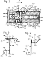
- einen Schnitt entlang der Linie A-A aus
Fig. 1 ; - Fig. 3
- eine vergrößerte Ansicht des Kastenblechs des ersten Feuerschutztürflügels aus
Fig. 2 ; - Fig. 4
- eine vergrößerte Ansicht des Kastenblechs des zweiten Feuerschutztürflügels aus
Fig. 2 ; - Fig. 5
- ein weiteres Ausführungsbeispiel eines Feuerschutztürflügels;
- Fig. 6
- eine vergrößerte Ansicht des Kastenblechs des Feuerschutztürflügels aus
Fig. 5 ; - Fig. 7
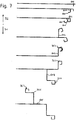
- eine Kantfolge zum Herstellen des Kastenblechs aus
Fig. 6 ; - Fig. 8
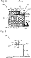
- ein weiteres Ausführungsbeispiel eines Feuerschutztürflügels;
- Fig. 9
- eine vergrößerte Ansicht des Kastenblechs des Feuerschutztürflügels aus
Fig. 8 ; und - Fig. 10
- eine Kantfolge zum Herstellen des Kastenblechs aus
Fig. 9 . - Gemäß
Fig. 1 umfasst eine Mehrflügel-Feuerschutztür 10 eine Zarge 11 einen Standflügel 12 sowie einen Gangflügel 13. - Der Standflügel 12 ist mittels Türbändern 16 um eine erste Hochachse 14 schwenkbar an der Zarge 11 befestigt. Der Gangflügel 13 ist mittels Türbändern 16 um eine zweite Hochachse 15 schwenkbar an der Zarge 11 befestigt. Im geschlossenen Zustand erfassen der Standflügel 12 und der Gangflügel 13 einander an einem Mittelstoßbereich 17.
- Die Mehrflügel-Feuerschutztür 10 kann ferner eine Türschwelle 18 umfassen. Der Standflügel 12 kann mit einem Riegelbolzen 19 versehen sein, der den Standflügel 12 an der Zarge 11 oben und der Türschwelle 18 unten verriegelt.
- Der Standflügel 12 weist einen ersten Feuerschutztürflügel 100 auf. Der Gangflügel weist einen zweiten Feuerschutztürflügel 200 auf. Der erste Feuerschutztürflügel 100 und der zweite Feuerschutztürflügel 200 werden im Folgenden anhand der
Figuren 1 bis 4 erläutert. - Der erste Feuerschutztürflügel 100 weist einen ersten Mantel 101 aus Blech, insbesondere Stahlblech, mit einer darin befindlichen Füllung 102 auf.
- An dem ersten Mantel 101 sind eine erste Breitseite 110 und eine zweite Breitseite 112 ausgebildet. Der erste Mantel 101 umfasst ein erstes Deckelblech 103 und ein erstes Kastenblech 104. Die erste Breitseite 110 wird auch Gegenbandseite 120 genannt, wohingegen die zweite Breitseite 112 auch Bandseite 130 genannt wird. Das erste Kastenblech 104 weist die Gegenbandseite 120, eine erste bandseitige Stirnseite 105 und eine erste schlossseitige Stirnseite 106 auf. Das erste Deckelblech 103 weist die Bandseite 130 auf.
- Eine erste Metallverstärkungsplatte 107 kann zum Verstärken der ersten schlossseitigen Stirnseite 106 vorgesehen sein. Die erste Metallverstärkungsplatte 107 kann gleichzeitig als Gegenlagerplatte 108 für ein Verriegelungselement eines Türschlosses, wie etwa einen Schnäpper 209, dienen.
- Das erste Kastenblech 104 ist an der Gegenbandseite 120 zu einem gegenbandseitigen Vorsprung 121 gebogen. Der gegenbandseitige Vorsprung 121 ist vorzugsweise aus einer Doppellage des ersten Kastenblechs 104 gebildet. Der gegenbandseitige Vorsprung 121 verläuft unter einem Winkel zu der Gegenbandseite 120 in Richtung auf die Bandseite 130. Der gegenbandseitige Vorsprung 121 kann auch im Wesentlichen parallel zu der ersten schlossseitigen Stirnseite 106 verlaufen.
- Im Weiteren verläuft das erste Kastenblech 104 in Richtung auf die erste bandseitige Stirnseite 105, so dass vorzugsweise eine Doppellage gebildet ist. Das erste Kastenblech 104 ist dann zurückgebogen und verläuft in einem Abstand zu der Doppellage. Dadurch ist ein Hohlkammerprofil 124 gebildet. Das Hohlkammerprofil 124 ist im Wesentlichen U-förmig ausgebildet und zu der ersten schlossseitigen Stirnseite 106 hin geöffnet.
- Das erste Kastenblech 104 verläuft anschließend von der Gegenbandseite 120 zu der Bandseite 130 und bildet so die erste schlossseitige Stirnseite 106. Ein bandseitiger Rücksprung 131 grenzt an die erste schlossseitige Stirnseite 106.
- Der bandseitige Rücksprung 131 ist als ein erstes Nutprofil 132 ausgebildet. Das erste Nutprofil 132 ist vorzugsweise im Wesentlichen U-förmig ausgebildet.
- Das erste Nutprofil 132 umfasst einen ersten Vorsprung 133, der eine erste Nutflanke 134 bildet, und im Wesentlichen parallel zu der ersten schlossseitigen Stirnseite 106 in Richtung auf die Bandseite 130 vorspringt, einen ersten Nutgrund 135, der im Wesentlichen parallel zu der ersten Breitseite 110 verläuft, sowie eine erste Umbiegung 136, an der das erste Deckelblech 103 und das erste Kastenblech 104 miteinander verhakt sind.
- Auf der Gegenbandseite 120 ist eine Führungseinrichtung 150 vorgesehen. Die Führungseinrichtung 150 umfasst einen Schlitz 151 und eine daran angrenzende Hohlkammer 152. Die Hohlkammer 152 ist durch das Hohlkammerprofil 124 begrenzt.
- Auf der Gegenbandseite 120 ist eine Verhakeinrichtung 140 vorgesehen. Die Verhakeinrichtung 140 umfasst ein Erfassungselement 141. Das Erfassungselement 141 weist einen Erfassungsabschnitt 142 und einen Befestigungsabschnitt 143 auf. Der Befestigungsabschnitt 143 ist durch den Schlitz 151 in die Hohlkammer 152 eingesteckt. Das Erfassungselement 141 ist so angeordnet, dass es in eine Aussparung, einen Rücksprung oder dergleichen eines anderen Feuerschutztürflügels eingreifen kann.
- Ferner umfasst der erste Feuerschutztürflügel 100 eine Bewegungsbegrenzungseinrichtung 160, welche die Bewegung des Erfassungselements 141 begrenzt. Die Bewegungsbegrenzungseinrichtung 160 weist einen ersten Begrenzungsabschnitt 161 und einen zweiten Begrenzungsabschnitt 162 auf. Bei dem ersten Feuerschutztürflügel 100 ist der erste Begrenzungsabschnitt 161 an dem Erfassungsabschnitt 142 angeordnet. Der zweite Begrenzungsanschnitt 162 ist an dem gegenbandseitigen Vorsprung 121 angeordnet.
- Der zweite Feuerschutztürflügel 200 ist ähnlich wie der erste Feuerschutztürflügel 100 aufgebaut. Der zweite Feuerschutztürflügel 200 weist einen zweiten Mantel 201 aus Blech, insbesondere Stahlblech, und eine darin befindliche Füllung 202 auf.
- Der zweite Mantel 201 weist ebenfalls die erste Breitseite 110 und die zweite Breitseite 112 auf. Der zweite Mantel 201 umfasst ein zweites Deckelblech 203 und ein zweites Kastenblech 204. Das zweite Kastenblech 204 weist die Gegenbandseite 120, eine zweite bandseitige Stirnseite 205 und eine zweite schlossseitige Stirnseite 206 auf. Das zweite Deckelblech 203 weist die Bandseite 130 auf.
- Das zweite Kastenblech 204 umfasst eine zweite bandseitige Stirnseite 205 und eine zweite schlossseitige Stirnseite 206. Die zweite schossseitige Stirnseite 206 kann mit einer zweiten Metallverstärkungsplatte 207 versehen sein. Der zweite Feuerschutztürflügel 200 umfasst ein Standardschloss 208, das einen Schnäpper 209 aufweist. Der Schnäpper 209 stützt den zweiten Feuerschutztürflügel 200 beispielsweise an der Gegenlagerplatte 108 des ersten Feuerschutztürflügels 100.
- Der zweite Feuerschutztürflügel 200 umfasst einen gegenbandseitigen Rücksprung 220. Der gegenbandseitige Rücksprung 220 ist vorzugsweise als ein im Wesentlichen U-förmiges zweites Nutprofil 221 ausgebildet.
- Das zweite Nutprofil 221 hat eine aus dem zweiten Kastenblech 204 gebildete zweite Nutflanke 222, die vorzugsweise unter einem Winkel von 45° zu der Gegenbandseite 120 verläuft. Angrenzend an die zweite Nutflanke 222 befindet sich ein zweiter Nutgrund 223, der im Wesentlichen parallel zu der Gegenbandseite 120 verläuft. Daran anschließend ist ein zweiter Vorsprung 224 gebildet, der im Wesentlichen parallel zu der zweiten schlossseitigen Stirnseite 206 in Richtung auf die Gegenbandseite 120 vorspringt. Die zweite schlossseitige Stirnseite 206 verläuft im Wesentlichen senkrecht zu den Breitseiten 110, 112 von der Gegenbandseite 120 zu der Bandseite 130.
- Der zweite Feuerschutztürflügel 200 umfasst ferner ein bandseitiges Nutprofil 231. Das bandseitige Nutprofil 231 ist vorzugsweise im Wesentlichen U-förmig ausgebildet, wobei die Öffnung der Gegenbandseite 120 zugewandt ist.
- Das bandseitige Nutprofil 231 umfasst eine bandseitige Nutflanke 232, einen bandseitigen Nutgrund 233 und eine bandseitige Umbiegung 234.
- Ein Abschnitt des zweiten Kastenblechs 204 bildet die bandseitige Nutflanke 232, die in den bandseitigen Nutgrund 233 übergeht und abschließend die bandseitige Umbiegung 234 bildet. Der bandseitige Nutgrund 233 verläuft im Wesentlichen parallel zu der Bandseite 130. Die bandseitige Umbiegung 234 bildet einen von der Bandseite 130 auf die Gegenbandseite 120 vorspringenden Vorsprung.
- Das zweite Nutprofil 221 und das bandseitige Nutprofil 231 sind Beispiele für weitere Türelemente, die mit der Verhakeinrichtung 140 verhaken können.
- Wie am besten aus
Fig. 2 erkennbar, greift das Erfassungselement 141 im geschlossenen Zustand der Mehrflügel-Feuerschutztür 10 in das zweite Nutprofil 221 ein. Wenn sich im Brandfall die beiden Feuerschutztürflügel 100, 200 zu verformen beginnen, können der Erfassungsabschnitt 142 und der zweite Vorsprung 224 verhaken. Dadurch entsteht eine Zugkraft F, die von der ersten schlossseitigen Stirnseite 106 weg auf die zweite bandseitige Stirnseite 205 gerichtet ist und auf das Erfassungselement 141 wirkt. Das Erfassungselement 141 wird somit im Wesentlichen parallel zu der ersten Breitseite 110, genauer der Gegenbandseite 120, bewegt. Die auf die Feuerschutztürflügel 100, 200 wirkenden Biegekräfte können durch diese kontrollierte Bewegung verringert werden. - Die Bewegungsbegrenzungseinrichtung 160 verhindert, dass sich das Erfassungselement 141 von dem ersten Feuerschutztürflügel 100 löst. Das Erfassungselement 141 kann sich innerhalb eines Bewegungsbereiches 122, wie er durch die Bewegungsbegrenzungseinrichtung 160 vorgegeben ist, bewegen. Wenn das Erfassungselement 141 durch die Zugkraft F weit genug ausgezogen wird, stößt der erste Begrenzungsabschnitt 161 an den zweiten Begrenzungsabschnitt 162. Die der ersten schlossseitigen Stirnseite 106 zugewandte Seite des ersten Vorsprungs 121 bildet daher einen Anschlagabschnitt 123 für das Erfassungselement 141. Die Biegekräfte werden dann beispielsweise über den ersten Vorsprung 121 und die Gegenbandseite 120 abgeleitet.
- Sollte zwischen der ersten schlossseitigen Stirnseite 106 und der zweiten schlossseitigen Stirnseite 205 ein Spaltbereich entstehen, kann der Spaltbereich durch das in eine ausgefahrene Position bewegte Erfassungselement 141 abgedeckt werden, so dass ein Durchtreten von Rauch- und Brandgasen durch die Mehrflügel-Feuerschutztür 10 verhindert werden kann.
- Anhand der
Figuren 5 und 6 wird ein weiteres Ausführungsbeispiel eines ersten Feuerschutztürflügels 300 erläutert. - Der erste Feuerschutztürflügel 300 umfasst ersten Mantel 301 aus Blech, insbesondere Stahlblech, und eine darin befindliche Füllung 302. An dem ersten Mantel 301 sind eine erste Breitseite 310 und eine zweite Breitseite 312 ausgebildet. Der erste Mantel 301 umfasst ein erstes Deckelblech 303 und ein erstes Kastenblech 304. Die erste Breitseite 310 wird auch Gegenbandseite 320 genannt, wohingegen die zweite Breitseite 312 auch Bandseite 330 genannt wird. Das erste Kastenblech 304 weist die Bandseite 330 und eine erste schlossseitige Stirnseite 306 auf.
- Das erste Deckelblech 303 weist die Gegenbandseite 320 auf.
- An der ersten schlossseitigen Stirnseite 306 kann, wie bei dem vorigen Ausführungsbeispiel, eine erste Metallverstärkungsplatte 307 angeordnet sein. Die erste Metallverstärkungsplatte 307 kann auch als Gegenlagerplatte 308 fungieren. Das erste Kastenblech 304 bildet zunächst zusammen mit dem ersten Deckelblech 303 eine Umbiegung 321. Von der Umbiegung 321 verläuft das erste Kastenblech 304 in einer Doppellage mit dem ersten Deckelblech 303. Das erste Kastenblech 304 verläuft weiter in Dickenrichtung auf die Bandseite 330 zu und verläuft im Weiteren parallel zu der Gegenbandseite 320, so dass ein Hohlkammerprofil 324 gebildet ist.
- Das erste Kastenblech 304 ist an einer Kante 325 in Richtung auf die Bandseite 330 gebogen und bildet die erste schlossseitige Stirnseite 306.
- Das erste Kastenblech 304 hat auf der Bandseite 330 einen bandseitigen Rücksprung 331. Der erste bandseitige Rücksprung 331 ist vorzugsweise als ein Nutprofil 332 ausgebildet. Das Nutprofil 332 weist einen Vorsprung 333, eine Nutflanke 334 und einen Nutgrund 335 auf. Der Vorsprung 333 verläuft unter einem Winkel zu der Bandseite 330 von der ersten Bandseite 330 in Richtung auf die erste schlossseitige Stirnseite 306.
- Das erste Kastenblech 304 umfasst eine durch den ersten bandseitigen Rücksprung 331 gebildete Dichtungsaufnahme 337. In der Dichtungsaufnahme 337 kann eine Dichtung 338 aufgenommen sein.
- Eine Verhakeinrichtung 340 ist auf der Gegenbandseite 320 vorgesehen. Die Verhakeinrichtung 340 umfasst ein Erfassungselement 341, das einen Erfassungsabschnitt 342 und einen Befestigungsabschnitt 343 aufweist. Der Erfassungsabschnitt 341 ist als ein Vorsprung 326 ausgebildet, der in einem Bereich in der Nähe der Kante 325 in Richtung auf die Gegenbandseite 320 vorspringt. Der Erfassungsabschnitt 342 kann, wie bei dem vorigen Ausführungsbeispiel ein weiteres Türelement, wie etwa einen anderen Vorsprung, einen Rücksprung, ein Nutprofil oder dergleichen erfassen.
- Der Befestigungsabschnitt 343 ist in eine Führungseinrichtung 350 eingesteckt. Die Führungseinrichtung 350 umfasst einen zwischen der ersten gegenbandseitigen Umbiegung 321 und einen gegenüberliegenden Abschnitt des Kastenblechs 304 gebildeten Schlitz 351. Die Führungseinrichtung 350 umfasst weiter eine an dem Schlitz 351 angrenzende Hohlkammer 352 die durch das Hohlkammerprofil 324 begrenzt ist.
- Weiter ist eine Bewegungsbegrenzungseinrichtung 360 vorgesehen. Die Bewegungsbegrenzungseinrichtung 360 umfasst einen ersten Begrenzungsabschnitt 361, der an den Befestigungsabschnitt 343 angrenzt und in Dickenrichtung zu der Gegenbandseite 320 verläuft. Die Bewegungsbegrenzungseinrichtung 360 umfasst ferner einen zweiten Begrenzungsabschnitt 362, der von der Umbiegung 321 gebildet wird. Das erste Deckelblech 303 bildet einen in die Hohlkammer 352 aufgenommenen Anschlagabschnitt 323. Ein Bewegungsbereich 322 wird durch die Hohlkammer 352 und den Anschlagabschnitt 323 definiert. Das Erfassungselement 341 kann sich also nur innerhalb des Bewegungsbereiches 322 bewegen.
- Im Brandfall, wenn eine Zugkraft F auf das Erfassungselement 341 wirkt, bewegt sich der Vorsprung 326 in Richtung der Zugkraft F. Das gesamte Erfassungselement 341 wird somit entlang des Bewegungsbereiches 322 in eine ausgefahrene Position bewegt. Die erste Metallverstärkungsplatte 307 stellt eine gewisse Steifigkeit der schlossseitigen Stirnseite 306 sicher, so dass bei gleicher Zugkraft F im Vergleich zu dem vorigen Ausführungsbeispiel die Auslenkung des Erfassungselements 341 geringer ist.
- Ein eventuell zwischen dem ersten Feuerschutztürflügel 300 und dem weiteren Türelement auftretender Spaltbereich kann daher besser zusammengezogen und in seiner Breite verringert werden.
- Anhand der
Fig. 7 wird nun ein Herstellungsverfahren für das erste Kastenblech 304 erläutert. - Aus einem Blech, insbesondere Stahlblech, wird in einem Schritt ein erster Hohlprofilabschnitt 600 gebogen. Der erste Hohlprofilabschnitt 600 ist in einem Winkel von etwa 90° in eine erste Richtung D1 gebogen.
- In einem weiteren Schritt wird ein zweiter Hohlprofilabschnitt 601 gebogen, der im Wesentlichen senkrecht zu dem ersten Hohlprofilabschnitt 600 verläuft und ebenfalls in die erste Richtung D1 gebogen wird. Der zweite Hohlprofilabschnitt 601 ist länger als der erste Hohlprofilabschnitt 600.
- In einem weiteren Schritt wird ein dritter Hohlprofilabschnitt 602 gebildet. Der dritte Hohlprofilabschnitt 602 wird ebenfalls in die erste Richtung D1 gebogen, jedoch lediglich um 70°. Der dritte Hohlprofilabschnitt 602 ist als der erste Hohlprofilabschnitt 601.
- In einem weiteren Schritt wird ein gegenbandseitiger Kantenabschnitt 603 gebogen. Der gegenbandseitige Kantenabschnitt 603 wird in eine zweite Richtung D2 gebogen, die der ersten Richtung D1 entgegengesetzt ist.
- In einem weiteren Schritt wird der dritte Hohlprofilabschnitt 602 weiter in die erste Richtung D1 gebogen, so dass er im Wesentlichen senkrecht zu den gegenbandseitigen Kantenabschnitt 603 verläuft. Der erste, zweite und dritte Hohlprofilabschnitt 600, 601, 603 bilden dadurch das Hohlkammerprofil 324.
- In einem weiteren Schritt wird ein schlossseitiger Stirnseitenabschnitt 604 gebildet. Der schlossseitige Stirnseitenabschnitt 604 wird durch Biegen in die erste Richtung D1 um etwa 90° gebildet. Der schlossseitige Stirnseitenabschnitt 604 bildet die erste schlossseitige Stirnseite 306 des ersten Feuerschutztürflügels 300.
- In einem weiteren Schritt wird ein bandseitiger Doppellagenabschnitt 605 gebildet, in dem das Blech in die zweite Richtung D2 auf sich selbst zurückgebogen wird. Aus dem bandseitigen Doppellagenabschnitt 605 wird später der erste bandseitige Rücksprung 331 gebildet.
- Das so hergestellte erste Kastenblech 304 kann mit dem ersten Deckelblech 303 eingehakt werden. Der so gebildete erste Mantel 301 wird dann mit der Füllung 302 ausgefüllt. Die Verhakeinrichtung 340 kann dann an der ersten schlossseitigen Stirnseite 306 angeordnet und beispielsweise durch Einstecken oder Schrauben montiert werden.
- Anhand der
Figuren 8 und 9 wird ein weiteres Ausführungsbeispiel eines ersten Feuerschutztürflügels 500 erläutert. - Der erste Feuerschutztürflügel 500 umfasst ersten Mantel 501 aus Blech, insbesondere Stahlblech, und eine darin befindliche Füllung 502. An dem ersten Mantel 501 sind eine erste Breitseite 510 und eine zweite Breitseite 512 ausgebildet.
- Der erste Mantel 501 umfasst ein erstes Deckelblech 503 und ein erstes Kastenblech 504. Die erste Breitseite 510 wird auch Gegenbandseite 520 genannt, wohingegen die zweite Breitseite 512 auch Bandseite 530 genannt wird. Das erste Kastenblech 504 weist die Gegenbandseite 520 und eine erste schlossseitige Stirnseite 506 auf. Das erste Deckelblech 503 weist die Bandseite 530 auf.
- Wie bei den vorigen Ausführungsbeispielen kann die erste schlossseitige Stirnseite 506 eine erste Metallverstärkungsplatte 507 umfassen. Die erste Metallverstärkungsplatte 507 kann als Gegenlagerplatte 508 fungieren.
- Auf der ersten Gegenbandseite 520 sind das erste Deckelblech 503 und das erste Kastenblech 504 an einer Umbiegung 521 verhakt. Das erste Kastenblech 504 verläuft angrenzend an die Umbiegung 521 im Wesentlichen parallel zu der Gegenbandseite 520 in Richtung der bandseitigen Stirnseite (nach links in
Fig. 8 ) des Feuerschutztürflügels 500. Das erste Kastenblech 504 ist im Weiteren auf sich selbst zurückgebogen, so dass ein Hohlkammerprofil 524 gebildet wird. Das Hohlkammerprofil 524 hat im Wesentlichen U-Form. Das erste Kastenblech 504 erstreckt sich weiter bis zu einer Kante 525, an der das erste Kastenblech 504 zum Bilden der ersten schlossseitigen Stirnseite 506 in Richtung auf die Bandseite 530 gebogen ist. - Das erste Kastenblech 504 umfasst eine durch den ersten bandseitigen Rücksprung 531 gebildete Dichtungsaufnahme 537. In der Dichtungsaufnahme 537 kann eine Dichtung 338 aufgenommen sein.
- Ferner ist auf der ersten Gegenbandseite 520 eine Verhakeinrichtung 540 vorgesehen. Die Verhakeinrichtung 540 umfasst ein Erfassungselement 541, das einen Erfassungsabschnitt 542 zum Erfassen eines weiteren Türelements sowie eine Befestigungsabschnitt 543 aufweist. Der Erfassungsabschnitt 541 ist als ein Vorsprung 526 ausgebildet, der in einem Bereich in der Nähe der Kante 525 in Richtung auf die Gegenbandseite 520 vorspringt. Der Erfassungsabschnitt 541 kann, wie bei dem vorigen Ausführungsbeispiel ein weiteres Türelement, wie etwa einen anderen Vorsprung, einen Rücksprung, ein Nutprofil oder dergleichen erfassen.
- Der Befestigungsabschnitt 543 ist in das Hohlkammerprofil 524 eingesteckt. Das Hohlkammerprofil 524 bildet dadurch eine Führungseinrichtung 550, die einen Schlitz 551 und eine Hohlkammer 552 umfasst. Der Schlitz 551 wird durch Umbiegung 521 und den gegenüberliegenden Abschnitt des ersten Kastenbleches 504 gebildet. Die Hohlkammer 552 erstreckt sich angrenzend an den Schlitz 551 und von dem Schlitz 551 weg parallel zu den Breitseiten 510, 512 in Richtung auf die bandseitige Stirnseite.
- Im Unterschied zu den vorigen Ausführungsbeispielen weist der erste Feuerschutztürflügel 500 keine Bewegungsbegrenzungseinrichtung auf. Stattdessen ist das Erfassungselement 541 derart ausgebildet, dass sich der Befestigungsabschnitt 543 auch im ausgefahrenen Zustand des Erfassungselements 541 immer noch in der Führungseinrichtung 550 befindet. Die Führungseinrichtung 550 definiert so einen Bewegungsbereich 522, in dem sich das Erfassungselement 541 bewegen kann.
- Im Brandfall kann das Erfassungselement durch eine Zugkraft F aus seiner normalen Position in eine ausgefahrene Position bewegt werden. Durch die erste Metallverstärkungsplatte 507 wirkt eine größere rücktreibende Kraft auf das Erfassungselement 541. Nachfolgend wird anhand von
Fig. 10 ein Herstellverfahren für das erste Kastenblech 504 angegeben. - Ein Metallblech wird in einem Schritt zu einem gegenbandseitigen Umbiegungsabschnitt 612 gebogen. Die Biegung erfolgt in eine erste Richtung D1.
- In einem weiteren Schritt wird der gegenbandseitige Umbiegungsabschnitt um etwa 90° in eine zweite Richtung D2, die der ersten Richtung D1 entgegengesetzt ist, gebogen. Dadurch ist die erste gegenbandseitige Umbiegung 521 teilweise gebildet.
- In einem weiteren Schritt wird das Blech um etwa 110° in die erste Richtung D1 gebogen und so ein erster Hohlprofilabschnitt 610 und ein zweiter Hohlprofilabschnitt 611 gebildet.
- In einem weiteren Schritt wird ein gegenbandseitiger Kantenabschnitt 603 in die zweite Richtung D2 gebogen und so die erste gegenbandseitige Kante 525 gebildet.
- In einem weiteren Schritt wird der erste Hohlprofilabschnitt 610 weiter gebogen, so dass er parallel in einem Abstand zu dem zweiten Hohlprofilabschnitt 611 verläuft. Dadurch ist das Hohlkammerprofil 524 gebildet, das später als Führungseinrichtung 550 dient.
- In einem weiteren Schritt wird ein schlossseitiger Stirnseitenabschnitt 614 in die erste Richtung D1 gebogen, so dass dieser im Wesentlichen senkrecht zu dem noch unbearbeiteten Abschnitt des Metallblechs verläuft.
- Durch Zurückbiegen des Bleches wird in einem weiteren Schritt ein bandseitiger Doppellagenabschnitt 615 gebildet, der zum Bilden des ersten bandseitigen Rücksprungs 531 dient. Der schlossseitige Stirnseitenabschnitt 614 bildet dann die erste schlossseitige Stirnseite 506.
- Gemäß der vorliegenden Erfindung wurden Feuerschutztürflügel angegeben, die im Brandfall eine gewisse Verformung erfahren und dabei auftretende Spalte verschlossen halten, so dass ein Durchtreten von Brand- und Heißgasen durch den Feuerschutztürflügel und die damit gebildete Feuerschutztür verhindert werden kann. Zudem wurden einfache Herstellungsverfahren für Kastenbleche für derartige Feuerschutztürflügel dargestellt.
-
- 10
- Mehrflügel-Feuerschutztür
- 11
- Zarge
- 12
- Standflügel
- 13
- Gangflügel
- 14
- erste Hochachse
- 15
- zweite Hochachse
- 16
- Türband
- 17
- Mittelstoßbereich
- 18
- Türschwelle
- 19
- Riegelbolzen
- 100
- erster Feuerschutztürflügel
- 101
- erster Mantel
- 102
- Füllung
- 103
- erstes Deckelblech
- 104
- erstes Kastenblech
- 105
- erste bandseitige Stirnseite
- 106
- erste schlossseitige Stirnseite
- 107
- erste Metallverstärkungsplatte
- 108
- Gegenlagerplatte
- 110
- erste Breitseite
- 112
- zweite Breitseite
- 120
- Gegenbandseite
- 121
- gegenbandseitiger Vorsprung
- 122
- Bewegungsbereich
- 123
- Anschlagabschnitt
- 124
- Hohlkammerprofil
- 130
- Bandseite
- 131
- bandseitiger Rücksprung
- 132
- erstes Nutprofil
- 133
- erster Vorsprung
- 134
- erste Nutflanke
- 135
- erster Nutgrund
- 136
- erste Umbiegung
- 140
- Verhakeinrichtung
- 141
- Erfassungselement
- 142
- Erfassungsabschnitt
- 143
- Befestigungsabschnitt
- 150
- Führungseinrichtung
- 151
- Schlitz
- 152
- Hohlkammer
- 160
- Bewegungsbegrenzungseinrichtung
- 161
- erster Begrenzungsabschnitt
- 162
- zweiter Begrenzungsabschnitt
- 200
- zweiter Feuerschutztürflügel
- 201
- zweiter Mantel
- 202
- Füllung
- 203
- zweites Deckelblech
- 204
- zweites Kastenblech
- 205
- zweite bandseitige Stirnseite
- 206
- zweite schlossseitige Stirnseite
- 207
- zweite Metallverstärkungsplatte
- 208
- Standardschloss
- 209
- Schnäpper
- 220
- gegenbandseitiger Rücksprung
- 221
- zweites Nutprofil
- 222
- zweite Nutflanke
- 223
- zweiter Nutgrund
- 224
- zweiter Vorsprung
- 231
- bandseitiges Nutprofil
- 232
- bandseitige Nutflanke
- 233
- bandseitiger Nutgrund
- 234
- bandseitige Umbiegung
- 300
- erster Feuerschutztürflügel
- 301
- erster Mantel
- 302
- Füllung
- 303
- erstes Deckelblech
- 304
- erstes Kastenblech
- 306
- erste schlossseitige Stirnseite
- 307
- erste Metallverstärkungsplatte
- 308
- Gegenlagerplatte
- 310
- erste Breitseite
- 312
- zweite Breitseite
- 320
- Gegenbandseite
- 321
- Umbiegung
- 322
- Bewegungsbereich
- 323
- Anschlagabschnitt
- 324
- Hohlkammerprofil
- 325
- Kante
- 326
- Vorsprung
- 330
- Bandseite
- 331
- bandseitiger Rücksprung
- 332
- Nutprofil
- 333
- Vorsprung
- 334
- Nutflanke
- 335
- Nutgrund
- 337
- Dichtungsaufnahme
- 338
- Dichtung
- 340
- Verhakeinrichtung
- 341
- Erfassungselement
- 342
- Erfassungsabschnitt
- 343
- Befestigungsabschnitt
- 350
- Führungseinrichtung
- 351
- Schlitz
- 352
- Hohlkammer
- 360
- Bewegungsbegrenzungseinrichtung
- 361
- erster Begrenzungsabschnitt
- 362
- zweiter Begrenzungsabschnitt
- 500
- erster Feuerschutztürflügel
- 501
- erster Mantel
- 502
- Füllung
- 503
- erstes Deckelblech
- 504
- erstes Kastenblech
- 506
- erste schlossseitige Stirnseite
- 507
- erste Metallverstärkungsplatte
- 508
- Gegenlagerplatte
- 510
- erste Breitseite
- 512
- zweite Breitseite
- 520
- Gegenbandseite
- 521
- Umbiegung
- 522
- Bewegungsbereich
- 524
- Hohlkammerprofil
- 525
- Kante
- 526
- Vorsprung
- 530
- Bandseite
- 531
- bandseitiger Rücksprung
- 537
- Dichtungsaufnahme
- 538
- Dichtung
- 540
- Verhakeinrichtung
- 541
- Erfassungselement
- 542
- Erfassungsabschnitt
- 543
- Befestigungsabschnitt
- 550
- Führungseinrichtung
- 551
- Schlitz
- 552
- Hohlkammer
- 600
- erster Hohlprofilabschnitt
- 601
- zweiter Hohlprofilabschnitt
- 602
- dritter Hohlprofilabschnitt
- 603
- gegenbandseitiger Kantenabschnitt
- 604
- schlossseitiger Stirnseitenabschnitt
- 605
- bandseitiger Doppellagenabschnitt
- 610
- erster Hohlprofilabschnitt
- 611
- zweiter Hohlprofilabschnitt
- 612
- gegenbandseitiger Umbiegungsabschnitt
- 613
- gegenbandseitiger Kantenabschnitt
- 614
- schlossseitiger Stirnseitenabschnitt
- 615
- bandseitiger Doppellagenabschnitt
- D1
- erste Richtung
- D2
- zweite Richtung
- F
- Zugkraft
Claims (10)
- Feuerschutztürflügel (100, 200, 300, 500) für eine Feuerschutztür (10), wobei der Feuerschutztürflügel (100, 200, 300, 500) wenigstens ein Mantelblech (101, 201, 301, 501) und eine Füllung (102) aufweist, wobei eine an dem Mantelblech (101, 201, 301, 501) angeordnete Verhakeinrichtung (140, 340, 540) im geschlossenen Zustand der Feuerschutztür (10) stets ein weiteres Türelement der Feuerschutztür (10) hintergreift, wobei die Verhakeinrichtung (140, 340, 540) ein aus Metall gebildetes Erfassungselement (141, 341, 541) zum Erfassen des weiteren Türelements aufweist, wobei das Erfassungselement (141, 341, 541) derart ausgebildet ist, dass das Erfassungselement (141, 341, 541) im Brandfall mit dem weiteren Türelement verhakt, dadurch gekennzeichnet, dass aufgrund der Verhakung eine Zugkraft (F) derart wirkt, dass das Erfassungselement (141, 341, 541) von einer Normalposition in eine ausgefahrene Position bewegt wird.
- Feuerschutztürflügel (100, 200, 300, 500) nach Anspruch 1, dadurch gekennzeichnet, dass das Erfassungselement (141, 341, 541) einen Erfassungsabschnitt (142, 342, 542) zum Hintergreifen des weiteren Türelements und einen in eine Führungseinrichtung (150, 350, 550) eingesteckten Befestigungsabschnitt (143, 343, 543) aufweist.
- Feuerschutztürflügel (100, 200, 300, 500) nach Anspruch 2, dadurch gekennzeichnet, dass die Führungseinrichtung (150, 350, 550) einen Schlitz (151, 351, 551) aufweist, in welchem der Befestigungsabschnitt (143, 343, 543), insbesondere kraftschlüssig, eingesteckt ist.
- Feuerschutztürflügel (100, 200, 300, 500) nach Anspruch 2 oder 3, dadurch gekennzeichnet, dass das Erfassungselement (141, 341, 541) an die Führungseinrichtung (150, 350, 550) derart angepasst ist, dass das Erfassungselement (141, 341, 541) auch in der ausgefahrenen Position in der Führungseinrichtung (150, 350, 550) gehalten ist.
- Feuerschutztürflügel (100, 200, 300, 500) nach einem der Ansprüche 2 bis 4, dadurch gekennzeichnet, dass der Erfassungsabschnitt (142, 342, 542) und der Befestigungsabschnitt (143, 343, 543) im Wesentlichen orthogonal zueinander verlaufen.
- Feuerschutztürflügel (100, 200, 300, 500) nach einem der Ansprüche 1 bis 5, gekennzeichnet durch eine Bewegungsbegrenzungseinrichtung (160, 360) zum Begrenzen der Bewegung des Erfassungselements (141, 341).
- Feuerschutztürflügel (100, 200, 300, 500) nach Anspruch 6, dadurch gekennzeichnet, dass die Bewegungsbegrenzungseinrichtung (160, 360) einen an dem Erfassungselement (141, 341) angeordneten und an dessen Befestigungsabschnitt (143, 343) angrenzenden ersten Begrenzungsabschnitt (161, 361) und einen, insbesondere aus dem Mantelblech (101, 301) gebildeten, zweiten Begrenzungsabschnitt (162, 362) aufweist.
- Feuerschutztürflügel (100, 200, 300, 500) nach Anspruch 7, dadurch gekennzeichnet, dass der erste Begrenzungsabschnitt (161, 361) im Wesentlichen orthogonal zu dem Befestigungsabschnitt (143, 343) und im Wesentlichen parallel zu dem Erfassungsabschnitt (142, 342), insbesondere in die gleiche Richtung wie der Erfassungsabschnitt (142, 342), verläuft.
- Feuerschutztürflügel (100, 200, 300, 500) nach einem der Ansprüche 1 bis 8, dadurch gekennzeichnet, dass die Verhakeinrichtung (140, 340, 540) entlang seiner gesamten Höhe gebildet ist.
- Mehrflügel-Feuerschutztür (10) gekennzeichnet durch einen um eine erste Hochachse (14) schwenkbaren ersten Feuerschutztürflügel (100, 300, 500) nach einem der Ansprüche 1 bis 9 und einen um eine zweite Hochachse (15) schwenkbaren zweiten Feuerschutztürflügel (200), der wenigstens ein Mantelblech (201) und eine Füllung (102) aufweist, wobei die beiden Feuerschutztürflügel (100, 200, 300, 500) einander im geschlossenen Zustand erfassen, wobei die Verhakeinrichtung (140, 340, 540) das wenigstens eine Mantelblech (201) des zweiten Feuerschutztürflügels (200) im geschlossenen Zustand hintergreift oder verhakt.
Priority Applications (1)
| Application Number | Priority Date | Filing Date | Title |
|---|---|---|---|
| PL14189452T PL2878754T3 (pl) | 2013-11-27 | 2014-10-17 | Skrzydło do jednoskrzydłowych i wieloskrzydłowych drzwi przeciwpożarowych |
Applications Claiming Priority (1)
| Application Number | Priority Date | Filing Date | Title |
|---|---|---|---|
| DE102013113127.1A DE102013113127B4 (de) | 2013-11-27 | 2013-11-27 | Feuerschutztürflügel für eine Ein- oder Mehrflügelfeuerschutztür sowie Mehrflügel-Feuerschutztür |
Publications (2)
| Publication Number | Publication Date |
|---|---|
| EP2878754A1 EP2878754A1 (de) | 2015-06-03 |
| EP2878754B1 true EP2878754B1 (de) | 2020-07-08 |
Family
ID=51730431
Family Applications (1)
| Application Number | Title | Priority Date | Filing Date |
|---|---|---|---|
| EP14189452.7A Active EP2878754B1 (de) | 2013-11-27 | 2014-10-17 | Feuerschutztürflügel für eine ein- oder mehrflügel-Feuerschutztür |
Country Status (4)
| Country | Link |
|---|---|
| EP (1) | EP2878754B1 (de) |
| DE (1) | DE102013113127B4 (de) |
| ES (1) | ES2812571T3 (de) |
| PL (1) | PL2878754T3 (de) |
Families Citing this family (2)
| Publication number | Priority date | Publication date | Assignee | Title |
|---|---|---|---|---|
| JP6787718B2 (ja) * | 2016-07-28 | 2020-11-18 | 三和シヤッター工業株式会社 | 両開き戸の扉体構造 |
| IT201700013365A1 (it) * | 2017-06-08 | 2018-12-08 | Antonio Diez | Porta antieffrazione ad ante girevoli |
Family Cites Families (7)
| Publication number | Priority date | Publication date | Assignee | Title |
|---|---|---|---|---|
| DE1683420B2 (de) * | 1967-02-06 | 1976-05-26 | Felix Fiand GmbH, 5450 Neuwied; Stahl-Schanz KG, 6052 Mühlheim; Türenwerke Riexinger GmbH & CoKG, 7129 Hausen | Tuerelement fuer feuer- und/oder gasschutzzwecke |
| SE455515B (sv) * | 1986-11-24 | 1988-07-18 | Dahlstedt & Johansson Ab | Anordning vid metalldorrar innefattande tva platar pa inbordes avstand |
| DE4136155A1 (de) * | 1991-11-04 | 1993-05-06 | Dmw Schwarze Gmbh & Co Industrietore Kg, 4800 Bielefeld, De | Schlupftuer |
| AT403498B (de) * | 1994-07-20 | 1998-02-25 | Steba Brandschutztore Ges M B | Fixiereinrichtung für brandschutztüren |
| DE19649443B4 (de) * | 1995-11-28 | 2009-07-09 | Puertas Padilla, S.L. | Feuerschutztür und Verfahren zu ihrer Herstellung |
| IT1401293B1 (it) * | 2010-06-09 | 2013-07-18 | Locher | Porta tagliafuoco a due ante con migliorata resistenza al fuoco. |
| DE202011004674U1 (de) * | 2011-03-31 | 2011-06-09 | H & K Teckentrup KG, 33415 | Brandschutztür |
-
2013
- 2013-11-27 DE DE102013113127.1A patent/DE102013113127B4/de active Active
-
2014
- 2014-10-17 PL PL14189452T patent/PL2878754T3/pl unknown
- 2014-10-17 EP EP14189452.7A patent/EP2878754B1/de active Active
- 2014-10-17 ES ES14189452T patent/ES2812571T3/es active Active
Non-Patent Citations (1)
| Title |
|---|
| None * |
Also Published As
| Publication number | Publication date |
|---|---|
| DE102013113127B4 (de) | 2015-11-26 |
| DE102013113127A1 (de) | 2015-05-28 |
| PL2878754T3 (pl) | 2020-11-30 |
| EP2878754A1 (de) | 2015-06-03 |
| ES2812571T3 (es) | 2021-03-17 |
Similar Documents
| Publication | Publication Date | Title |
|---|---|---|
| EP3495595B1 (de) | Hinterfüllung mit intumeszierendem material | |
| EP1648764B1 (de) | Schiebetür mit einem rahmen und einer führung | |
| EP2617934B1 (de) | Brandschutztüre | |
| DE102010005188A1 (de) | Torblatt für ein Feuerschutzschiebetor mit Schlupftür sowie Herstellverfahren | |
| EP2326784B1 (de) | Hubtor | |
| EP2481871B1 (de) | Einbruchshemmende Flügelanlage | |
| DE102013113127B4 (de) | Feuerschutztürflügel für eine Ein- oder Mehrflügelfeuerschutztür sowie Mehrflügel-Feuerschutztür | |
| DE19916338C2 (de) | Sicherheitsvorrichtung für ein Fenster und Fenster mit einer solchen Sicherheitsvorrichtung | |
| EP2728101B1 (de) | Mehrflügelige Feuerschutztür sowie Feuerschutztürflügel hierfür | |
| EP1724430A2 (de) | Feuerschutztürblatt | |
| EP2058459B1 (de) | Gebäudeabschluss mit Panik-Entriegelungselement in einbruchhemmender Ausführung | |
| EP2171177B1 (de) | Revisionsabdeckung | |
| DE102012110456B4 (de) | Mehrflügelige feuerschutztür | |
| EP4079996B1 (de) | Sicherungsvorrichtung und hebeschiebetür | |
| DE3905886C2 (de) | Feuer- und schallhemmende Tür | |
| DE102013003211B4 (de) | Mehrflügelige Feuerschutztür sowie Feuerschutztürflügel hierfür | |
| DE3712584A1 (de) | Tuer | |
| EP1120538B1 (de) | Einbruchhemmende Rollpanzerführungsschiene | |
| DE102009022827B4 (de) | Brandschutz- und/oder Rauchschutzschiebetür | |
| EP1726769B1 (de) | Schutztür mit Türzarge | |
| AT509785B1 (de) | Einsatzprofil für eine wenigstens seitlich von trägern begrenzte türöffnung | |
| EP0782657B2 (de) | Feuerschutz-tür | |
| AT505570B1 (de) | Zarge mit falz für zumindest einen flügel | |
| EP2690244A1 (de) | Fenster- oder Türenelement mit einer zusätzlichen Sicherung gegen gewaltsames Aufbrechen | |
| DE9409916U1 (de) | Sicherheitstür |
Legal Events
| Date | Code | Title | Description |
|---|---|---|---|
| PUAI | Public reference made under article 153(3) epc to a published international application that has entered the european phase |
Free format text: ORIGINAL CODE: 0009012 |
|
| 17P | Request for examination filed |
Effective date: 20141017 |
|
| AK | Designated contracting states |
Kind code of ref document: A1 Designated state(s): AL AT BE BG CH CY CZ DE DK EE ES FI FR GB GR HR HU IE IS IT LI LT LU LV MC MK MT NL NO PL PT RO RS SE SI SK SM TR |
|
| AX | Request for extension of the european patent |
Extension state: BA ME |
|
| R17P | Request for examination filed (corrected) |
Effective date: 20151130 |
|
| RBV | Designated contracting states (corrected) |
Designated state(s): AL AT BE BG CH CY CZ DE DK EE ES FI FR GB GR HR HU IE IS IT LI LT LU LV MC MK MT NL NO PL PT RO RS SE SI SK SM TR |
|
| GRAP | Despatch of communication of intention to grant a patent |
Free format text: ORIGINAL CODE: EPIDOSNIGR1 |
|
| STAA | Information on the status of an ep patent application or granted ep patent |
Free format text: STATUS: GRANT OF PATENT IS INTENDED |
|
| RIC1 | Information provided on ipc code assigned before grant |
Ipc: E06B 3/36 20060101ALI20191129BHEP Ipc: E06B 3/82 20060101ALI20191129BHEP Ipc: E06B 5/16 20060101AFI20191129BHEP Ipc: E06B 3/70 20060101ALN20191129BHEP |
|
| INTG | Intention to grant announced |
Effective date: 20200102 |
|
| RIC1 | Information provided on ipc code assigned before grant |
Ipc: E06B 5/16 20060101AFI20191213BHEP Ipc: E06B 3/82 20060101ALI20191213BHEP Ipc: E06B 3/36 20060101ALI20191213BHEP Ipc: E06B 3/70 20060101ALN20191213BHEP |
|
| GRAS | Grant fee paid |
Free format text: ORIGINAL CODE: EPIDOSNIGR3 |
|
| GRAJ | Information related to disapproval of communication of intention to grant by the applicant or resumption of examination proceedings by the epo deleted |
Free format text: ORIGINAL CODE: EPIDOSDIGR1 |
|
| GRAL | Information related to payment of fee for publishing/printing deleted |
Free format text: ORIGINAL CODE: EPIDOSDIGR3 |
|
| STAA | Information on the status of an ep patent application or granted ep patent |
Free format text: STATUS: REQUEST FOR EXAMINATION WAS MADE |
|
| GRAR | Information related to intention to grant a patent recorded |
Free format text: ORIGINAL CODE: EPIDOSNIGR71 |
|
| STAA | Information on the status of an ep patent application or granted ep patent |
Free format text: STATUS: GRANT OF PATENT IS INTENDED |
|
| GRAA | (expected) grant |
Free format text: ORIGINAL CODE: 0009210 |
|
| STAA | Information on the status of an ep patent application or granted ep patent |
Free format text: STATUS: THE PATENT HAS BEEN GRANTED |
|
| INTC | Intention to grant announced (deleted) | ||
| RIC1 | Information provided on ipc code assigned before grant |
Ipc: E06B 3/36 20060101ALI20200508BHEP Ipc: E06B 3/70 20060101ALN20200508BHEP Ipc: E06B 5/16 20060101AFI20200508BHEP Ipc: E06B 3/82 20060101ALI20200508BHEP |
|
| AK | Designated contracting states |
Kind code of ref document: B1 Designated state(s): AL AT BE BG CH CY CZ DE DK EE ES FI FR GB GR HR HU IE IS IT LI LT LU LV MC MK MT NL NO PL PT RO RS SE SI SK SM TR |
|
| INTG | Intention to grant announced |
Effective date: 20200529 |
|
| REG | Reference to a national code |
Ref country code: AT Ref legal event code: REF Ref document number: 1288628 Country of ref document: AT Kind code of ref document: T Effective date: 20200715 Ref country code: CH Ref legal event code: EP |
|
| REG | Reference to a national code |
Ref country code: DE Ref legal event code: R096 Ref document number: 502014014413 Country of ref document: DE |
|
| REG | Reference to a national code |
Ref country code: IE Ref legal event code: FG4D Free format text: LANGUAGE OF EP DOCUMENT: GERMAN |
|
| REG | Reference to a national code |
Ref country code: LT Ref legal event code: MG4D |
|
| REG | Reference to a national code |
Ref country code: NL Ref legal event code: MP Effective date: 20200708 |
|
| PG25 | Lapsed in a contracting state [announced via postgrant information from national office to epo] |
Ref country code: PT Free format text: LAPSE BECAUSE OF FAILURE TO SUBMIT A TRANSLATION OF THE DESCRIPTION OR TO PAY THE FEE WITHIN THE PRESCRIBED TIME-LIMIT Effective date: 20201109 Ref country code: BG Free format text: LAPSE BECAUSE OF FAILURE TO SUBMIT A TRANSLATION OF THE DESCRIPTION OR TO PAY THE FEE WITHIN THE PRESCRIBED TIME-LIMIT Effective date: 20201008 Ref country code: LT Free format text: LAPSE BECAUSE OF FAILURE TO SUBMIT A TRANSLATION OF THE DESCRIPTION OR TO PAY THE FEE WITHIN THE PRESCRIBED TIME-LIMIT Effective date: 20200708 Ref country code: FI Free format text: LAPSE BECAUSE OF FAILURE TO SUBMIT A TRANSLATION OF THE DESCRIPTION OR TO PAY THE FEE WITHIN THE PRESCRIBED TIME-LIMIT Effective date: 20200708 Ref country code: SE Free format text: LAPSE BECAUSE OF FAILURE TO SUBMIT A TRANSLATION OF THE DESCRIPTION OR TO PAY THE FEE WITHIN THE PRESCRIBED TIME-LIMIT Effective date: 20200708 Ref country code: HR Free format text: LAPSE BECAUSE OF FAILURE TO SUBMIT A TRANSLATION OF THE DESCRIPTION OR TO PAY THE FEE WITHIN THE PRESCRIBED TIME-LIMIT Effective date: 20200708 Ref country code: NO Free format text: LAPSE BECAUSE OF FAILURE TO SUBMIT A TRANSLATION OF THE DESCRIPTION OR TO PAY THE FEE WITHIN THE PRESCRIBED TIME-LIMIT Effective date: 20201008 Ref country code: GR Free format text: LAPSE BECAUSE OF FAILURE TO SUBMIT A TRANSLATION OF THE DESCRIPTION OR TO PAY THE FEE WITHIN THE PRESCRIBED TIME-LIMIT Effective date: 20201009 |
|
| PG25 | Lapsed in a contracting state [announced via postgrant information from national office to epo] |
Ref country code: IS Free format text: LAPSE BECAUSE OF FAILURE TO SUBMIT A TRANSLATION OF THE DESCRIPTION OR TO PAY THE FEE WITHIN THE PRESCRIBED TIME-LIMIT Effective date: 20201108 Ref country code: RS Free format text: LAPSE BECAUSE OF FAILURE TO SUBMIT A TRANSLATION OF THE DESCRIPTION OR TO PAY THE FEE WITHIN THE PRESCRIBED TIME-LIMIT Effective date: 20200708 Ref country code: LV Free format text: LAPSE BECAUSE OF FAILURE TO SUBMIT A TRANSLATION OF THE DESCRIPTION OR TO PAY THE FEE WITHIN THE PRESCRIBED TIME-LIMIT Effective date: 20200708 |
|
| REG | Reference to a national code |
Ref country code: ES Ref legal event code: FG2A Ref document number: 2812571 Country of ref document: ES Kind code of ref document: T3 Effective date: 20210317 |
|
| PG25 | Lapsed in a contracting state [announced via postgrant information from national office to epo] |
Ref country code: NL Free format text: LAPSE BECAUSE OF FAILURE TO SUBMIT A TRANSLATION OF THE DESCRIPTION OR TO PAY THE FEE WITHIN THE PRESCRIBED TIME-LIMIT Effective date: 20200708 |
|
| REG | Reference to a national code |
Ref country code: DE Ref legal event code: R097 Ref document number: 502014014413 Country of ref document: DE |
|
| PG25 | Lapsed in a contracting state [announced via postgrant information from national office to epo] |
Ref country code: SM Free format text: LAPSE BECAUSE OF FAILURE TO SUBMIT A TRANSLATION OF THE DESCRIPTION OR TO PAY THE FEE WITHIN THE PRESCRIBED TIME-LIMIT Effective date: 20200708 Ref country code: RO Free format text: LAPSE BECAUSE OF FAILURE TO SUBMIT A TRANSLATION OF THE DESCRIPTION OR TO PAY THE FEE WITHIN THE PRESCRIBED TIME-LIMIT Effective date: 20200708 Ref country code: EE Free format text: LAPSE BECAUSE OF FAILURE TO SUBMIT A TRANSLATION OF THE DESCRIPTION OR TO PAY THE FEE WITHIN THE PRESCRIBED TIME-LIMIT Effective date: 20200708 Ref country code: CZ Free format text: LAPSE BECAUSE OF FAILURE TO SUBMIT A TRANSLATION OF THE DESCRIPTION OR TO PAY THE FEE WITHIN THE PRESCRIBED TIME-LIMIT Effective date: 20200708 Ref country code: DK Free format text: LAPSE BECAUSE OF FAILURE TO SUBMIT A TRANSLATION OF THE DESCRIPTION OR TO PAY THE FEE WITHIN THE PRESCRIBED TIME-LIMIT Effective date: 20200708 |
|
| PLBE | No opposition filed within time limit |
Free format text: ORIGINAL CODE: 0009261 |
|
| STAA | Information on the status of an ep patent application or granted ep patent |
Free format text: STATUS: NO OPPOSITION FILED WITHIN TIME LIMIT |
|
| PG25 | Lapsed in a contracting state [announced via postgrant information from national office to epo] |
Ref country code: AL Free format text: LAPSE BECAUSE OF FAILURE TO SUBMIT A TRANSLATION OF THE DESCRIPTION OR TO PAY THE FEE WITHIN THE PRESCRIBED TIME-LIMIT Effective date: 20200708 |
|
| REG | Reference to a national code |
Ref country code: CH Ref legal event code: PL |
|
| 26N | No opposition filed |
Effective date: 20210409 |
|
| GBPC | Gb: european patent ceased through non-payment of renewal fee |
Effective date: 20201017 |
|
| PG25 | Lapsed in a contracting state [announced via postgrant information from national office to epo] |
Ref country code: MC Free format text: LAPSE BECAUSE OF FAILURE TO SUBMIT A TRANSLATION OF THE DESCRIPTION OR TO PAY THE FEE WITHIN THE PRESCRIBED TIME-LIMIT Effective date: 20200708 Ref country code: LU Free format text: LAPSE BECAUSE OF NON-PAYMENT OF DUE FEES Effective date: 20201017 Ref country code: SK Free format text: LAPSE BECAUSE OF FAILURE TO SUBMIT A TRANSLATION OF THE DESCRIPTION OR TO PAY THE FEE WITHIN THE PRESCRIBED TIME-LIMIT Effective date: 20200708 |
|
| REG | Reference to a national code |
Ref country code: BE Ref legal event code: MM Effective date: 20201031 |
|
| PG25 | Lapsed in a contracting state [announced via postgrant information from national office to epo] |
Ref country code: BE Free format text: LAPSE BECAUSE OF NON-PAYMENT OF DUE FEES Effective date: 20201031 Ref country code: CH Free format text: LAPSE BECAUSE OF NON-PAYMENT OF DUE FEES Effective date: 20201031 Ref country code: SI Free format text: LAPSE BECAUSE OF FAILURE TO SUBMIT A TRANSLATION OF THE DESCRIPTION OR TO PAY THE FEE WITHIN THE PRESCRIBED TIME-LIMIT Effective date: 20200708 Ref country code: GB Free format text: LAPSE BECAUSE OF NON-PAYMENT OF DUE FEES Effective date: 20201017 Ref country code: LI Free format text: LAPSE BECAUSE OF NON-PAYMENT OF DUE FEES Effective date: 20201031 |
|
| PG25 | Lapsed in a contracting state [announced via postgrant information from national office to epo] |
Ref country code: IE Free format text: LAPSE BECAUSE OF NON-PAYMENT OF DUE FEES Effective date: 20201017 |
|
| PG25 | Lapsed in a contracting state [announced via postgrant information from national office to epo] |
Ref country code: TR Free format text: LAPSE BECAUSE OF FAILURE TO SUBMIT A TRANSLATION OF THE DESCRIPTION OR TO PAY THE FEE WITHIN THE PRESCRIBED TIME-LIMIT Effective date: 20200708 Ref country code: MT Free format text: LAPSE BECAUSE OF FAILURE TO SUBMIT A TRANSLATION OF THE DESCRIPTION OR TO PAY THE FEE WITHIN THE PRESCRIBED TIME-LIMIT Effective date: 20200708 Ref country code: CY Free format text: LAPSE BECAUSE OF FAILURE TO SUBMIT A TRANSLATION OF THE DESCRIPTION OR TO PAY THE FEE WITHIN THE PRESCRIBED TIME-LIMIT Effective date: 20200708 |
|
| PG25 | Lapsed in a contracting state [announced via postgrant information from national office to epo] |
Ref country code: MK Free format text: LAPSE BECAUSE OF FAILURE TO SUBMIT A TRANSLATION OF THE DESCRIPTION OR TO PAY THE FEE WITHIN THE PRESCRIBED TIME-LIMIT Effective date: 20200708 |
|
| P01 | Opt-out of the competence of the unified patent court (upc) registered |
Effective date: 20230512 |
|
| PGFP | Annual fee paid to national office [announced via postgrant information from national office to epo] |
Ref country code: AT Payment date: 20251024 Year of fee payment: 12 |
|
| PGFP | Annual fee paid to national office [announced via postgrant information from national office to epo] |
Ref country code: IT Payment date: 20251022 Year of fee payment: 12 |
|
| PGFP | Annual fee paid to national office [announced via postgrant information from national office to epo] |
Ref country code: FR Payment date: 20251024 Year of fee payment: 12 |
|
| PGFP | Annual fee paid to national office [announced via postgrant information from national office to epo] |
Ref country code: PL Payment date: 20251006 Year of fee payment: 12 |
|
| PGFP | Annual fee paid to national office [announced via postgrant information from national office to epo] |
Ref country code: ES Payment date: 20251114 Year of fee payment: 12 |
|
| PGFP | Annual fee paid to national office [announced via postgrant information from national office to epo] |
Ref country code: DE Payment date: 20251222 Year of fee payment: 12 |