EP2878792A1 - Dispositif de commande et procédé de commande de moteur à combustion interne - Google Patents
Dispositif de commande et procédé de commande de moteur à combustion interne Download PDFInfo
- Publication number
- EP2878792A1 EP2878792A1 EP13822609.7A EP13822609A EP2878792A1 EP 2878792 A1 EP2878792 A1 EP 2878792A1 EP 13822609 A EP13822609 A EP 13822609A EP 2878792 A1 EP2878792 A1 EP 2878792A1
- Authority
- EP
- European Patent Office
- Prior art keywords
- valve
- egr
- egr rate
- timing
- intake
- Prior art date
- Legal status (The legal status is an assumption and is not a legal conclusion. Google has not performed a legal analysis and makes no representation as to the accuracy of the status listed.)
- Granted
Links
Images


Classifications
-
- F—MECHANICAL ENGINEERING; LIGHTING; HEATING; WEAPONS; BLASTING
- F02—COMBUSTION ENGINES; HOT-GAS OR COMBUSTION-PRODUCT ENGINE PLANTS
- F02D—CONTROLLING COMBUSTION ENGINES
- F02D41/00—Electrical control of supply of combustible mixture or its constituents
- F02D41/0025—Controlling engines characterised by use of non-liquid fuels, pluralities of fuels, or non-fuel substances added to the combustible mixtures
- F02D41/0047—Controlling exhaust gas recirculation [EGR]
- F02D41/005—Controlling exhaust gas recirculation [EGR] according to engine operating conditions
- F02D41/0052—Feedback control of engine parameters, e.g. for control of air/fuel ratio or intake air amount
-
- F—MECHANICAL ENGINEERING; LIGHTING; HEATING; WEAPONS; BLASTING
- F01—MACHINES OR ENGINES IN GENERAL; ENGINE PLANTS IN GENERAL; STEAM ENGINES
- F01L—CYCLICALLY OPERATING VALVES FOR MACHINES OR ENGINES
- F01L1/00—Valve-gear or valve arrangements, e.g. lift-valve gear
- F01L1/34—Valve-gear or valve arrangements, e.g. lift-valve gear characterised by the provision of means for changing the timing of the valves without changing the duration of opening and without affecting the magnitude of the valve lift
- F01L1/344—Valve-gear or valve arrangements, e.g. lift-valve gear characterised by the provision of means for changing the timing of the valves without changing the duration of opening and without affecting the magnitude of the valve lift changing the angular relationship between crankshaft and camshaft, e.g. using helicoidal gear
- F01L1/3442—Valve-gear or valve arrangements, e.g. lift-valve gear characterised by the provision of means for changing the timing of the valves without changing the duration of opening and without affecting the magnitude of the valve lift changing the angular relationship between crankshaft and camshaft, e.g. using helicoidal gear using hydraulic chambers with variable volume to transmit the rotating force
-
- F—MECHANICAL ENGINEERING; LIGHTING; HEATING; WEAPONS; BLASTING
- F02—COMBUSTION ENGINES; HOT-GAS OR COMBUSTION-PRODUCT ENGINE PLANTS
- F02D—CONTROLLING COMBUSTION ENGINES
- F02D13/00—Controlling the engine output power by varying inlet or exhaust valve operating characteristics, e.g. timing
- F02D13/02—Controlling the engine output power by varying inlet or exhaust valve operating characteristics, e.g. timing during engine operation
- F02D13/0203—Variable control of intake and exhaust valves
- F02D13/0215—Variable control of intake and exhaust valves changing the valve timing only
-
- F—MECHANICAL ENGINEERING; LIGHTING; HEATING; WEAPONS; BLASTING
- F02—COMBUSTION ENGINES; HOT-GAS OR COMBUSTION-PRODUCT ENGINE PLANTS
- F02D—CONTROLLING COMBUSTION ENGINES
- F02D13/00—Controlling the engine output power by varying inlet or exhaust valve operating characteristics, e.g. timing
- F02D13/02—Controlling the engine output power by varying inlet or exhaust valve operating characteristics, e.g. timing during engine operation
- F02D13/0261—Controlling the valve overlap
-
- F—MECHANICAL ENGINEERING; LIGHTING; HEATING; WEAPONS; BLASTING
- F02—COMBUSTION ENGINES; HOT-GAS OR COMBUSTION-PRODUCT ENGINE PLANTS
- F02D—CONTROLLING COMBUSTION ENGINES
- F02D21/00—Controlling engines characterised by their being supplied with non-airborne oxygen or other non-fuel gas
- F02D21/06—Controlling engines characterised by their being supplied with non-airborne oxygen or other non-fuel gas peculiar to engines having other non-fuel gas added to combustion air
- F02D21/08—Controlling engines characterised by their being supplied with non-airborne oxygen or other non-fuel gas peculiar to engines having other non-fuel gas added to combustion air the other gas being the exhaust gas of engine
-
- F—MECHANICAL ENGINEERING; LIGHTING; HEATING; WEAPONS; BLASTING
- F02—COMBUSTION ENGINES; HOT-GAS OR COMBUSTION-PRODUCT ENGINE PLANTS
- F02D—CONTROLLING COMBUSTION ENGINES
- F02D23/00—Controlling engines characterised by their being supercharged
-
- F—MECHANICAL ENGINEERING; LIGHTING; HEATING; WEAPONS; BLASTING
- F02—COMBUSTION ENGINES; HOT-GAS OR COMBUSTION-PRODUCT ENGINE PLANTS
- F02D—CONTROLLING COMBUSTION ENGINES
- F02D41/00—Electrical control of supply of combustible mixture or its constituents
- F02D41/0002—Controlling intake air
- F02D41/0007—Controlling intake air for control of turbo-charged or super-charged engines
-
- F—MECHANICAL ENGINEERING; LIGHTING; HEATING; WEAPONS; BLASTING
- F02—COMBUSTION ENGINES; HOT-GAS OR COMBUSTION-PRODUCT ENGINE PLANTS
- F02D—CONTROLLING COMBUSTION ENGINES
- F02D41/00—Electrical control of supply of combustible mixture or its constituents
- F02D41/0025—Controlling engines characterised by use of non-liquid fuels, pluralities of fuels, or non-fuel substances added to the combustible mixtures
- F02D41/0047—Controlling exhaust gas recirculation [EGR]
- F02D41/006—Controlling exhaust gas recirculation [EGR] using internal EGR
- F02D41/0062—Estimating, calculating or determining the internal EGR rate, amount or flow
-
- F—MECHANICAL ENGINEERING; LIGHTING; HEATING; WEAPONS; BLASTING
- F02—COMBUSTION ENGINES; HOT-GAS OR COMBUSTION-PRODUCT ENGINE PLANTS
- F02D—CONTROLLING COMBUSTION ENGINES
- F02D41/00—Electrical control of supply of combustible mixture or its constituents
- F02D41/0025—Controlling engines characterised by use of non-liquid fuels, pluralities of fuels, or non-fuel substances added to the combustible mixtures
- F02D41/0047—Controlling exhaust gas recirculation [EGR]
- F02D41/0065—Specific aspects of external EGR control
- F02D41/0072—Estimating, calculating or determining the EGR rate, amount or flow
-
- F—MECHANICAL ENGINEERING; LIGHTING; HEATING; WEAPONS; BLASTING
- F02—COMBUSTION ENGINES; HOT-GAS OR COMBUSTION-PRODUCT ENGINE PLANTS
- F02M—SUPPLYING COMBUSTION ENGINES IN GENERAL WITH COMBUSTIBLE MIXTURES OR CONSTITUENTS THEREOF
- F02M26/00—Engine-pertinent apparatus for adding exhaust gases to combustion-air, main fuel or fuel-air mixture, e.g. by exhaust gas recirculation [EGR] systems
- F02M26/01—Internal exhaust gas recirculation, i.e. wherein the residual exhaust gases are trapped in the cylinder or pushed back from the intake or the exhaust manifold into the combustion chamber without the use of additional passages
-
- F—MECHANICAL ENGINEERING; LIGHTING; HEATING; WEAPONS; BLASTING
- F02—COMBUSTION ENGINES; HOT-GAS OR COMBUSTION-PRODUCT ENGINE PLANTS
- F02M—SUPPLYING COMBUSTION ENGINES IN GENERAL WITH COMBUSTIBLE MIXTURES OR CONSTITUENTS THEREOF
- F02M26/00—Engine-pertinent apparatus for adding exhaust gases to combustion-air, main fuel or fuel-air mixture, e.g. by exhaust gas recirculation [EGR] systems
- F02M26/02—EGR systems specially adapted for supercharged engines
- F02M26/04—EGR systems specially adapted for supercharged engines with a single turbocharger
- F02M26/06—Low pressure loops, i.e. wherein recirculated exhaust gas is taken out from the exhaust downstream of the turbocharger turbine and reintroduced into the intake system upstream of the compressor
-
- F—MECHANICAL ENGINEERING; LIGHTING; HEATING; WEAPONS; BLASTING
- F02—COMBUSTION ENGINES; HOT-GAS OR COMBUSTION-PRODUCT ENGINE PLANTS
- F02B—INTERNAL-COMBUSTION PISTON ENGINES; COMBUSTION ENGINES IN GENERAL
- F02B29/00—Engines characterised by provision for charging or scavenging not provided for in groups F02B25/00, F02B27/00 or F02B33/00 - F02B39/00; Details thereof
- F02B29/04—Cooling of air intake supply
- F02B29/0406—Layout of the intake air cooling or coolant circuit
-
- F—MECHANICAL ENGINEERING; LIGHTING; HEATING; WEAPONS; BLASTING
- F02—COMBUSTION ENGINES; HOT-GAS OR COMBUSTION-PRODUCT ENGINE PLANTS
- F02B—INTERNAL-COMBUSTION PISTON ENGINES; COMBUSTION ENGINES IN GENERAL
- F02B37/00—Engines characterised by provision of pumps driven at least for part of the time by exhaust
- F02B37/12—Control of the pumps
- F02B37/16—Control of the pumps by bypassing charging air
-
- F—MECHANICAL ENGINEERING; LIGHTING; HEATING; WEAPONS; BLASTING
- F02—COMBUSTION ENGINES; HOT-GAS OR COMBUSTION-PRODUCT ENGINE PLANTS
- F02B—INTERNAL-COMBUSTION PISTON ENGINES; COMBUSTION ENGINES IN GENERAL
- F02B37/00—Engines characterised by provision of pumps driven at least for part of the time by exhaust
- F02B37/12—Control of the pumps
- F02B37/18—Control of the pumps by bypassing exhaust from the inlet to the outlet of turbine or to the atmosphere
-
- F—MECHANICAL ENGINEERING; LIGHTING; HEATING; WEAPONS; BLASTING
- F02—COMBUSTION ENGINES; HOT-GAS OR COMBUSTION-PRODUCT ENGINE PLANTS
- F02D—CONTROLLING COMBUSTION ENGINES
- F02D41/00—Electrical control of supply of combustible mixture or its constituents
- F02D41/0002—Controlling intake air
- F02D2041/001—Controlling intake air for engines with variable valve actuation
-
- F—MECHANICAL ENGINEERING; LIGHTING; HEATING; WEAPONS; BLASTING
- F02—COMBUSTION ENGINES; HOT-GAS OR COMBUSTION-PRODUCT ENGINE PLANTS
- F02M—SUPPLYING COMBUSTION ENGINES IN GENERAL WITH COMBUSTIBLE MIXTURES OR CONSTITUENTS THEREOF
- F02M26/00—Engine-pertinent apparatus for adding exhaust gases to combustion-air, main fuel or fuel-air mixture, e.g. by exhaust gas recirculation [EGR] systems
- F02M26/02—EGR systems specially adapted for supercharged engines
- F02M26/09—Constructional details, e.g. structural combinations of EGR systems and supercharger systems; Arrangement of the EGR and supercharger systems with respect to the engine
- F02M26/10—Constructional details, e.g. structural combinations of EGR systems and supercharger systems; Arrangement of the EGR and supercharger systems with respect to the engine having means to increase the pressure difference between the exhaust and intake system, e.g. venturis, variable geometry turbines, check valves using pressure pulsations or throttles in the air intake or exhaust system
-
- F—MECHANICAL ENGINEERING; LIGHTING; HEATING; WEAPONS; BLASTING
- F02—COMBUSTION ENGINES; HOT-GAS OR COMBUSTION-PRODUCT ENGINE PLANTS
- F02M—SUPPLYING COMBUSTION ENGINES IN GENERAL WITH COMBUSTIBLE MIXTURES OR CONSTITUENTS THEREOF
- F02M26/00—Engine-pertinent apparatus for adding exhaust gases to combustion-air, main fuel or fuel-air mixture, e.g. by exhaust gas recirculation [EGR] systems
- F02M26/13—Arrangement or layout of EGR passages, e.g. in relation to specific engine parts or for incorporation of accessories
- F02M26/14—Arrangement or layout of EGR passages, e.g. in relation to specific engine parts or for incorporation of accessories in relation to the exhaust system
- F02M26/15—Arrangement or layout of EGR passages, e.g. in relation to specific engine parts or for incorporation of accessories in relation to the exhaust system in relation to engine exhaust purifying apparatus
-
- F—MECHANICAL ENGINEERING; LIGHTING; HEATING; WEAPONS; BLASTING
- F02—COMBUSTION ENGINES; HOT-GAS OR COMBUSTION-PRODUCT ENGINE PLANTS
- F02M—SUPPLYING COMBUSTION ENGINES IN GENERAL WITH COMBUSTIBLE MIXTURES OR CONSTITUENTS THEREOF
- F02M26/00—Engine-pertinent apparatus for adding exhaust gases to combustion-air, main fuel or fuel-air mixture, e.g. by exhaust gas recirculation [EGR] systems
- F02M26/13—Arrangement or layout of EGR passages, e.g. in relation to specific engine parts or for incorporation of accessories
- F02M26/22—Arrangement or layout of EGR passages, e.g. in relation to specific engine parts or for incorporation of accessories with coolers in the recirculation passage
- F02M26/23—Layout, e.g. schematics
-
- Y—GENERAL TAGGING OF NEW TECHNOLOGICAL DEVELOPMENTS; GENERAL TAGGING OF CROSS-SECTIONAL TECHNOLOGIES SPANNING OVER SEVERAL SECTIONS OF THE IPC; TECHNICAL SUBJECTS COVERED BY FORMER USPC CROSS-REFERENCE ART COLLECTIONS [XRACs] AND DIGESTS
- Y02—TECHNOLOGIES OR APPLICATIONS FOR MITIGATION OR ADAPTATION AGAINST CLIMATE CHANGE
- Y02T—CLIMATE CHANGE MITIGATION TECHNOLOGIES RELATED TO TRANSPORTATION
- Y02T10/00—Road transport of goods or passengers
- Y02T10/10—Internal combustion engine [ICE] based vehicles
- Y02T10/12—Improving ICE efficiencies
-
- Y—GENERAL TAGGING OF NEW TECHNOLOGICAL DEVELOPMENTS; GENERAL TAGGING OF CROSS-SECTIONAL TECHNOLOGIES SPANNING OVER SEVERAL SECTIONS OF THE IPC; TECHNICAL SUBJECTS COVERED BY FORMER USPC CROSS-REFERENCE ART COLLECTIONS [XRACs] AND DIGESTS
- Y02—TECHNOLOGIES OR APPLICATIONS FOR MITIGATION OR ADAPTATION AGAINST CLIMATE CHANGE
- Y02T—CLIMATE CHANGE MITIGATION TECHNOLOGIES RELATED TO TRANSPORTATION
- Y02T10/00—Road transport of goods or passengers
- Y02T10/10—Internal combustion engine [ICE] based vehicles
- Y02T10/40—Engine management systems
Definitions
- the present invention relates to a control apparatus for an internal combustion engine and a control method therefor in which a part of exhaust gas is re-circulated toward an upstream side of a turbo charger.
- a technique to improve an exhaust performance of an internal combustion engine and to improve a fuel consumption of the internal combustion engine by introducing exhaust gas to an intake system in accordance with an driving state, viz., by performing, so-called, an EGR is conventionally known.
- a Patent Document 1 describes such a technique that, when a driving state is switched to a state in which an EGR gas quantity introduced from an upstream side of a compressor of the turbocharger disposed in an intake passage is increased more than the present time, an internal EGR is increased by modifying a valve timing by means of a variable valve timing mechanism and an insufficient quantity of an external EGR is compensated by the internal EGR at a transient time of the switching.
- this Patent Document 1 does not specifically disclose at which timing a valve timing to increase the internal EGR is ended, when the variable valve timing mechanism is used to increase the internal EGR. Therefore, for example, when the valve timing such that the internal EGR compensates for the insufficient quantity of the external EGR rate within a cylinder is ended after the EGR rate within the cylinder has reached to the target value, there is a possibility that the EGR rate within the cylinder overshoots or undershoots with respect to the target value of the EGR rate within the cylinder due to an operation delay of the variably valve operated mechanism.
- Patent Document 1 Japanese Patent Application First Publication (tokkai) No. 2008-150957
- a control apparatus for an internal combustion engine comprises EGR rate predicting means for anticipating and predicting a variation of an EGR rate within a cylinder of the internal combustion engine developed due to a modification of an opening angle of an EGR control valve and a valve timing control device which is modifiable a valve timing of an engine valve, wherein the valve timing control device is controlled on a basis of a prediction by the EGR rate predicting means and an internal EGR gas quantity is adjusted in order for the EGR rate within the cylinder to become a target EGR rate.
- the EGR rate within the cylinder of the internal combustion engine can accurately follow the target EGR rate.
- a worsening of driveability can be avoided.
- FIG. 1 shows a system configuration view representing a whole structure of a control apparatus for an internal combustion engine according to the present invention.
- An internal combustion engine 1 is mounted in a vehicle such as an automotive vehicle as a driving source. Each cylinder 1a of internal combustion engine 1 is connected to an intake passage 2 and an exhaust passage 3. An electrically controlled throttle valve 5 which is driven by means of an electrically driven motor is disposed in intake passage 2 connected to internal combustion engine 1 via an intake collector 4a and an intake manifold 4b. An airflow meter 6 which detects an intake air quantity and an air cleaner 7 are disposed at an upstream side of throttle valve 5. An exhaust catalyst 9 such as a three-way catalyst is disposed in exhaust passage 3 connected to internal combustion engine 1 via an exhaust manifold 8 for purifying exhaust gas.
- a turbo charger 10 is disposed in this internal combustion engine 1.
- Turbo charger 10 has a coaxial shaft on which a compressor 11 disposed in intake passage 2 and a turbine 12 disposed on exhaust passage 3 are equipped.
- Compressor 11 is located at a more upstream side than throttle valve 5 and is located at a more downstream side than airflow meter 6.
- Turbine 12 is located at a more upstream side than exhaust catalyst 9.
- a reference numeral 13 in Fig. 1 denotes an intercooler disposed at the upstream side of throttle valve 5.
- a re-circulation passage 14 is connected with intake passage 2 which bypasses compressor 11 to connect between the upstream side of compressor 11 and the downstream side of compressor 11.
- An electrically controlled re-circulation valve 15 is intervened in the re-circulation passage for controlling an intake air quantity within re-circulation passage 14.
- Re-circulation valve 15 is driven by means of an electrically driven motor. It should be noted that it is possible to use a, so-called, check valve which opens only when a pressure at the downstream side of compressor 11 is equal to or higher than a predetermined pressure.
- An exhaust bypass passage 16 is disposed in exhaust passage 3 bypassing turbine 12 to connect between the downstream side and the upstream side of turbine 12.
- An electrically controlled waste gate valve 17 is intervened in exhaust bypass passage 16 which controls an exhaust gas flow quantity of exhaust bypass passage 16.
- Waste gate valve 17 is driven by means of the electrically driven motor. Therefore, in a turbo charge region, an opening angle of a waste gate valve 17 is adjusted so that a turbo charge pressure is controllable and the intake air quantity can be controlled in accordance with the opening angle of waste gate valve 17.
- EGR passage 20 is disposed between exhaust passage 3 and intake passage 2.
- One end of EGR passage 20 is connected to exhaust passage 3 at a position of a downstream side of exhaust catalyst 9 and the other end of EGR passage 20 is connected to intake passage 2 at a position of the upstream side of compressor 11.
- An EGR control valve 21 and an EGR cooler 22 are intervened in this EGR passage 20.
- This EGR control valve 21 is driven by means of the electrically driven motor.
- the opening angle of EGR control valve 21 is controlled by means of a control unit 25 so as to achieve a target EGR rate which accords with a driving condition.
- Control unit 25 inputs detection signals of sensors such as the detection signal of above-described airflow meter 6, crank angle sensor 26 detecting a crank angle of a crankshaft (not shown), an accelerator opening angle sensor 27 detecting a depression quantity of an accelerator pedal (not shown), and so forth.
- Control unit 25 carries out the controls such as an ignition timing and an air-fuel ratio of internal combustion engine 1 and carries out an exhaust gas re-circulation control (EGR control) in which an opening angle of EGR control valve 21 is controlled so that part of exhaust gas is re-circulated from exhaust passage 3 to intake passage 2.
- EGR control exhaust gas re-circulation control
- control unit 25 controls opening angles of throttle valve 5, re-circulation valve 15, and waste gate valve 17 in accordance with a driving condition.
- the opening angle of throttle valve 5 is fully open and the opening angle of waste gate valve 17 is controlled so that a fresh air required to realize an engine demanded (required) torque is supplied to each cylinder of the engine.
- the opening angle of waste gate valve 17 provides a predetermined constant angle and the opening angle of throttle valve 5 is controlled to supply fresh air required to achieve the engine demanded torque within the respective cylinders. That is to say, in the turbo charge region, waste gate valve 17 controls the intake air quantity and, in the non-turbo charge region, throttle valve 5 controls the intake air quantity.
- a valve operated mechanism driving each of intake valves (not shown) of internal combustion engine 1 is a variably operated valve mechanism 28 as a valve timing control device which is modifiable a valve timing of each of the intake valves (the valve timing of the intake valve).
- Various types of variably operated valve mechanism 28 are known. In this embodiment, one of the types in which a center angle of a working angle (open and closure interval of time) of each of the intake valves is continuously retarded or advanced to permit a modification of the open interval of each of the intake valves.
- This variably operated valve mechanism 28 is controlled by means of control unit 25.
- the modification of an open timing of each of the intake valves (of the intake valve) enables a variation of a valve overlap quantity in which an open interval of each of the intake valves (intake valve) is overlapped on the open interval of each of exhaust valves (of an exhaust valve) (not shown).
- EGR rate within each of the cylinders is determined by an external EGR introduced by the valve open of EGR control valve 21 and an internal EGR (a residual gas quantity within the cylinder) according to the valve overlap between the intake valve and the exhaust valve.
- a rate of the external EGR with respect to all gases at an arbitrary position of an intake system is assumed to be an external EGR rate
- a rate of the internal EGR with respect to all gases within each of the cylinders (within the cylinder) is assumed to be an internal EGR rate
- a sum of the external EGR rate within each of the cylinders (within the cylinder) and the internal EGR rate within each of the cylinders (within the cylinder) is assumed to be a total EGR rate within each of the cylinders (within the cylinder) (an total EGR rate within each of the cylinders (within the cylinder)).
- the external EGR is mainly introduced in a high load state and the internal EGR is mainly introduced in a low load state.
- the opening angle of EGR control valve 21 is relatively increased and the valve overlap quantity between the intake valve and the exhaust valve is relatively decreased.
- the opening angle of EGR control valve 21 is relatively increased and the overlap quantity between the intake valve and the exhausted valve is relatively increased.
- EGR control valve 21 adjusting the external EGR is closed and the valve overlap quantity between the intake valve and the exhaust valve adjusting the internal EGR is controlled to be relatively large.
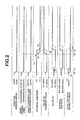
- a response delay occurs from a time at which the opening angle of EGR control valve 21 is modified to a time at which the variation in the external EGR rate within the cylinder actually appears. Therefore, as shown in a broken line in Fig. 2 , when a target value (a command value) of variably operated valve mechanism 28 is modified so that the valve overlap between the intake valve and the exhaust valve is expanded (namely set to a target valve overlap quantity in the low load state) at a timing T01 at which EGR control valve 21 is closed, the internal EGR rate within the cylinder is varied (increased) before the external EGR rate is varied (decreased). Thus, the total EGR rate within the cylinder transiently largely exceeds the target EGR rate.
- the target value (or the command value) of variably operated valve mechanism 28 is modified to a low load transient time provisional value at which the valve overlap quantity between the intake valve and the exhaust valve is smaller than the present valve overlap quantity, at timing T01 at which the opening angle of EGR control valve 21 is modified, and is modified from the low load transient time provisional value to the target value at the time of the low load state, at a timing T31 at which the variation of the external EGR rate within the cylinder appears from the time at which the opening angle of EGR control valve 21 is modified.
- variably operated valve mechanism 28 provides a response delay from a time at which the target value is modified to a time at which the valve open timing of the intake valve is actually started to be varied (a timing of T11 at which the valve open timing of the intake valve is started to be varied).
- a timing of T11 at which the valve open timing of the intake valve is started to be varied a timing of T11 at which the valve open timing of the intake valve is started to be varied.
- the low load transient time provisional value is set so that the total EGR rate within the cylinder is not larger than the target EGR rate in a case where EGR control valve 21 is closed and provides a value smaller than the valve overlap quantity when EGR control valve 21 is closed. It should be noted that the low load transient time provisional value is set so that the total EGR rate within the cylinder is not larger than the target EGR rate in a case where EGR control valve 21 is closed and is smaller than the valve overlap quantity when EGR control valve 21 is closed.
- the EGR rate at a predetermined position of the intake system at which the EGR rate is varied is reflected on the control of variable valve operated mechanism 28 at a timing T21 which is preceded by a response time ⁇ t (a time duration from a time at which the target value of variably operated valve mechanism 28 is modified to a time at which the open timing of the intake valve is actually varied so that the valve overlap quantity between the intake valve and the exhaust valve is started to be varied) of variably operated mechanism 28 from timing T31 at which the external EGR rate within the cylinder is varied due to the modification of the opening angle of EGR control valve.
- a response time ⁇ t a time duration from a time at which the target value of variably operated valve mechanism 28 is modified to a time at which the open timing of the intake valve is actually varied so that the valve overlap quantity between the intake valve and the exhaust valve is started to be varied
- the target value of the valve overlap quantity between the intake valve and the exhaust valve is modified from the above-described low load transient time provisional value to the target value at the time of the low load.
- the variation (increase) of the internal EGR within the cylinder can follow the variation (decrease) of the external EGR rate within the cylinder. It can be suppressed that the total EGR rate within the cylinder is transiently largely below the target EGR rate. Consequently, a worsening of the driveability can be avoided.
- the EGR rate at the above-described predetermined position is estimated, for example, on a basis of the intake air quantity, the EGR rate at a junction section 31 between EGR passage 20 and intake passage 2, and a volume of a flow passage from EGR control valve 21 to the above-described predetermined position. It should be noted that the EGR rate at the above-described position may directly be detected by means of a sensor.
- a characteristic line Ef in Fig. 2 indicates a variation of an estimated EGR rate at the above-described predetermined position.
- a characteristic line Et in Fig. 2 indicates the target value of the total EGR rate within the cylinder.
- a delay time Td is predicted from a time at which the opening angle of EGR control valve 21 is modified to a time at which the EGR rate at the above-described predetermined position is started to be varied.
- the target value of the valve overlap quantity between the intake valve and the exhaust valve is modified from the above-described low load transient time provisional value to the target value at the time of the low load state.
- the variation (increase) of internal EGR rate within the cylinder can follow the variation (decrease) of the external EGR rate within the cylinder.
- This delay time Td can be estimated on a basis of, for example, the intake air quantity and a volume of a flow passage from EGR control valve 21 to the above-described predetermined position.
- EGR control valve 21 adjusting the external EGR is opened and the valve overlap quantity between the intake valve and the exhaust valve adjusting the internal EGR is controlled to be relatively small.
- a response delay occurs from a time at which the opening angle of EGR control valve 21 is modified to a time at which the variation in the external EGR rate within the cylinder actually appears. Therefore, as shown by a broken line in Fig. 3 , at a timing T02 at which EGR control valve 21 is valve opened, the target value (command value) of variably operated valve mechanism 28 is modified in such a way that the valve overlap between the intake valve and the exhaust valve is contracted (is set to be the target valve overlap quantity at the time of the high load).
- a characteristic line Ef in Fig. 3 indicates the variation of the estimated EGR rate at the above-described predetermined position.
- a characteristic line Et in Fig. 3 indicates the target value of the total EGR rate within the cylinder.
- the target value (the command value) of variably operated valve mechanism 28 is modified to a high load transient time provisional value at which the valve overlap quantity between the intake valve and the exhaust valve is larger than the present valve overlap quantity and is further modified from the high load transient time provisional value to the target value at the time of high load at a timing T32 at which the variation in the external EGR rate within the cylinder appears from the time at which the opening angle of EGR control valve 21 is modified.
- the high load transient time provisional value is set so that the total EGR rate within the cylinder is not smaller than the target EGR rate in a case where the EGR control valve 21 is opened and is a value larger than the valve overlap quantity when EGR control valve 21 is valve opened.
- the opening angle of throttle valve 5 is increased and, at timing T02 at which EGR control valve 21 is valve opened, the valve overlap quantity between the intake valve and the exhaust valve is not modified to the target value at the high load state but is controlled in a direction in which the valve overlap between the intake valve and the exhaust valve is once expanded as the above-described high load transient time provisional value.
- the total EGR rate within the cylinder is transiently largely below the target EGR rate after the modification of the opening angle of EGR control valve 21.
- the EGR rate at the above-described predetermined position in which the EGR rate is varied at a timing T22 preceded from timing T32 at which the external EGR rate within the cylinder is varied due to the modification of the opening angle of EGR valve 21 by response time ⁇ t of variably operated valve mechanism 28 is reflected on the control of variably operated valve mechanism 28.
- the target value of the valve overlap quantity between the intake valve and the exhaust valve is modified from the above-described high load transient time provisional value to the target value at the time of the high load at timing T22 at which the external EGR rate at the above-described predetermined position is varied in response to the valve open of EGR control value.
- the variation (decrease) of the internal EGR rate within the cylinder can follow the variation (increase) of the external EGR rate within the cylinder.
- it can be suppressed that the total EGR rate within the cylinder transiently largely exceeds the target EGR rate. The worsening of driveability can, consequently, be avoided.
- delay time Td from the time at which the opening angle of EGR control valve 21 is modified to a time at which the EGR rate is started to be varied at the above-described predetermined position is predicted and, after a passage of this delay time Td, the target value of the valve overlap quantity between the intake valve and the exhaust valve is modified from the above-described high load transient time provisional value to the target value at the time of the high load.
- the variation in the internal EGR rate within the cylinder can follow the variation of the external EGR rate within the cylinder.
- the above-described predetermined position may be modified in accordance with this response time ⁇ t.
- a response speed of variably operated valve mechanism 28 is relatively delayed as an oil temperature or a cooling water temperature becomes lower.
- the above-described predetermined position may relatively be modified to be upstream side within the intake system.
- an adjustment of an internal EGR gas quantity by means of variably operated valve mechanism 28 is carried out within an operation enable (operable) range of variably operated valve mechanism 28.
- the adjustment of the internal EGR gas quantity is carried out with an operation limit of the above-described operation enable range as a limit. That is to say, in a case where the calculated target value of the variably operated valve mechanism 28 advances the open timing of the intake valve to a further advance angle than a most advance angle position, control unit 25 controls variably operated valve mechanism 28 in order for the open timing of the intake valve to the most advance angle position.
- control unit 25 controls variably operated valve mechanism 28 in order for the open timing of the intake valve to be the most retardation angle position.
- Fig. 4 is a block diagram representing a control content for variably operated valve mechanism 28 in this embodiment.
- control unit 25 calculates a basic target value (the valve timing) of variably operated valve mechanism 28 in a steady state from an engine revolution number and the intake air quantity.
- control unit 25 calculates the EGR rate at the above-described predetermined position of the intake system using the target EGR rate determined according to the driving condition, the intake air quantity, and the volume of the flow passage from the EGR control valve 21 to the predetermined position within the intake system.
- control unit 25 calculates a difference (a separation quantity) between the EGR rate calculated at S2 and the target EGR rate determined according to the driving condition.
- control unit 25 calculates a valve timing correction quantity with respect to the target value in the steady state of variably operated valve mechanism 28 so that the EGR rate at the above-described predetermined position within the intake system becomes equal to the EGR rate calculated at S2 using the separation quantity calculated at S3 and the engine revolution number.
- control unit 25 corrects the basic target value calculated at S1 by the valve timing correction quantity calculated at S4 and sets the corrected value as the target value of variably operated valve mechanism 28.
- the operated valve mechanism for the intake valve side is the variably operated valve mechanism.
- the present invention is applicable to the variably operated valve mechanism which can modify the open timing of the exhaust valve by advancing or retarding a phase of a lift center angle of the exhaust valve (a phase with respect to a crankshaft (not shown)).
- the open timing of the intake valve is advanced by means of the variably operated valve mechanism for the intake valve side and the opening timing of the intake valve is advanced by means of the variably operated valve mechanism for the intake valve side and the closure timing of the exhaust valve is retarded by means of the variably operated valve mechanism for the exhaust valve side so that the valve overlap between the intake valve and exhaust valve may be increased.
- the variably operated valve mechanism for the intake valve side and the variably operated valve mechanism for the exhaust valve side may be the variably operated valve mechanism which can simultaneously and continuously expand or contract both of a lift quantity and a working angle of the intake valve or the exhaust valve.
- valve timing control device in a case of the non-turbo charge time has been described.
- variably operated valve mechanism 28 is controlled which is the valve timing control device in the same way as the non-turbo charge time.
Landscapes
- Engineering & Computer Science (AREA)
- Mechanical Engineering (AREA)
- General Engineering & Computer Science (AREA)
- Chemical & Material Sciences (AREA)
- Combustion & Propulsion (AREA)
- Output Control And Ontrol Of Special Type Engine (AREA)
- Exhaust-Gas Circulating Devices (AREA)
- Valve Device For Special Equipments (AREA)
Applications Claiming Priority (2)
| Application Number | Priority Date | Filing Date | Title |
|---|---|---|---|
| JP2012164252 | 2012-07-25 | ||
| PCT/JP2013/065992 WO2014017189A1 (fr) | 2012-07-25 | 2013-06-10 | Dispositif de commande et procédé de commande de moteur à combustion interne |
Publications (3)
| Publication Number | Publication Date |
|---|---|
| EP2878792A1 true EP2878792A1 (fr) | 2015-06-03 |
| EP2878792A4 EP2878792A4 (fr) | 2016-03-30 |
| EP2878792B1 EP2878792B1 (fr) | 2017-04-19 |
Family
ID=49997006
Family Applications (1)
| Application Number | Title | Priority Date | Filing Date |
|---|---|---|---|
| EP13822609.7A Not-in-force EP2878792B1 (fr) | 2012-07-25 | 2013-06-10 | Dispositif de commande et procédé de commande de moteur à combustion interne |
Country Status (5)
| Country | Link |
|---|---|
| US (1) | US9964055B2 (fr) |
| EP (1) | EP2878792B1 (fr) |
| JP (1) | JP5733478B2 (fr) |
| CN (1) | CN104471216B (fr) |
| WO (1) | WO2014017189A1 (fr) |
Cited By (3)
| Publication number | Priority date | Publication date | Assignee | Title |
|---|---|---|---|---|
| FR3041999A1 (fr) * | 2015-10-02 | 2017-04-07 | Peugeot Citroen Automobiles Sa | Procede de limitation du taux de gaz recircules pour un moteur a dephaseurs lors d’une phase transitoire de charge en air |
| WO2020084204A1 (fr) * | 2018-10-24 | 2020-04-30 | Psa Automobiles Sa | Procede de regulation du debit d'air d'une vanne de recirculation des gaz a l'echappement utilisant un modele de rendement volumetrique anticipe |
| EP4006326A4 (fr) * | 2019-07-26 | 2022-07-27 | Nissan Motor Company Limited | Procédé et dispositif de commande de moteur à combustion interne |
Families Citing this family (9)
| Publication number | Priority date | Publication date | Assignee | Title |
|---|---|---|---|---|
| KR101601088B1 (ko) * | 2013-12-23 | 2016-03-09 | 현대자동차주식회사 | 엔진 냉각 시스템 |
| DE102015218044A1 (de) * | 2015-09-21 | 2017-03-23 | Robert Bosch Gmbh | Verfahren zum Regeln einer internen Abgasrückführrate bei einer Brennkraftmaschine |
| US10330034B2 (en) * | 2016-04-29 | 2019-06-25 | Ford Global Technologies, Llc | Device and method for predicting the exhaust gas recirculation rate |
| KR101956030B1 (ko) | 2016-11-11 | 2019-03-08 | 현대자동차 주식회사 | 엔진 시스템 제어 방법 및 장치 |
| JP6528788B2 (ja) * | 2017-01-17 | 2019-06-12 | トヨタ自動車株式会社 | 内燃機関の制御装置 |
| JP6930178B2 (ja) * | 2017-03-30 | 2021-09-01 | 三菱自動車工業株式会社 | 内燃機関の制御装置 |
| JP6834752B2 (ja) * | 2017-04-28 | 2021-02-24 | トヨタ自動車株式会社 | 過給機付き内燃機関の制御装置 |
| KR102261363B1 (ko) * | 2017-05-12 | 2021-06-07 | 현대자동차주식회사 | 저압 egr 시스템의 제어 장치 및 제어 방법 |
| JP2019163735A (ja) * | 2018-03-20 | 2019-09-26 | 日立オートモティブシステムズ株式会社 | 内燃機関制御装置 |
Family Cites Families (19)
| Publication number | Priority date | Publication date | Assignee | Title |
|---|---|---|---|---|
| JP3223731B2 (ja) * | 1994-12-06 | 2001-10-29 | 日産自動車株式会社 | 内燃機関のegr制御装置 |
| JP4265382B2 (ja) * | 2003-11-13 | 2009-05-20 | トヨタ自動車株式会社 | 予混合圧縮着火内燃機関 |
| US7367188B2 (en) * | 2006-07-28 | 2008-05-06 | Ford Global Technologies, Llc | System and method for diagnostic of low pressure exhaust gas recirculation system and adapting of measurement devices |
| JP2007113485A (ja) * | 2005-10-20 | 2007-05-10 | Hitachi Ltd | 内燃機関の制御方法及び制御装置 |
| JP4618141B2 (ja) * | 2006-01-20 | 2011-01-26 | トヨタ自動車株式会社 | 内燃機関の排気ガス還流装置 |
| JP2007315230A (ja) | 2006-05-24 | 2007-12-06 | Toyota Motor Corp | 内燃機関の排気還流装置 |
| JP4872644B2 (ja) | 2006-12-14 | 2012-02-08 | トヨタ自動車株式会社 | Egr装置付き内燃機関 |
| JP4867713B2 (ja) * | 2007-02-27 | 2012-02-01 | トヨタ自動車株式会社 | Egr装置付内燃機関の制御装置 |
| JP2008309030A (ja) * | 2007-06-13 | 2008-12-25 | Toyota Motor Corp | 内燃機関の排気還流装置 |
| JP4442659B2 (ja) * | 2007-08-09 | 2010-03-31 | トヨタ自動車株式会社 | 内燃機関の排気浄化装置 |
| JP2009138650A (ja) * | 2007-12-07 | 2009-06-25 | Denso Corp | 内燃機関の可変バルブタイミング制御装置 |
| JP2009167868A (ja) * | 2008-01-15 | 2009-07-30 | Toyota Motor Corp | 予混合圧縮自着火内燃機関 |
| JP4941413B2 (ja) * | 2008-06-19 | 2012-05-30 | トヨタ自動車株式会社 | 内燃機関の制御装置 |
| US20100077990A1 (en) * | 2008-09-26 | 2010-04-01 | Mazda Motor Corporation | Control of spark ignited internal combustion engine |
| JP5107963B2 (ja) | 2009-05-26 | 2012-12-26 | 日立オートモティブシステムズ株式会社 | エンジンの制御装置 |
| US8103427B2 (en) * | 2009-09-25 | 2012-01-24 | Cummins Inc. | EGR flow compensation for a diesel air handling system |
| US8103428B2 (en) * | 2011-01-11 | 2012-01-24 | Ford Global Technologies, Llc | Method for controlling an engine |
| JP6041049B2 (ja) * | 2013-05-14 | 2016-12-07 | トヨタ自動車株式会社 | 内燃機関の制御装置 |
| US9587617B2 (en) * | 2014-12-10 | 2017-03-07 | Cummins Inc. | Method of spark timing adjustment for an internal combustion engine |
-
2013
- 2013-06-10 CN CN201380038006.1A patent/CN104471216B/zh not_active Expired - Fee Related
- 2013-06-10 EP EP13822609.7A patent/EP2878792B1/fr not_active Not-in-force
- 2013-06-10 WO PCT/JP2013/065992 patent/WO2014017189A1/fr not_active Ceased
- 2013-06-10 US US14/414,980 patent/US9964055B2/en active Active
- 2013-06-10 JP JP2014526809A patent/JP5733478B2/ja not_active Expired - Fee Related
Cited By (5)
| Publication number | Priority date | Publication date | Assignee | Title |
|---|---|---|---|---|
| FR3041999A1 (fr) * | 2015-10-02 | 2017-04-07 | Peugeot Citroen Automobiles Sa | Procede de limitation du taux de gaz recircules pour un moteur a dephaseurs lors d’une phase transitoire de charge en air |
| WO2020084204A1 (fr) * | 2018-10-24 | 2020-04-30 | Psa Automobiles Sa | Procede de regulation du debit d'air d'une vanne de recirculation des gaz a l'echappement utilisant un modele de rendement volumetrique anticipe |
| FR3087842A1 (fr) * | 2018-10-24 | 2020-05-01 | Psa Automobiles Sa | Procede de regulation du debit d’air d’une vanne de recirculation des gaz a l’echappement utilisant un modele de rendement volumetrique anticipe |
| EP4006326A4 (fr) * | 2019-07-26 | 2022-07-27 | Nissan Motor Company Limited | Procédé et dispositif de commande de moteur à combustion interne |
| US11754004B2 (en) | 2019-07-26 | 2023-09-12 | Nissan Motor Co., Ltd. | Control method and control device for internal combustion engine |
Also Published As
| Publication number | Publication date |
|---|---|
| JP5733478B2 (ja) | 2015-06-10 |
| US20150192079A1 (en) | 2015-07-09 |
| JPWO2014017189A1 (ja) | 2016-07-07 |
| EP2878792B1 (fr) | 2017-04-19 |
| US9964055B2 (en) | 2018-05-08 |
| CN104471216B (zh) | 2016-04-27 |
| CN104471216A (zh) | 2015-03-25 |
| EP2878792A4 (fr) | 2016-03-30 |
| WO2014017189A1 (fr) | 2014-01-30 |
Similar Documents
| Publication | Publication Date | Title |
|---|---|---|
| EP2878792B1 (fr) | Dispositif de commande et procédé de commande de moteur à combustion interne | |
| EP2803842B1 (fr) | Dispositif de commande pour moteur à combustion interne | |
| EP2963263B1 (fr) | Dispositif de commande pour moteur à combustion interne | |
| US9624824B2 (en) | Control device and control method for internal combustion engine | |
| JP2009002283A (ja) | 内燃機関の制御装置 | |
| US9200562B2 (en) | Control device for internal combustion engine with turbo supercharger | |
| US9228538B2 (en) | Internal combustion engine control apparatus | |
| JP4893514B2 (ja) | 過給機付き内燃機関の制御装置 | |
| EP3730770B1 (fr) | Moteur à combustion interne et son procédé de commande | |
| US9303553B2 (en) | Turbo speed control for mode transitions in a dual turbo system | |
| JP6486852B2 (ja) | 内燃機関の制御装置及び制御方法 | |
| US9303569B2 (en) | Control device for internal combustion engine | |
| JP5263249B2 (ja) | 過給機付き内燃機関の可変バルブタイミング制御装置 | |
| EP2636874B1 (fr) | Dispositif de commande pour moteur thermique | |
| JP2019039405A (ja) | エンジンの制御装置 | |
| JP5338709B2 (ja) | 内燃機関の制御装置 | |
| JP2017180195A (ja) | エンジンの制御装置 | |
| JP2010261358A (ja) | 内燃機関の制御装置 | |
| JP2017053244A (ja) | エンジンの制御装置 | |
| JP2013147956A (ja) | エンジンの動弁装置 |
Legal Events
| Date | Code | Title | Description |
|---|---|---|---|
| PUAI | Public reference made under article 153(3) epc to a published international application that has entered the european phase |
Free format text: ORIGINAL CODE: 0009012 |
|
| 17P | Request for examination filed |
Effective date: 20150120 |
|
| AK | Designated contracting states |
Kind code of ref document: A1 Designated state(s): AL AT BE BG CH CY CZ DE DK EE ES FI FR GB GR HR HU IE IS IT LI LT LU LV MC MK MT NL NO PL PT RO RS SE SI SK SM TR |
|
| AX | Request for extension of the european patent |
Extension state: BA ME |
|
| DAX | Request for extension of the european patent (deleted) | ||
| RA4 | Supplementary search report drawn up and despatched (corrected) |
Effective date: 20160226 |
|
| RIC1 | Information provided on ipc code assigned before grant |
Ipc: F02M 26/00 20160101ALI20160315BHEP Ipc: F02D 13/02 20060101AFI20160315BHEP Ipc: F02D 21/08 20060101ALI20160315BHEP Ipc: F02B 37/00 20060101ALI20160315BHEP Ipc: F02D 23/00 20060101ALI20160315BHEP |
|
| GRAP | Despatch of communication of intention to grant a patent |
Free format text: ORIGINAL CODE: EPIDOSNIGR1 |
|
| RIC1 | Information provided on ipc code assigned before grant |
Ipc: F02D 21/08 20060101ALI20161028BHEP Ipc: F02B 37/00 20060101ALI20161028BHEP Ipc: F02D 23/00 20060101ALI20161028BHEP Ipc: F02D 41/00 20060101ALI20161028BHEP Ipc: F02D 13/02 20060101AFI20161028BHEP |
|
| INTG | Intention to grant announced |
Effective date: 20161208 |
|
| GRAS | Grant fee paid |
Free format text: ORIGINAL CODE: EPIDOSNIGR3 |
|
| GRAA | (expected) grant |
Free format text: ORIGINAL CODE: 0009210 |
|
| AK | Designated contracting states |
Kind code of ref document: B1 Designated state(s): AL AT BE BG CH CY CZ DE DK EE ES FI FR GB GR HR HU IE IS IT LI LT LU LV MC MK MT NL NO PL PT RO RS SE SI SK SM TR |
|
| REG | Reference to a national code |
Ref country code: GB Ref legal event code: FG4D |
|
| REG | Reference to a national code |
Ref country code: CH Ref legal event code: EP |
|
| REG | Reference to a national code |
Ref country code: FR Ref legal event code: PLFP Year of fee payment: 5 |
|
| REG | Reference to a national code |
Ref country code: AT Ref legal event code: REF Ref document number: 886216 Country of ref document: AT Kind code of ref document: T Effective date: 20170515 |
|
| REG | Reference to a national code |
Ref country code: IE Ref legal event code: FG4D |
|
| REG | Reference to a national code |
Ref country code: DE Ref legal event code: R096 Ref document number: 602013020137 Country of ref document: DE |
|
| REG | Reference to a national code |
Ref country code: NL Ref legal event code: MP Effective date: 20170419 |
|
| REG | Reference to a national code |
Ref country code: LT Ref legal event code: MG4D |
|
| REG | Reference to a national code |
Ref country code: AT Ref legal event code: MK05 Ref document number: 886216 Country of ref document: AT Kind code of ref document: T Effective date: 20170419 |
|
| PG25 | Lapsed in a contracting state [announced via postgrant information from national office to epo] |
Ref country code: NL Free format text: LAPSE BECAUSE OF FAILURE TO SUBMIT A TRANSLATION OF THE DESCRIPTION OR TO PAY THE FEE WITHIN THE PRESCRIBED TIME-LIMIT Effective date: 20170419 |
|
| PG25 | Lapsed in a contracting state [announced via postgrant information from national office to epo] |
Ref country code: FI Free format text: LAPSE BECAUSE OF FAILURE TO SUBMIT A TRANSLATION OF THE DESCRIPTION OR TO PAY THE FEE WITHIN THE PRESCRIBED TIME-LIMIT Effective date: 20170419 Ref country code: GR Free format text: LAPSE BECAUSE OF FAILURE TO SUBMIT A TRANSLATION OF THE DESCRIPTION OR TO PAY THE FEE WITHIN THE PRESCRIBED TIME-LIMIT Effective date: 20170720 Ref country code: LT Free format text: LAPSE BECAUSE OF FAILURE TO SUBMIT A TRANSLATION OF THE DESCRIPTION OR TO PAY THE FEE WITHIN THE PRESCRIBED TIME-LIMIT Effective date: 20170419 Ref country code: AT Free format text: LAPSE BECAUSE OF FAILURE TO SUBMIT A TRANSLATION OF THE DESCRIPTION OR TO PAY THE FEE WITHIN THE PRESCRIBED TIME-LIMIT Effective date: 20170419 Ref country code: HR Free format text: LAPSE BECAUSE OF FAILURE TO SUBMIT A TRANSLATION OF THE DESCRIPTION OR TO PAY THE FEE WITHIN THE PRESCRIBED TIME-LIMIT Effective date: 20170419 Ref country code: ES Free format text: LAPSE BECAUSE OF FAILURE TO SUBMIT A TRANSLATION OF THE DESCRIPTION OR TO PAY THE FEE WITHIN THE PRESCRIBED TIME-LIMIT Effective date: 20170419 Ref country code: NO Free format text: LAPSE BECAUSE OF FAILURE TO SUBMIT A TRANSLATION OF THE DESCRIPTION OR TO PAY THE FEE WITHIN THE PRESCRIBED TIME-LIMIT Effective date: 20170719 |
|
| PG25 | Lapsed in a contracting state [announced via postgrant information from national office to epo] |
Ref country code: IS Free format text: LAPSE BECAUSE OF FAILURE TO SUBMIT A TRANSLATION OF THE DESCRIPTION OR TO PAY THE FEE WITHIN THE PRESCRIBED TIME-LIMIT Effective date: 20170819 Ref country code: RS Free format text: LAPSE BECAUSE OF FAILURE TO SUBMIT A TRANSLATION OF THE DESCRIPTION OR TO PAY THE FEE WITHIN THE PRESCRIBED TIME-LIMIT Effective date: 20170419 Ref country code: PL Free format text: LAPSE BECAUSE OF FAILURE TO SUBMIT A TRANSLATION OF THE DESCRIPTION OR TO PAY THE FEE WITHIN THE PRESCRIBED TIME-LIMIT Effective date: 20170419 Ref country code: LV Free format text: LAPSE BECAUSE OF FAILURE TO SUBMIT A TRANSLATION OF THE DESCRIPTION OR TO PAY THE FEE WITHIN THE PRESCRIBED TIME-LIMIT Effective date: 20170419 Ref country code: BG Free format text: LAPSE BECAUSE OF FAILURE TO SUBMIT A TRANSLATION OF THE DESCRIPTION OR TO PAY THE FEE WITHIN THE PRESCRIBED TIME-LIMIT Effective date: 20170719 Ref country code: SE Free format text: LAPSE BECAUSE OF FAILURE TO SUBMIT A TRANSLATION OF THE DESCRIPTION OR TO PAY THE FEE WITHIN THE PRESCRIBED TIME-LIMIT Effective date: 20170419 |
|
| REG | Reference to a national code |
Ref country code: DE Ref legal event code: R097 Ref document number: 602013020137 Country of ref document: DE |
|
| PG25 | Lapsed in a contracting state [announced via postgrant information from national office to epo] |
Ref country code: CZ Free format text: LAPSE BECAUSE OF FAILURE TO SUBMIT A TRANSLATION OF THE DESCRIPTION OR TO PAY THE FEE WITHIN THE PRESCRIBED TIME-LIMIT Effective date: 20170419 Ref country code: SK Free format text: LAPSE BECAUSE OF FAILURE TO SUBMIT A TRANSLATION OF THE DESCRIPTION OR TO PAY THE FEE WITHIN THE PRESCRIBED TIME-LIMIT Effective date: 20170419 Ref country code: MC Free format text: LAPSE BECAUSE OF FAILURE TO SUBMIT A TRANSLATION OF THE DESCRIPTION OR TO PAY THE FEE WITHIN THE PRESCRIBED TIME-LIMIT Effective date: 20170419 Ref country code: RO Free format text: LAPSE BECAUSE OF FAILURE TO SUBMIT A TRANSLATION OF THE DESCRIPTION OR TO PAY THE FEE WITHIN THE PRESCRIBED TIME-LIMIT Effective date: 20170419 Ref country code: DK Free format text: LAPSE BECAUSE OF FAILURE TO SUBMIT A TRANSLATION OF THE DESCRIPTION OR TO PAY THE FEE WITHIN THE PRESCRIBED TIME-LIMIT Effective date: 20170419 Ref country code: EE Free format text: LAPSE BECAUSE OF FAILURE TO SUBMIT A TRANSLATION OF THE DESCRIPTION OR TO PAY THE FEE WITHIN THE PRESCRIBED TIME-LIMIT Effective date: 20170419 |
|
| REG | Reference to a national code |
Ref country code: CH Ref legal event code: PL |
|
| PLBE | No opposition filed within time limit |
Free format text: ORIGINAL CODE: 0009261 |
|
| STAA | Information on the status of an ep patent application or granted ep patent |
Free format text: STATUS: NO OPPOSITION FILED WITHIN TIME LIMIT |
|
| PG25 | Lapsed in a contracting state [announced via postgrant information from national office to epo] |
Ref country code: IT Free format text: LAPSE BECAUSE OF FAILURE TO SUBMIT A TRANSLATION OF THE DESCRIPTION OR TO PAY THE FEE WITHIN THE PRESCRIBED TIME-LIMIT Effective date: 20170419 Ref country code: SM Free format text: LAPSE BECAUSE OF FAILURE TO SUBMIT A TRANSLATION OF THE DESCRIPTION OR TO PAY THE FEE WITHIN THE PRESCRIBED TIME-LIMIT Effective date: 20170419 |
|
| REG | Reference to a national code |
Ref country code: IE Ref legal event code: MM4A |
|
| 26N | No opposition filed |
Effective date: 20180122 |
|
| PG25 | Lapsed in a contracting state [announced via postgrant information from national office to epo] |
Ref country code: CH Free format text: LAPSE BECAUSE OF NON-PAYMENT OF DUE FEES Effective date: 20170630 Ref country code: LI Free format text: LAPSE BECAUSE OF NON-PAYMENT OF DUE FEES Effective date: 20170630 Ref country code: IE Free format text: LAPSE BECAUSE OF NON-PAYMENT OF DUE FEES Effective date: 20170610 Ref country code: LU Free format text: LAPSE BECAUSE OF NON-PAYMENT OF DUE FEES Effective date: 20170610 |
|
| REG | Reference to a national code |
Ref country code: FR Ref legal event code: PLFP Year of fee payment: 6 |
|
| PG25 | Lapsed in a contracting state [announced via postgrant information from national office to epo] |
Ref country code: SI Free format text: LAPSE BECAUSE OF FAILURE TO SUBMIT A TRANSLATION OF THE DESCRIPTION OR TO PAY THE FEE WITHIN THE PRESCRIBED TIME-LIMIT Effective date: 20170419 |
|
| REG | Reference to a national code |
Ref country code: BE Ref legal event code: MM Effective date: 20170630 |
|
| PG25 | Lapsed in a contracting state [announced via postgrant information from national office to epo] |
Ref country code: BE Free format text: LAPSE BECAUSE OF NON-PAYMENT OF DUE FEES Effective date: 20170630 |
|
| PG25 | Lapsed in a contracting state [announced via postgrant information from national office to epo] |
Ref country code: MT Free format text: LAPSE BECAUSE OF NON-PAYMENT OF DUE FEES Effective date: 20170610 |
|
| PG25 | Lapsed in a contracting state [announced via postgrant information from national office to epo] |
Ref country code: HU Free format text: LAPSE BECAUSE OF FAILURE TO SUBMIT A TRANSLATION OF THE DESCRIPTION OR TO PAY THE FEE WITHIN THE PRESCRIBED TIME-LIMIT; INVALID AB INITIO Effective date: 20130610 |
|
| PG25 | Lapsed in a contracting state [announced via postgrant information from national office to epo] |
Ref country code: CY Free format text: LAPSE BECAUSE OF FAILURE TO SUBMIT A TRANSLATION OF THE DESCRIPTION OR TO PAY THE FEE WITHIN THE PRESCRIBED TIME-LIMIT Effective date: 20170419 |
|
| PG25 | Lapsed in a contracting state [announced via postgrant information from national office to epo] |
Ref country code: MK Free format text: LAPSE BECAUSE OF FAILURE TO SUBMIT A TRANSLATION OF THE DESCRIPTION OR TO PAY THE FEE WITHIN THE PRESCRIBED TIME-LIMIT Effective date: 20170419 |
|
| PG25 | Lapsed in a contracting state [announced via postgrant information from national office to epo] |
Ref country code: TR Free format text: LAPSE BECAUSE OF FAILURE TO SUBMIT A TRANSLATION OF THE DESCRIPTION OR TO PAY THE FEE WITHIN THE PRESCRIBED TIME-LIMIT Effective date: 20170419 |
|
| PG25 | Lapsed in a contracting state [announced via postgrant information from national office to epo] |
Ref country code: PT Free format text: LAPSE BECAUSE OF FAILURE TO SUBMIT A TRANSLATION OF THE DESCRIPTION OR TO PAY THE FEE WITHIN THE PRESCRIBED TIME-LIMIT Effective date: 20170419 |
|
| PG25 | Lapsed in a contracting state [announced via postgrant information from national office to epo] |
Ref country code: AL Free format text: LAPSE BECAUSE OF FAILURE TO SUBMIT A TRANSLATION OF THE DESCRIPTION OR TO PAY THE FEE WITHIN THE PRESCRIBED TIME-LIMIT Effective date: 20170419 |
|
| PGFP | Annual fee paid to national office [announced via postgrant information from national office to epo] |
Ref country code: GB Payment date: 20220425 Year of fee payment: 10 Ref country code: FR Payment date: 20220408 Year of fee payment: 10 Ref country code: DE Payment date: 20220420 Year of fee payment: 10 |
|
| REG | Reference to a national code |
Ref country code: DE Ref legal event code: R119 Ref document number: 602013020137 Country of ref document: DE |
|
| GBPC | Gb: european patent ceased through non-payment of renewal fee |
Effective date: 20230610 |
|
| PG25 | Lapsed in a contracting state [announced via postgrant information from national office to epo] |
Ref country code: DE Free format text: LAPSE BECAUSE OF NON-PAYMENT OF DUE FEES Effective date: 20240103 Ref country code: GB Free format text: LAPSE BECAUSE OF NON-PAYMENT OF DUE FEES Effective date: 20230610 |
|
| PG25 | Lapsed in a contracting state [announced via postgrant information from national office to epo] |
Ref country code: FR Free format text: LAPSE BECAUSE OF NON-PAYMENT OF DUE FEES Effective date: 20230630 |